Embed Size (px)
Citation preview
OverviewXW
Series E-StopsInterlock Sw
itchesEnabling Sw
itchesSafety Control
Light CurtainsAS-Interface Safety at W
orkSafety
Table of Contents LED Machine Lighting - Pg. 1 Automation & Sensing - Pg. 27 Safety - Pg. 255 Switching & Controls - Pg. 449 Index - Pg. 933
www.IDEC.com/safety
Safety
Control
Selection Guide .......................................... 394
Safety Relay HR1S-AC .............................. 395
Safety Relay HR1S-AF................................ 398
Safety Relay HR1S-DM .............................. 401
Safety Relay HR1S-ATE .............................. 403
Safety Relay HR2S-301 .............................. 406
Safety Relay HR2S-332N ........................... 411
FS1A Multi-function Safety Relay ............. 416
This document provided by Barr-Thorp Electric Co., Inc. 800-473-9123 www.barr-thorp.com
Over
view
XW S
erie
s E-
Stop
sIn
terlo
ck S
witc
hes
Enab
ling
Switc
hes
Safe
ty C
ontr
olLi
ght C
urta
ins
AS-In
terfa
ce S
afet
y at
Wor
kSelection Guide Safety Control
394 www.IDEC.com
Selection Guide
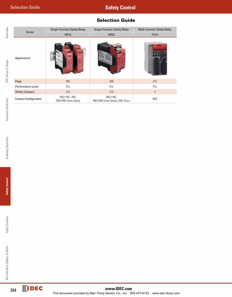
SeriesSingle Function Safety Relay Single Function Safety Relay Multi-function Safety Relay
HR1S HR2S FS1A
Appearance
Page 395 406 416
Performance Level PLe PLe PLe
Safety Category 3/4 3/4 4
Contact Configuration 1NO/1NC, 2NC, 2NO/3NO (time delay)
3NO/1NC, 3NO/3NO (time delay) /2NC (Aux.) 4NO
This document provided by Barr-Thorp Electric Co., Inc. 800-473-9123 www.barr-thorp.com
395800-262-IDEC (4332) • USA & Canada
HR1S-ACSafety ControlOverview
XW Series E-Stops
Interlock Switches
Enabling Switches
Safety ControlLight Curtains
AS-Interface Safety at Work
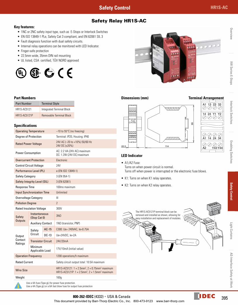
Safety Relay HR1S-AC Key features:
• 1NC or 2NC safety input type, such as E-Stops or Interlock Switches• EN ISO 13849-1 PLe, Safety Cat 3 compliant, and EN 62061 SIL 3• Fault diagnosis function with dual safety circuits.• Internal relay operations can be moni tored with LED Indicator.• Finger-safe protection• 22.5mm wide, 35mm DIN rail mounting• UL listed, CSA certified, TÜV NORD approved
Part NumbersPart Number Terminal Style
HR1S-AC5121 Integrated Terminal Block
HR1S-AC5121P Removable Terminal Block
SpecificationsOperating Temperature –10 to 55°C (no freezing)
Degree of Protection Terminal: IP20, Housing: IP40
Rated Power Voltage 24V AC (–20 to +10%) 50/60 Hz24V DC (±20%)
Power Consumption AC: 2.2 VA (24V AC) maximum DC: 1.2W (24V DC) maximum
Overcurrent Protection Electronic
Control Circuit Voltage 24V
Performance Level (PL) e (EN ISO 13849-1)
Safety Category 3 (EN 954-1)
Safety Integrity Level (SIL) 3 (EN 62061)
Response Time 100ms maximum
Input Synchronization Time Unlimited
Overvoltage Category III
Pollution Degree 2
Rated Insulation Voltage 300V
Safety Outputs
Instantaneous (Stop Cat 0) 3NO
Auxiliary Contact 1NO (transistor, PNP)
Output Contact Ratings
Safety Circuit
AC-15 C300: Ue= 240VAC, Ie=0.75A
DC-13 Ue=24VDC, Ie=2A
Transistor Circuit 24V/20mA
Minimum Applicable Load 17V/10mA (initial value)
Operation Frequency 1200 operations/h maximum
Rated Current Safety circuit output total: 10.5A maximum
Wire Size HR1S-AC5121: 1 × 2.5mm2, 2 × 0.75mm2 maximumHR1S-AC5121P: 1 × 2.5mm2, 2 × 1.5mm2 maximum
Weight 160g
Use a 4A fuse (Type gL) for power fuse protection. Use a 4A (Type gL) or a 6A fast blow fuse for output fuse protection
Dimensions (mm) Terminal Arrangement
22.5 114
99
A1/A2FuseK1/K2
22.5 114
99
A1/A2FuseK1/K2
14A1
2413
Y123
Y233
A2A1 14
Y4324
Y4434
A1
14
13
24
23
Y1
33
Y2
A1
A2
14 24
Y43 Y44
34
LED Indicator
• A1/A2 Fuse: Turns on when power circuit is normal. Turns off when power is interrupted or the electronic fuse blows.
• K1: Turns on when K1 relay operates.
• K2: Turns on when K2 relay operates.
The HR1S-AC5121P terminal block can be removed and installed as shown, allowing for easy installation and replacement of modules.
This document provided by Barr-Thorp Electric Co., Inc. 800-473-9123 www.barr-thorp.com
Over
view
XW S
erie
s E-
Stop
sIn
terlo
ck S
witc
hes
Enab
ling
Switc
hes
Safe
ty C
ontr
olLi
ght C
urta
ins
AS-In
terfa
ce S
afet
y at
Wor
kSelection Guide Safety Control
396 www.IDEC.com
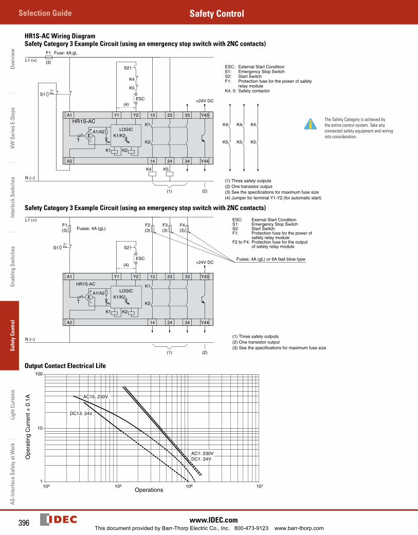
HR1S-AC Wiring DiagramSafety Category 3 Example Circuit (using an emergency stop switch with 2NC contacts)
ESC
S2
S1
K5K4
K4
K5
L1 (+)
N (–)
F1 Fuse: 4A gL
(3)
Y1
A2
A1 13 23
14 24
Y2
K2
K1
K2
33
34
Y43
Y44
HR1S-AC+
–
LOGIC
K1
A1/A2K1/K2
K4
K5
K4
K5
K4
K5T
(1) (2)
+24V DC(4)
ESC: External Start ConditionS1: Emergency Stop SwitchS2: Start SwitchF1: Protection fuse for the power of safety
relay moduleK4, 5: Safety contactor
(1) Three safety outputs(2) One transistor output(3) See the specifications for maximum fuse size(4) Jumper for terminal Y1-Y2 (for automatic start)
The Safety Category is achieved by the entire control system. Take any connected safety equipment and wiring into consideration.
Safety Category 3 Example Circuit (using an emergency stop switch with 2NC contacts)
ESC+24V DC
S2
L1 (+)
N (–)
F1(3)
Y1
A2
A1 13 23
14 24
Y2
K2
K1
K2
33
34
Y43
Y44
HR1S-AC
+
–
LOGIC
K1
A1/A2K1/K2
F4(3)
F3(3)
F2(3)
T
S1
(1) (2)
(4)
ESC: Exernal Start ConditionS1: Emergency Stop SwitchS2: Start SwitchF1: Protection fuse for the power of
safety relay moduleF2 to F4: Protection fuse for the output
of safety relay module
(1) Three safety outputs(2) One transistor output(3) See the specifications for maximum fuse size
Fuses: 4A (gL) or 6A fast blow type
Fuses: 4A (gL)
Output Contact Electrical Life100
10
1
AC15: 230V
AC1: 230VDC1: 24V
DC13: 24V
104 105 106 107
Operations
Ope
ratin
g C
urre
nt ×
0.1
A
This document provided by Barr-Thorp Electric Co., Inc. 800-473-9123 www.barr-thorp.com
397800-262-IDEC (4332) • USA & Canada
HR1S-ACSafety ControlOverview
XW Series E-Stops
Interlock Switches
Enabling Switches
Safety ControlLight Curtains
AS-Interface Safety at Work
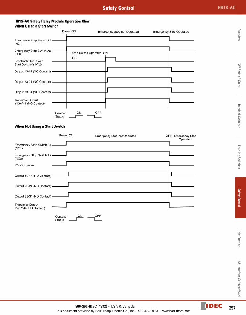
HR1S-AC Safety Relay Module Operation ChartWhen Using a Start Switch
ON
Emergency Stop OperatedEmergency Stop not Operated
Start Switch Operated
OFF
Emergency Stop Switch A1(NC1)
Emergency Stop Switch A2(NC2)
Feedback Circuit withStart Switch (Y1-Y2)
Output 13-14 (NO Contact)
Output 23-24 (NO Contact)
Output 33-34 (NO Contact)
Transistor OutputY43-Y44 (NO Contact)
ContactStatus
ON OFF
Power ON
When Not Using a Start Switch
Y1-Y2 Jumper
Emergency Stop Switch A1(NC1)
Emergency Stop Switch A2(NC2)
Output 13-14 (NO Contact)
Output 23-24 (NO Contact)
Output 33-34 (NO Contact)
Transistor OutputY43-Y44 (NO Contact)
ON OFF
Emergency StopOperated
Emergency Stop not OperatedPower ON OFF
ContactStatus
This document provided by Barr-Thorp Electric Co., Inc. 800-473-9123 www.barr-thorp.com
Over
view
XW S
erie
s E-
Stop
sIn
terlo
ck S
witc
hes
Enab
ling
Switc
hes
Safe
ty C
ontr
olLi
ght C
urta
ins
AS-In
terfa
ce S
afet
y at
Wor
kSelection Guide Safety Control
398 www.IDEC.com
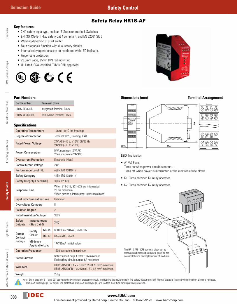
Safety Relay HR1S-AF Key features:
• 2NC safety input type, such as E-Stops or Interlock Switches• EN ISO 13849-1 PLe, Safety Cat 4 compliant, and EN 62061 SIL 3• Welding detection of start switch • Fault diagnosis function with dual safety circuits• Internal relay operations can be moni tored with LED Indicator.• Finger-safe protection• 22.5mm wide, 35mm DIN rail mounting• UL listed, CSA certified, TÜV NORD approved
Part NumbersPart Number Terminal Style
HR1S-AF5130B Integrated Terminal Block
HR1S-AF5130PB Removable Terminal Block
SpecificationsOperating Temperature –25 to +55°C (no freezing)
Degree of Protection Terminal: IP20, Housing: IP40
Rated Power Voltage 24V AC (–15 to +10%) 50/60 Hz24V DC (–15 to +10%)
Power Consumption 5 VA maximum (24V AC)2.5W maximum (24V DC)
Overcurrent Protection Electronic (Note)
Control Circuit Voltage 24V
Performance Level (PL) e (EN ISO 13849-1)
Safety Category 4 (EN ISO 13849-1)
Safety Integrity Level (SIL) 3 (EN 62061)
Response TimeWhen S11-S12, S21-S22 are interrupted: 20 ms maximumWhen power is interrupted: 60 ms maximum
Input Synchronization Time Unlimited
Overvoltage Category III
Pollution Degree 2
Rated Insulation Voltage 300V
Safety Outputs
Instantaneous (Stop Cat 0) 3NO
Output Contact Ratings
Safety Circuit
AC-15 C300: Ue= 240VAC, Ie=0.75A
DC-13 Ue=24VDC, Ie=2A
Minimum Applicable Load 17V/10mA (initial value)
Operation Frequency 1200 operations/h maximum
Rated Current Safety circuit output total: 18A maximumEach safety circuit output: 6A maximum
Wire Size HR1S-AF5130B: 1 × 2.5 mm2, 2 × 0.75 mm2 maximumHR1S-AF5130PB: 1 × 2.5 mm2, 2 × 1.5 mm2 maximum
Weight 250g
Note: Short-circuit of S11 and S21 activates the overcurrent protection circuit, interrupting the power supply. The safety output turns off. Normal status is restored when the short-circuit is removed. Use a 4A fuse (Type gL) for power line protection. Use a 4A fuse (Type gL) or a 6A fast blow fuse for output line protection.
Dimensions (mm) Terminal Arrangement
11422.5
99
A1/A2FuseK1K2
LED Indicator
• A1/A2 Fuse: Turns on when power circuit is normal. Turns off when power is interrupted or the electronic fuse blows.
• K1: Turns on when K1 relay operates.
• K2: Turns on when K2 relay operates.
The HR1S-AF5130PB terminal block can be removed and installed as shown, allowing for easy installation and replacement of modules.
This document provided by Barr-Thorp Electric Co., Inc. 800-473-9123 www.barr-thorp.com
399800-262-IDEC (4332) • USA & Canada
HR1S-ACSafety ControlOverview
XW Series E-Stops
Interlock Switches
Enabling Switches
Safety ControlLight Curtains
AS-Interface Safety at Work
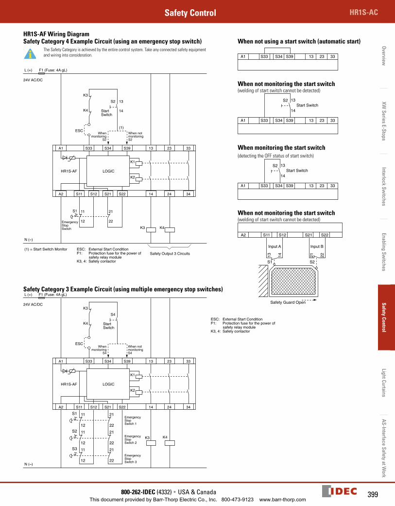
HR1S-AF Wiring DiagramSafety Category 4 Example Circuit (using an emergency stop switch) When not using a start switch (automatic start)
The Safety Category is achieved by the entire control system. Take any connected safety equipment and wiring into consideration.
A1 S33 S34 S39
(1)
13 23 33
A2 S11
S1
S2 13
14
11
12
21
22
K3
Safety Output 3 Circuits
K1
K2
K3
F1 (Fuse: 4A gL)L (+)
N (–)
(1) = Start Switch Monitor ESC: External Start ConditionF1: Protection fuse for the power of
safety relay moduleK3, 4: Safety contactor
K4
ESC
LOGICHR1S-AF
24V AC/DC
StartSwitch
Whenmonitoring
S2
When notmonitoringS2
EmergencyStopSwitch K4
S12 S21 S22 14 24 34
A1 S33 S34 S39 13 23 33
When not monitoring the start switch(welding of start switch cannot be detected)
A1 S33
S2
S34 S39 13
13
14
23 33
Start Switch
When monitoring the start switch(detecting the OFF status of start switch)
A1 S33
S2
S34 S39 13
13
14
23 33
Start Switch
When not monitoring the start switch(welding of start switch cannot be detected)
A2 S11
S1 S2
Safety Guard Open
13 14
S12 S21 S22
21 22
Input A Input B
Safety Category 3 Example Circuit (using multiple emergency stop switches)
A1 S33 S34 S39 13 23 33
A2 S11
S4
K3
K1
K2
K3
F1 (Fuse: 4A gL)L (+)
N (–)
K4
ESC
LOGICHR1S-AF
24V AC/DC
K4
S12 S21 S22 14 24 34
StartSwitch
Whenmonitoring
S4
When notmonitoringS4
EmergencyStopSwitch 1
EmergencyStopSwitch 2
EmergencyStopSwitch 3
12
11
22
21
22
21
22
21
S1
12
11S2
12
11S3
ESC: External Start ConditionF1: Protection fuse for the power of
safety relay moduleK3, 4: Safety contactor
This document provided by Barr-Thorp Electric Co., Inc. 800-473-9123 www.barr-thorp.com
Over
view
XW S
erie
s E-
Stop
sIn
terlo
ck S
witc
hes
Enab
ling
Switc
hes
Safe
ty C
ontr
olLi
ght C
urta
ins
AS-In
terfa
ce S
afet
y at
Wor
kSelection Guide Safety Control
400 www.IDEC.com
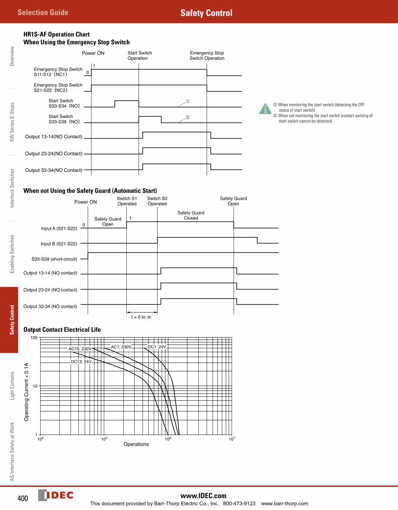
HR1S-AF Operation ChartWhen Using the Emergency Stop Switch
Emergency Stop SwitchS11-S12 NC1
Emergency Stop SwitchS21-S22 NC2
Start SwitchS33-S34 NO
Start SwitchS33-S39 NO
➀
➁
10
Start SwitchOperation
Emergency StopSwitch Operation
Output 13-14(NO Contact)
Output 23-24(NO Contact)
Output 33-34(NO Contact)
Power ON
j When monitoring the start switch (detecting the OFF status of start switch)
k When not monitoring the start switch (contact welding of start switch can not be detected)
When not Using the Safety Guard (Automatic Start)
Input A (S21-S22)
Input B (S21-S22)
S33-S39 (short-circuit)
Safety GuardOpen
t = 0 to ∞
Safety GuardClosed
Switch S1Operated
Switch S2Operated
Safety GuardOpen
1
0
Output 13-14 (NO contact)
Output 23-24 (NO contact)
Output 33-34 (NO contact)
Power ON
Output Contact Electrical Life100
10
1104 105 106 107
AC15: 230V
DC13: 24V
AC1: 230V DC1: 24V
Operations
Ope
ratin
g C
urre
nt ×
0.1
A
This document provided by Barr-Thorp Electric Co., Inc. 800-473-9123 www.barr-thorp.com
401800-262-IDEC (4332) • USA & Canada
HR1S-ACSafety ControlOverview
XW Series E-Stops
Interlock Switches
Enabling Switches
Safety ControlLight Curtains
AS-Interface Safety at Work
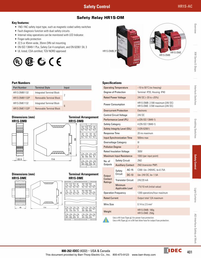
Safety Relay HR1S-DM Key features:
• 1NO-1NC safety input type, such as magnetic coded safety switches• Fault diagnosis function with dual safety circuits.• Internal relay operations can be moni tored with LED Indicator.• Finger-safe protection• 22.5 or 45mm wide, 35mm DIN rail mounting• EN ISO 13849-1 PLe, Safety Cat 4 compliant, and EN 62061 SIL 3• UL listed, CSA certified, TÜV NORD approved
HR1S-DMB( )P
HR1S-DMBHR1S-DME
Part NumbersPart Number Terminal Style Input
HR1S-DMB1132 Integrated Terminal Block2
HR1S-DMB1132P Removable Terminal Block
HR1S-DME1132 Integrated Terminal Block6
HR1S-DME1132P Removable Terminal Block
Dimensions (mm) Terminal ArrangementHR1S-DMB HR1S-DMB
22.5 114
99
HR1S-DMB1132 HR1S-DMB1132P
S11 S12 S13 23A1 Y1 Y2 13
S21 S22 S23 24A2 Y34 Y44 14
A1 Y1 Y2 13
S21 S22 S23 24
A2 Y34 Y44 14
S11 S12 S13 23
Dimensions (mm) Terminal ArrangementHR1S-DME HR1S-DME
114
99
45
HR1S-DME1132 HR1S-DME1132P
SpecificationsOperating Temperature –10 to 55°C (no freezing)
Degree of Protection Terminal: IP20, Housing: IP40
Rated Power Voltage 24V DC (–20 to +20%)
Power Consumption HR1S-DMB: 2.5W maximum (24V DC)HR1S-DME: 3.5W maximum (24V DC)
Overcurrent Protection Electronic
Control Circuit Voltage 24V DC
Performance Level (PL) e (EN ISO 13849-1)
Safety Category 4 (EN ISO 13849-1)
Safety Integrity Level (SIL) 3 (EN 62061)
Response Time 20 ms maximum
Input Synchronization Time 500ms max
Overvoltage Category III
Pollution Degree 2
Rated Insulation Voltage 300V
Maximum Input Resistance 100Ω (per input point)
No. of Outputs
Safety Circuit 2NO
Auxilliary Contact 2NO (transistor PNP)
Output Contact Ratings
Safety Circuit
AC-15 C300: Ue= 240VAC, Ie=0.75A
DC-13 Ue= 24V DC, Ie= 1.5A
Transistor Circuit 24V/20 mA
Minimum Applicable Load 17V/10 mA (initial value)
Operation Frequency 1200 operations/hour maximum
Rated Current Output total 12A maximum
Wire Size 0.14 to 2.5 mm2
Weight HR1S-DMB: 180gHR1S-DME: 250g
Use a 4A fuse (Type gL) for power fuse protection. Use a 4A (Type gL) or a 6A fast blow fuse for output fuse protection.
This document provided by Barr-Thorp Electric Co., Inc. 800-473-9123 www.barr-thorp.com
Over
view
XW S
erie
s E-
Stop
sIn
terlo
ck S
witc
hes
Enab
ling
Switc
hes
Safe
ty C
ontr
olLi
ght C
urta
ins
AS-In
terfa
ce S
afet
y at
Wor
kSelection Guide Safety Control
402 www.IDEC.com
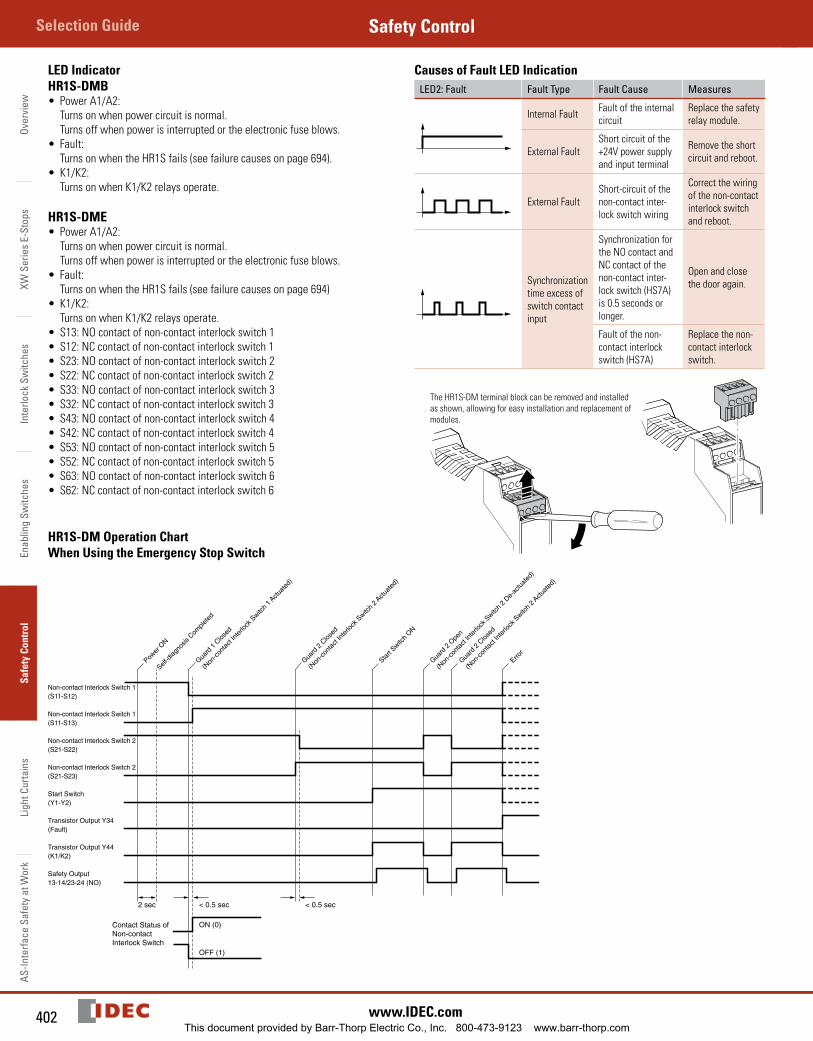
LED IndicatorHR1S-DMB• Power A1/A2:
Turns on when power circuit is normal. Turns off when power is interrupted or the electronic fuse blows.
• Fault: Turns on when the HR1S fails (see failure causes on page 694).
• K1/K2: Turns on when K1/K2 relays operate.
HR1S-DME• Power A1/A2:
Turns on when power circuit is normal. Turns off when power is interrupted or the electronic fuse blows.
• Fault: Turns on when the HR1S fails (see failure causes on page 694)
• K1/K2: Turns on when K1/K2 relays operate.
• S13: NO contact of non-contact interlock switch 1• S12: NC contact of non-contact interlock switch 1• S23: NO contact of non-contact interlock switch 2• S22: NC contact of non-contact interlock switch 2• S33: NO contact of non-contact interlock switch 3• S32: NC contact of non-contact interlock switch 3• S43: NO contact of non-contact interlock switch 4• S42: NC contact of non-contact interlock switch 4• S53: NO contact of non-contact interlock switch 5• S52: NC contact of non-contact interlock switch 5• S63: NO contact of non-contact interlock switch 6• S62: NC contact of non-contact interlock switch 6
Causes of Fault LED IndicationLED2: Fault Fault Type Fault Cause Measures
Internal Fault Fault of the internal circuit
Replace the safety relay module.
External FaultShort circuit of the +24V power supply and input terminal
Remove the short circuit and reboot.
External FaultShort-circuit of the non-contact inter-lock switch wiring
Correct the wiring of the non-contact interlock switch and reboot.
Synchronization time excess of switch con tact input
Synchronization for the NO contact and NC con tact of the non-contact inter-lock switch (HS7A) is 0.5 seconds or longer.
Open and close the door again.
Fault of the non-contact interlock switch (HS7A)
Replace the non-contact interlock switch.
The HR1S-DM terminal block can be removed and installed as shown, allowing for easy installation and replacement of modules.
HR1S-DM Operation ChartWhen Using the Emergency Stop Switch
Non-contact Interlock Switch 1(S11-S12)
Contact Status ofNon-contactInterlock Switch
Non-contact Interlock Switch 1(S11-S13)
Non-contact Interlock Switch 2(S21-S22)
Non-contact Interlock Switch 2(S21-S23)
Start Switch(Y1-Y2)
Transistor Output Y34(Fault)
Transistor Output Y44(K1/K2)
Safety Output13-14/23-24 (NO)
< 0.5 sec2 sec
OFF (1)
ON (0)
< 0.5 sec
Power
ON
Self-d
iagno
sis C
omple
ted
Guard
1 C
losed
(Non
-con
tact
Inte
rlock
Switc
h 1 A
ctuat
ed)
Guard
2 C
losed
(Non
-con
tact
Inte
rlock
Switc
h 2 A
ctuat
ed)
Start
Switch
ON
Guard
2 O
pen
(Non
-con
tact
Inte
rlock
Switc
h 2
De-ac
tuat
ed)
Guard
2 C
losed
(Non
-con
tact
Inte
rlock
Switc
h 2 A
ctuat
ed)
Error
This document provided by Barr-Thorp Electric Co., Inc. 800-473-9123 www.barr-thorp.com
403800-262-IDEC (4332) • USA & Canada
HR1S-ACSafety ControlOverview
XW Series E-Stops
Interlock Switches
Enabling Switches
Safety ControlLight Curtains
AS-Interface Safety at Work
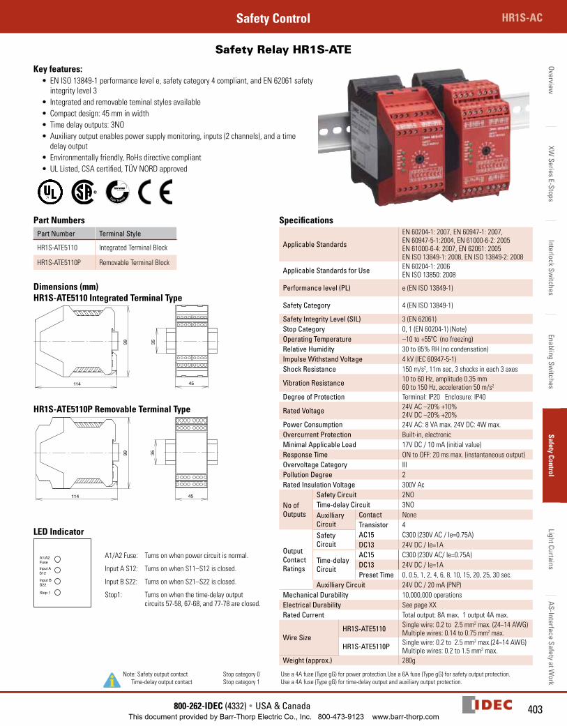
Safety Relay HR1S-ATE
Key features:• EN ISO 13849-1 performance level e, safety category 4 compliant, and EN 62061 safety
integrity level 3• Integrated and removable teminal styles available• Compact design: 45 mm in width• Time delay outputs: 3NO• Auxiliary output enables power supply monitoring, inputs (2 channels), and a time
delay output• Environmentally friendly, RoHs directive compliant• UL Listed, CSA certified, TÜV NORD approved
Part NumbersPart Number Terminal Style
HR1S-ATE5110 Integrated Terminal Block
HR1S-ATE5110P Removable Terminal Block
Dimensions (mm)HR1S-ATE5110 Integrated Terminal Type
HR1S-ATE5110P Removable Terminal Type
LED Indicator
A1/A2FuseInput AS12
Input BS22
Stop 1
A1/A2 Fuse: Turns on when power circuit is normal.
Input A S12: Turns on when S11–S12 is closed.
Input B S22: Turns on when S21–S22 is closed.
Stop1: Turns on when the time-delay output circuits 57-58, 67-68, and 77-78 are closed.
Specifications
Applicable Standards
EN 60204-1: 2007, EN 60947-1: 2007, EN 60947-5-1:2004, EN 61000-6-2: 2005EN 61000-6-4: 2007, EN 62061: 2005EN ISO 13849-1: 2008, EN ISO 13849-2: 2008
Applicable Standards for Use EN 60204-1: 2006EN ISO 13850: 2008
Performance level (PL) e (EN ISO 13849-1)
Safety Category 4 (EN ISO 13849-1)
Safety Integrity Level (SIL) 3 (EN 62061)Stop Category 0, 1 (EN 60204-1) (Note)Operating Temperature –10 to +55ºC (no freezing)Relative Humidity 30 to 85% RH (no condensation)Impulse Withstand Voltage 4 kV (IEC 60947-5-1)Shock Resistance 150 m/s2, 11m sec, 3 shocks in each 3 axes
Vibration Resistance 10 to 60 Hz, amplitude 0.35 mm60 to 150 Hz, acceleration 50 m/s2
Degree of Protection Terminal: IP20 Enclosure: IP40
Rated Voltage 24V AC –20% +10%24V DC –20% +20%
Power Consumption 24V AC: 8 VA max. 24V DC: 4W max.Overcurrent Protection Built-in, electronicMinimal Applicable Load 17V DC / 10 mA (initial value)Response Time ON to OFF: 20 ms max. (instantaneous output)Overvoltage Category IIIPollution Degree 2Rated Insulation Voltage 300V Ac
No of Outputs
Safety Circuit 2NOTime-delay Circuit 3NOAuxilliary Circuit
Contact NoneTransistor 4
Output Contact Ratings
Safety Circuit
AC15 C300 (230V AC / Ie=0.75A)DC13 24V DC / Ie=1A
Time-delay Circuit
AC15 C300 (230V AC/ Ie=0.75A)DC13 24V DC / Ie=1APreset Time 0, 0.5, 1, 2, 4, 6, 8, 10, 15, 20, 25, 30 sec.
Auxilliary Circuit 24V DC / 20 mA (PNP)Mechanical Durability 10,000,000 operationsElectrical Durability See page XXRated Current Total output: 8A max. 1 output 4A max.
Wire SizeHR1S-ATE5110 Single wire: 0.2 to 2.5 mm2 max. (24~14 AWG)
Multiple wires: 0.14 to 0.75 mm2 max.
HR1S-ATE5110P Single wire: 0.2 to 2.5 mm2 max.(24~14 AWG)Multiple wires: 0.2 to 1.5 mm2 max.
Weight (approx.) 280g
Note: Safety output contact Stop category 0 Time-delay output contact Stop category 1
Use a 4A fuse (Type gG) for power protection.Use a 6A fuse (Type gG) for safety output protection.Use a 4A fuse (Type gG) for time-delay output and auxiliary output protection.
114
9999 35
35
114 45
45
This document provided by Barr-Thorp Electric Co., Inc. 800-473-9123 www.barr-thorp.com
Over
view
XW S
erie
s E-
Stop
sIn
terlo
ck S
witc
hes
Enab
ling
Switc
hes
Safe
ty C
ontr
olLi
ght C
urta
ins
AS-In
terfa
ce S
afet
y at
Wor
kSelection Guide Safety Control
404 www.IDEC.com
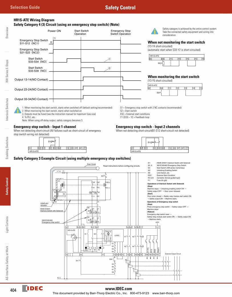
HR1S-ATE Wiring DiagramSafety Category 4 (3) Circuit (using an emergency stop switch) (Note)
Emergency Stop SwitchS11-S12 NC1
Emergency Stop SwitchS21-S22 NC2
Start SwitchS33-S34 NO
Start SwitchS33-S39 NO
➀
➁
10
Start SwitchOperation
Emergency StopSwitch Operation
Output 13-14(NO Contact)
Output 23-24(NO Contact)
Output 33-34(NO Contact)
Power ON Safety category is achieved by the entire control system.
Take the connected safety equipment and wiring into consideration.
When not monitoring the start switch(Y3-Y4 short-circuited) (automatic start when S33-Y2 is short-circuited)
HR1S-ATE
When monitoring the start switch(Y3-Y5 short-circuited)HR1S-ATE
1. When monitoring the start switch, starts when switched off (default setting/recommended)2. When monitoring the start switch, starts when switched on3. Outputs must be fused (see the instruction manual for maximum fuse size)4. To PLC, etc.Note: When using off-delay output, safety category becomes 3.
S1 = Emergency stop switch with 2 NC contacts (recommended)S2 = Start switchESC = External start conditionsY1 (S33) – Y2 = Feedback loop
Emergency stop switch - Input 1 channel When not detecting short-circuit (All failures such as short-circuit of emergency stop switch wiring not detected)
HR1S-ATE
Emergency stop switch - Input 2 channelsWhen not detecting short-circuit(B1-S12 short-circuit not detected)
HR1S-ATE
Safety Category 3 Example Circuit (using multiple emergency stop switches)
S4
S11S21A1 13 57 67
A2 S33 Y1 Y2 Y3 Y4 Y5 14 24 6858
S22B1 S12 23
K2 K4 K1
K1
K3
N (–)
K3
K4
K1
K2
Tim
er 1
Time (s)
Timer
2
T
ESC
K1K2K3K4
HR1S-ATE
LOGIC
77
78 Y88 Y89 Y90 Y91
Y+
(A1/
A2)
(S12
)
(S22
)
(Sto
p1)
+24V
K2
L1 (+) F1
S3 21
22
11
12
S221
22
11
12
A2(+)
22
2111
42
A1(–)
S1
2
1
12S5
S6
52
41 51
12
Door Cover
K5K6K7K8
K5
K6
K7
K8
External Output Circuit
S1: HS5E-D4001 Interlock Switch with SolenoidS2, 3: XW1E-BV402 Emergency Stop SwitchS4: Start Switch (HW series momentary)S5: Unlocking Enabling SwitchS6: Limit Switch, etc.ESC: External Start ConditionK5 to 8: Contactor (forced guided type)F1: Fuse 4A (gG)
Operations of Interlock Switch with Solenoid(Stop)Machine stops → Unlocking enabling switch ON →
Safety output OFF → Door cover released(Start)Door cover closed → Safety relay module start switch ON → Safety output ON → Machine starts
Operations of Emergency stop switch(Stop)Press emergency stop switch → Safety output OFF →
Machine stops(Reboot)Emergency stop switch reset → Safety relay module start switch ON → Safety output ON → Machine starts
Read instructions before configuring circuits.
HS5E-D4001Interlock Switch with Solenoid
XW1E-BV402Emergency stop switch
HS9Z-A51Actuator
This document provided by Barr-Thorp Electric Co., Inc. 800-473-9123 www.barr-thorp.com
405800-262-IDEC (4332) • USA & Canada
HR1S-ACSafety ControlOverview
XW Series E-Stops
Interlock Switches
Enabling Switches
Safety ControlLight Curtains
AS-Interface Safety at Work
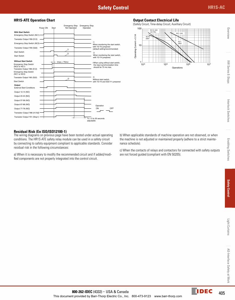
HR1S-ATE Operation Chart
Power ON
With Start Switch
Output
Emergency Stop Switch (NC1)
➀
➀When monitoring the start switch,with Y3-Y5 jumpered(default setting/recommended)
OperationON
Tv = 0 to 30 secondsadjustable
OFF
➁When monitoring the start switch,with Y3-Y4 jumpered
➁
Emergency Stop Switch (NC2)
Output 13-14 (NO)
Output 23-24 (NO)
Output 57-58 (NO)
Output 67-68 (NO)
Output 77-78 (NO)
Start Switch
Start Switch
Start Switch
External Start Conditions
Transistor Output Y89 (S12)
Transistor Output Y89 (S12)
Transistor Output Y90 (S22)
Transistor Output Y90 (S22)
Transistor Output Y88 (A1/A2)
Transistor Output Y91 (Stop1)
StartEmergency Stop
Not OperatedEmergency Stop
Operated
Without Start SwitchEmergency Stop Switch(NC2 or NC1)
Emergency Stop Switch(NC1 or NC2)
tmax.= 75ms∗
➂➂Without start switch, with Y3-Y4 and S33-Y1 jumpered
∗When using without start switch, the input synchronization time should be 75 ms max.
Output Contact Electrical Life(Safety Circuit, Time-delay Circuit, Auxilliary Circuit)
Ope
ratin
g C
urre
nt ×
0.1
A
Operations
AC15:230V
AC1:230V
DC1: 24V
DC13: 24V(<0,1Hz)
Residual Risk (En ISO/ISO12100-1)The wiring diagrams on previous page have been tested under actual operating conditions. The HR1S-ATE safety relay module can be used in a safety circuit by connecting to safety equipment compliant to applicable standards. Consider residual risk in the following circumstances:
a) When it is necessary to modify the recommended circuit and if added/modi-fied components are not properly integrated into the control circuit.
b) When applicable standards of machine operation are not observed, or when the machine is not adjusted or maintained properly (adhere to a strict mainte-nance schedule).
c) When the contacts of relays and contactors for connected with safety outputs are not forced guided (compliant with EN 50205).
This document provided by Barr-Thorp Electric Co., Inc. 800-473-9123 www.barr-thorp.com
Over
view
XW S
erie
s E-
Stop
sIn
terlo
ck S
witc
hes
Enab
ling
Switc
hes
Safe
ty C
ontr
olLi
ght C
urta
ins
AS-In
terfa
ce S
afet
y at
Wor
kSelection Guide Safety Control
406 www.IDEC.com
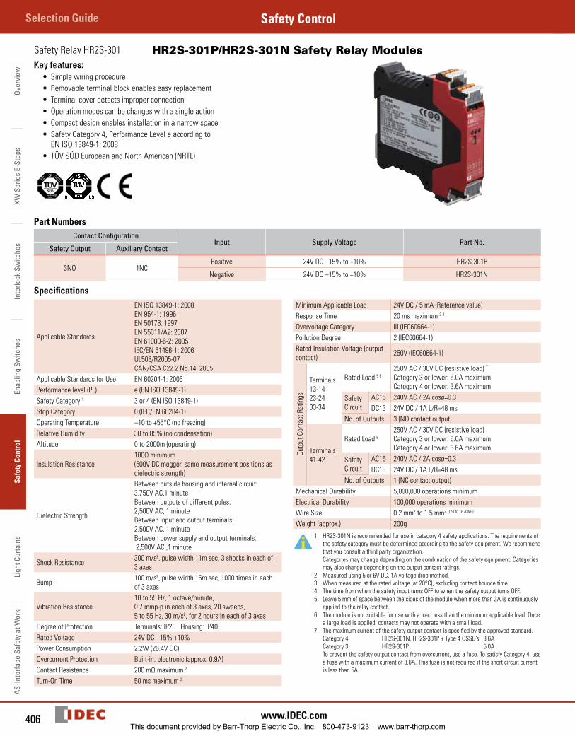
HR2S-301P/HR2S-301N Safety Relay Modules Key features:
• Simple wiring procedure• Removable terminal block enables easy replacement• Terminal cover detects improper connection• Operation modes can be changes with a single action• Compact design enables installation in a narrow space• Safety Category 4, Performance Level e according to
EN ISO 13849-1: 2008• TÜV SÜD European and North American (NRTL)
FunctionalSafety
Production
monitoredSafety
tested
Part NumbersContact Configuration
Input Supply Voltage Part No.Safety Output Auxiliary Contact
3NO 1NCPositive 24V DC –15% to +10% HR2S-301P
Negative 24V DC –15% to +10% HR2S-301N
Specifications
Applicable Standards
EN ISO 13849-1: 2008EN 954-1: 1996EN 50178: 1997EN 55011/A2: 2007EN 61000-6-2: 2005IEC/EN 61496-1: 2006UL508/R2005-07 CAN/CSA C22.2 No.14: 2005
Applicable Standards for Use EN 60204-1: 2006Performance level (PL) e (EN ISO 13849-1)Safety Category 1 3 or 4 (EN ISO 13849-1)Stop Category 0 (IEC/EN 60204-1)Operating Temperature –10 to +55°C (no freezing)Relative Humidity 30 to 85% (no condensation)Altitude 0 to 2000m (operating)
Insulation Resistance100Ω minimum (500V DC megger, same measurement positions as dielectric strength)
Dielectric Strength
Between outside housing and internal circuit: 3,750V AC,1 minuteBetween outputs of different poles: 2,500V AC, 1 minuteBetween input and output terminals: 2,500V AC, 1 minuteBetween power supply and output terminals: 2,500V AC ,1 minute
Shock Resistance 300 m/s2, pulse width 11m sec, 3 shocks in each of 3 axes
Bump 100 m/s2, pulse width 16m sec, 1000 times in each of 3 axes
Vibration Resistance10 to 55 Hz, 1 octave/minute, 0.7 mmp-p in each of 3 axes, 20 sweeps,5 to 55 Hz, 30 m/s2, for 2 hours in each of 3 axes
Degree of Protection Terminals: IP20 Housing: IP40Rated Voltage 24V DC –15% +10%Power Consumption 2.2W (26.4V DC)Overcurrent Protection Built-in, electronic (approx. 0.9A)Contact Resistance 200 mΩ maximum 2
Turn-On Time 50 ms maximum 3
Minimum Applicable Load 24V DC / 5 mA (Reference value)Response Time 20 ms maximum 3 4
Overvoltage Category III (IEC60664-1)Pollution Degree 2 (IEC60664-1)Rated Insulation Voltage (output contact) 250V (IEC60664-1)
Outp
ut C
onta
ct R
atin
gs
Terminals13-1423-2433-34
Rated Load 5 6250V AC / 30V DC (resistive load) 7
Category 3 or lower: 5.0A maximumCategory 4 or lower: 3.6A maximum
Safety Circuit
AC15 240V AC / 2A cosø=0.3DC13 24V DC / 1A L/R=48 ms
No. of Outputs 3 (NO contact output)
Terminals41-42
Rated Load 6250V AC / 30V DC (resistive load)Category 3 or lower: 5.0A maximumCategory 4 or lower: 3.6A maximum
Safety Circuit
AC15 240V AC / 2A cosø=0.3DC13 24V DC / 1A L/R=48 ms
No. of Outputs 1 (NC contact output)Mechanical Durability 5,000,000 operations minimumElectrical Durability 100,000 operations minimumWire Size 0.2 mm2 to 1.5 mm2 (24 to 16 AWG)
Weight (approx.) 200g
1. HR2S-301N is recommended for use in category 4 safety applications. The requirements of the safety category must be determined according to the safety equipment. We recommend that you consult a third party organization. Categories may change depending on the combination of the safety equipment. Categories may also change depending on the output contact ratings.
2. Measured using 5 or 6V DC, 1A voltage drop method.3. When measured at the rated voltage (at 20°C), excluding contact bounce time.4. The time from when the safety input turns OFF to when the safety output turns OFF.5. Leave 5 mm of space between the sides of the module when more than 3A is continuously
applied to the relay contact.6. The module is not suitable for use with a load less than the minimum applicable load. Once
a large load is applied, contacts may not operate with a small load.7. The maximum current of the safety output contact is specified by the approved standard.
Category 4 HR2S-301N, HR2S-301P + Type 4 OSSD’s 3.6A Category 3 HR2S-301P 5.0A
To prevent the safety output contact from overcurrent, use a fuse. To satisfy Category 4, use a fuse with a maximum current of 3.6A. This fuse is not required if the short circuit current is less than 5A.
Safety Relay HR2S-301
HR2S-301
This document provided by Barr-Thorp Electric Co., Inc. 800-473-9123 www.barr-thorp.com
407800-262-IDEC (4332) • USA & Canada
HR1S-ACSafety ControlOverview
XW Series E-Stops
Interlock Switches
Enabling Switches
Safety ControlLight Curtains
AS-Interface Safety at Work
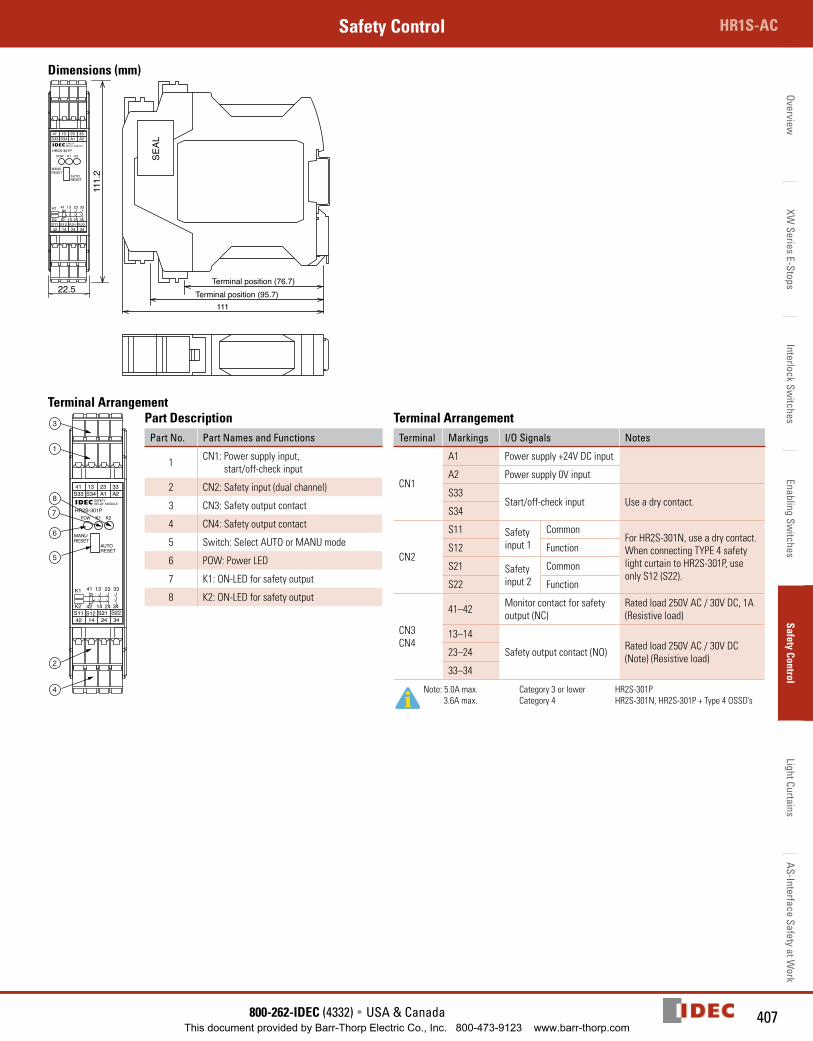
Dimensions (mm)
Terminal position (95.7)Terminal position (76.7)
22.5
111
13 23 3341S34S33 A2A1
14 24 3442S11 S12 S21 S22
AUTORESET
MANURESET
POW K1 K2
K1
K2
23
24
33
34
13
14
41
42
SAFETYRELAY MODULE
HR2S-301P
111.
2
SEAL
Terminal Arrangement
41 13 23 33S34S33Y2Y1
HR2S-301PSAFETYRELAY MODULE
K2K1POW
MANURESET
AUTORESET
42 14 24 34S22S21S12S11
K2
K1 41 13 23 33
42 14 24 34
1
2
3
4
7
8
6
5
1
2
3
4
7
8
6
5
13 23 3341S34S33 A2A1
AUTORESET
MANURESET
POW K1 K2
SAFETYRELAY MODULE
HR2S-301P
13 23 3341S34S33 A2A1
14 24 3442S11 S12 S21 S22
AUTORESET
MANURESET
POW K1 K2
K1
K2
23
24
33
34
13
14
41
42
SAFETYRELAY MODULE
HR2S-301P
42 14 24 34S22S21S12S11
K2
K1 41 13 23 33
42 14 24 34
Part DescriptionPart No. Part Names and Functions
1 CN1: Power supply input, start/off-check input
2 CN2: Safety input (dual channel)
3 CN3: Safety output contact
4 CN4: Safety output contact
5 Switch: Select AUTO or MANU mode
6 POW: Power LED
7 K1: ON-LED for safety output
8 K2: ON-LED for safety output
Terminal ArrangementTerminal Markings I/O Signals Notes
CN1
A1 Power supply +24V DC input
A2 Power supply 0V input
S33Start/off-check input Use a dry contact.
S34
CN2
S11 Safety input 1
Common For HR2S-301N, use a dry contact.When connecting TYPE 4 safety light curtain to HR2S-301P, use only S12 (S22).
S12 Function
S21 Safety input 2
Common
S22 Function
CN3CN4
41–42 Monitor contact for safety output (NC)
Rated load 250V AC / 30V DC, 1A(Resistive load)
13–14
Safety output contact (NO) Rated load 250V AC / 30V DC (Note) (Resistive load)23–24
33–34
Note: 5.0A max. Category 3 or lower HR2S-301P 3.6A max. Category 4 HR2S-301N, HR2S-301P + Type 4 OSSD’s
This document provided by Barr-Thorp Electric Co., Inc. 800-473-9123 www.barr-thorp.com
Over
view
XW S
erie
s E-
Stop
sIn
terlo
ck S
witc
hes
Enab
ling
Switc
hes
Safe
ty C
ontr
olLi
ght C
urta
ins
AS-In
terfa
ce S
afet
y at
Wor
kSelection Guide Safety Control
408 www.IDEC.com
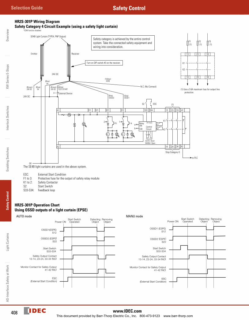
HR2S-301P Wiring DiagramSafety Category 4 Circuit Example (using a safety light curtain)
Emitter
24V DC
External Device
N.C. (No Connect)
Receiver
SE4B Light Curtain (TYPE4, PNP Output)
K2
2 b
ESCS2
K2
K1
S34
AUTO: ShortMANU: Open
S33
ControlCircuit
Off CheckRelayONSubb
aa1
S12S22S21S11
0V
24V DC
A2
A1
K1
13
14 24
23 33
34 42
41
K1
K2
(1)
Stop Category 0
to PLC
Turn on DIP switch #3 on the receiver.
(White) TEST/START
(Brown)24V DC
(Blue)0V
(Blue)0V
(Brown)24V DC
(Yellow)EDM
(Pink)OSSD2
(Gray)OSSD1
K1
K2
13 23 33
14 24 34
F1 F2 F3(1) (1) (1)
(1) Use a 3.6A maximum fuse for output line protection.
The SE4B light curtains are used in the above system.
ESC: External Start ConditionF1 to 3: Protective fuse for the output of safety relay moduleK1 to 2: Safety ContactorS2: Start SwitchS33-S34: Feedback loop
Safety category is achieved by the entire control system. Take the connected safety equipment and wiring into consideration.
*EDM function disabled
HR2S-301P Operation Chart Using OSSD outputs of a light curtain (EPSE)
AUTO mode MANU mode
This document provided by Barr-Thorp Electric Co., Inc. 800-473-9123 www.barr-thorp.com
409800-262-IDEC (4332) • USA & Canada
HR1S-ACSafety ControlOverview
XW Series E-Stops
Interlock Switches
Enabling Switches
Safety ControlLight Curtains
AS-Interface Safety at Work
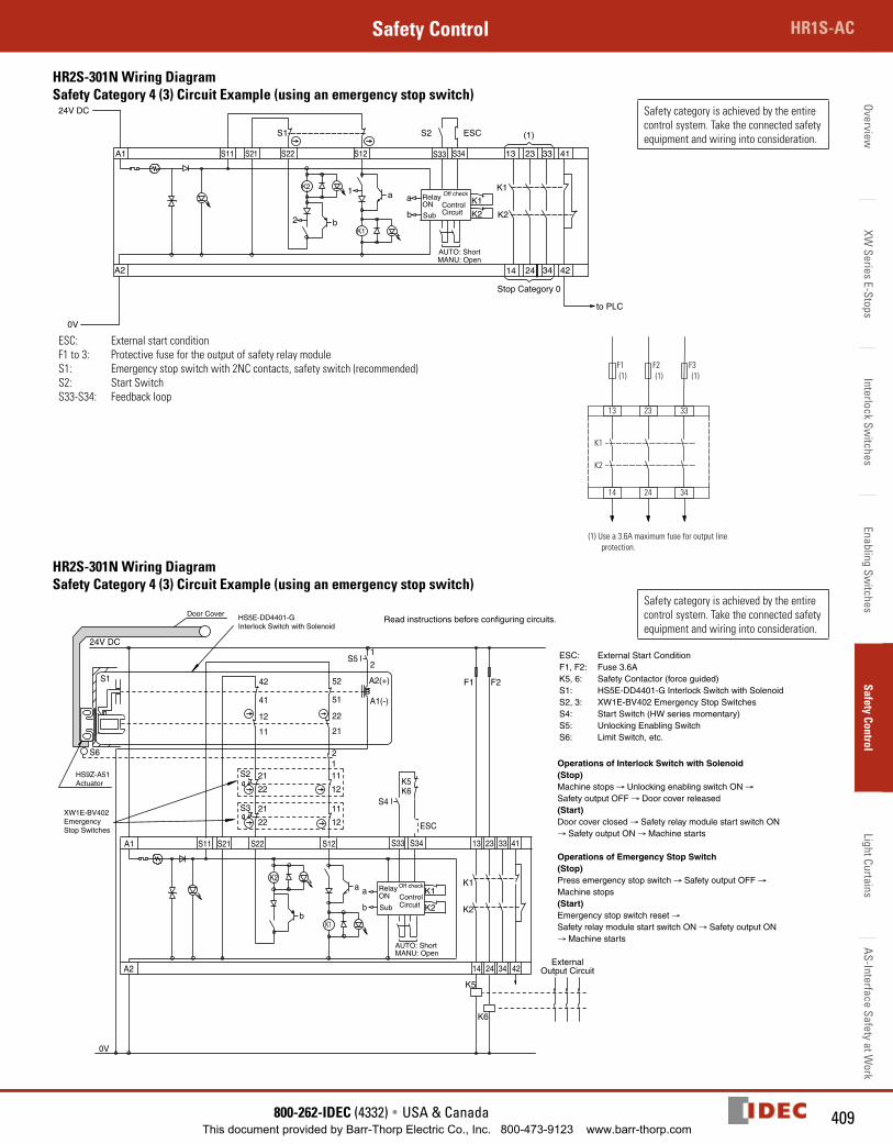
HR2S-301N Wiring DiagramSafety Category 4 (3) Circuit Example (using an emergency stop switch)
ESCS2
K2K1
S34
AUTO: ShortMANU: Open
S33
ControlCircuit
Off checkRelay ONSubb
aa1
2 b
S12S22
S1
S21S11
0V
24V DC
A2
K2
A1
K1
13
(1)
14 24
23 33
34 42
41
K1
K2
to PLC
Stop Category 0
Safety category is achieved by the entire control system. Take the connected safety equipment and wiring into consideration.
ESC: External start conditionF1 to 3: Protective fuse for the output of safety relay moduleS1: Emergency stop switch with 2NC contacts, safety switch (recommended) S2: Start SwitchS33-S34: Feedback loop
K1
K2
13 23 33
14 24 34
F1 F2 F3(1) (1) (1)
(1) Use a 3.6A maximum fuse for output line protection.
HR2S-301N Wiring DiagramSafety Category 4 (3) Circuit Example (using an emergency stop switch)
0V
K6K5
ESC
S4S3 21
22 12
11
11
1222
21S212
K2
K1
41
4234
3323
2414
13
K1
A1
K2
A2
S11 S21 S22 S12
b
a a
b
RelayON
Sub
Off check
ControlCircuit
S33 S34
K1
K2
A1(-)
A2(+)
21
S5
52
51
22
2111
12
41
42
S6
ExternalOutput Circuit
K6
K5
S1
24V DC
AUTO: ShortMANU: Open
F1 F2
ESC: External Start ConditionF1, F2: Fuse 3.6AK5, 6: Safety Contactor (force guided)S1: HS5E-DD4401-G Interlock Switch with SolenoidS2, 3: XW1E-BV402 Emergency Stop SwitchesS4: Start Switch (HW series momentary)S5: Unlocking Enabling SwitchS6: Limit Switch, etc.
Operations of Interlock Switch with Solenoid(Stop) Machine stops → Unlocking enabling switch ON → Safety output OFF → Door cover released(Start)Door cover closed → Safety relay module start switch ON → Safety output ON → Machine starts
Operations of Emergency Stop Switch(Stop)Press emergency stop switch → Safety output OFF → Machine stops(Start)Emergency stop switch reset → Safety relay module start switch ON → Safety output ON → Machine starts
HS5E-DD4401-GInterlock Switch with Solenoid
XW1E-BV402Emergency Stop Switches
HS9Z-A51Actuator
Door CoverRead instructions before configuring circuits.
Safety category is achieved by the entire control system. Take the connected safety equipment and wiring into consideration.
This document provided by Barr-Thorp Electric Co., Inc. 800-473-9123 www.barr-thorp.com
Over
view
XW S
erie
s E-
Stop
sIn
terlo
ck S
witc
hes
Enab
ling
Switc
hes
Safe
ty C
ontr
olLi
ght C
urta
ins
AS-In
terfa
ce S
afet
y at
Wor
kSelection Guide Safety Control
410 www.IDEC.com
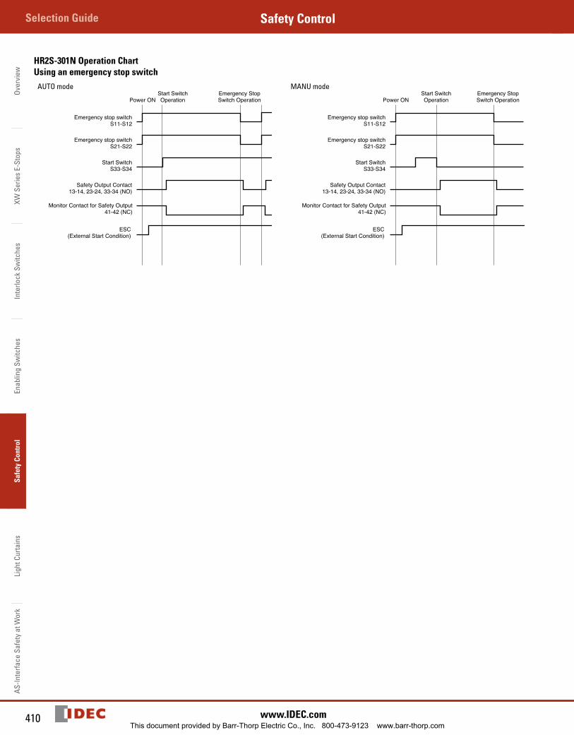
HR2S-301N Operation ChartUsing an emergency stop switch
AUTO mode
Emergency stop switchS11-S12
Emergency stop switchS21-S22
Start SwitchS33-S34
Safety Output Contact13-14, 23-24, 33-34 (NO)
Monitor Contact for Safety Output41-42 (NC)
ESC(External Start Condition)
Power ONStart SwitchOperation
Emergency StopSwitch Operation
MANU mode
Emergency stop switchS11-S12
Emergency stop switchS21-S22
Start SwitchS33-S34
Safety Output Contact13-14, 23-24, 33-34 (NO)
Monitor Contact for Safety Output41-42 (NC)
ESC(External Start Condition)
Power ONStart SwitchOperation
Emergency StopSwitch Operation
This document provided by Barr-Thorp Electric Co., Inc. 800-473-9123 www.barr-thorp.com
411800-262-IDEC (4332) • USA & Canada
HR1S-ACSafety ControlOverview
XW Series E-Stops
Interlock Switches
Enabling Switches
Safety ControlLight Curtains
AS-Interface Safety at Work
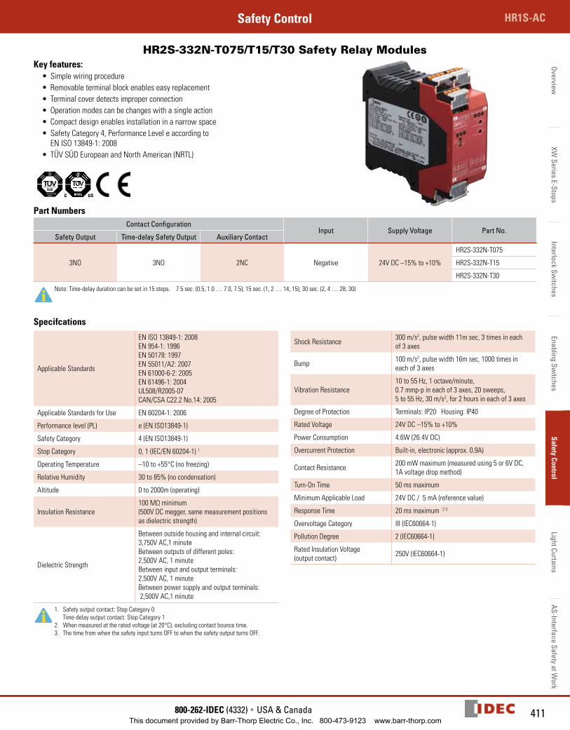
HR2S-332N-T075/T15/T30 Safety Relay Modules Key features:
• Simple wiring procedure• Removable terminal block enables easy replacement• Terminal cover detects improper connection• Operation modes can be changes with a single action• Compact design enables installation in a narrow space• Safety Category 4, Performance Level e according to
EN ISO 13849-1: 2008• TÜV SÜD European and North American (NRTL)
FunctionalSafety
Production
monitoredSafety
tested
Part NumbersContact Configuration
Input Supply Voltage Part No.Safety Output Time-delay Safety Output Auxiliary Contact
3NO 3NO 2NC Negative 24V DC –15% to +10%
HR2S-332N-T075
HR2S-332N-T15
HR2S-332N-T30
Note: Time-delay duration can be set in 15 steps. 7.5 sec. (0.5, 1.0 … 7.0, 7.5); 15 sec. (1, 2 … 14, 15); 30 sec. (2, 4 … 28, 30)
Specifcations
Applicable Standards
EN ISO 13849-1: 2008EN 954-1: 1996EN 50178: 1997EN 55011/A2: 2007EN 61000-6-2: 2005EN 61496-1: 2004UL508/R2005-07 CAN/CSA C22.2 No.14: 2005
Applicable Standards for Use EN 60204-1: 2006
Performance level (PL) e (EN ISO13849-1)
Safety Category 4 (EN ISO13849-1)
Stop Category 0, 1 (IEC/EN 60204-1) 1
Operating Temperature –10 to +55°C (no freezing)
Relative Humidity 30 to 85% (no condensation)
Altitude 0 to 2000m (operating)
Insulation Resistance100 MΩ minimum (500V DC megger, same measurement positions as dielectric strength)
Dielectric Strength
Between outside housing and internal circuit: 3,750V AC,1 minuteBetween outputs of different poles: 2,500V AC, 1 minuteBetween input and output terminals: 2,500V AC, 1 minuteBetween power supply and output terminals: 2,500V AC,1 minute
1. Safety output contact: Stop Category 0 Time-delay output contact: Stop Category 1
2. When measured at the rated voltage (at 20°C), excluding contact bounce time.3. The time from when the safety input turns OFF to when the safety output turns OFF.
Shock Resistance 300 m/s2, pulse width 11m sec, 3 times in each of 3 axes
Bump 100 m/s2, pulse width 16m sec, 1000 times in each of 3 axes
Vibration Resistance10 to 55 Hz, 1 octave/minute, 0.7 mmp-p in each of 3 axes, 20 sweeps,5 to 55 Hz, 30 m/s2, for 2 hours in each of 3 axes
Degree of Protection Terminals: IP20 Housing: IP40
Rated Voltage 24V DC –15% to +10%
Power Consumption 4.6W (26.4V DC)
Overcurrent Protection Built-in, electronic (approx. 0.9A)
Contact Resistance 200 mW maximum (measured using 5 or 6V DC, 1A voltage drop method)
Turn-On Time 50 ms maximum
Minimum Applicable Load 24V DC / 5 mA (reference value)
Response Time 20 ms maximum 2 3
Overvoltage Category III (IEC60664-1)
Pollution Degree 2 (IEC60664-1)
Rated Insulation Voltage (output contact) 250V (IEC60664-1)
This document provided by Barr-Thorp Electric Co., Inc. 800-473-9123 www.barr-thorp.com
Over
view
XW S
erie
s E-
Stop
sIn
terlo
ck S
witc
hes
Enab
ling
Switc
hes
Safe
ty C
ontr
olLi
ght C
urta
ins
AS-In
terfa
ce S
afet
y at
Wor
kSelection Guide Safety Control
412 www.IDEC.com
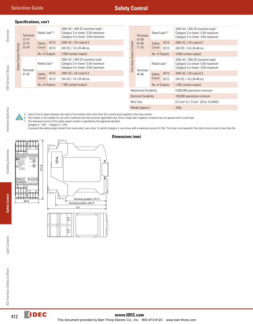
Specifications, con’tOu
tput
Con
tact
Rat
ings
Terminals13-1423-2433-34
Rated Load 5 6250V AC / 30V DC (resistive load) 7
Category 3 or lower: 5.0A maximumCategory 4 or lower: 3.6A maximum
Safety Circuit
AC15 240V AC / 2A cosø=0.3
DC13 24V DC / 1A L/R=48 ms
No. of Outputs 3 (NO contact output)
Terminals41-42
Rated Load 6250V AC / 30V DC (resistive load)Category 3 or lower: 5.0A maximumCategory 4 or lower: 3.6A maximum
Safety Circuit
AC15 240V AC / 2A cosø=0.3
DC13 24V DC / 1A L/R=48 ms
No. of Outputs 1 (NC contact output)
Tim
e-de
lay
Outp
ut C
onta
ct
Terminals57-5867-6877-78
Rated Load 5 6250V AC / 30V DC (resistive load) 7
Category 3 or lower: 5.0A maximumCategory 4 or lower: 3.6A maximum
Safety Circuit
AC15 240V AC / 2A cosø=0.3
DC13 24V DC / 1A L/R=48 ms
No. of Outputs 3 (NO contact output)
Terminals45-46
Rated Load 6250V AC / 30V DC (resistive load)Category 3 or lower: 5.0A maximumCategory 4 or lower: 3.6A maximum
Safety Circuit
AC15 240V AC / 2A cosø=0.3
DC13 24V DC / 1A L/R=48 ms
No. of Outputs 1 (NC contact output)
Mechanical Durability 5,000,000 operations minimum
Electrical Durability 100,000 operations minimum
Wire Size 0.2 mm2 to 1.5 mm2 (24 to 16 AWG)
Weight (approx.) 320g
5. Leave 5 mm of space between the sides of the module when more than 3A is continuously applied to the relay contact.6. The module is not suitable for use with a load less than the minimum applicable load. Once a large load is applied, contacts may not operate with a small load.7. The maximum current of the safety output contact is specified by the approved standard.
Category 4: 3.6A Category 3: 5.0A To prevent the safety output contact from overcurrent, use a fuse. To satisfy Category 4, use a fuse with a maximum current of 3.6A. This fuse is not required if the short circuit current is less than 5A.
Dimensions (mm)
45.0
111
111.
2
13 23 3341Y2S33 A2A1
14 24 3442S11 S12 S21 S22
SAFETYRELAY MODULE
57 67 77 45
58 68 78 46
POW K1 K2
AUTORESET
MANURESET
0.51
4
0.51
4
K1
K2
23
24
33
34
13
14
41
42
K3
K4
67
68
77
78
57
58
45
46
HR2S-332N-T075K3 K4ERR.
max. 7.5sec
max. 7.5sec
SEAL
Terminal position (95.7)Terminal position (76.7)
This document provided by Barr-Thorp Electric Co., Inc. 800-473-9123 www.barr-thorp.com
413800-262-IDEC (4332) • USA & Canada
HR1S-ACSafety ControlOverview
XW Series E-Stops
Interlock Switches
Enabling Switches
Safety ControlLight Curtains
AS-Interface Safety at Work
Terminal Arrangement
1
2
3
4
9
10
8
7
11
5
6
15
14
12
13
13 23 3341Y2S33 A2A1
14 24 3442S11 S12 S21 S22
SAFETYRELAY MODULE
57 67 77 45
58 68 78 46
POW K1 K2
AUTORESET
MANURESET
0.51
4
0.51
4
K1
K2
23
24
33
34
13
14
41
42
K3
K4
67
68
77
78
57
58
45
46
HR2S-332N-T075K3 K4ERR.
max. 7.5sec
max. 7.5sec
13 23 3341Y2S33 A2A1
14 24 3442S11 S12 S21 S22
SAFETYRELAY MODULE
57 67 77 45
58 68 78 46
POW K1 K2
AUTORESET
MANURESET
0.51
4
0.51
4
K1
K2
23
24
33
34
13
14
41
42
K3
K4
67
68
77
78
57
58
45
46
HR2S-332N-T075K3 K4ERR.
max. 7.5sec
max. 7.5sec
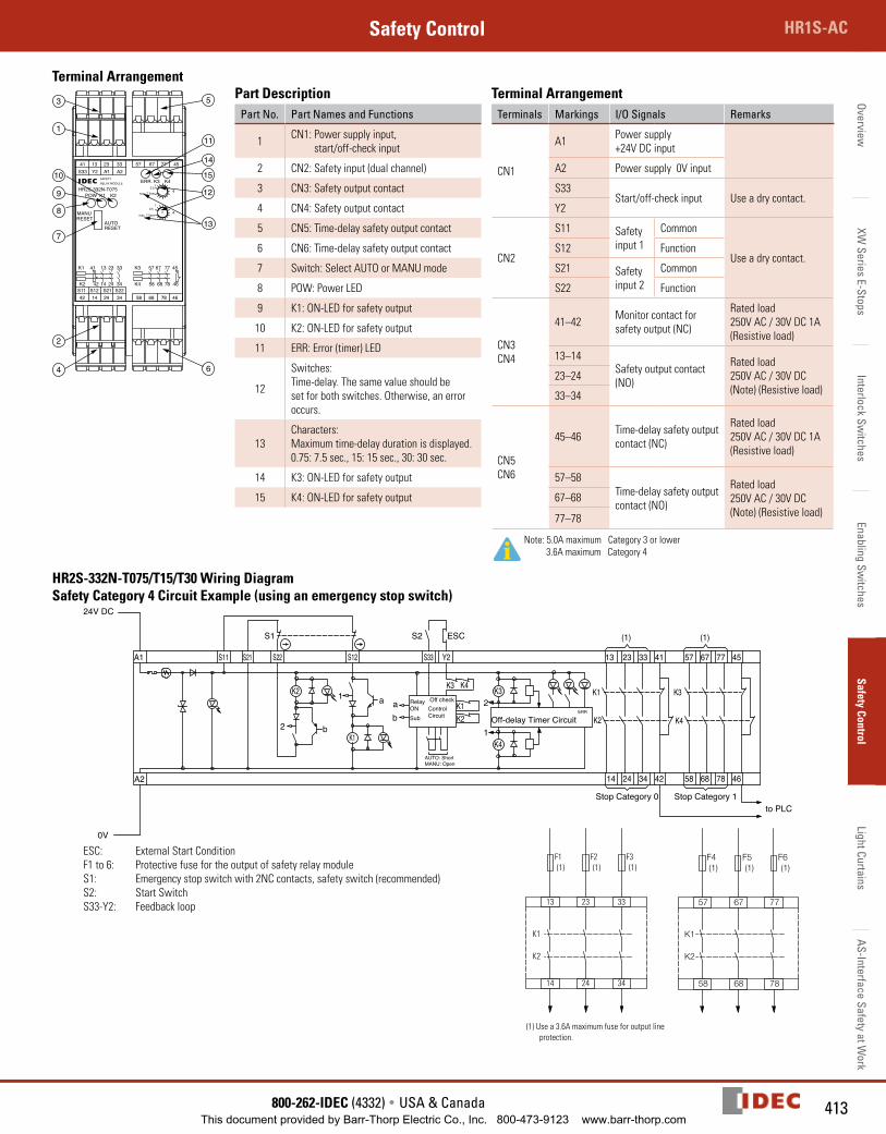
Part DescriptionPart No. Part Names and Functions
1 CN1: Power supply input, start/off-check input
2 CN2: Safety input (dual channel)
3 CN3: Safety output contact
4 CN4: Safety output contact
5 CN5: Time-delay safety output contact
6 CN6: Time-delay safety output contact
7 Switch: Select AUTO or MANU mode
8 POW: Power LED
9 K1: ON-LED for safety output
10 K2: ON-LED for safety output
11 ERR: Error (timer) LED
12
Switches: Time-delay. The same value should be set for both switches. Otherwise, an error occurs.
13Characters: Maximum time-delay duration is displayed. 0.75: 7.5 sec., 15: 15 sec., 30: 30 sec.
14 K3: ON-LED for safety output
15 K4: ON-LED for safety output
Terminal ArrangementTerminals Markings I/O Signals Remarks
CN1
A1 Power supply +24V DC input
A2 Power supply 0V input
S33Start/off-check input Use a dry contact.
Y2
CN2
S11 Safety input 1
Common
Use a dry contact.S12 Function
S21 Safety input 2
Common
S22 Function
CN3CN4
41–42 Monitor contact for safety output (NC)
Rated load250V AC / 30V DC 1A (Resistive load)
13–14Safety output contact (NO)
Rated load250V AC / 30V DC (Note) (Resistive load)
23–24
33–34
CN5CN6
45–46 Time-delay safety output contact (NC)
Rated load250V AC / 30V DC 1A (Resistive load)
57–58Time-delay safety output contact (NO)
Rated load250V AC / 30V DC (Note) (Resistive load)
67–68
77–78
Note: 5.0A maximum Category 3 or lower 3.6A maximum Category 4
HR2S-332N-T075/T15/T30 Wiring DiagramSafety Category 4 Circuit Example (using an emergency stop switch)
K1
K2
13 23 33
14 24 34
F1 F2 F3(1) (1) (1)
(1) Use a 3.6A maximum fuse for output line protection.
ESCS2
ERR
Off-delay Timer Circuit1
2
K4
K3
K2K1
Y2
K4K3
AUTO: ShortMANU: Open
S33
ControlCircuit
Off checkRelayONSubb
aa1
2 b
S12S22
S1
S21S11
0V
24V DC
A2
K2
A1
K1
13
(1) (1)
14 24
23 33
34 42
41
K1
K2 K4
K3
45
4678
7767
6858
57
to PLCStop Category 0 Stop Category 1
ESC: External Start ConditionF1 to 6: Protective fuse for the output of safety relay moduleS1: Emergency stop switch with 2NC contacts, safety switch (recommended) S2: Start SwitchS33-Y2: Feedback loop
This document provided by Barr-Thorp Electric Co., Inc. 800-473-9123 www.barr-thorp.com
Over
view
XW S
erie
s E-
Stop
sIn
terlo
ck S
witc
hes
Enab
ling
Switc
hes
Safe
ty C
ontr
olLi
ght C
urta
ins
AS-In
terfa
ce S
afet
y at
Wor
kSelection Guide Safety Control
414 www.IDEC.com
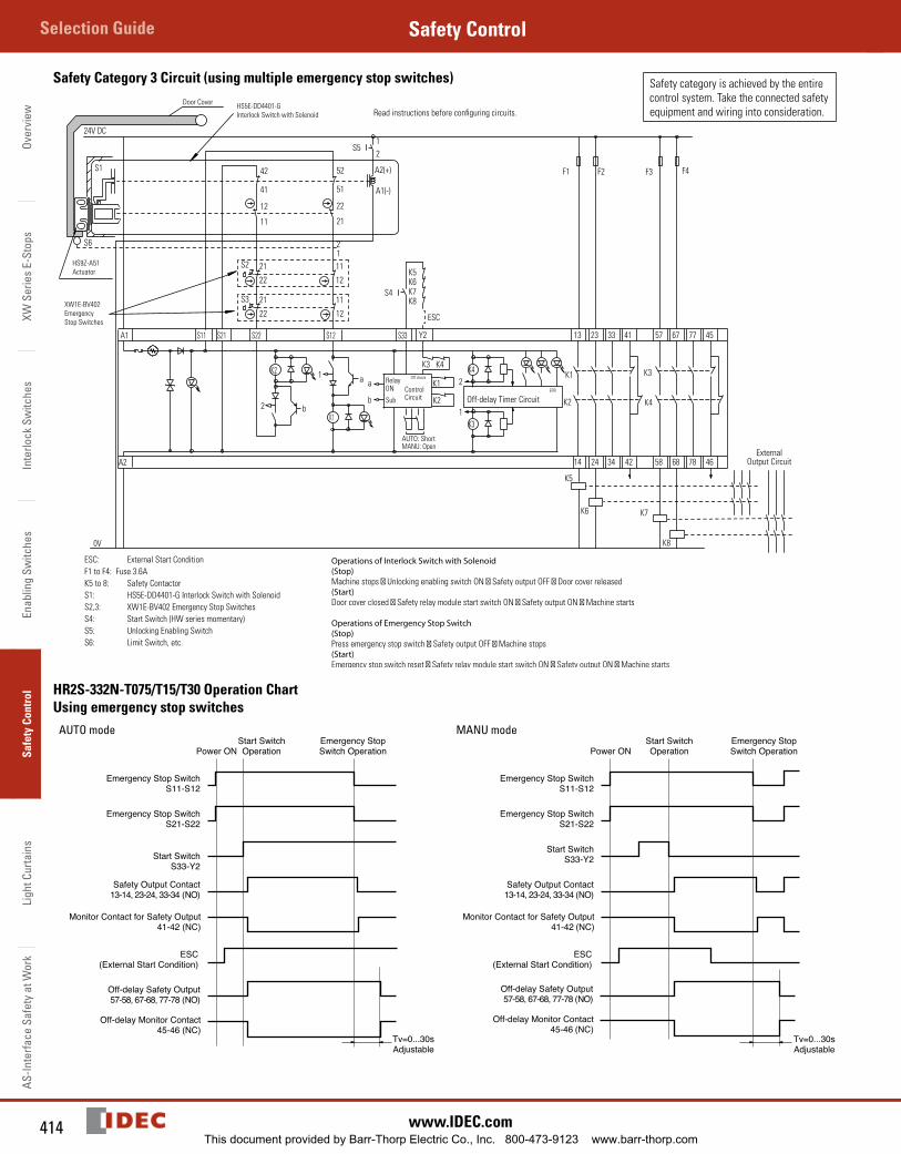
Safety Category 3 Circuit (using multiple emergency stop switches) Safety category is achieved by the entire control system. Take the connected safety equipment and wiring into consideration.
0V
K8K7K6K5
ESC
S4S3 21
22 12
11
11
1222
21S212
57
58 68
67 77
78 46
45
K3
K4K2
K1
41
4234
3323
2414
13
K1
A1
K2
A2
S11 S21 S22 S12
b2
1 a a
b
RelayON
Sub
Off check
ControlCircuit
S33
K3 K4
Y2
K1
K2
K4
K3
2
1Off-delay Timer Circuit
ERR
A1(-)
A2(+)
21
S5
52
51
22
2111
12
41
42
S6
K8
K7K6
K5
S1
24V DC
AUTO: ShortMANU: Open
F1 F2 F3 F4
ESC: External Start ConditionF1 to F4: Fuse 3.6AK5 to 8: Safety ContactorS1: HS5E-DD4401-G Interlock Switch with SolenoidS2,3: XW1E-BV402 Emergency Stop SwitchesS4: Start Switch (HW series momentary)S5: Unlocking Enabling SwitchS6: Limit Switch, etc.
Operations of Interlock Switch with Solenoid(Stop)Machine stops Unlocking enabling switch ON Safety output OFF Door cover released(Start)Door cover closed Safety relay module start switch ON Safety output ON Machine starts
Operations of Emergency Stop Switch(Stop)Press emergency stop switch Safety output OFF Machine stops(Start)Emergency stop switch reset Safety relay module start switch ON Safety output ON Machine starts
HS5E-DD4401-GInterlock Switch with Solenoid
XW1E-BV402EmergencyStop Switches
HS9Z-A51Actuator
Door CoverRead instructions before configuring circuits.
ExternalOutput Circuit
HR2S-332N-T075/T15/T30 Operation ChartUsing emergency stop switches
AUTO mode
Emergency Stop SwitchS11-S12
Emergency Stop SwitchS21-S22
Start SwitchS33-Y2
Safety Output Contact13-14, 23-24, 33-34 (NO)
Off-delay Safety Output57-58, 67-68, 77-78 (NO)
Off-delay Monitor Contact45-46 (NC)
Tv=0...30sAdjustable
Monitor Contact for Safety Output41-42 (NC)
ESC(External Start Condition)
Power ONStart SwitchOperation
Emergency StopSwitch Operation
MANU mode
Off-delay Safety Output57-58, 67-68, 77-78 (NO)
Off-delay Monitor Contact45-46 (NC)
Tv=0...30sAdjustable
Emergency Stop SwitchS11-S12
Emergency Stop SwitchS21-S22
Start SwitchS33-Y2
Safety Output Contact13-14, 23-24, 33-34 (NO)
Monitor Contact for Safety Output41-42 (NC)
ESC(External Start Condition)
Power ONStart SwitchOperation
Emergency StopSwitch Operation
This document provided by Barr-Thorp Electric Co., Inc. 800-473-9123 www.barr-thorp.com
415800-262-IDEC (4332) • USA & Canada
HR1S-ACSafety ControlOverview
XW Series E-Stops
Interlock Switches
Enabling Switches
Safety ControlLight Curtains
AS-Interface Safety at Work
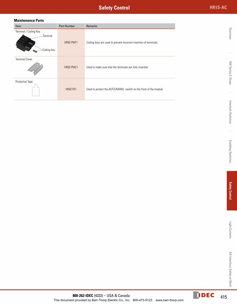
Maintenance PartsItem Part Number Remarks
Terminal / Coding KeyTerminal
Coding key
HR9Z-PMT1 Coding keys are used to prevent incorrect insertion of terminals.
Terminal Cover
HR9Z-PMC1 Used to make sure that the terminals are fully inserted.
Protective Tape
HR9Z-PE1 Used to protect the AUTO/MANU switch on the front of the module.
This document provided by Barr-Thorp Electric Co., Inc. 800-473-9123 www.barr-thorp.com
Over
view
XW S
erie
s E-
Stop
sIn
terlo
ck S
witc
hes
Enab
ling
Switc
hes
Safe
ty C
ontr
olLi
ght C
urta
ins
AS-In
terfa
ce S
afet
y at
Wor
kSelection Guide Safety Control
416 www.IDEC.com
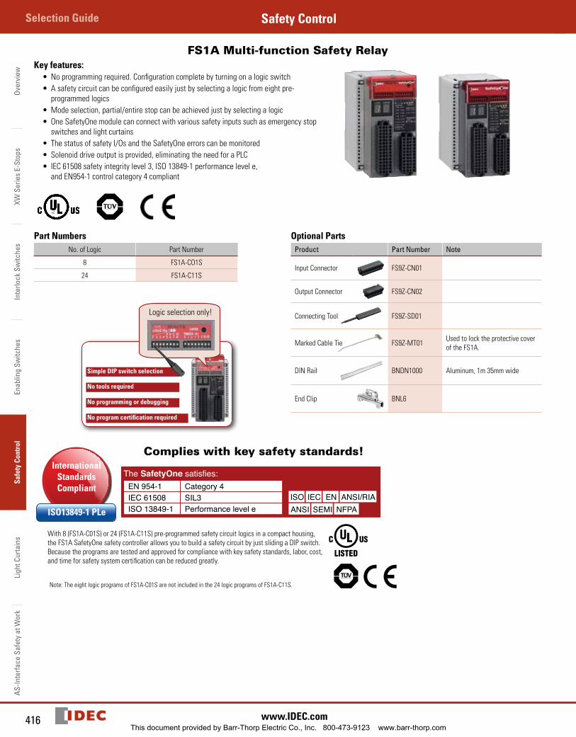
FS1A Multi-function Safety Relay Key features:
• No programming required. Configuration complete by turning on a logic switch• A safety circuit can be configured easily just by selecting a logic from eight pre-
programmed logics• Mode selection, partial/entire stop can be achieved just by selecting a logic• One SafetyOne module can connect with various safety inputs such as emergency stop
switches and light curtains• The status of safety I/Os and the SafetyOne errors can be monitored• Solenoid drive output is provided, eliminating the need for a PLC• IEC 61508 safety integrity level 3, ISO 13849-1 performance level e,
and EN954-1 control category 4 compliant
Part NumbersNo. of Logic Part Number
8 FS1A-CO1S
24 FS1A-C11S
Simple DIP switch selection
No tools required
No programming or debugging
No program certification required
Logic selection only!
Optional PartsProduct Part Number Note
Input Connector FS9Z-CN01
Output Connector FS9Z-CN02
Connecting Tool FS9Z-SD01
Marked Cable Tie FS9Z-MT01 Used to lock the protective cover of the FS1A.
DIN Rail BNDN1000 Aluminum, 1m 35mm wide
End Clip BNL6
Complies with key safety standards!
The SafetyOne satisfies:EN 954-1 Category 4IEC 61508 SIL3ISO 13849-1 Performance level e
ISO IEC EN ANSI/RIAANSI SEMI NFPA
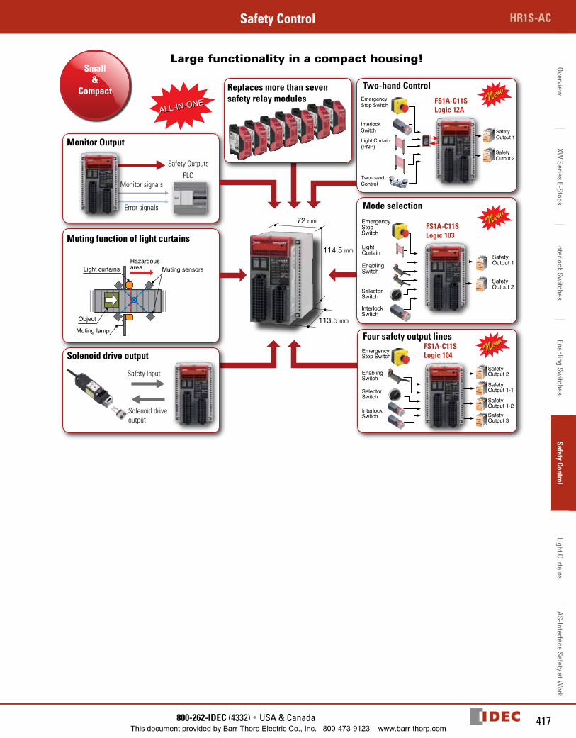
With 8 (FS1A-C01S) or 24 (FS1A-C11S) pre-programmed safety circuit logics in a compact housing, the FS1A SafetyOne safety controller allows you to build a safety circuit by just sliding a DIP switch. Because the programs are tested and approved for compliance with key safety standards, labor, cost, and time for safety system certification can be reduced greatly.
Note: The eight logic programs of FS1A-C01S are not included in the 24 logic programs of FS1A-C11S.
International Standards Compliant
ISO13849-1 PLe
FS1A
This document provided by Barr-Thorp Electric Co., Inc. 800-473-9123 www.barr-thorp.com
417800-262-IDEC (4332) • USA & Canada
HR1S-ACSafety ControlOverview
XW Series E-Stops
Interlock Switches
Enabling Switches
Safety ControlLight Curtains
AS-Interface Safety at Work
Large functionality in a compact housing!Small
&Compact
72 mm
114.5 mm
113.5 mm
Monitor Output
Replaces more than seven safety relay modules
Four safety output lines
Muting function of light curtains
Mode selection
Solenoid drive output
Light curtains
Muting lamp
Muting sensorsHazardousarea
Object
Safety Input
Solenoid drive output
Monitor signals
Error signals
Safety Outputs
EnablingSwitch
LightCurtain
EmergencyStopSwitch
InterlockSwitch
SelectorSwitch
SafetyOutput 1
SafetyOutput 2
EmergencyStop Switch
EnablingSwitch
SelectorSwitch
InterlockSwitch
SafetyOutput 2
SafetyOutput 1-1
SafetyOutput 1-2SafetyOutput 3
Two-handControl
EmergencyStop Switch
Light Curtain(PNP)
InterlockSwitch Safety
Output 1
SafetyOutput 2
ALL-IN-ONEALL-IN-ONE
FS1A-C11SLogic 103
FS1A-C11S Logic 12A
FS1A-C11SLogic 104
PLC
Two-hand Control
This document provided by Barr-Thorp Electric Co., Inc. 800-473-9123 www.barr-thorp.com
Over
view
XW S
erie
s E-
Stop
sIn
terlo
ck S
witc
hes
Enab
ling
Switc
hes
Safe
ty C
ontr
olLi
ght C
urta
ins
AS-In
terfa
ce S
afet
y at
Wor
kSelection Guide Safety Control
418 www.IDEC.com
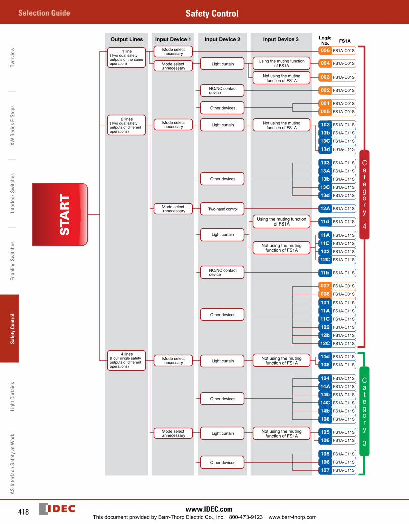
Category 4
Category 3
108 FS1A-C11S
14d FS1A-C11S
11b FS1A-C11S
12C FS1A-C11S
102 FS1A-C11S
11C FS1A-C11S
11A FS1A-C11S
12A FS1A-C11S
13d FS1A-C11S
13C FS1A-C11S
13b FS1A-C11S
13A FS1A-C11S
103 FS1A-C11S
13d FS1A-C11S
13C FS1A-C11S
13b FS1A-C11S
103 FS1A-C11S
11d FS1A-C11S
12C FS1A-C11S
12b FS1A-C11S
102 FS1A-C11S
11C FS1A-C11S
11A FS1A-C11S
101 FS1A-C11S
FS1A-C01S008FS1A-C01S007
FS1A-C01S005FS1A-C01S001
FS1A-C01S002
FS1A-C01S003
FS1A-C01S004
FS1A-C01S006
Output Lines Input Device 1 Input Device 2 Input Device 3 LogicNo. FS1A
Mode selectnecessary
Mode selectnecessary
Mode selectnecessary
Mode selectunnecessary
Mode selectunnecessary
Mode selectunnecessary
Light curtain
Two-hand control
NO/NC contactdevice
NO/NC contactdevice
Other devices
Other devices
Other devices
Other devices
Other devices
Using the muting functionof FS1A
Not using the mutingfunction of FS1A
Using the muting functionof FS1A
Not using the mutingfunction of FS1A
Not using the mutingfunction of FS1A
Not using the mutingfunction of FS1A
Not using the mutingfunction of FS1A
107 FS1A-C11S
106 FS1A-C11S
105 FS1A-C11S
106 FS1A-C11S
105 FS1A-C11S
108 FS1A-C11S
14b FS1A-C11S
14C FS1A-C11S
14b FS1A-C11S
14A FS1A-C11S
104 FS1A-C11S
1 line(Two dual safetyoutputs of the same operation)
2 lines(Two dual safetyoutputs of different operations)
4 lines(Four single safetyoutputs of different operations)
Light curtain
Light curtain
Light curtain
Light curtain
STA
RT
This document provided by Barr-Thorp Electric Co., Inc. 800-473-9123 www.barr-thorp.com
419800-262-IDEC (4332) • USA & Canada
HR1S-ACSafety ControlOverview
XW Series E-Stops
Interlock Switches
Enabling Switches
Safety ControlLight Curtains
AS-Interface Safety at Work
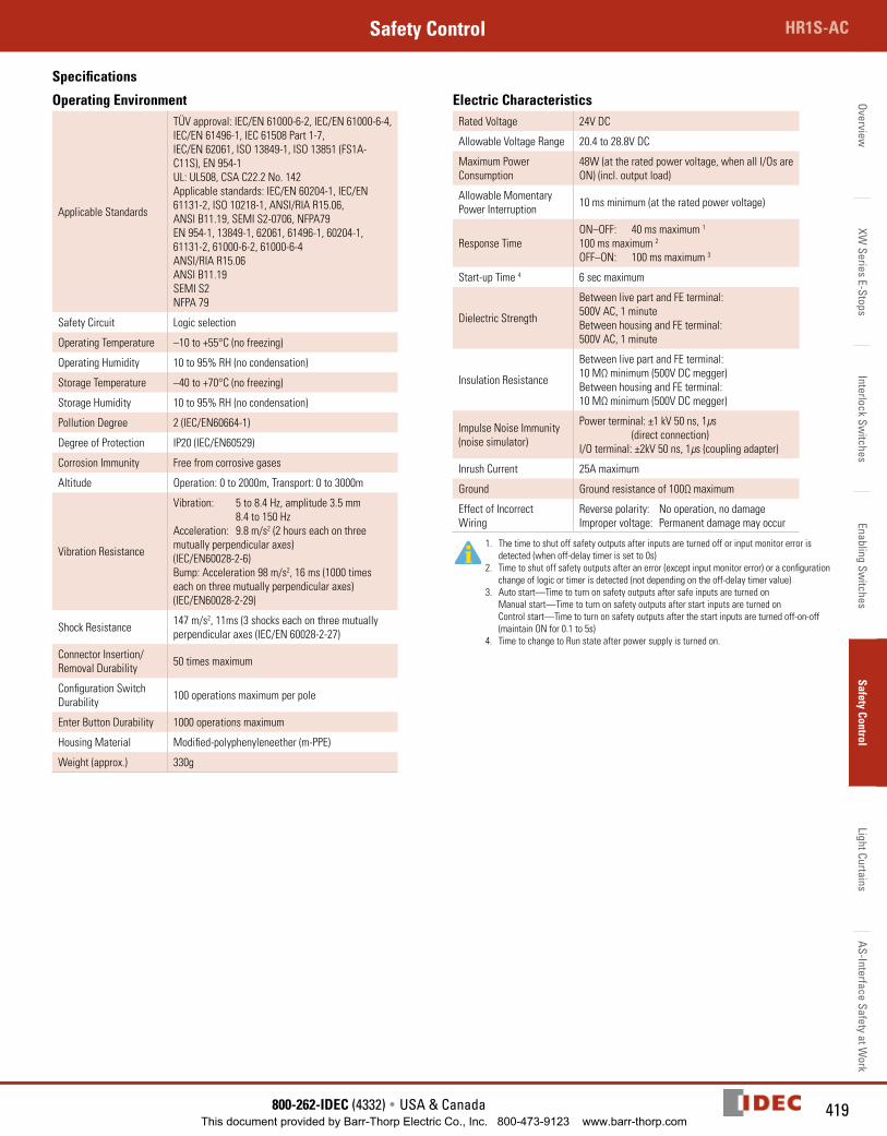
Specifications
Operating Environment
Applicable Standards
TÜV approval: IEC/EN 61000-6-2, IEC/EN 61000-6-4, IEC/EN 61496-1, IEC 61508 Part 1-7, IEC/EN 62061, ISO 13849-1, ISO 13851 (FS1A-C11S), EN 954-1UL: UL508, CSA C22.2 No. 142Applicable standards: IEC/EN 60204-1, IEC/EN 61131-2, ISO 10218-1, ANSI/RIA R15.06, ANSI B11.19, SEMI S2-0706, NFPA79EN 954-1, 13849-1, 62061, 61496-1, 60204-1, 61131-2, 61000-6-2, 61000-6-4ANSI/RIA R15.06ANSI B11.19SEMI S2NFPA 79
Safety Circuit Logic selection
Operating Temperature –10 to +55°C (no freezing)
Operating Humidity 10 to 95% RH (no condensation)
Storage Temperature –40 to +70°C (no freezing)
Storage Humidity 10 to 95% RH (no condensation)
Pollution Degree 2 (IEC/EN60664-1)
Degree of Protection IP20 (IEC/EN60529)
Corrosion Immunity Free from corrosive gases
Altitude Operation: 0 to 2000m, Transport: 0 to 3000m
Vibration Resistance
Vibration: 5 to 8.4 Hz, amplitude 3.5 mm 8.4 to 150 HzAcceleration: 9.8 m/s2 (2 hours each on three mutually perpendicular axes) (IEC/EN60028-2-6)Bump: Acceleration 98 m/s2, 16 ms (1000 times each on three mutually perpendicular axes) (IEC/EN60028-2-29)
Shock Resistance 147 m/s2, 11ms (3 shocks each on three mutually perpendicular axes (IEC/EN 60028-2-27)
Connector Insertion/Removal Durability 50 times maximum
Configuration Switch Durability 100 operations maximum per pole
Enter Button Durability 1000 operations maximum
Housing Material Modified-polyphenyleneether (m-PPE)
Weight (approx.) 330g
Electric CharacteristicsRated Voltage 24V DC
Allowable Voltage Range 20.4 to 28.8V DC
Maximum Power Consumption
48W (at the rated power voltage, when all I/Os are ON) (incl. output load)
Allowable Momentary Power Interruption 10 ms minimum (at the rated power voltage)
Response TimeON–OFF: 40 ms maximum 1 100 ms maximum 2
OFF–ON: 100 ms maximum 3
Start-up Time 4 6 sec maximum
Dielectric Strength
Between live part and FE terminal: 500V AC, 1 minuteBetween housing and FE terminal: 500V AC, 1 minute
Insulation Resistance
Between live part and FE terminal: 10 MΩ minimum (500V DC megger)Between housing and FE terminal: 10 MΩ minimum (500V DC megger)
Impulse Noise Immunity (noise simulator)
Power terminal: ±1 kV 50 ns, 1μs (direct connection)I/O terminal: ±2kV 50 ns, 1μs (coupling adapter)
Inrush Current 25A maximum
Ground Ground resistance of 100Ω maximum
Effect of Incorrect Wiring
Reverse polarity: No operation, no damageImproper voltage: Permanent damage may occur
1. The time to shut off safety outputs after inputs are turned off or input monitor error is detected (when off-delay timer is set to 0s)
2. Time to shut off safety outputs after an error (except input monitor error) or a configuration change of logic or timer is detected (not depending on the off-delay timer value)
3. Auto start—Time to turn on safety outputs after safe inputs are turned on Manual start—Time to turn on safety outputs after start inputs are turned on Control start—Time to turn on safety outputs after the start inputs are turned off-on-off
(maintain ON for 0.1 to 5s)4. Time to change to Run state after power supply is turned on.
This document provided by Barr-Thorp Electric Co., Inc. 800-473-9123 www.barr-thorp.com
Over
view
XW S
erie
s E-
Stop
sIn
terlo
ck S
witc
hes
Enab
ling
Switc
hes
Safe
ty C
ontr
olLi
ght C
urta
ins
AS-In
terfa
ce S
afet
y at
Wor
kSelection Guide Safety Control
420 www.IDEC.com
Examples
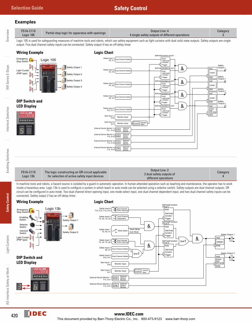
FS1A-C11SLogic 105 Partial stop logic for apparatus with openings Output Line: 4
4 single safety outputs of different operationsCategory
3
Logic 105 is used for safeguarding measures of machine tools and robots, which use safety equipment such as light curtains with dual solid state outputs. Safety outputs are single output. Five dual channel safety inputs can be connected. Safety output 4 has an off-delay timer.
Wiring Example
DIP Switch and LED Display
Logic Chart
SafetyOutput
SafetyOutput
SafetyOutput
SafetyOutput
FS1A-C11SLogic 13b
The logic constructing an OR circuit applicable for selection of active safety input devices
Output Line: 22 dual safety outputs of
different operations
Category4
In machine tools and robots, a hazard source is isolated by a guard in automatic operation. In human-attended operation such as teaching and maintenance, the operator has to work inside a hazardous area. Logic 13b is used to configure a system in which teach or auto mode can be selected using a selector switch. Safety outputs are dual channel outputs. OR circuit can be configured in auto mode. Two dual channel direct opening input, one mode select input, one dual channel dependent input, and two dual channel safety inputs can be connected. Safety output 2 has an off-delay timer.
Wiring Example
DIP Switch and LED Display
Logic Chart
This document provided by Barr-Thorp Electric Co., Inc. 800-473-9123 www.barr-thorp.com
421800-262-IDEC (4332) • USA & Canada
HR1S-ACSafety ControlOverview
XW Series E-Stops
Interlock Switches
Enabling Switches
Safety ControlLight Curtains
AS-Interface Safety at Work
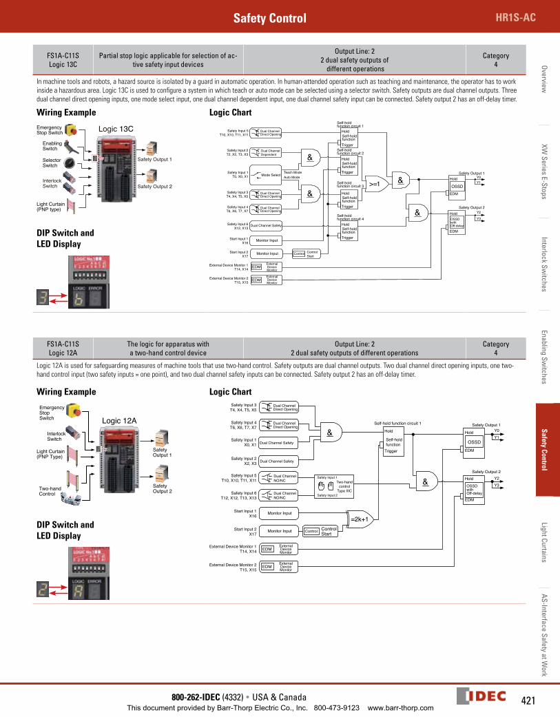
FS1A-C11SLogic 13C
Partial stop logic applicable for selection of ac-tive safety input devices
Output Line: 22 dual safety outputs of
different operations
Category4
In machine tools and robots, a hazard source is isolated by a guard in automatic operation. In human-attended operation such as teaching and maintenance, the operator has to work inside a hazardous area. Logic 13C is used to configure a system in which teach or auto mode can be selected using a selector switch. Safety outputs are dual channel outputs. Three dual channel direct opening inputs, one mode select input, one dual channel dependent input, one dual channel safety input can be connected. Safety output 2 has an off-delay timer.
Wiring Example
DIP Switch and LED Display
Logic Chart
FS1A-C11SLogic 12A
The logic for apparatus with a two-hand control device
Output Line: 22 dual safety outputs of different operations
Category4
Logic 12A is used for safeguarding measures of machine tools that use two-hand control. Safety outputs are dual channel outputs. Two dual channel direct opening inputs, one two-hand control input (two safety inputs = one point), and two dual channel safety inputs can be connected. Safety output 2 has an off-delay timer.
Wiring Example
DIP Switch and LED Display
Logic Chart
This document provided by Barr-Thorp Electric Co., Inc. 800-473-9123 www.barr-thorp.com
Over
view
XW S
erie
s E-
Stop
sIn
terlo
ck S
witc
hes
Enab
ling
Switc
hes
Safe
ty C
ontr
olLi
ght C
urta
ins
AS-In
terfa
ce S
afet
y at
Wor
kSelection Guide Safety Control
422 www.IDEC.com
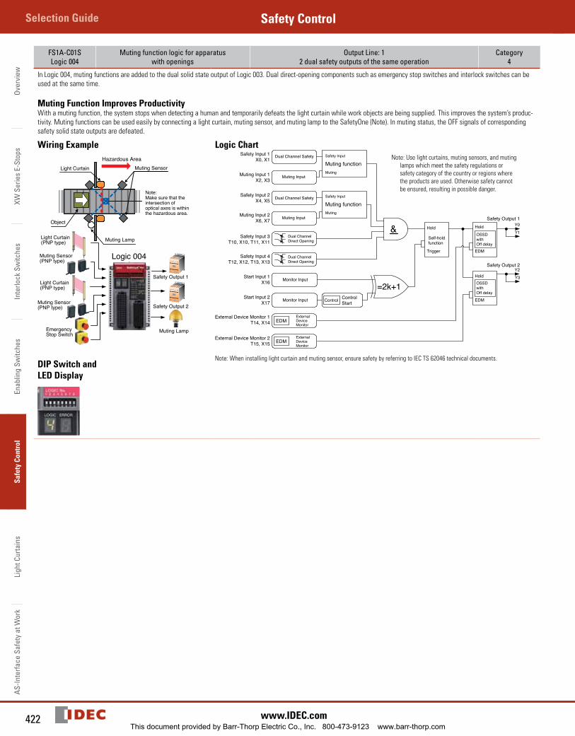
FS1A-C01SLogic 004
Muting function logic for apparatus with openings
Output Line: 12 dual safety outputs of the same operation
Category4
In Logic 004, muting functions are added to the dual solid state output of Logic 003. Dual direct-opening components such as emergency stop switches and interlock switches can be used at the same time.
Muting Function Improves ProductivityWith a muting function, the system stops when detecting a human and temporarily defeats the light curtain while work objects are being supplied. This improves the system’s produc-tivity. Muting functions can be used easily by connecting a light curtain, muting sensor, and muting lamp to the SafetyOne (Note). In muting status, the OFF signals of corresponding safety solid state outputs are defeated.
Wiring Example
DIP Switch and LED Display
Logic Chart
Note: When installing light curtain and muting sensor, ensure safety by referring to IEC TS 62046 technical documents.
Note: Use light curtains, muting sensors, and muting lamps which meet the safety regulations or safety category of the country or regions where the products are used. Otherwise safety cannot be ensured, resulting in possible danger.
This document provided by Barr-Thorp Electric Co., Inc. 800-473-9123 www.barr-thorp.com
423800-262-IDEC (4332) • USA & Canada
HR1S-ACSafety ControlOverview
XW Series E-Stops
Interlock Switches
Enabling Switches
Safety ControlLight Curtains
AS-Interface Safety at Work
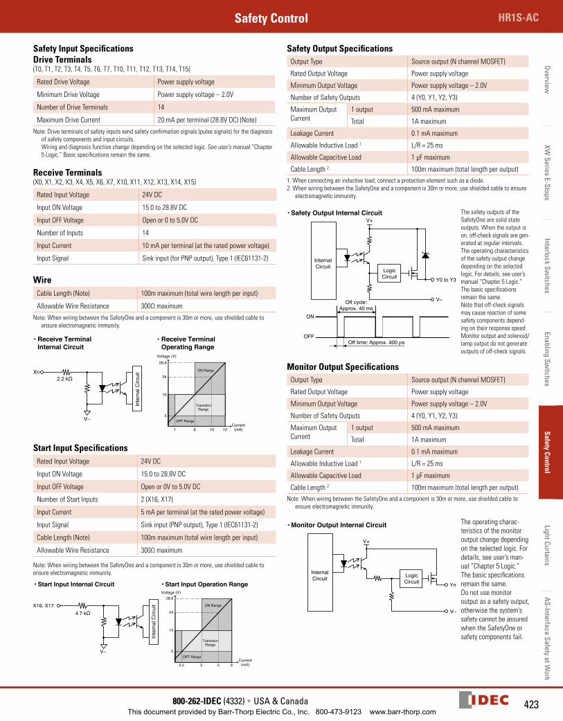
Safety Input SpecificationsDrive Terminals(T0, T1, T2, T3, T4, T5, T6, T7, T10, T11, T12, T13, T14, T15)
Rated Drive Voltage Power supply voltage
Minimum Drive Voltage Power supply voltage – 2.0V
Number of Drive Terminals 14
Maximum Drive Current 20 mA per terminal (28.8V DC) (Note)
Note: Drive terminals of safety inputs send safety confirmation signals (pulse signals) for the diagnosis of safety components and input circuits. Wiring and diagnosis function change depending on the selected logic. See user’s manual “Chapter 5 Logic.” Basic specifications remain the same.
Receive Terminals(X0, X1, X2, X3, X4, X5, X6, X7, X10, X11, X12, X13, X14, X15)
Rated Input Voltage 24V DC
Input ON Voltage 15.0 to 28.8V DC
Input OFF Voltage Open or 0 to 5.0V DC
Number of Inputs 14
Input Current 10 mA per terminal (at the rated power voltage)
Input Signal Sink input (for PNP output), Type 1 (IEC61131-2)
WireCable Length (Note) 100m maximum (total wire length per input)
Allowable Wire Resistance 300Ω maximum
Note: When wiring between the SafetyOne and a component is 30m or more, use shielded cable to ensure electromagnetic immunity.
Start Input SpecificationsRated Input Voltage 24V DC
Input ON Voltage 15.0 to 28.8V DC
Input OFF Voltage Open or 0V to 5.0V DC
Number of Start Inputs 2 (X16, X17)
Input Current 5 mA per terminal (at the rated power voltage)
Input Signal Sink input (PNP output), Type 1 (IEC61131-2)
Cable Length (Note) 100m maximum (total wire length per input)
Allowable Wire Resistance 300Ω maximum
Note: When wiring between the SafetyOne and a component is 30m or more, use shielded cable to ensure electromagnetic immunity.
Safety Output SpecificationsOutput Type Source output (N channel MOSFET)
Rated Output Voltage Power supply voltage
Minimum Output Voltage Power supply voltage – 2.0V
Number of Safety Outputs 4 (Y0, Y1, Y2, Y3)
Maximum Output Current
1 output 500 mA maximum
Total 1A maximum
Leakage Current 0.1 mA maximum
Allowable Inductive Load 1 L/R = 25 ms
Allowable Capacitive Load 1 µF maximum
Cable Length 2 100m maximum (total length per output)1. When connecting an inductive load, connect a protection element such as a diode.2. When wiring between the SafetyOne and a component is 30m or more, use shielded cable to ensure
electromagnetic immunity.
The safety outputs of the SafetyOne are solid state outputs. When the output is on, off-check signals are gen-erated at regular intervals. The operating characteristics of the safety output change depending on the selected logic. For details, see user’s manual “Chapter 5 Logic.” The basic specifications remain the same.Note that off-check signals may cause reaction of some safety components depend-ing on their response speed.Monitor output and solenoid/lamp output do not generate outputs of off-check signals.
Monitor Output SpecificationsOutput Type Source output (N channel MOSFET)
Rated Output Voltage Power supply voltage
Minimum Output Voltage Power supply voltage – 2.0V
Number of Safety Outputs 4 (Y0, Y1, Y2, Y3)
Maximum Output Current
1 output 500 mA maximum
Total 1A maximum
Leakage Current 0.1 mA maximum
Allowable Inductive Load 1 L/R = 25 ms
Allowable Capacitive Load 1 µF maximum
Cable Length 2 100m maximum (total length per output)Note: When wiring between the SafetyOne and a component is 30m or more, use shielded cable to
ensure electromagnetic immunity.
The operating charac-teristics of the monitor output change depending on the selected logic. For details, see user’s man-ual “Chapter 5 Logic.” The basic specifications remain the same.Do not use monitor output as a safety output, otherwise the system’s safety cannot be assured when the SafetyOne or safety components fail.
This document provided by Barr-Thorp Electric Co., Inc. 800-473-9123 www.barr-thorp.com
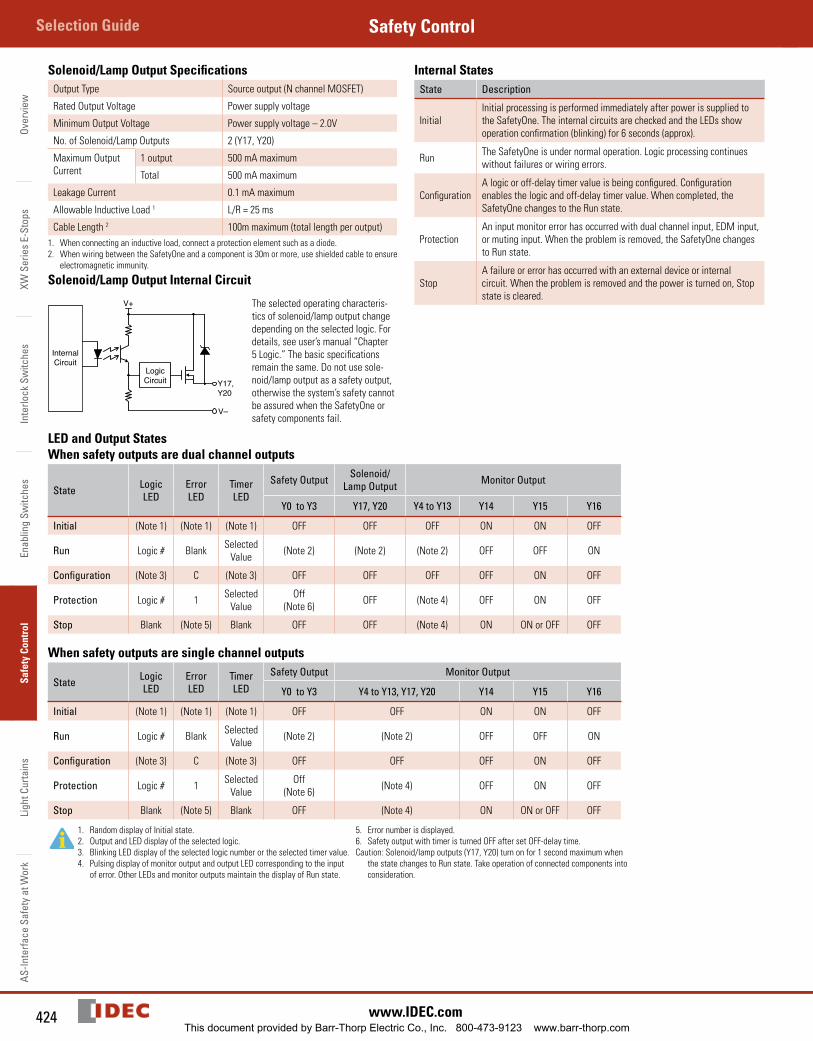
Over
view
XW S
erie
s E-
Stop
sIn
terlo
ck S
witc
hes
Enab
ling
Switc
hes
Safe
ty C
ontr
olLi
ght C
urta
ins
AS-In
terfa
ce S
afet
y at
Wor
kSelection Guide Safety Control
424 www.IDEC.com
Solenoid/Lamp Output SpecificationsOutput Type Source output (N channel MOSFET)
Rated Output Voltage Power supply voltage
Minimum Output Voltage Power supply voltage – 2.0V
No. of Solenoid/Lamp Outputs 2 (Y17, Y20)
Maximum Output Current
1 output 500 mA maximum
Total 500 mA maximum
Leakage Current 0.1 mA maximum
Allowable Inductive Load 1 L/R = 25 ms
Cable Length 2 100m maximum (total length per output)1. When connecting an inductive load, connect a protection element such as a diode.2. When wiring between the SafetyOne and a component is 30m or more, use shielded cable to ensure
electromagnetic immunity.
Solenoid/Lamp Output Internal Circuit
The selected operating characteris-tics of solenoid/lamp output change depending on the selected logic. For details, see user’s manual “Chapter 5 Logic.” The basic specifications remain the same. Do not use sole-noid/lamp output as a safety output, otherwise the system’s safety cannot be assured when the SafetyOne or safety components fail.
Internal StatesState Description
InitialInitial processing is performed immediately after power is supplied to the SafetyOne. The internal circuits are checked and the LEDs show operation confirmation (blinking) for 6 seconds (approx).
Run The SafetyOne is under normal operation. Logic processing continues without failures or wiring errors.
ConfigurationA logic or off-delay timer value is being configured. Configuration enables the logic and off-delay timer value. When completed, the SafetyOne changes to the Run state.
ProtectionAn input monitor error has occurred with dual channel input, EDM input, or muting input. When the problem is removed, the SafetyOne changes to Run state.
StopA failure or error has occurred with an external device or internal circuit. When the problem is removed and the power is turned on, Stop state is cleared.
LED and Output StatesWhen safety outputs are dual channel outputs
State Logic LED
Error LED
Timer LED
Safety Output Solenoid/Lamp Output Monitor Output
Y0 to Y3 Y17, Y20 Y4 to Y13 Y14 Y15 Y16
Initial (Note 1) (Note 1) (Note 1) OFF OFF OFF ON ON OFF
Run Logic # Blank Selected Value (Note 2) (Note 2) (Note 2) OFF OFF ON
Configuration (Note 3) C (Note 3) OFF OFF OFF OFF ON OFF
Protection Logic # 1 Selected Value
Off (Note 6) OFF (Note 4) OFF ON OFF
Stop Blank (Note 5) Blank OFF OFF (Note 4) ON ON or OFF OFF
When safety outputs are single channel outputs
State Logic LED
Error LED
Timer LED
Safety Output Monitor Output
Y0 to Y3 Y4 to Y13, Y17, Y20 Y14 Y15 Y16
Initial (Note 1) (Note 1) (Note 1) OFF OFF ON ON OFF
Run Logic # Blank Selected Value (Note 2) (Note 2) OFF OFF ON
Configuration (Note 3) C (Note 3) OFF OFF OFF ON OFF
Protection Logic # 1 Selected Value
Off (Note 6) (Note 4) OFF ON OFF
Stop Blank (Note 5) Blank OFF (Note 4) ON ON or OFF OFF
1. Random display of Initial state.2. Output and LED display of the selected logic.3. Blinking LED display of the selected logic number or the selected timer value.4. Pulsing display of monitor output and output LED corresponding to the input
of error. Other LEDs and monitor outputs maintain the display of Run state.
5. Error number is displayed.6. Safety output with timer is turned OFF after set OFF-delay time.Caution: Solenoid/lamp outputs (Y17, Y20) turn on for 1 second maximum when
the state changes to Run state. Take operation of connected components into consideration.
This document provided by Barr-Thorp Electric Co., Inc. 800-473-9123 www.barr-thorp.com
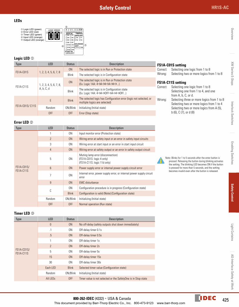
425800-262-IDEC (4332) • USA & Canada
HR1S-ACSafety ControlOverview
XW Series E-Stops
Interlock Switches
Enabling Switches
Safety ControlLight Curtains
AS-Interface Safety at Work
LEDs
0 .1 .5 1 2 5 15 30
SAFE-IN TIMER(S)SAFE-OUT
SOLENOID-OUT
START-IN
X0 X1
X2 X3
X4 X5
X6 X7
X10 X11
X12 X13
X14 X15
X16 X17
Y0 Y1
Y2 Y3
Y17 Y20
LOGIC ERROR
Logic LED jType LED Status Description FS1A-C01S setting
Correct: Selecting one logic from 1 to 8 Wrong: Selecting two or more logics from 1 to 8
FS1A-C11S settingCorrect: Selecting one logic from 1 to 8 Selecting one from 1 to 4, and one from A, b, C, or d. Wrong: Selecting three or more logics from 1 to 8 Selecting two or more logics from 1 to 4 Selecting two or more logics from A (5), b (6), C (7), or d (8)
FS1A-C01S 1, 2, 3, 4, 5, 6, 7, 8ON The selected logic is in Run or Protection state
Blink The selected logic is in Configuration state
FS1A-C11S 1, 2, 3, 4, 5, 6, 7, 8, A, b, C, d
ON The selected logic is in Run or Protection state (Ex. Logic 14A: 4 A 4 A 4 ...)
Blink The selected logic is in Configuration state(Ex. Logic 14A: 4 A OFF A 4 OFF...)
FS1A-C01S/ C11S
E Blink The selected logic has Configuration error (logic not selected, or multiple logics are selected)
Random ON/Blink Initializing (Initial state)
OFF OFF Error (Stop state)
Error LED kType LED Status Description
Note: Blinks for 1 to 5 seconds after the enter button is pressed. Releasing the button during blinking activates the setting. The blinking LED becomes ON if the button is pressed for more than 5 seconds, and the setting becomes invalid even after the button is released.
FS1A-C01S/ FS1A-C11S
1 ON Input monitor error (Protection state)
2 ON Wiring error at safety input or an error in safety input circuits
3 ON Wiring error at start input or an error in start input circuit
4 ON Wiring error at safety output or an error in safety output circuit
5 ONMuting lamp error (disconnection)(FS1A-C01S: logic 4 only)(FS1A-C11S: logic 11d only)
6 ON Power supply error or internal power supply circuit error
7 ON Internal error, power supply error, or internal power supply circuit error
9 ON EMC disturbance
CON Configuration procedure is in progress (Configuration state)
Blink Configuration is valid (Note) (Configuration state)
Random ON/Blink Initializing (Initial state)
OFF OFF Normal operation (Run state)
Timer LED Type LED Status Description
FS1A-CO1S/ FS1A-C11S
0 ON No off-delay (safety outputs shut down immediately)
.1 ON Off-delay timer 0.1s
.5 ON Off-delay timer 0.5s
1 ON Off-delay timer 1s
2 ON Off-delay timer 2s
5 ON Off-delay timer 5s
15 ON Off-delay timer 15s
30 ON Off-delay timer 30s
Each LED Blink Selected timer value (Configuration state)
Random ON/Blink Initializing (Initial state)
All LEDs OFF Timer value is not selected or the SafetyOne is in Stop state
This document provided by Barr-Thorp Electric Co., Inc. 800-473-9123 www.barr-thorp.com
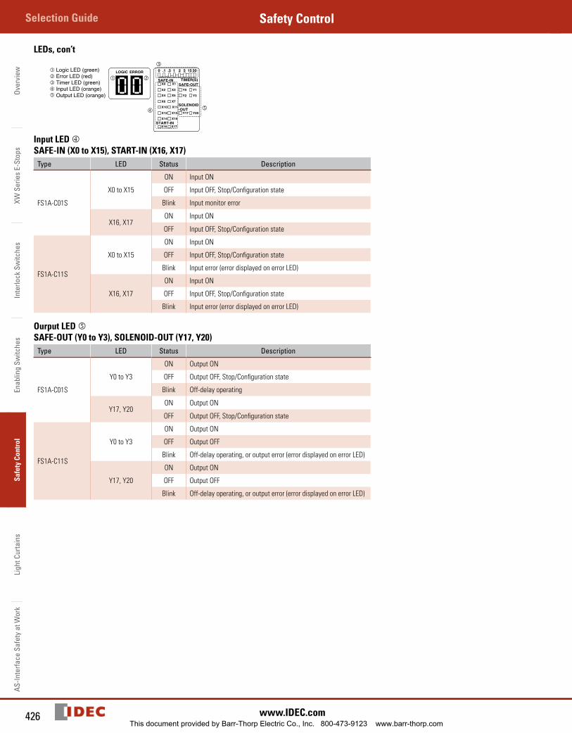
Over
view
XW S
erie
s E-
Stop
sIn
terlo
ck S
witc
hes
Enab
ling
Switc
hes
Safe
ty C
ontr
olLi
ght C
urta
ins
AS-In
terfa
ce S
afet
y at
Wor
kSelection Guide Safety Control
426 www.IDEC.com
LEDs, con’t
0 .1 .5 1 2 5 15 30
SAFE-IN TIMER(S)SAFE-OUT
SOLENOID-OUT
START-IN
X0 X1
X2 X3
X4 X5
X6 X7
X10 X11
X12 X13
X14 X15
X16 X17
Y0 Y1
Y2 Y3
Y17 Y20
LOGIC ERROR
Input LED SAFE-IN (X0 to X15), START-IN (X16, X17)
Type LED Status Description
FS1A-C01S
X0 to X15
ON Input ON
OFF Input OFF, Stop/Configuration state
Blink Input monitor error
X16, X17ON Input ON
OFF Input OFF, Stop/Configuration state
FS1A-C11S
X0 to X15
ON Input ON
OFF Input OFF, Stop/Configuration state
Blink Input error (error displayed on error LED)
X16, X17
ON Input ON
OFF Input OFF, Stop/Configuration state
Blink Input error (error displayed on error LED)
Ourput LED SAFE-OUT (Y0 to Y3), SOLENOID-OUT (Y17, Y20)
Type LED Status Description
FS1A-C01S
Y0 to Y3
ON Output ON
OFF Output OFF, Stop/Configuration state
Blink Off-delay operating
Y17, Y20ON Output ON
OFF Output OFF, Stop/Configuration state
FS1A-C11S
Y0 to Y3
ON Output ON
OFF Output OFF
Blink Off-delay operating, or output error (error displayed on error LED)
Y17, Y20
ON Output ON
OFF Output OFF
Blink Off-delay operating, or output error (error displayed on error LED)
This document provided by Barr-Thorp Electric Co., Inc. 800-473-9123 www.barr-thorp.com
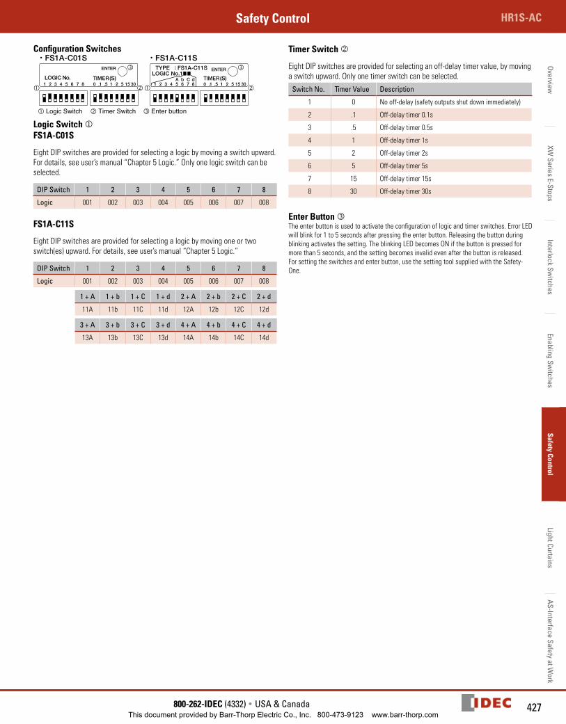
427800-262-IDEC (4332) • USA & Canada
HR1S-ACSafety ControlOverview
XW Series E-Stops
Interlock Switches
Enabling Switches
Safety ControlLight Curtains
AS-Interface Safety at Work
Configuration Switches
TIMER (S)
ENTER
Logic Switch
LOGIC No.1TYPE : FS1A-C11S
LOGIC No. TIMER (S)
ENTER
0 .1 .5 1 2 5 15 301 2 3 4 5 6 7 8 0 .1 .5 1 2 5 15 301 2 3 4 5 6 7 8A b C d
・ FS1A-C01S ・ FS1A-C11S
Timer Switch Enter button
Logic Switch jFS1A-C01S
Eight DIP switches are provided for selecting a logic by moving a switch upward. For details, see user’s manual “Chapter 5 Logic.” Only one logic switch can be selected.
DIP Switch 1 2 3 4 5 6 7 8
Logic 001 002 003 004 005 006 007 008
FS1A-C11S
Eight DIP switches are provided for selecting a logic by moving one or two switch(es) upward. For details, see user’s manual “Chapter 5 Logic.”
DIP Switch 1 2 3 4 5 6 7 8
Logic 001 002 003 004 005 006 007 008
1 + A 1 + b 1 + C 1 + d 2 + A 2 + b 2 + C 2 + d
11A 11b 11C 11d 12A 12b 12C 12d
3 + A 3 + b 3 + C 3 + d 4 + A 4 + b 4 + C 4 + d
13A 13b 13C 13d 14A 14b 14C 14d
Timer Switch k
Eight DIP switches are provided for selecting an off-delay timer value, by moving a switch upward. Only one timer switch can be selected.
Switch No. Timer Value Description
1 0 No off-delay (safety outputs shut down immediately)
2 .1 Off-delay timer 0.1s
3 .5 Off-delay timer 0.5s
4 1 Off-delay timer 1s
5 2 Off-delay timer 2s
6 5 Off-delay timer 5s
7 15 Off-delay timer 15s
8 30 Off-delay timer 30s
Enter Button The enter button is used to activate the configuration of logic and timer switches. Error LED will blink for 1 to 5 seconds after pressing the enter button. Releasing the button during blinking activates the setting. The blinking LED becomes ON if the button is pressed for more than 5 seconds, and the setting becomes invalid even after the button is released. For setting the switches and enter button, use the setting tool supplied with the Safety-One.
This document provided by Barr-Thorp Electric Co., Inc. 800-473-9123 www.barr-thorp.com
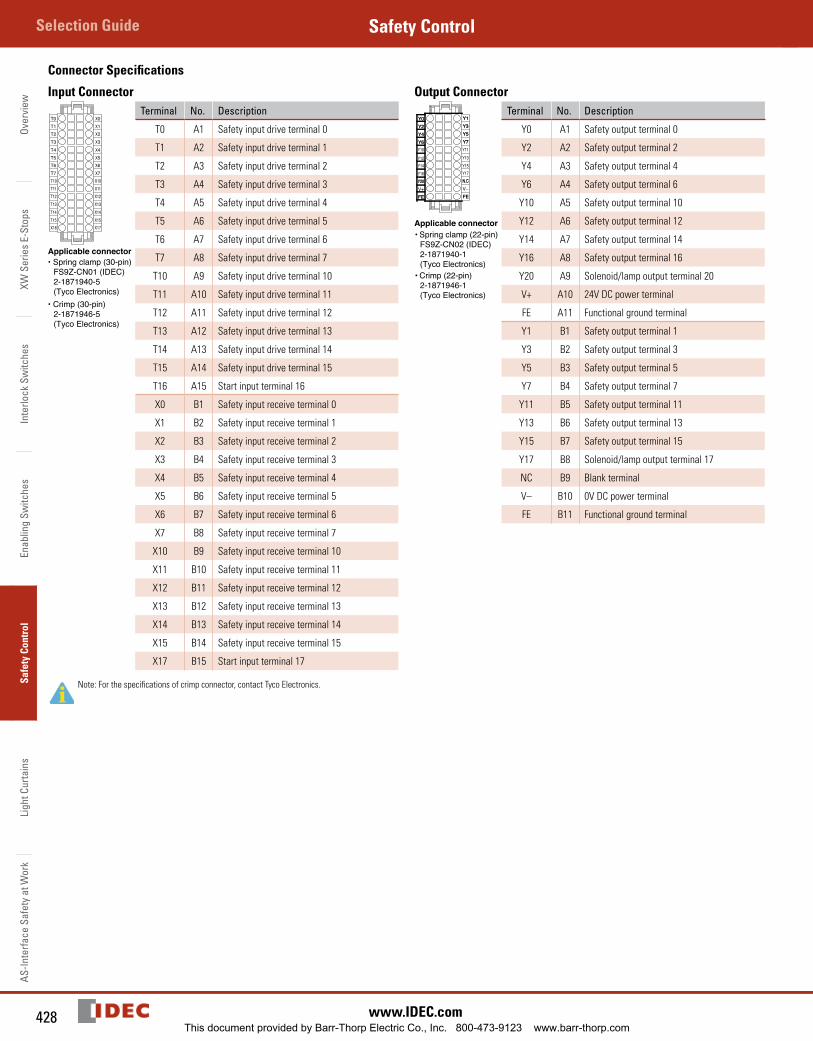
Over
view
XW S
erie
s E-
Stop
sIn
terlo
ck S
witc
hes
Enab
ling
Switc
hes
Safe
ty C
ontr
olLi
ght C
urta
ins
AS-In
terfa
ce S
afet
y at
Wor
kSelection Guide Safety Control
428 www.IDEC.com
Connector Specifications
Input Connector
T0T1T2T3T4T5T6T7T10T11T12T13T14T15X16
X0X1X2X3X4X5X6X7X10X11X12X13X14X15X17
Applicable connector• Spring clamp (30-pin)
FS9Z-CN01 (IDEC)2-1871940-5(Tyco Electronics)
• Crimp (30-pin)2-1871946-5(Tyco Electronics)
Terminal No. Description
T0 A1 Safety input drive terminal 0
T1 A2 Safety input drive terminal 1
T2 A3 Safety input drive terminal 2
T3 A4 Safety input drive terminal 3
T4 A5 Safety input drive terminal 4
T5 A6 Safety input drive terminal 5
T6 A7 Safety input drive terminal 6
T7 A8 Safety input drive terminal 7
T10 A9 Safety input drive terminal 10
T11 A10 Safety input drive terminal 11
T12 A11 Safety input drive terminal 12
T13 A12 Safety input drive terminal 13
T14 A13 Safety input drive terminal 14
T15 A14 Safety input drive terminal 15
T16 A15 Start input terminal 16
X0 B1 Safety input receive terminal 0
X1 B2 Safety input receive terminal 1
X2 B3 Safety input receive terminal 2
X3 B4 Safety input receive terminal 3
X4 B5 Safety input receive terminal 4
X5 B6 Safety input receive terminal 5
X6 B7 Safety input receive terminal 6
X7 B8 Safety input receive terminal 7
X10 B9 Safety input receive terminal 10
X11 B10 Safety input receive terminal 11
X12 B11 Safety input receive terminal 12
X13 B12 Safety input receive terminal 13
X14 B13 Safety input receive terminal 14
X15 B14 Safety input receive terminal 15
X17 B15 Start input terminal 17
Note: For the specifications of crimp connector, contact Tyco Electronics.
Output ConnectorTerminal No. Description
Y0 A1 Safety output terminal 0
Y2 A2 Safety output terminal 2
Y4 A3 Safety output terminal 4
Y6 A4 Safety output terminal 6
Y10 A5 Safety output terminal 10
Y12 A6 Safety output terminal 12
Y14 A7 Safety output terminal 14
Y16 A8 Safety output terminal 16
Y20 A9 Solenoid/lamp output terminal 20
V+ A10 24V DC power terminal
FE A11 Functional ground terminal
Y1 B1 Safety output terminal 1
Y3 B2 Safety output terminal 3
Y5 B3 Safety output terminal 5
Y7 B4 Safety output terminal 7
Y11 B5 Safety output terminal 11
Y13 B6 Safety output terminal 13
Y15 B7 Safety output terminal 15
Y17 B8 Solenoid/lamp output terminal 17
NC B9 Blank terminal
V– B10 0V DC power terminal
FE B11 Functional ground terminal
This document provided by Barr-Thorp Electric Co., Inc. 800-473-9123 www.barr-thorp.com