Embed Size (px)
Citation preview

5
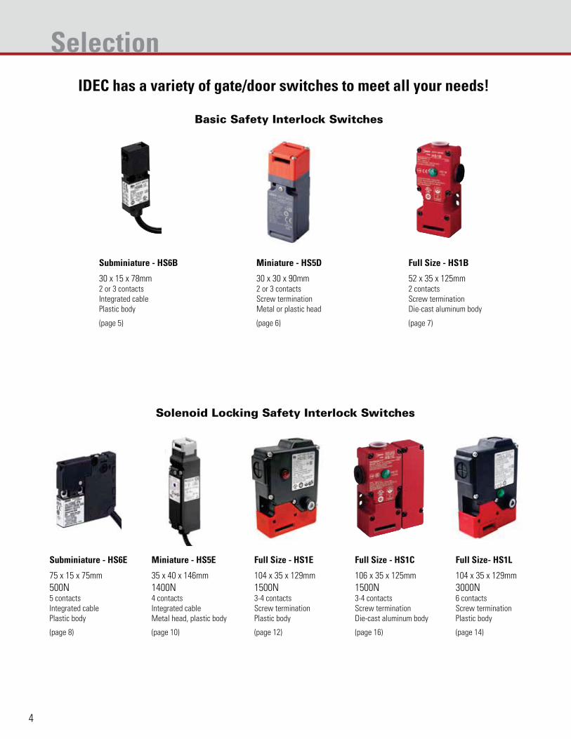
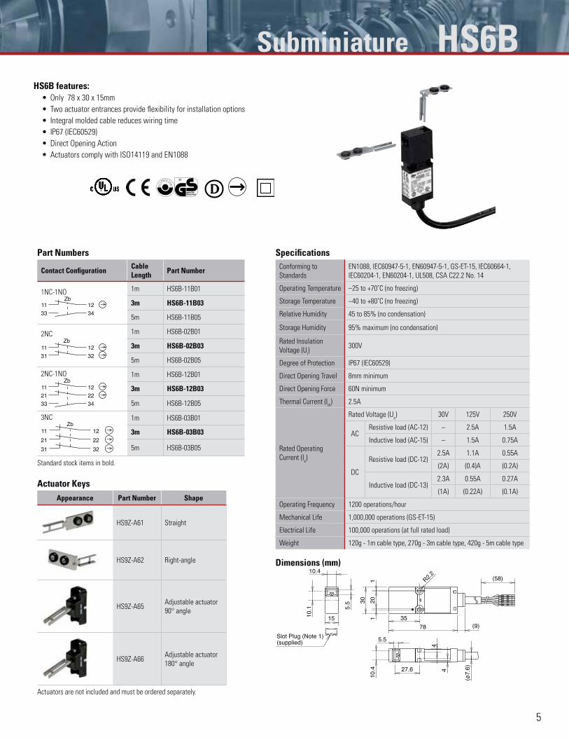
HS6B features:Only 78 x 30 x 15mm
Two actuator entrances provide flexibility for installation options
Integral molded cable reduces wiring time
IP67 (IEC60529)
Direct Opening Action
Actuators comply with ISO14119 and EN1088
Part Numbers
Contact Configuration Cable Length Part Number
1NC-1NO
3433
12Zb
11
1m HS6B-11B01
3m HS6B-11B03
5m HS6B-11B05
2NC
3231
11Zb
12
1m HS6B-02B01
3m HS6B-02B03
5m HS6B-02B05
2NC-1NO
3433
12
22
Zb11
21
1m HS6B-12B01
3m HS6B-12B03
5m HS6B-12B05
3NC
31
21
11Zb
32
22
12
1m HS6B-03B01
3m HS6B-03B03
5m HS6B-03B05
Standard stock items in bold.
SpecificationsConforming to
Standards
EN1088, IEC60947-5-1, EN60947-5-1, GS-ET-15, IEC60664-1,
IEC60204-1, EN60204-1, UL508, CSA C22.2 No. 14
Operating Temperature –25 to +70˚C (no freezing)
Storage Temperature –40 to +80˚C (no freezing)
Relative Humidity 45 to 85% (no condensation)
Storage Humidity 95% maximum (no condensation)
Rated Insulation
Voltage (Ui)
300V
Degree of Protection IP67 (IEC60529)
Direct Opening Travel 8mm minimum
Direct Opening Force 60N minimum
Thermal Current (Ith) 2.5A
Rated Operating
Current (Ie)
Rated Voltage (Ue) 30V 125V 250V
ACResistive load (AC-12) – 2.5A 1.5A
Inductive load (AC-15) – 1.5A 0.75A
DC
Resistive load (DC-12) 2.5A 1.1A 0.55A
(2A) (0.4)A (0.2A)
Inductive load (DC-13)2.3A 0.55A 0.27A
(1A) (0.22A) (0.1A)
Operating Frequency 1200 operations/hour
Mechanical Life 1,000,000 operations (GS-ET-15)
Electrical Life 100,000 operations (at full rated load)
Weight 120g - 1m cable type, 270g - 3m cable type, 420g - 5m cable type
Dimensions (mm)
Slot Plug (Note 1)(supplied)
(58)R2.2
4
4
(ø7.
6)
5.5
10.4 27.6
(9)
11
78
35
2030
10.1 5.
5
10.4
15
Actuator KeysAppearance Part Number Shape
HS9Z-A61 Straight
HS9Z-A62 Right-angle
HS9Z-A65Adjustable actuator
90° angle
HS9Z-A66Adjustable actuator
180° angle
Actuators are not included and must be ordered separately.
Subminiature HS6B
This document provided by Barr-Thorp Electric Co., Inc. 800-473-9123 www.barr-thorp.com
6
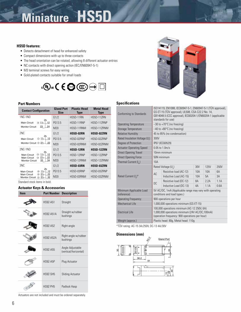
HS5D features:Detects detachment of head for enhanced safety
Compact dimensions with up to three contacts
The head orientation can be rotated, allowing 8 different actuator entries
NC contacts with direct opening action (IEC/EN60947-5-1)
M3 terminal screws for easy wiring
Gold-plated contacts suitable for small loads
Part Numbers
Contact Configuration Gland Port Size
Plastic Head Type
Metal Head Type
1NC-1NO
Main Circuit
Monitor Circuit
1211
23 24
ZbG1/2 HS5D-11RN HS5D-11ZRN
PG13.5 HS5D-11RNP HS5D-11ZRNP
M20 HS5D-11RNM HS5D-11ZRNM
2NC
Main Circuit
Monitor Circuit
11 12
2221
ZbG1/2 HS5D-02RN HS5D-02ZRN
PG13.5 HS5D-02RNP HS5D-02ZRNP
M20 HS5D-02RNM HS5D-02ZRNM
2NC-1NO
121121 2233 34
ZbMain CircuitMain CircuitMonitor Circuit
G1/2 HS5D-12RN HS5D-12ZRN
PG13.5 HS5D-12RNP HS5D-12ZRNP
M20 HS5D-12RNM HS5D-12ZRNM
3NC
11 1221 22
3231
ZbMain CircuitMain CircuitMonitor Circuit
G1/2 HS5D-03RN HS5D-03ZRN
PG13.5 HS5D-03RNP HS5D-03ZRNP
M20 HS5D-03RNM HS5D-03ZRNM
Standard stock items in bold.
Actuator Keys & AccessoriesItem Part Number Description
HS9Z-A51 Straight
HS9Z-A51AStraight w/rubber
bushings
HS9Z-A52 Right-angle
HS9Z-A52ARight-angle w/rubber
bushings
HS9Z-A55Angle Adjustable
(vertical/horizontal)
HS9Z-A5P Plug Actuator
HS9Z-SH5 Sliding Actuator
HS9Z-PH5 Padlock Hasp
Actuators are not included and must be ordered separately.
Specifications
Conforming to Standards
ISO14119, EN1088, IEC60947-5-1, EN60947-5-1 (TÜV approval),
GS-ET-15 (TÜV approval), UL508, CSA C22.2 No. 14,
GB14048.5 (CCC approval), IEC60204-1/EN60204-1 (applicable
standards for use)
Operating Temperature –30 to +70°C (no freezing)
Storage Temperature –40 to +80°C (no freezing)
Relative Humidity 45 to 85% (no condensation)
Rated Insulation Voltage (Ui) 300V
Degree of Protection IP67 (IEC60529)
Actuator Operating Speed 0.05 to 1.0m/s
Direct Opening Travel 10mm minimum
Direct Opening Force 50N minimum
Thermal Current (Ith) 10A
Rated Current (Ie)*
Rated Voltage (Ue) 30V 125V 250V
ACResistive load (AC-12) 10A 10A 6A
Inductive Load (AC-15) 10A 5A 3A
DCResistive load (DC-12) 8A 2.2A 1.1A
Inductive Load (DC-13) 4A 1.1A 0.6A
Minimum Applicable Load
(reference)
5V AC/DC, 1mA (Applicable range may vary with operating
conditions and load types.)
Operating Frequency 900 operations per hour
Mechanical Life 1,000,000 operations minimum (GS-ET-15)
Electrical Life
100,000 operations minimum (AC-12 250V, 6A)
1,000,000 operations minimum (24V AC/DC,100mA)
(operation frequency: 900 operations per hour)
Weight (approx.) Plastic head: 80g, Metal head: 110g
*TÜV rating: AC-15 3A/250V, DC-13 4A/30V
Dimensions (mm)Gland Port
120
1
36.291
R2.
2
15 2430
30
Miniature HS5D
This document provided by Barr-Thorp Electric Co., Inc. 800-473-9123 www.barr-thorp.com
7
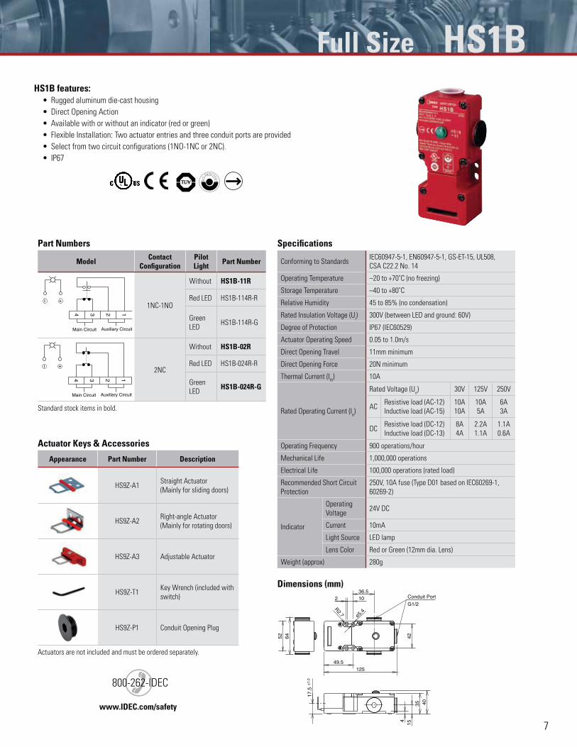
HS1B features:Rugged aluminum die-cast housing
Direct Opening Action
Available with or without an indicator (red or green)
Flexible Installation: Two actuator entries and three conduit ports are provided
Select from two circuit configurations (1NO-1NC or 2NC).
IP67
Part Numbers
Model Contact Configuration
Pilot Light Part Number
2 134
Main Circuit Auxiliary Circuit
- +
1NC-1NO
Without HS1B-11R
Red LED HS1B-114R-R
Green
LEDHS1B-114R-G
2 134
Main Circuit Auxiliary Circuit
- +
2NC
Without HS1B-02R
Red LED HS1B-024R-R
Green
LEDHS1B-024R-G
Standard stock items in bold.
Actuator Keys & Accessories
Appearance Part Number Description
HS9Z-A1Straight Actuator
(Mainly for sliding doors)
HS9Z-A2Right-angle Actuator
(Mainly for rotating doors)
HS9Z-A3 Adjustable Actuator
HS9Z-T1Key Wrench (included with
switch)
HS9Z-P1 Conduit Opening Plug
Actuators are not included and must be ordered separately.
Specifications
Conforming to StandardsIEC60947-5-1, EN60947-5-1, GS-ET-15, UL508,
CSA C22.2 No. 14
Operating Temperature –20 to +70˚C (no freezing)
Storage Temperature –40 to +80˚C
Relative Humidity 45 to 85% (no condensation)
Rated Insulation Voltage (Ui) 300V (between LED and ground: 60V)
Degree of Protection IP67 (IEC60529)
Actuator Operating Speed 0.05 to 1.0m/s
Direct Opening Travel 11mm minimum
Direct Opening Force 20N minimum
Thermal Current (Ith) 10A
Rated Operating Current (Ie)
Rated Voltage (Ue) 30V 125V 250V
ACResistive load (AC-12)
Inductive load (AC-15)
10A
10A
10A
5A
6A
3A
DCResistive load (DC-12)
Inductive load (DC-13)
8A
4A
2.2A
1.1A
1.1A
0.6A
Operating Frequency 900 operations/hour
Mechanical Life 1,000,000 operations
Electrical Life 100,000 operations (rated load)
Recommended Short Circuit
Protection
250V, 10A fuse (Type D01 based on IEC60269-1,
60269-2)
Indicator
Operating
Voltage24V DC
Current 10mA
Light Source LED lamp
Lens Color Red or Green (12mm dia. Lens)
Weight (approx) 280g
Dimensions (mm)
G1/2
Conduit Port
64
15
49.5
42
125
52
ø5.4
2 1036.5
4035
4
±1.0
17.5
R2.7
www.IDEC.com/safety
)800-262-IDEC
Full Size HS1B
This document provided by Barr-Thorp Electric Co., Inc. 800-473-9123 www.barr-thorp.com
8
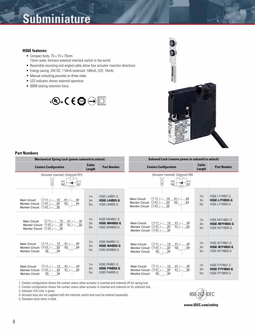
HS6E features:Compact body: 75 × 15 × 75mm
15mm wide, thinnest solenoid interlock switch in the world
Reversible mounting and angled cable allow four actuator insertion directions
Energy saving: 24V DC, 110mA (solenoid: 100mA, LED: 10mA)
Manual unlocking possible on three sides
LED indicator shows solenoid operation
500N locking retention force
Part NumbersMechanical Spring Lock (power solenoid to unlock)
Contact Configuration Cable Length Part Number
(Actuator inserted) (Solenoid OFF)
Monitor Circuit:Monitor Circuit:
41 42121121 22
Main Circuit:
31 3253 54
1m
3m
5m
HS6E-L44B01-G
HS6E-L44B03-GHS6E-L44B05-G
Monitor Circuit:Monitor Circuit:
41 42121121 22
Main Circuit:
31 3251 52
1m
3m
5m
HS6E-M44B01-G
HS6E-M44B03-GHS6E-M44B05-G
Monitor Circuit:Monitor Circuit:
41 42121121 22
Main Circuit:
33 3453 54
1m
3m
5m
HS6E-N44B01-G
HS6E-N44B03-GHS6E-N44B05-G
Monitor Circuit:Monitor Circuit:
41 42121121 22
Main Circuit:
33 3451 52
1m
3m
5m
HS6E-P44B01-G
HS6E-P44B03-GHS6E-P44B05-G
1. Contact configuration shows the contact status when actuator is inserted and solenoid off for spring lock.
2. Contact configuration shows the contact status when actuator is inserted and solenoid on for solenoid lock.
3. Indicator LED color is green.
4. Actuator keys are not supplied with the interlock switch and must be ordered separately.
5. Standard stock items in bold.
Solenoid Lock (remove power to solenoid to unlock)
Contact Configuration Cable Length Part Number
(Actuator inserted) (Solenoid ON)
Monitor Circuit:Monitor Circuit:
41 42121121 22
Main Circuit:
31 3253 54
1m
3m
5m
HS6E-L7Y4B01-G
HS6E-L7Y4B03-GHS6E-L7Y4B05-G
Monitor Circuit:Monitor Circuit:
41 42121121 22
Main Circuit:
31 3251 52
1m
3m
5m
HS6E-M7Y4B01-G
HS6E-M7Y4B03-GHS6E-M7Y4B05-G
Monitor Circuit:Monitor Circuit:
41 42121121 22
Main Circuit:
33 3453 54
1m
3m
5m
HS6E-N7Y4B01-G
HS6E-N7Y4B03-GHS6E-N7Y4B05-G
Monitor Circuit:Monitor Circuit:
41 42121121 22
Main Circuit:
33 3451 52
1m
3m
5m
HS6E-P7Y4B01-G
HS6E-P7Y4B03-GHS6E-P7Y4B05-G
A1A2(+) (–)
A1A2(+) (–)
Subminiature
www.IDEC.com/safety
)800-262-IDEC
This document provided by Barr-Thorp Electric Co., Inc. 800-473-9123 www.barr-thorp.com
9
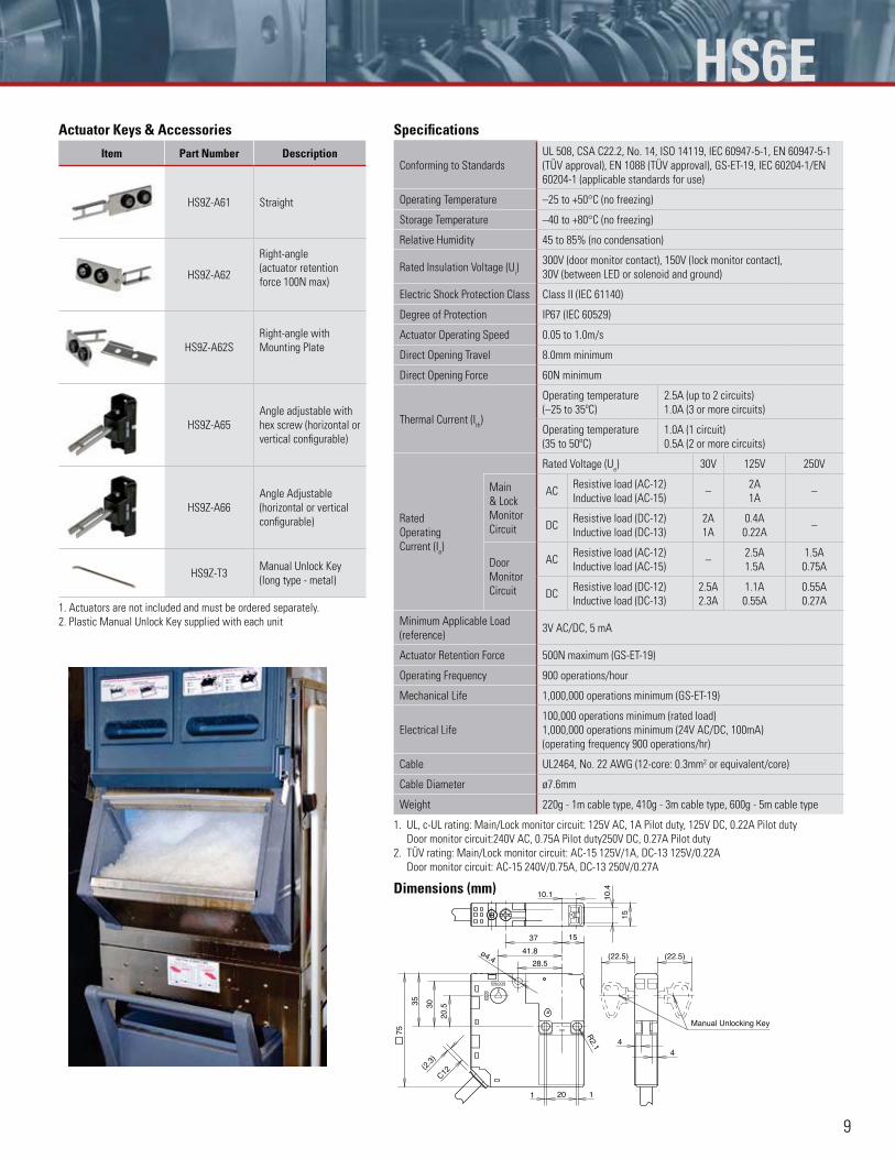
HS6EActuator Keys & Accessories
Item Part Number Description
HS9Z-A61 Straight
HS9Z-A62
Right-angle
(actuator retention
force 100N max)
HS9Z-A62S
Right-angle with
Mounting Plate
HS9Z-A65
Angle adjustable with
hex screw (horizontal or
vertical configurable)
HS9Z-A66
Angle Adjustable
(horizontal or vertical
configurable)
HS9Z-T3Manual Unlock Key
(long type - metal)
1. Actuators are not included and must be ordered separately.
2. Plastic Manual Unlock Key supplied with each unit
Specifications
Conforming to Standards
UL 508, CSA C22.2, No. 14, ISO 14119, IEC 60947-5-1, EN 60947-5-1
(TÜV approval), EN 1088 (TÜV approval), GS-ET-19, IEC 60204-1/EN
60204-1 (applicable standards for use)
Operating Temperature –25 to +50°C (no freezing)
Storage Temperature –40 to +80°C (no freezing)
Relative Humidity 45 to 85% (no condensation)
Rated Insulation Voltage (Ui)
300V (door monitor contact), 150V (lock monitor contact),
30V (between LED or solenoid and ground)
Electric Shock Protection Class Class II (IEC 61140)
Degree of Protection IP67 (IEC 60529)
Actuator Operating Speed 0.05 to 1.0m/s
Direct Opening Travel 8.0mm minimum
Direct Opening Force 60N minimum
Thermal Current (Ith)
Operating temperature
(–25 to 35ºC)
2.5A (up to 2 circuits)
1.0A (3 or more circuits)
Operating temperature
(35 to 50ºC)
1.0A (1 circuit)
0.5A (2 or more circuits)
Rated
Operating
Current (Ie)
Rated Voltage (Ue) 30V 125V 250V
Main
& Lock
Monitor
Circuit
ACResistive load (AC-12)
Inductive load (AC-15)–
2A
1A–
DCResistive load (DC-12)
Inductive load (DC-13)
2A
1A
0.4A
0.22A–
Door
Monitor
Circuit
ACResistive load (AC-12)
Inductive load (AC-15)–
2.5A
1.5A
1.5A
0.75A
DCResistive load (DC-12)
Inductive load (DC-13)
2.5A
2.3A
1.1A
0.55A
0.55A
0.27A
Minimum Applicable Load
(reference)3V AC/DC, 5 mA
Actuator Retention Force 500N maximum (GS-ET-19)
Operating Frequency 900 operations/hour
Mechanical Life 1,000,000 operations minimum (GS-ET-19)
Electrical Life
100,000 operations minimum (rated load)
1,000,000 operations minimum (24V AC/DC, 100mA)
(operating frequency 900 operations/hr)
Cable UL2464, No. 22 AWG (12-core: 0.3mm2 or equivalent/core)
Cable Diameter ø7.6mm
Weight 220g - 1m cable type, 410g - 3m cable type, 600g - 5m cable type
1. UL, c-UL rating: Main/Lock monitor circuit: 125V AC, 1A Pilot duty, 125V DC, 0.22A Pilot duty
Door monitor circuit:240V AC, 0.75A Pilot duty250V DC, 0.27A Pilot duty
2. TÜV rating: Main/Lock monitor circuit: AC-15 125V/1A, DC-13 125V/0.22A
Door monitor circuit: AC-15 240V/0.75A, DC-13 250V/0.27A
Dimensions (mm)
Manual Unlocking Key
11 20
(2.3
)
C12
35 30
20.5
10.1
15
10.4
15
44
75 R2.1
28.5
37
41.8ø4.4 (22.5) (22.5)
This document provided by Barr-Thorp Electric Co., Inc. 800-473-9123 www.barr-thorp.com
10
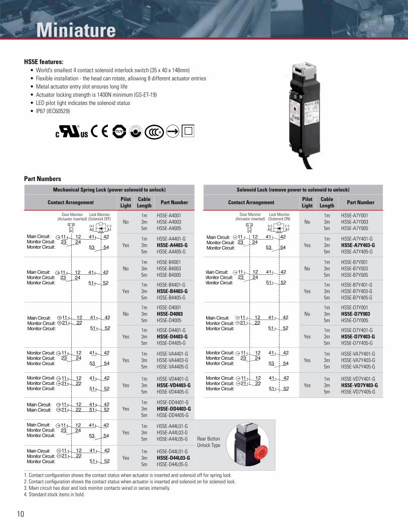
HS5E features:World’s smallest 4 contact solenoid interlock switch (35 x 40 x 146mm)
Flexible installation - the head can rotate, allowing 8 different actuator entries
Metal actuator entry slot ensures long life
Actuator locking strength is 1400N minimum (GS-ET-19)
LED pilot light indicates the solenoid status
IP67 (IEC60529)
Part Numbers
Mechanical Spring Lock (power solenoid to unlock) Solenoid Lock (remove power to solenoid to unlock)
Contact Arrangement Pilot Light
Cable Length Part Number Contact Arrangement Pilot
LightCable Length Part Number
241123
12 4241
5453
Main Circuit:Monitor Circuit:Monitor Circuit:
No
1m
3m
5m
HS5E-A4001
HS5E-A4003
HS5E-A4005
Main Circuit:24
1123
12 4241
5453Monitor Circuit:Monitor Circuit:
No
1m
3m
5m
HS5E-A7Y001
HS5E-A7Y003
HS5E-A7Y005
Yes
1m
3m
5m
HS5E-A4401-G
HS5E-A4403-GHS5E-A4405-G
Yes
1m
3m
5m
HS5E-A7Y401-G
HS5E-A7Y403-GHS5E-A7Y405-G
51 52
41 42122311
24Main Circuit:Monitor Circuit:Monitor Circuit:
No
1m
3m
5m
HS5E-B4001
HS5E-B4003
HS5E-B4005
51 52
41 42122311
24Main Circuit:Monitor Circuit:Monitor Circuit:
No
1m
3m
5m
HS5E-B7Y001
HS5E-B7Y003
HS5E-B7Y005
Yes
1m
3m
5m
HS5E-B4401-G
HS5E-B4403-GHS5E-B4405-G
Yes
1m
3m
5m
HS5E-B7Y401-G
HS5E-B7Y403-G
HS5E-B7Y405-G
Monitor Circuit:Monitor Circuit:
Main Circuit: 41121121 22
51 52
42No
1m
3m
5m
HS5E-D4001
HS5E-D4003HS5E-D4005
Monitor Circuit:Monitor Circuit:
41121121 22
51
Main Circuit:
52
42No
1m
3m
5m
HS5E-D7Y001
HS5E-D7Y003HS5E-D7Y005
Yes
1m
3m
5m
HS5E-D4401-G
HS5E-D4403-GHS5E-D4405-G
Yes
1m
3m
5m
HS5E-D7Y401-G
HS5E-D7Y403-GHS5E-D7Y405-G
241123
12 4241
5453
Monitor Circuit:Monitor Circuit:Monitor Circuit:
Yes
1m
3m
5m
HS5E-VA4401-G
HS5E-VA4403-G
HS5E-VA4405-G
241123
12 4241
5453
Monitor Circuit:Monitor Circuit:Monitor Circuit:
Yes
1m
3m
5m
HS5E-VA7Y401-G
HS5E-VA7Y403-G
HS5E-VA7Y405-G
41121121 22
51 52
42Monitor Circuit:Monitor Circuit:Monitor Circuit:
Yes
1m
3m
5m
HS5E-VD4401-G
HS5E-VD4403-GHS5E-VD4405-G
41121121 22
51 52
42Monitor Circuit:Monitor Circuit:Monitor Circuit:
Yes
1m
3m
5m
HS5E-VD7Y401-G
HS5E-VD7Y403-GHS5E-VD7Y405-G
51 5241 4212
2111
22Main Circuit:Main Circuit: Yes
1m
3m
5m
HS5E-DD4401-G
HS5E-DD4403-GHS5E-DD4405-G
241123
12 4241
5453
Main Circuit:Monitor Circuit:Monitor Circuit: Yes
1m
3m
5m
HS5E-A44L01-G
HS5E-A44L03-G
HS5E-A44L05-G Rear Button
Unlock Type
Monitor Circuit:Monitor Circuit:
Main Circuit: 41121121 22
51 52
42
Yes
1m
3m
5m
HS5E-D44L01-G
HS5E-D44L03-GHS5E-D44L05-G
1. Contact configuration shows the contact status when actuator is inserted and solenoid off for spring lock.
2. Contact configuration shows the contact status when actuator is inserted and solenoid on for solenoid lock.
3. Main circuit has door and lock monitor contacts wired in series internally.
4. Standard stock items in bold.
A1A2(+) (–)
Door Monitor (Actuator inserted)
Lock Monitor (Solenoid ON)
A1A2(+) (–)
Door Monitor (Actuator inserted)
Lock Monitor (Solenoid OFF)
Miniature
This document provided by Barr-Thorp Electric Co., Inc. 800-473-9123 www.barr-thorp.com
11
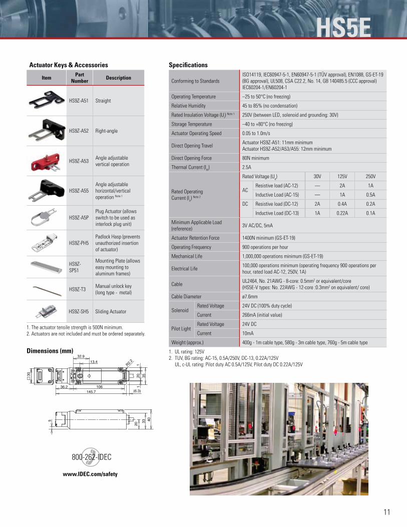
HS5EActuator Keys & Accessories
Item Part Number Description
HS9Z-A51 Straight
HS9Z-A52 Right-angle
HS9Z-A53Angle adjustable
vertical operation
HS9Z-A55
Angle adjustable
horizontal/vertical
operation Note 1
HS9Z-A5P
Plug Actuator (allows
switch to be used as
interlock plug unit)
HS9Z-PH5
Padlock Hasp (prevents
unauthorized insertion
of actuator)
HS9Z-
SP51
Mounting Plate (allows
easy mounting to
aluminum frames)
HS9Z-T3Manual unlock key
(long type - metal)
HS9Z-SH5 Sliding Actuator
1. The actuator tensile strength is 500N minimum.
2. Actuators are not included and must be ordered separately.
Dimensions (mm)
335
30
13.4
32.9
20
40
36.2 106145.7 (6.3)
20 35
11
R2.2
Specifications
Conforming to Standards
ISO14119, IEC60947-5-1, EN60947-5-1 (TÜV approval), EN1088, GS-ET-19
(BG approval), UL508, CSA C22.2, No. 14, GB 140485.5 (CCC approval)
IEC60204-1/EN60204-1
Operating Temperature –25 to 50°C (no freezing)
Relative Humidity 45 to 85% (no condensation)
Rated Insulation Voltage (Ui) Note 1 250V (between LED, solenoid and grounding: 30V)
Storage Temperature –40 to +80°C (no freezing)
Actuator Operating Speed 0.05 to 1.0m/s
Direct Opening TravelActuator HS9Z-A51: 11mm minimum
Actuator HS9Z-A52/A53/A55: 12mm minimum
Direct Opening Force 80N minimum
Thermal Current (Ith) 2.5A
Rated Operating
Current (Ie) Note 2
Rated Voltage (Ue) 30V 125V 250V
ACResistive load (AC-12) — 2A 1A
Inductive Load (AC-15) — 1A 0.5A
DC Resistive load (DC-12) 2A 0.4A 0.2A
Inductive Load (DC-13) 1A 0.22A 0.1A
Minimum Applicable Load
(reference)3V AC/DC, 5mA
Actuator Retention Force 1400N minimum (GS-ET-19)
Operating Frequency 900 operations per hour
Mechanical Life 1,000,000 operations minimum (GS-ET-19)
Electrical Life100,000 operations minimum (operating frequency 900 operations per
hour, rated load AC-12, 250V, 1A)
CableUL2464, No. 21AWG - 8-core: 0.5mm2 or equivalent/core
(HS5E-V types: No. 22AWG - 12-core :0.3mm2 on equivalent/ core)
Cable Diameter ø7.6mm
SolenoidRated Voltage 24V DC (100% duty cycle)
Current 266mA (initial value)
Pilot LightRated Voltage 24V DC
Current 10mA
Weight (approx.) 400g - 1m cable type, 580g - 3m cable type, 760g - 5m cable type
1. UL rating: 125V
2. TUV, BG rating: AC-15, 0.5A/250V, DC-13, 0.22A/125V
UL, c-UL rating: Pilot duty AC 0.5A/125V, Pilot duty DC 0.22A/125V
www.IDEC.com/safety
)800-262-IDEC
This document provided by Barr-Thorp Electric Co., Inc. 800-473-9123 www.barr-thorp.com
12
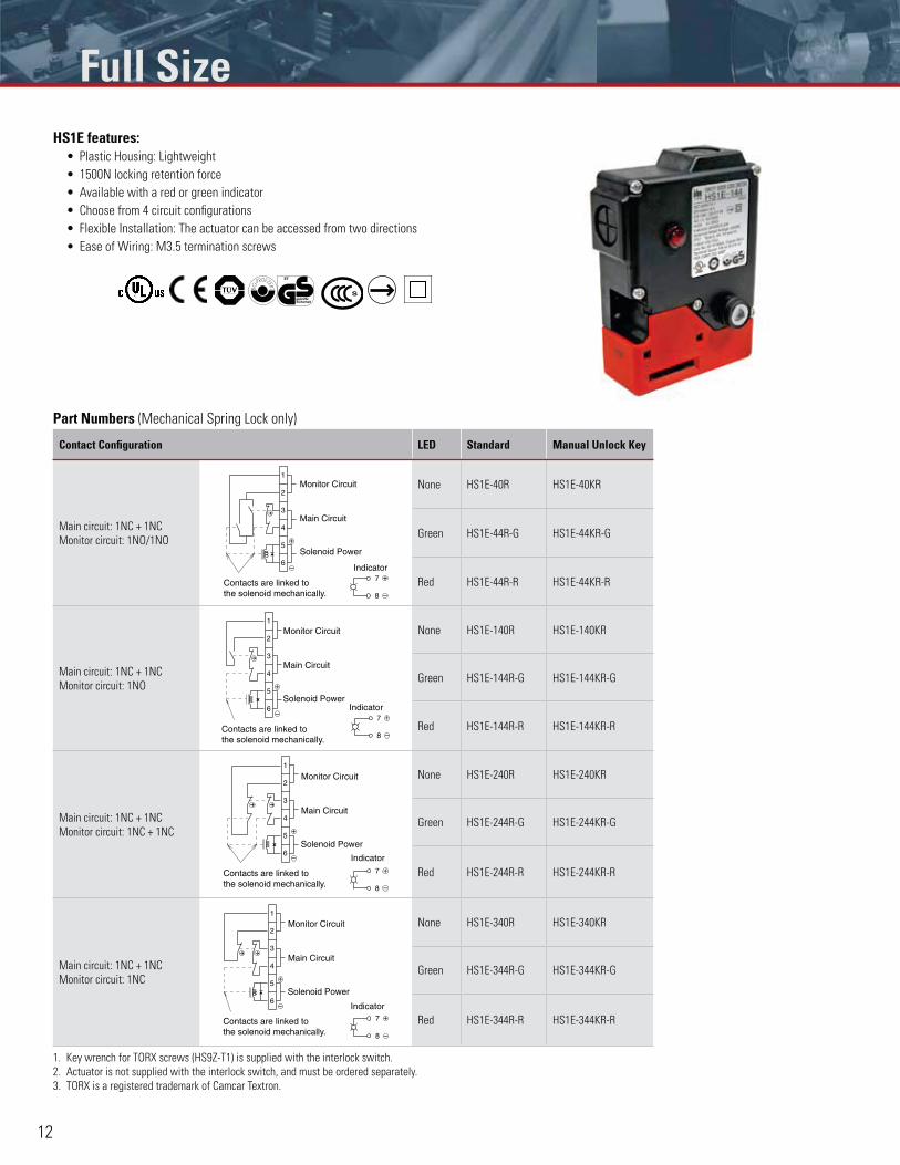
HS1E features:Plastic Housing: Lightweight
1500N locking retention force
Available with a red or green indicator
Choose from 4 circuit configurations
Flexible Installation: The actuator can be accessed from two directions
Ease of Wiring: M3.5 termination screws
Part Numbers (Mechanical Spring Lock only)
Contact Configuration LED Standard Manual Unlock Key
Main circuit: 1NC + 1NC
Monitor circuit: 1NO/1NO
7
8
6
2
1
3
4
5
Contacts are linked to the solenoid mechanically.
Indicator
Monitor Circuit
Main Circuit
Solenoid Power
None HS1E-40R HS1E-40KR
Green HS1E-44R-G HS1E-44KR-G
Red HS1E-44R-R HS1E-44KR-R
Main circuit: 1NC + 1NC
Monitor circuit: 1NO
7
8
6
2
1
3
4
5
Monitor Circuit
Main Circuit
Solenoid Power
Contacts are linked to the solenoid mechanically.
Indicator
None HS1E-140R HS1E-140KR
Green HS1E-144R-G HS1E-144KR-G
Red HS1E-144R-R HS1E-144KR-R
Main circuit: 1NC + 1NC
Monitor circuit: 1NC + 1NC
6
2
1
3
4
5+
–
7
8
Monitor Circuit
Main Circuit
Solenoid Power
Contacts are linked to the solenoid mechanically.
Indicator
None HS1E-240R HS1E-240KR
Green HS1E-244R-G HS1E-244KR-G
Red HS1E-244R-R HS1E-244KR-R
Main circuit: 1NC + 1NC
Monitor circuit: 1NC
6
2
1
3
4
5+
–
7
8
Monitor Circuit
Main Circuit
Solenoid Power
Contacts are linked to the solenoid mechanically.
Indicator
None HS1E-340R HS1E-340KR
Green HS1E-344R-G HS1E-344KR-G
Red HS1E-344R-R HS1E-344KR-R
1. Key wrench for TORX screws (HS9Z-T1) is supplied with the interlock switch.
2. Actuator is not supplied with the interlock switch, and must be ordered separately.
3. TORX is a registered trademark of Camcar Textron.
Full Size
This document provided by Barr-Thorp Electric Co., Inc. 800-473-9123 www.barr-thorp.com
13
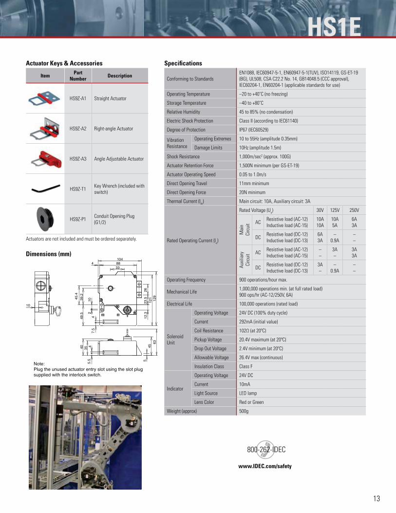
HS1EActuator Keys & Accessories
Item Part Number Description
HS9Z-A1 Straight Actuator
HS9Z-A2 Right-angle Actuator
HS9Z-A3 Angle Adjustable Actuator
HS9Z-T1Key Wrench (included with
switch)
HS9Z-P1Conduit Opening Plug
(G1/2)
Actuators are not included and must be ordered separately.
Dimensions (mm)
Note: Plug the unused actuator entry slot using the slot plug supplied with the interlock switch.
4
4039
.2
12.3
6345
47.
5
10
45.4
3388
49.5
129
121
102
104
5.5
4
23.5
26
35
5
Specifications
Conforming to Standards
EN1088, IEC60947-5-1, EN60947-5-1(TUV), ISO14119, GS-ET-19
(BG), UL508, CSA C22.2 No. 14, GB14048.5 (CCC approval),
IEC60204-1, EN60204-1 (applicable standards for use)
Operating Temperature –20 to +40˚C (no freezing)
Storage Temperature –40 to +80˚C
Relative Humidity 45 to 85% (no condensation)
Electric Shock Protection Class II (according to IEC61140)
Degree of Protection IP67 (IEC60529)
Vibration
Resistance
Operating Extremes 10 to 55Hz (amplitude 0.35mm)
Damage Limits 10Hz (amplitude 1.5m)
Shock Resistance 1,000m/sec2 (approx. 100G)
Actuator Retention Force 1,500N minimum (per GS-ET-19)
Actuator Operating Speed 0.05 to 1.0m/s
Direct Opening Travel 11mm minimum
Direct Opening Force 20N minimum
Thermal Current (Ith) Main circuit: 10A, Auxiliary circuit: 3A
Rated Operating Current (Ie)
Rated Voltage (Ue) 30V 125V 250V
Mai
n
Cir
cuit AC
Resistive load (AC-12)
Inductive load (AC-15)
10A
10A
10A
5A
6A
3A
DCResistive load (DC-12)
Inductive load (DC-13)
6A
3A
–
0.9A
–
–A
uxili
ary
Cir
cuit AC
Resistive load (AC-12)
Inductive load (AC-15)
–
–
3A
–
3A
3A
DCResistive load (DC-12)
Inductive load (DC-13)
3A
–
–
0.9A
–
–
Operating Frequency 900 operations/hour max.
Mechanical Life1,000,000 operations min. (at full rated load)
900 ops/hr (AC-12/250V, 6A)
Electrical Life 100,000 operations (rated load)
Solenoid
Unit
Operating Voltage 24V DC (100% duty cycle)
Current 292mA (initial value)
Coil Resistance 102Ω (at 20ºC)
Pickup Voltage 20.4V maximum (at 20ºC)
Drop Out Voltage 2.4V minimum (at 20ºC)
Allowable Voltage 26.4V max (continuous)
Insulation Class Class F
Indicator
Operating Voltage 24V DC
Current 10mA
Light Source LED lamp
Lens Color Red or Green
Weight (approx) 500g
www.IDEC.com/safety
)800-262-IDEC
This document provided by Barr-Thorp Electric Co., Inc. 800-473-9123 www.barr-thorp.com
14
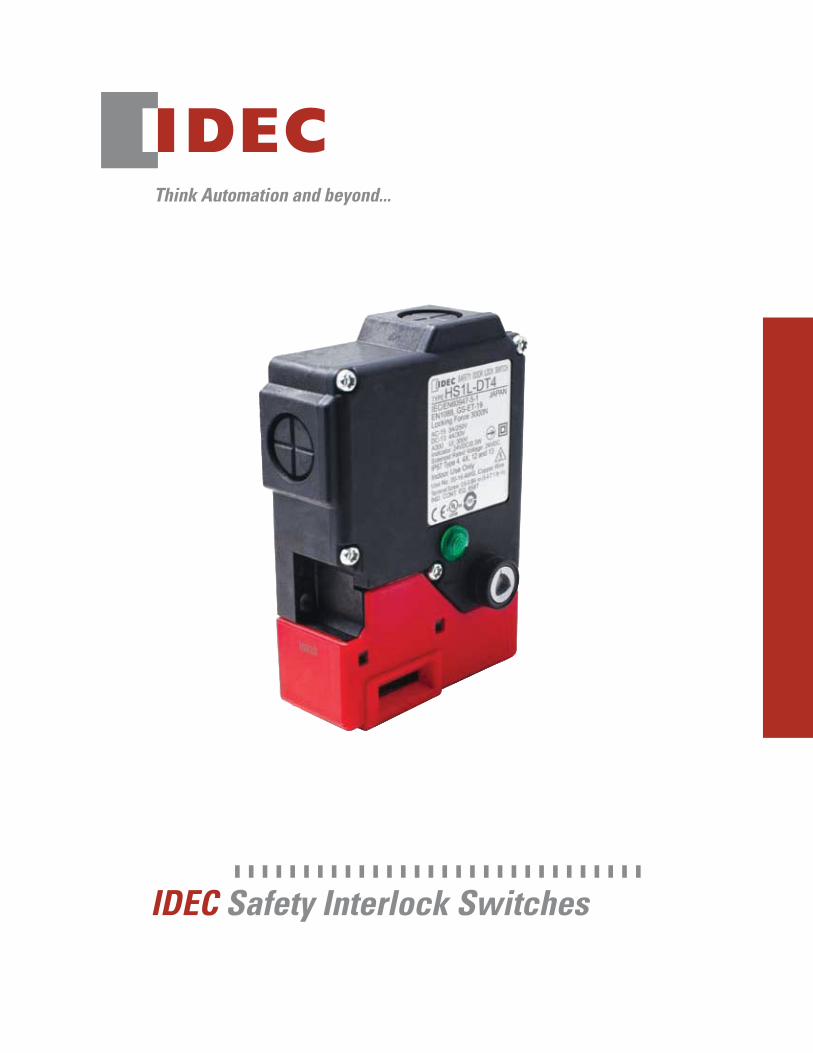
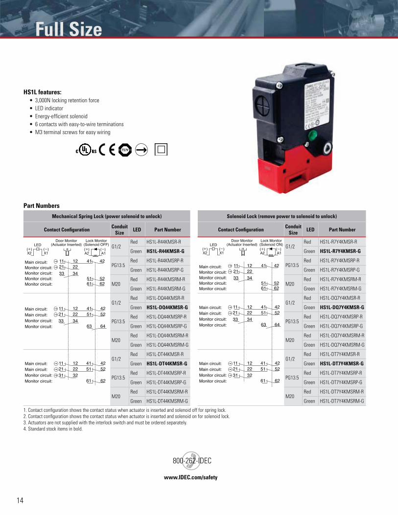
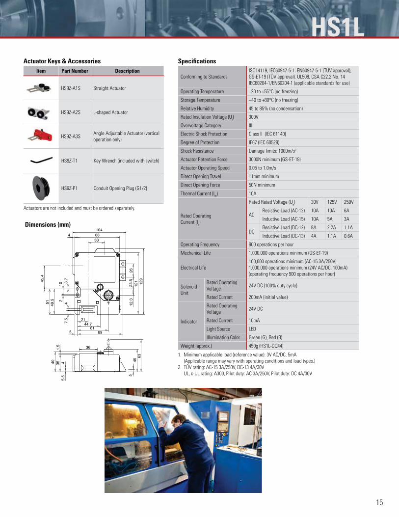
HS1L features:3,000N locking retention force
LED indicator
Energy-efficient solenoid
6 contacts with easy-to-wire terminations
M3 terminal screws for easy wiring
Part Numbers
Mechanical Spring Lock (power solenoid to unlock)
Contact Configuration Conduit Size LED Part Number
Monitor circuit:Monitor circuit:Monitor circuit:Monitor circuit:
222141 421211
33 3451 5261 62
Main circuit:
G1/2Red HS1L-R44KMSR-R
Green HS1L-R44KMSR-G
PG13.5Red HS1L-R44KMSRP-R
Green HS1L-R44KMSRP-G
M20Red HS1L-R44KMSRM-R
Green HS1L-R44KMSRM-G
Main circuit:Main circuit:
Monitor circuit:Monitor circuit:
222141 421211
33 3451 52
63 64
G1/2Red HS1L-DQ44KMSR-R
Green HS1L-DQ44KMSR-G
PG13.5Red HS1L-DQ44KMSRP-R
Green HS1L-DQ44KMSRP-G
M20Red HS1L-DQ44KMSRM-R
Green HS1L-DQ44KMSRM-G
222141 42121151 52
323161 62
Main circuit:Main circuit:
Monitor circuit:Monitor circuit:
G1/2Red HS1L-DT44KMSR-R
Green HS1L-DT44KMSR-G
PG13.5Red HS1L-DT44KMSRP-R
Green HS1L-DT44KMSRP-G
M20Red HS1L-DT44KMSRM-R
Green HS1L-DT44KMSRM-G
Solenoid Lock (remove power to solenoid to unlock)
Contact Configuration Conduit Size LED Part Number
(+)X2
(-)X1
(+)A2
(-) A1
LEDDoor Monitor
(Actuator Inserted)Lock Monitor
(Solenoid ON)
Monitor circuit:Monitor circuit:Monitor circuit:Monitor circuit:
222141 421211
33 3451 5261 62
Main circuit:
G1/2Red HS1L-R7Y4KMSR-R
Green HS1L-R7Y4KMSR-G
PG13.5Red HS1L-R7Y4KMSRP-R
Green HS1L-R7Y4KMSRP-G
M20Red HS1L-R7Y4KMSRM-R
Green HS1L-R7Y4KMSRM-G
Main circuit:Main circuit:
Monitor circuit:Monitor circuit:
222141 421211
33 3451 52
63 64
G1/2Red HS1L-DQ7Y4KMSR-R
Green HS1L-DQ7Y4KMSR-G
PG13.5Red HS1L-DQ7Y4KMSRP-R
Green HS1L-DQ7Y4KMSRP-G
M20Red HS1L-DQ7Y4KMSRM-R
Green HS1L-DQ7Y4KMSRM-G
222141 42121151 52
323161 62
Main circuit:Main circuit:
Monitor circuit:Monitor circuit:
G1/2Red HS1L-DT7Y4KMSR-R
Green HS1L-DT7Y4KMSR-G
PG13.5Red HS1L-DT7Y4KMSRP-R
Green HS1L-DT7Y4KMSRP-G
M20Red HS1L-DT7Y4KMSRM-R
Green HS1L-DT7Y4KMSRM-G
1. Contact configuration shows the contact status when actuator is inserted and solenoid off for spring lock.
2. Contact configuration shows the contact status when actuator is inserted and solenoid on for solenoid lock.
3. Actuators are not supplied with the interlock switch and must be ordered separately.
4. Standard stock items in bold.
(+)X2
(-)X1
(+)A2
(-) A1
LEDDoor Monitor
(Actuator Inserted)Lock Monitor
(Solenoid OFF)
www.IDEC.com/safety
)800-262-IDEC
Full Size
This document provided by Barr-Thorp Electric Co., Inc. 800-473-9123 www.barr-thorp.com
15
Actuator Keys & AccessoriesItem Part Number Description
HS9Z-A1S Straight Actuator
HS9Z-A2S L-shaped Actuator
HS9Z-A3SAngle Adjustable Actuator (vertical
operation only)
HS9Z-T1 Key Wrench (included with switch)
HS9Z-P1 Conduit Opening Plug (G1/2)
Actuators are not included and must be ordered separately.
Dimensions (mm)
44.7
3.7
40 351.
5
8961
21
4104
4 12.3
36
45.4
7.5
88
49.5
129
121
102
5.5
4
23.5
26
51
5
33
5
4563
Specifications
Conforming to Standards
ISO14119, IEC60947-5-1. EN60947-5-1 (TÜV approval),
GS-ET-19 (TÜV approval). UL508, CSA C22.2 No. 14
IEC60204-1/EN60204-1 (applicable standards for use)
Operating Temperature −20 to +55°C (no freezing)
Storage Temperature –40 to +80°C (no freezing)
Relative Humidity 45 to 85% (no condensation)
Rated Insulation Voltage (Ui) 300V
Overvoltage Category III
Electric Shock Protection Class II (IEC 61140)
Degree of Protection IP67 (IEC 60529)
Shock Resistance Damage limits: 1000m/s2
Actuator Retention Force 3000N minimum (GS-ET-19)
Actuator Operating Speed 0.05 to 1.0m/s
Direct Opening Travel 11mm minimum
Direct Opening Force 50N minimum
Thermal Current (Ith) 10A
Rated Operating
Current (Ie)
Rated Rated Voltage (Ue) 30V 125V 250V
ACResistive Load (AC-12) 10A 10A 6A
Inductive Load (AC-15) 10A 5A 3A
DCResistive Load (DC-12) 8A 2.2A 1.1A
Inductive Load (DC-13) 4A 1.1A 0.6A
Operating Frequency 900 operations per hour
Mechanical Life 1,000,000 operations minimum (GS-ET-19)
Electrical Life
100,000 operations minimum (AC-15 3A/250V)
1,000,000 operations minimum (24V AC/DC, 100mA)
(operating frequency 900 operations per hour)
Solenoid
Unit
Rated Operating
Voltage24V DC (100% duty cycle)
Rated Current 200mA (initial value)
Indicator
Rated Operating
Voltage24V DC
Rated Current 10mA
Light Source LED
Illumination Color Green (G), Red (R)
Weight (approx.) 450g (HS1L-DQ44)
1. Minimum applicable load (reference value): 3V AC/DC, 5mA
(Applicable range may vary with operating conditions and load types.)
2. TÜV rating: AC-15 3A/250V, DC-13 4A/30V
UL, c-UL rating: A300, Pilot duty: AC 3A/250V, Pilot duty: DC 4A/30V
HS1L
This document provided by Barr-Thorp Electric Co., Inc. 800-473-9123 www.barr-thorp.com
16
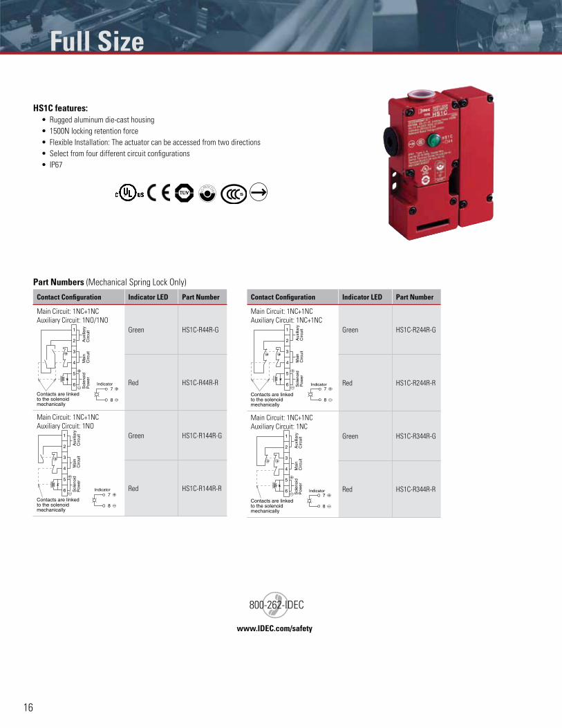
HS1C features:Rugged aluminum die-cast housing
1500N locking retention force
Flexible Installation: The actuator can be accessed from two directions
Select from four different circuit configurations
IP67
Part Numbers (Mechanical Spring Lock Only)
Contact Configuration Indicator LED Part Number
Main Circuit: 1NC+1NC
Auxiliary Circuit: 1NO/1NO
Aux
iliar
yC
ircui
tM
ain
Circ
uit
Sol
enoi
dP
ower
Indicator
Contacts are linkedto the solenoidmechanically
+
– +
–
6
2
1
3
4
5
8
7
Green HS1C-R44R-G
Red HS1C-R44R-R
Main Circuit: 1NC+1NC
Auxiliary Circuit: 1NO
7
8
6
2
1
3
4
5
+
–
+
–
Aux
iliar
yC
ircui
tM
ain
Circ
uit
Sol
enoi
dP
ower
Indicator
Contacts are linkedto the solenoidmechanically
Green HS1C-R144R-G
Red HS1C-R144R-R
Contact Configuration Indicator LED Part Number
Main Circuit: 1NC+1NC
Auxiliary Circuit: 1NC+1NC
Aux
iliar
yC
ircui
tM
ain
Circ
uit
Sol
enoi
dP
ower
7
8
6
2
1
3
4
5
+
–
+
–Indicator
Contacts are linkedto the solenoidmechanically
Green HS1C-R244R-G
Red HS1C-R244R-R
Main Circuit: 1NC+1NC
Auxiliary Circuit: 1NC
7
8
6
2
1
3
4
5
+
–
+
–
Aux
iliar
yC
ircui
tM
ain
Circ
uit
Sol
enoi
dP
ower
Indicator
Contacts are linkedto the solenoidmechanically
Green HS1C-R344R-G
Red HS1C-R344R-R
www.IDEC.com/safety
)800-262-IDEC
Full Size
This document provided by Barr-Thorp Electric Co., Inc. 800-473-9123 www.barr-thorp.com
17
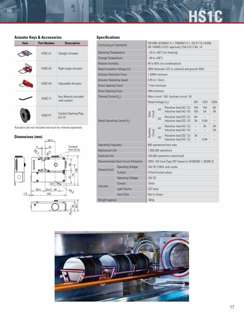
Actuator Keys & AccessoriesItem Part Number Description
HS9Z-A1 Straight Actuator
HS9Z-A2 Right-angle Actuator
HS9Z-A3 Adjustable Actuator
HS9Z-T1Key Wrench (included
with switch)
HS9Z-P1Conduit Opening Plug
(G1/2)
Actuators are not included and must be ordered separately.
Dimensions (mm)
23.5
1.5
10
106
125
2
47
R2.7
ø5.4
42
36.5
49.5 26 ø5.2
7439
.735
4
ConduitPort G1/2
Specifications
Conforming to StandardsEN1088, IEC60947-5-1, EN60947-5-1, GS-ET-19, UL508,
GB 140485.5 (CCC approval), CSA C22.2 No. 14
Operating Temperature –20 to +40˚C (no freezing)
Storage Temperature –40 to +80˚C
Relative Humidity 40 to 85% (no condensation)
Rated Insulation Voltage (Ui) 300V (between LED or solenoid and ground: 60V)
Actuator Retention Force 1,500N minimum
Actuator Operating Speed 0.05 to 1.0m/s
Direct Opening Travel 11mm minimum
Direct Opening Force 20N minimum
Thermal Current (Ith) Main circuit: 10A, Auxiliary circuit: 3A
Rated Operating Current (Ie)
Rated Voltage (Ue) 30V 125V 250V
Mai
n
Cir
cuit AC
Resistive load (AC-12)
Inductive load (AC-15)
10A
10A
10A
5A
6A
3A
DCResistive load (DC-12)
Inductive load (DC-13)
6A
3A
–
0.9A
–
–
Aux
iliar
y
Cir
cuit AC
Resistive load (AC-12)
Inductive load (AC-15)
–
–
3A
–
3A
3A
DCResistive load (DC-12)
Inductive load (DC-13)
3A
–
–
0.9A
–
–
Operating Frequency 900 operations/hour max.
Mechanical Life 1,000,000 operations
Electrical Life 100,000 operations (rated load)
Recommended Short Circuit Protection 250V, 10A fuse (Type D01 based on IEC60269-1, 60269-2)
Solenoid UnitOperating Voltage 24V DC (100% duty cycle)
Current 415mA (initial value)
Indicator
Operating Voltage 24V DC
Current 10mA
Light Source LED lamp
Lens Color Red or Green
Weight (approx) 660g
HS1C
This document provided by Barr-Thorp Electric Co., Inc. 800-473-9123 www.barr-thorp.com

18
Additional Safety Products FS1A Safety Controllers - Consolidate Multiple Safety Relays to One SmartSafety Relay ¢
FS1A features:No programming required
Easily replaces 2 - 3 safety relay control modules
8 or 24 pre-programmed logic safety circuits
Connect with various types of safety inputs
Monitor status of safety I/Os and error codes
IEC 61508 integrity level 3, ISO 13849-1 performance level e
and EN954-1 safety category 4 compliant
When you want a straightforward system that’s safe, easy-to-install and won’t
cost an arm and a leg, an IDEC SafetyOne FS1A is the answer! The FS1A
offers up to 24 pre-programmed logic safety circuits. That means you can
configure a system without any programming, just by selecting one logic from
either 8 (FS1A-C01S) or 24 (FS1A-C11S) to configure a safety system.
Unlike multiple safety relays, which require lots of cumbersome wiring and take
up too much space, the entry-level safety controller makes it easy to consolidate
basic safety circuits. At the same time they save space and minimize wiring.
FS1A SafetyOne can easily replace two to three safety relay control modules
with no programming required. Not only that, SafetyOne can be configured
simply by flipping dip switches to select a logic. One module can connect with
various safety components such as Emergency Stop switches, light curtains,
Interlock switches, two hand controls and auxiliary components such as muting
lights, sensors and much more.
FS1A is UL listed, TUV rated and CE marked, as well as meets IEC 61508 integrity
level 3, ISO 13849-1 performance level e and EN954-1 safety category 4.
72 mm
114.5 mm
113.5 mm
Monitor Output
Replaces more than seven safety relay modules
Four safety output lines
Muting function of light curtains
Mode selection
Solenoid drive output
Light curtains
Muting lamp
Muting sensorsHazardousarea
Object
Safety Input
Solenoid drive output
Monitor signals
Error signals
Safety Outputs
EnablingSwitch
LightCurtain
EmergencyStopSwitch
InterlockSwitch
SelectorSwitch
SafetyOutput 1
SafetyOutput 2
Two-handControl
EmergencyStop Switch
Light Curtain(PNP)
InterlockSwitch Safety
Output 1
SafetyOutput 2
FS1A-C11SLogic 103
FS1A-C11SLogic 12A
FS1A-C11SLogic 104
PLC
Two-hand Control
EmergencyStop Switch
EnablingSwitch
SelectorSwitch
InterlockSwitch
SafetyOutput 2
SafetyOutput 1-1
SafetyOutput 1-2
SafetyOutput 3
This document provided by Barr-Thorp Electric Co., Inc. 800-473-9123 www.barr-thorp.com
19
www.IDEC.com/safety
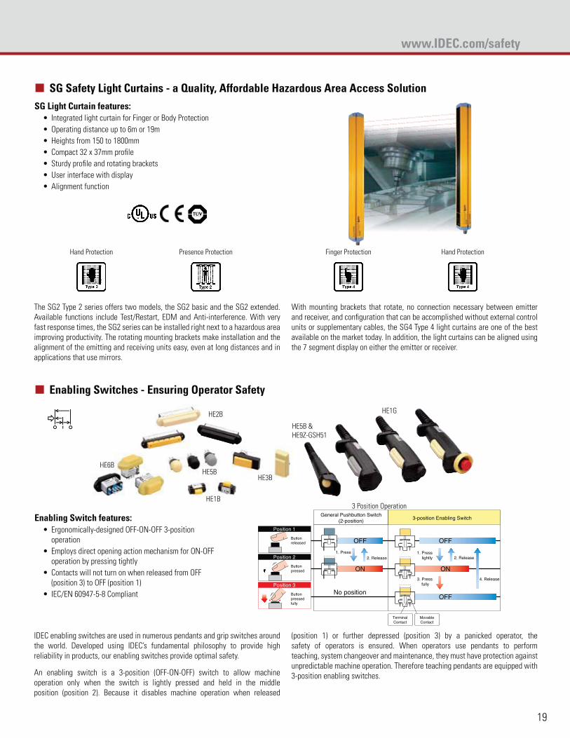
SG Safety Light Curtains - a Quality, Affordable Hazardous Area Access Solution ¢
SG Light Curtain features:Integrated light curtain for Finger or Body Protection
Operating distance up to 6m or 19m
Heights from 150 to 1800mm
Compact 32 x 37mm profile
Sturdy profile and rotating brackets
User interface with display
Alignment function
Hand Protection Presence Protection
The SG2 Type 2 series offers two models, the SG2 basic and the SG2 extended.
Available functions include Test/Restart, EDM and Anti-interference. With very
fast response times, the SG2 series can be installed right next to a hazardous area
improving productivity. The rotating mounting brackets make installation and the
alignment of the emitting and receiving units easy, even at long distances and in
applications that use mirrors.
Finger Protection Hand Protection
With mounting brackets that rotate, no connection necessary between emitter
and receiver, and configuration that can be accomplished without external control
units or supplementary cables, the SG4 Type 4 light curtains are one of the best
available on the market today. In addition, the light curtains can be aligned using
the 7 segment display on either the emitter or receiver.
Enabling Switches - Ensuring Operator Safety ¢
HE2B
HE3BHE5B
HE1G
HE1B
HE6B
HE5B &
HE9Z-GSH51
Enabling Switch features:Ergonomically-designed OFF-ON-OFF 3-position
operation
Employs direct opening action mechanism for ON-OFF
operation by pressing tightly
Contacts will not turn on when released from OFF
(position 3) to OFF (position 1)
IEC/EN 60947-5-8 Compliant
3 Position Operation
TerminalContact
MovableContact
Position 1
General Pushbutton Switch(2-position) 3-position Enabling Switch
OFF
OFF
ON
OFF
ON
No position
1. Press 1. Presslightly
3. Pressfully
4. Release
2. Release 2. Release
Buttonreleased
Position 2
Buttonpressed
Position 3
Buttonpressedfully
IDEC enabling switches are used in numerous pendants and grip switches around
the world. Developed using IDEC’s fundamental philosophy to provide high
reliability in products, our enabling switches provide optimal safety.
An enabling switch is a 3-position (OFF-ON-OFF) switch to allow machine
operation only when the switch is lightly pressed and held in the middle
position (position 2). Because it disables machine operation when released
(position 1) or further depressed (position 3) by a panicked operator, the
safety of operators is ensured. When operators use pendants to perform
teaching, system changeover and maintenance, they must have protection against
unpredictable machine operation. Therefore teaching pendants are equipped with
3-position enabling switches.
This document provided by Barr-Thorp Electric Co., Inc. 800-473-9123 www.barr-thorp.com
USAIDEC CorporationTel: (408) [email protected]
CanadaIDEC Canada Ltd.Tel: (905) [email protected]
AustraliaIDEC Australia Pty. Ltd.Tel: [email protected]
JapanIDEC CorporationTel: +81-6-6398-2571 [email protected]
United KingdomIDEC Electronics Ltd.Tel: +44-1256-321000 [email protected]
GermanyIDEC Elektrotechnik GmbHTel: [email protected]
Hong KongIDEC (H.K.) Co., Ltd.Tel: +852-2803-8989 [email protected]
China/BeijingIDEC (Beijing) CorporationTel: [email protected]
China/ShanghaiIDEC (Shanghai) CorporationTel: [email protected]
China/ShenzhenIDEC (Shenzhen) CorporationTel: +86-755-8356-2977
SingaporeIDEC Asia Pte. Ltd.Tel: +65-6746-1155 [email protected]
TaiwanIDEC Taiwan CorporationTel: +886-2-2698-3929 [email protected]
©2010 IDEC Corporation. All Rights Reserved. Catalog No. HS9Y-B100-0 12/10 10K
www.IDEC.com
Specifications and other descriptions in this catalog are subject to change without notice.
www.IDEC.com/safety
)800-262-IDEC
Product Information
Safety Productswww.IDEC.com/safety
Product Support
Technical support:[email protected]
Find your local IDECRepresentative or Distributor:www.IDEC.com/usa/locator
Phone: 800-262-IDEC
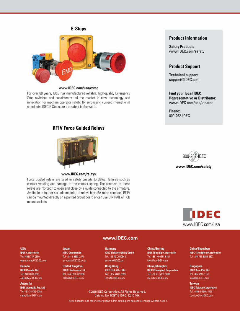
E-Stops
www.IDEC.com/usa/estopFor over 60 years, IDEC has manufactured reliable, high-quality Emergency
Stop switches and consistently led the market in new technology and
innovation for machine operator safety. By surpassing current international
standards, IDEC E-Stops are the safest in the world.
RF1V Force Guided Relays
www.IDEC.com/relaysForce guided relays are used in safety circuits to detect failures such as
contact welding and damage to the contact spring. The contacts of these
relays are “forced” to open and close by a guide connected to the armature.
Available in four or six pole models, all relays have 6A rated contacts. RF1V
can be mounted directly on a printed circuit board or can use DIN RAIL or PCB
mount sockets.
www.IDEC.com/usa
This document provided by Barr-Thorp Electric Co., Inc. 800-473-9123 www.barr-thorp.com