Embed Size (px)
Citation preview
© 2014 Microchip Technology Incorporated. All Rights Reserved. Interfacing with Vehicle Networks: Best Practices Slide 1
18060 IVN
Interfacing with Vehicle Networks: Best Practices
© 2014 Microchip Technology Incorporated. All Rights Reserved. Interfacing with Vehicle Networks: Best Practices Slide 2
Agenda
Introduction to OBD Lab 1
Power Management Lab 2
Transceiver Design Lab 3
Avoiding Interference
© 2014 Microchip Technology Incorporated. All Rights Reserved. Interfacing with Vehicle Networks: Best Practices Slide 3
Class Objectives
Describe OBD and its applications Access and interpret OBD data Explain power management and
transceiver design considerations Recognize and avoid common
design pitfalls
© 2014 Microchip Technology Incorporated. All Rights Reserved. Interfacing with Vehicle Networks: Best Practices Slide 4
Class Objectives
Choose an appropriate power management strategy
Properly design OBD transceivers, using inexpensive discrete components
Use an OBD simulator for development and testing
© 2014 Microchip Technology Incorporated. All Rights Reserved. Interfacing with Vehicle Networks: Best Practices Slide 5
Class Objectives
Summarize the problems faced by the designers of OBD devices

© 2014 Microchip Technology Incorporated. All Rights Reserved. Interfacing with Vehicle Networks: Best Practices Slide 6
Introduction to OBD
© 2014 Microchip Technology Incorporated. All Rights Reserved. Interfacing with Vehicle Networks: Best Practices Slide 7
Introduction to OBD
What is OBD? Key Terms OBD applications Accessing OBD data
© 2014 Microchip Technology Incorporated. All Rights Reserved. Interfacing with Vehicle Networks: Best Practices Slide 8
What is ‘OBD’?
On-Board Diagnostics Computer-based system
designed to control emissions Provides early warning through
MIL (Malfunction Indicator Light)
© 2014 Microchip Technology Incorporated. All Rights Reserved. Interfacing with Vehicle Networks: Best Practices Slide 9
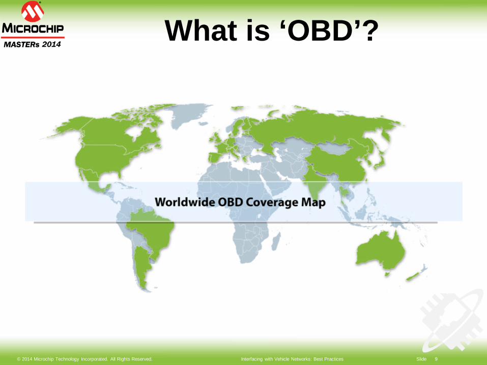
What is ‘OBD’?
© 2014 Microchip Technology Incorporated. All Rights Reserved. Interfacing with Vehicle Networks: Best Practices Slide 10
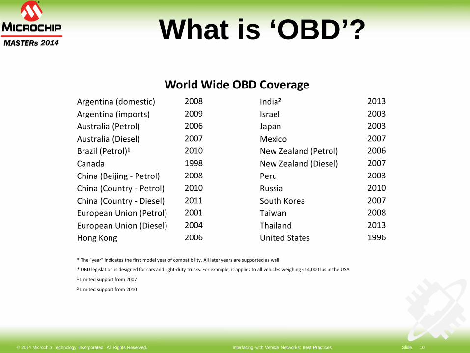
What is ‘OBD’?World Wide OBD Coverage
Argentina (domestic) 2008 India2 2013Argentina (imports) 2009 Israel 2003Australia (Petrol) 2006 Japan 2003Australia (Diesel) 2007 Mexico 2007Brazil (Petrol)1 2010 New Zealand (Petrol) 2006Canada 1998 New Zealand (Diesel) 2007China (Beijing - Petrol) 2008 Peru 2003China (Country - Petrol) 2010 Russia 2010China (Country - Diesel) 2011 South Korea 2007European Union (Petrol) 2001 Taiwan 2008European Union (Diesel) 2004 Thailand 2013Hong Kong 2006 United States 1996
* The "year" indicates the first model year of compatibility. All later years are supported as well
* OBD legislation is designed for cars and light-duty trucks. For example, it applies to all vehicles weighing <14,000 lbs in the USA
1 Limited support from 2007
2 Limited support from 2010
© 2014 Microchip Technology Incorporated. All Rights Reserved. Interfacing with Vehicle Networks: Best Practices Slide 11
Key Terms
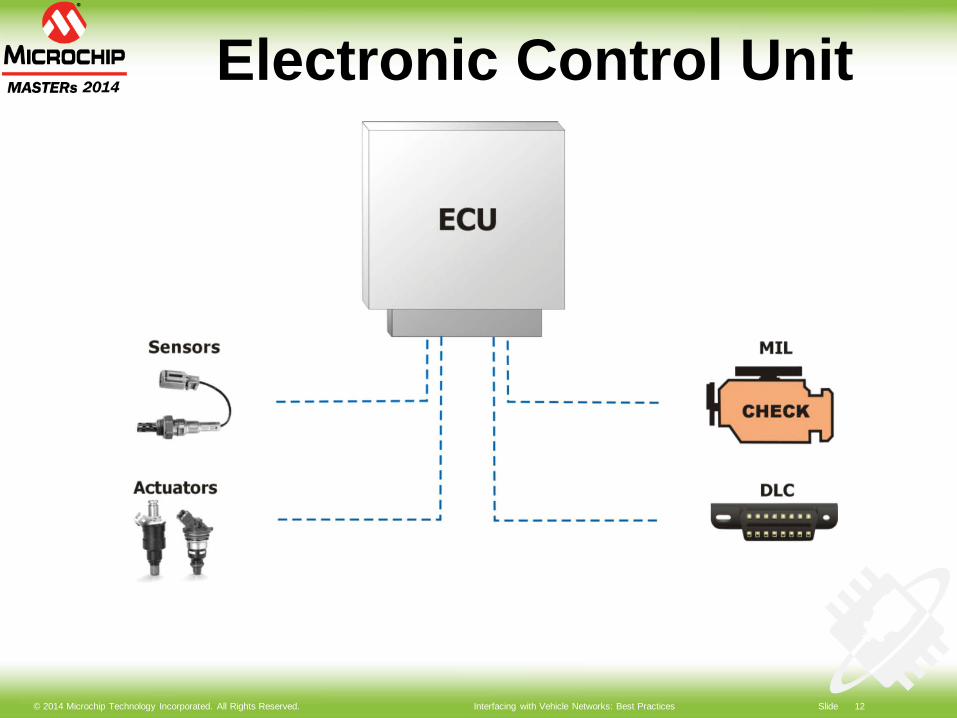
ECU: Electronic Control Unit MIL: Malfunction Indicator Light
(“Check Engine”) DLC: Diagnostic Link Connector
(“OBD Port”) DTC: Diagnostic Trouble Code CAN: Controller Area Network
© 2014 Microchip Technology Incorporated. All Rights Reserved. Interfacing with Vehicle Networks: Best Practices Slide 12
Electronic Control Unit
© 2014 Microchip Technology Incorporated. All Rights Reserved. Interfacing with Vehicle Networks: Best Practices Slide 13
ECU Types
PCM: Powertrain Control Module ECM: Engine TCM: Transmission BCM: Body Other: ABS/ESC, SRS, HVAC,
immobilizer, etc
© 2014 Microchip Technology Incorporated. All Rights Reserved. Interfacing with Vehicle Networks: Best Practices Slide 14
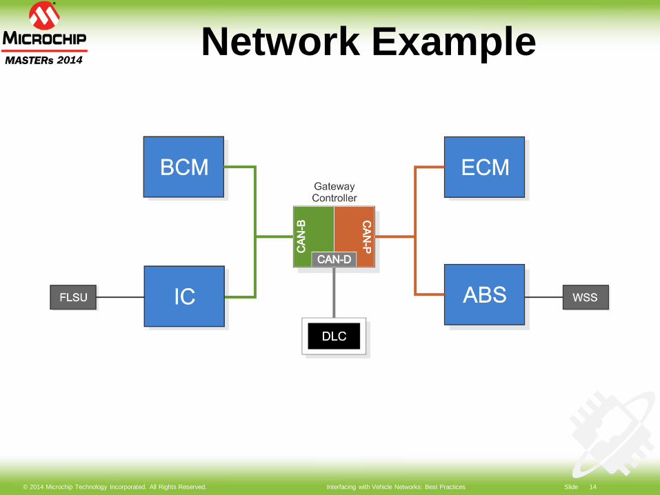
Network Example
© 2014 Microchip Technology Incorporated. All Rights Reserved. Interfacing with Vehicle Networks: Best Practices Slide 15
OBD Applications
Diagnostics Performance Tuning/Reflashing Fleet Management Telematics/Vehicle Tracking Usage-based Insurance (UBI) Driver Behavior
Monitoring/Feedback
© 2014 Microchip Technology Incorporated. All Rights Reserved. Interfacing with Vehicle Networks: Best Practices Slide 16
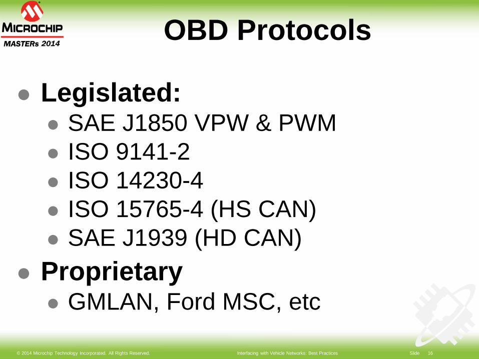
OBD Protocols
Legislated: SAE J1850 VPW & PWM ISO 9141-2 ISO 14230-4 ISO 15765-4 (HS CAN) SAE J1939 (HD CAN)
Proprietary GMLAN, Ford MSC, etc
© 2014 Microchip Technology Incorporated. All Rights Reserved. Interfacing with Vehicle Networks: Best Practices Slide 17
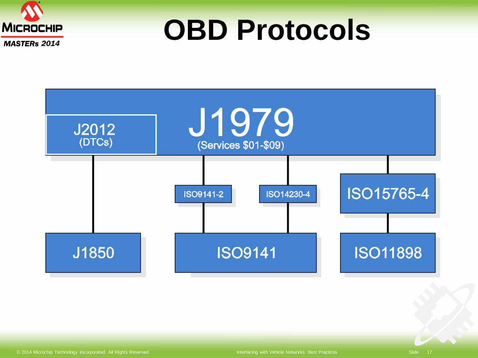
OBD Protocols
© 2014 Microchip Technology Incorporated. All Rights Reserved. Interfacing with Vehicle Networks: Best Practices Slide 18
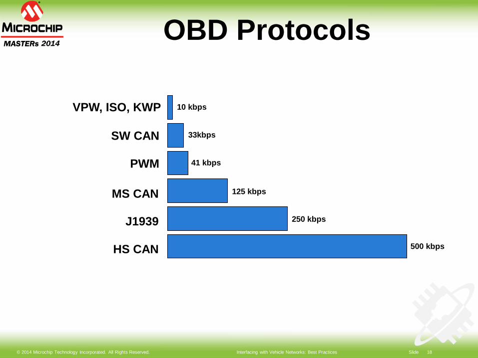
OBD Protocols
VPW, ISO, KWP
PWM
J1939
10 kbps
41 kbps
SW CAN
HS CAN
33kbps
500 kbps
250 kbps
MS CAN 125 kbps
© 2014 Microchip Technology Incorporated. All Rights Reserved. Interfacing with Vehicle Networks: Best Practices Slide 19
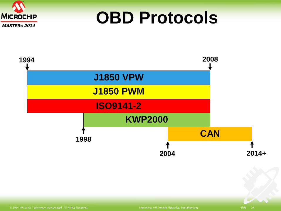
OBD Protocols
1994 2008
J1850 VPW
1998
ISO9141-2J1850 PWM
KWP2000CAN
2004 2014+
© 2014 Microchip Technology Incorporated. All Rights Reserved. Interfacing with Vehicle Networks: Best Practices Slide 20
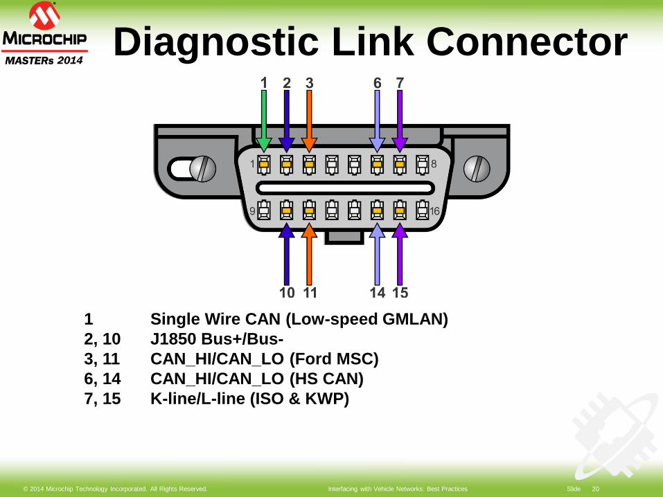
Diagnostic Link Connector
1 Single Wire CAN (Low-speed GMLAN)2, 10 J1850 Bus+/Bus-3, 11 CAN_HI/CAN_LO (Ford MSC)6, 14 CAN_HI/CAN_LO (HS CAN)7, 15 K-line/L-line (ISO & KWP)
© 2014 Microchip Technology Incorporated. All Rights Reserved. Interfacing with Vehicle Networks: Best Practices Slide 21
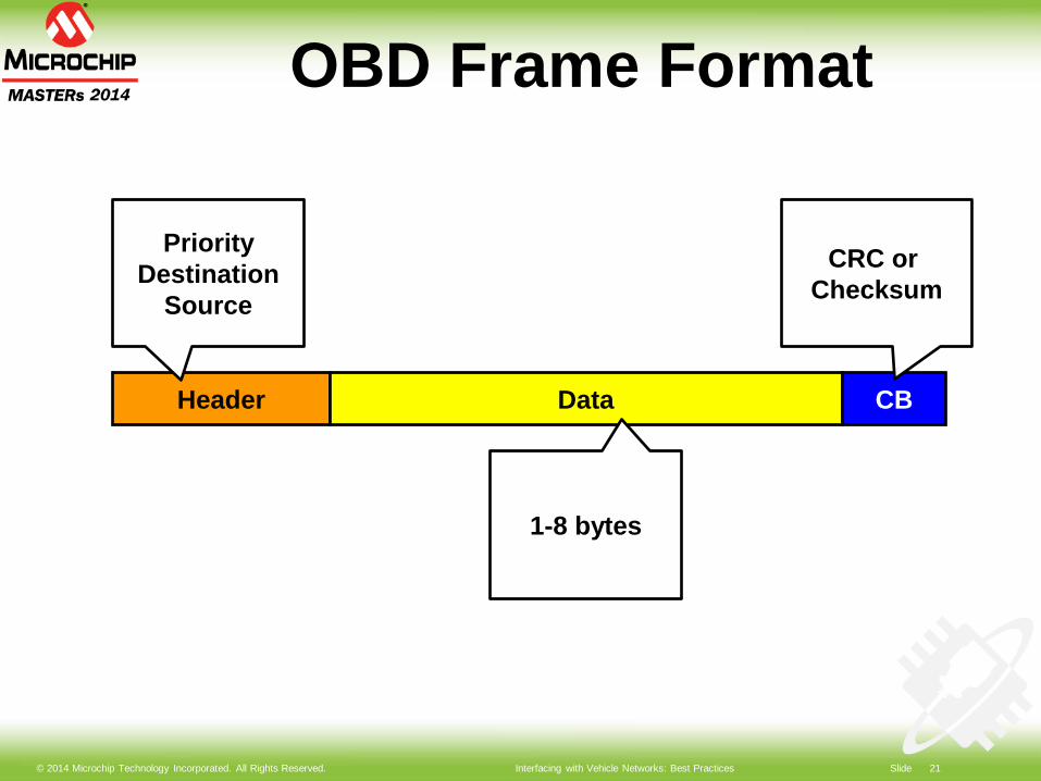
OBD Frame Format
Header Data CB
PriorityDestination
Source
CRC or Checksum
1-8 bytes
© 2014 Microchip Technology Incorporated. All Rights Reserved. Interfacing with Vehicle Networks: Best Practices Slide 22
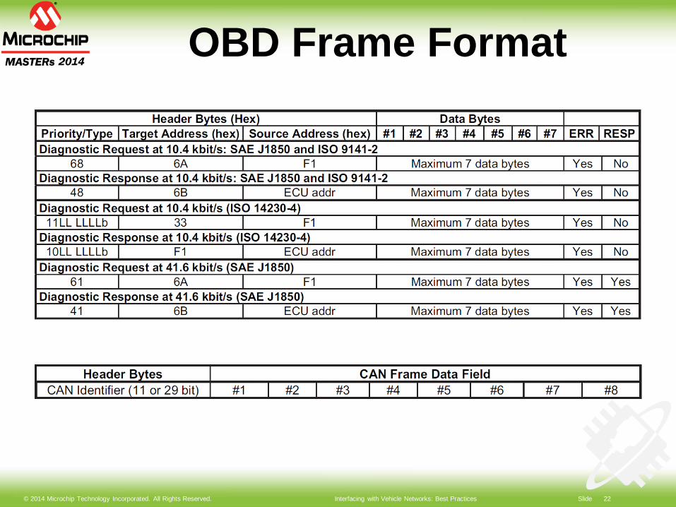
OBD Frame Format
© 2014 Microchip Technology Incorporated. All Rights Reserved. Interfacing with Vehicle Networks: Best Practices Slide 23
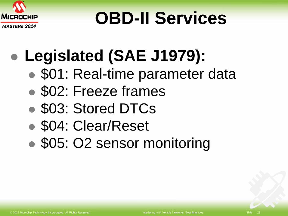
OBD-II Services
Legislated (SAE J1979): $01: Real-time parameter data $02: Freeze frames $03: Stored DTCs $04: Clear/Reset $05: O2 sensor monitoring
© 2014 Microchip Technology Incorporated. All Rights Reserved. Interfacing with Vehicle Networks: Best Practices Slide 24
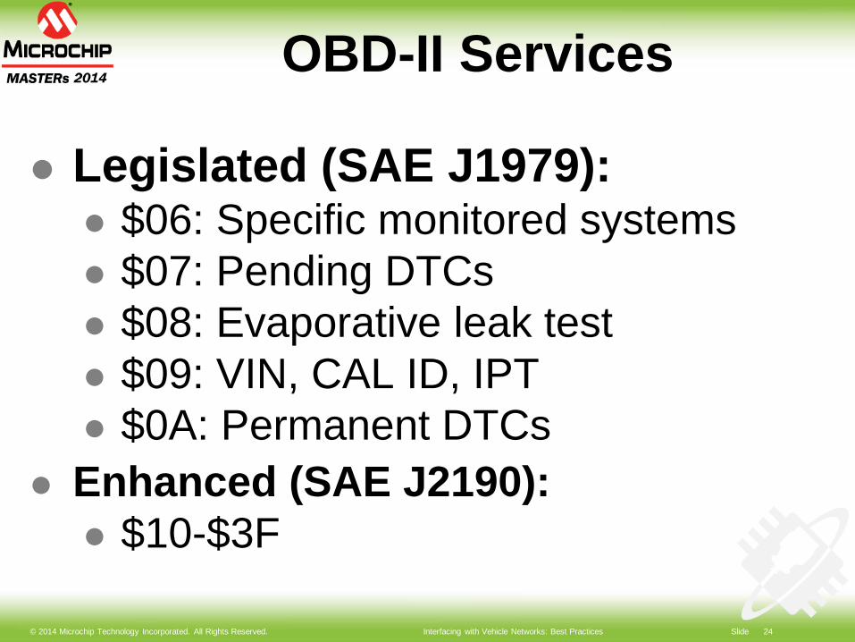
OBD-II Services
Legislated (SAE J1979): $06: Specific monitored systems $07: Pending DTCs $08: Evaporative leak test $09: VIN, CAL ID, IPT $0A: Permanent DTCs
Enhanced (SAE J2190): $10-$3F
© 2014 Microchip Technology Incorporated. All Rights Reserved. Interfacing with Vehicle Networks: Best Practices Slide 25
Lab 1:Access OBD data
© 2014 Microchip Technology Incorporated. All Rights Reserved. Interfacing with Vehicle Networks: Best Practices Slide 26
Lab 1 Objectives
Become familiar w/ dev tools Establish connection with the
simulator Request and interpret data:
vehicle speed, RPM, DTCs, VIN
© 2014 Microchip Technology Incorporated. All Rights Reserved. Interfacing with Vehicle Networks: Best Practices Slide 27
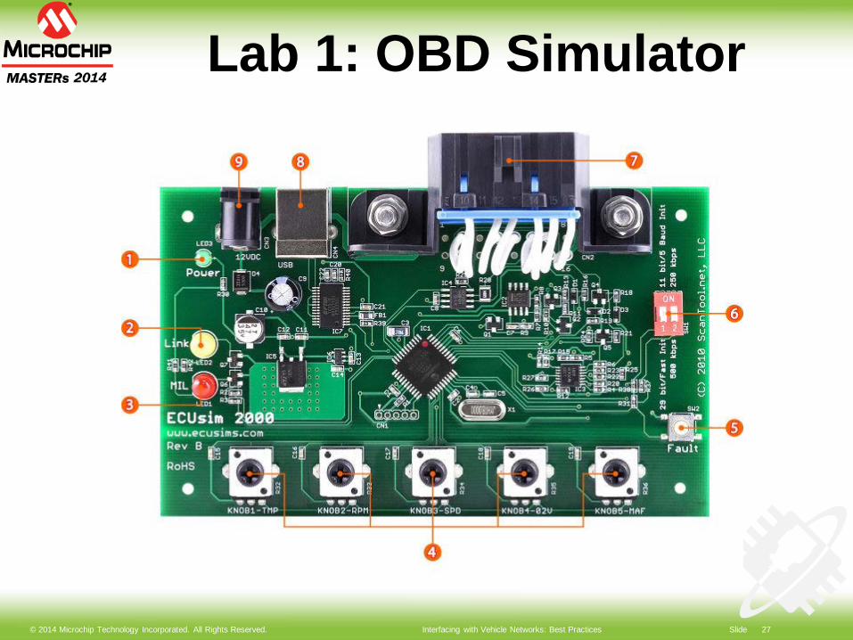
Lab 1: OBD Simulator
© 2014 Microchip Technology Incorporated. All Rights Reserved. Interfacing with Vehicle Networks: Best Practices Slide 28
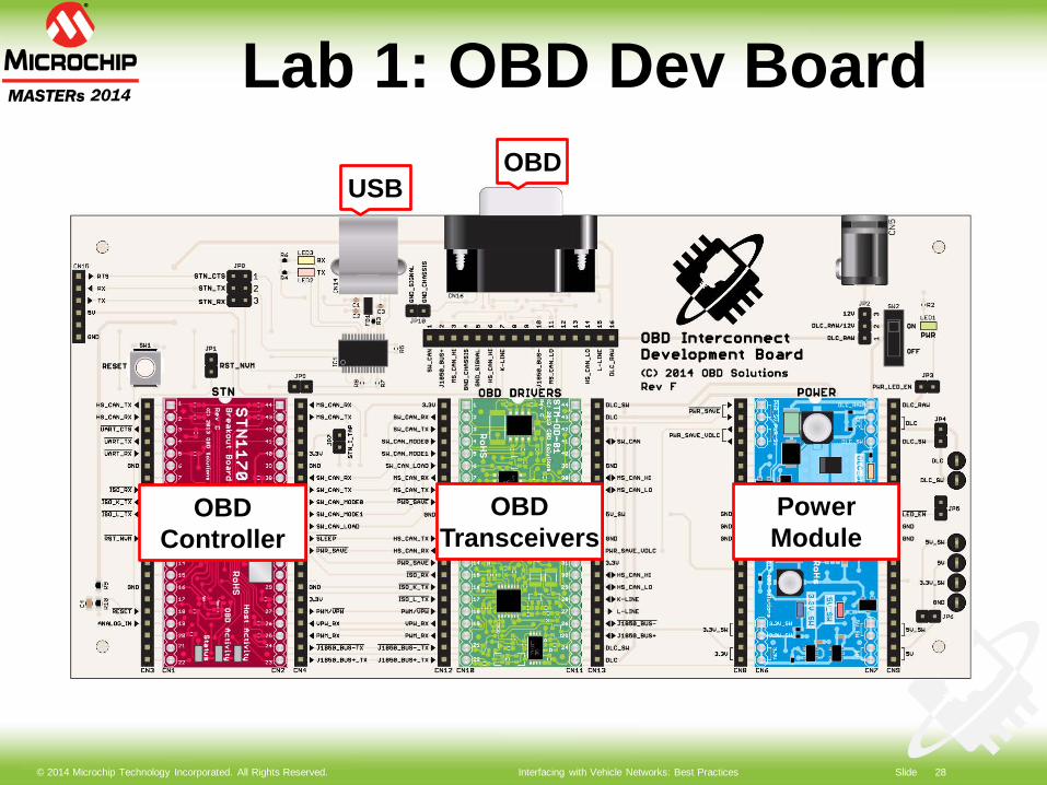
Lab 1: OBD Dev Board
OBDTransceivers
OBDController
PowerModule
USBOBD
© 2014 Microchip Technology Incorporated. All Rights Reserved. Interfacing with Vehicle Networks: Best Practices Slide 29
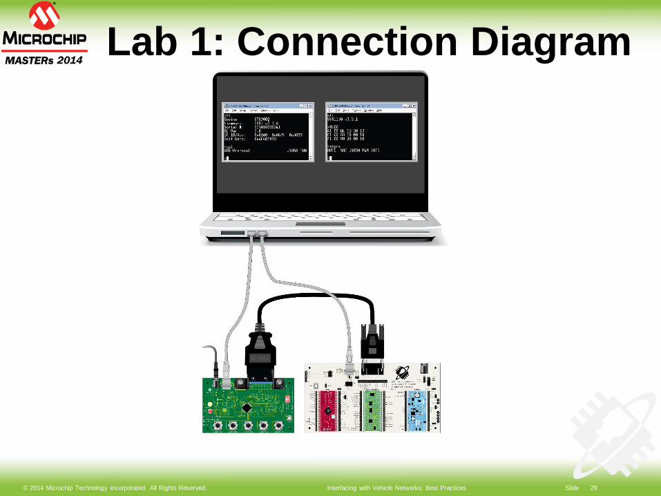
Lab 1: Connection Diagram
© 2014 Microchip Technology Incorporated. All Rights Reserved. Interfacing with Vehicle Networks: Best Practices Slide 30
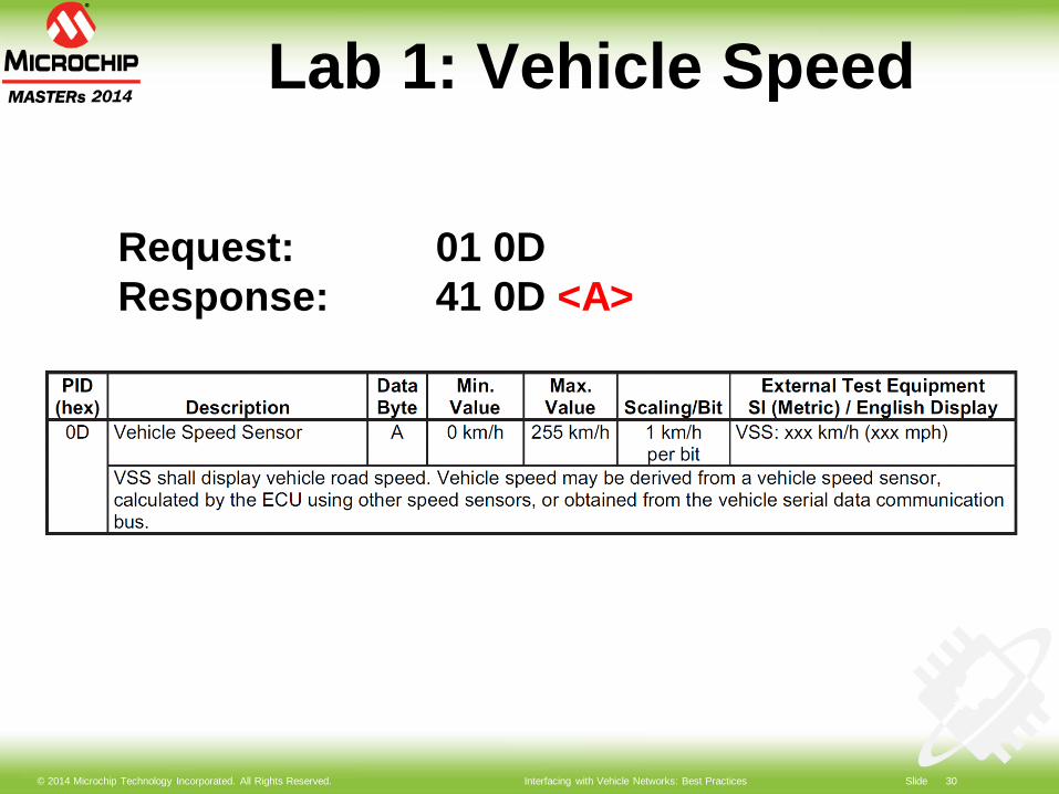
Lab 1: Vehicle Speed
Request: 01 0DResponse: 41 0D <A>
© 2014 Microchip Technology Incorporated. All Rights Reserved. Interfacing with Vehicle Networks: Best Practices Slide 31
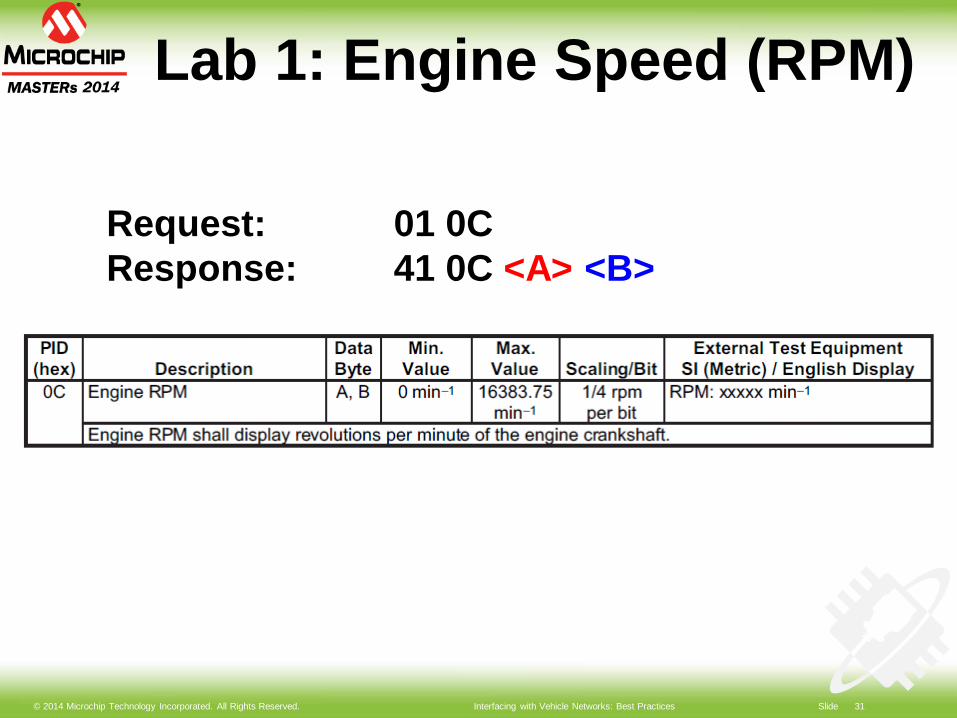
Lab 1: Engine Speed (RPM)
Request: 01 0CResponse: 41 0C <A> <B>

© 2014 Microchip Technology Incorporated. All Rights Reserved. Interfacing with Vehicle Networks: Best Practices Slide 32
Lab 1: DTC structure
© 2014 Microchip Technology Incorporated. All Rights Reserved. Interfacing with Vehicle Networks: Best Practices Slide 33
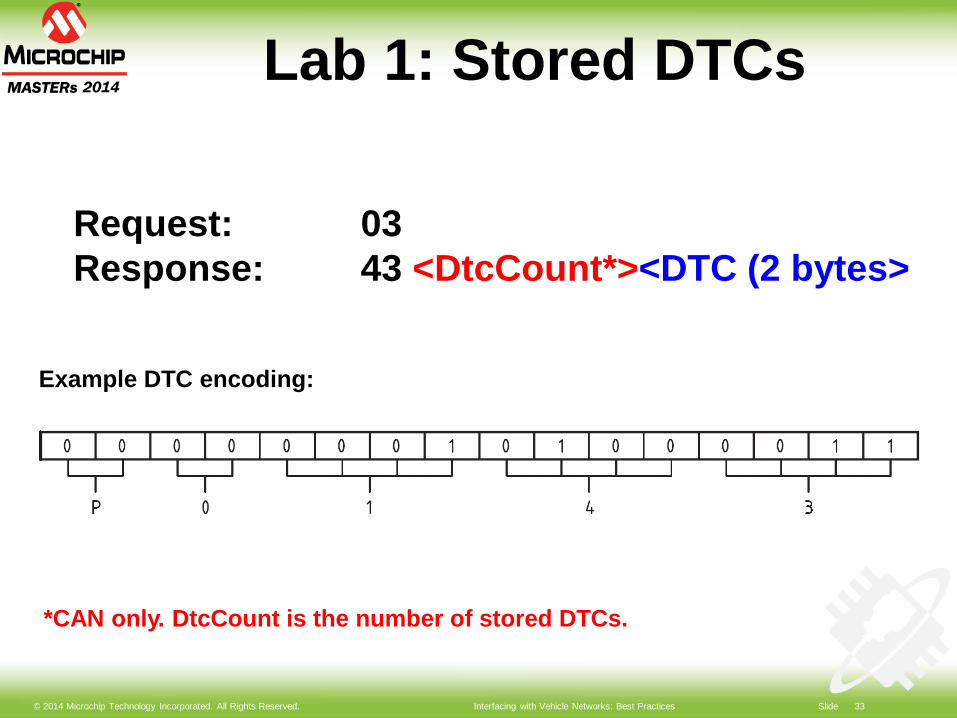
Lab 1: Stored DTCs
Request: 03Response: 43 <DtcCount*><DTC (2 bytes>
*CAN only. DtcCount is the number of stored DTCs.
Example DTC encoding:
© 2014 Microchip Technology Incorporated. All Rights Reserved. Interfacing with Vehicle Networks: Best Practices Slide 34
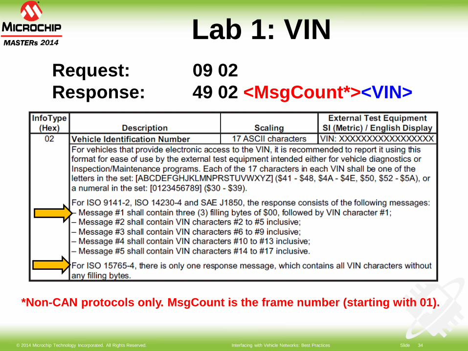
Lab 1: VINRequest: 09 02Response: 49 02 <MsgCount*><VIN>
*Non-CAN protocols only. MsgCount is the frame number (starting with 01).
© 2014 Microchip Technology Incorporated. All Rights Reserved. Interfacing with Vehicle Networks: Best Practices Slide 35
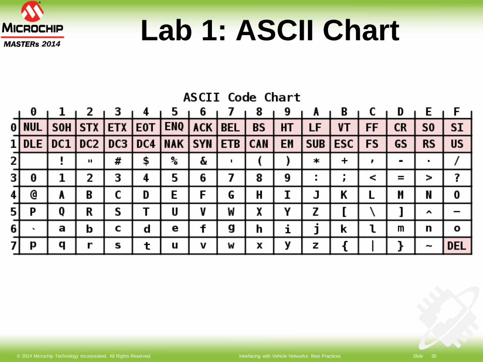
Lab 1: ASCII Chart
© 2014 Microchip Technology Incorporated. All Rights Reserved. Interfacing with Vehicle Networks: Best Practices Slide 36
Lab 1 Summary OBD uses “request/response”
method of information exchange Large chunks of data may be
spread over several OBD frames More than one ECU may respond
to a functional request ISO 15765-4 supports multi-frame
responses as true “messages”

© 2014 Microchip Technology Incorporated. All Rights Reserved. Interfacing with Vehicle Networks: Best Practices Slide 37
Power Management

© 2014 Microchip Technology Incorporated. All Rights Reserved. Interfacing with Vehicle Networks: Best Practices Slide 38
Power Management
Power supply configurations Load dump protection Sleep Strategies Wake-up Strategies Common Pitfalls

© 2014 Microchip Technology Incorporated. All Rights Reserved. Interfacing with Vehicle Networks: Best Practices Slide 39
Power Supply Configurations
Considerations: Current consumption
Peak Operating Sleep (quiescent)
Power dissipation Physical size Functional requirements
© 2014 Microchip Technology Incorporated. All Rights Reserved. Interfacing with Vehicle Networks: Best Practices Slide 40
Power Supply Configurations
Daisy-chain vs. Parallel Linear and/or SMPS Peripherals always on or
switched off in sleep

© 2014 Microchip Technology Incorporated. All Rights Reserved. Interfacing with Vehicle Networks: Best Practices Slide 41
VDLC
Power Supply Configurations
7805 3V(linear)
5V peripherals
OBD controller
12Vperipherals
3Vperipherals
+ Low cost, low part count- High sleep current, high power dissipation
Daisy chained linear regulators

© 2014 Microchip Technology Incorporated. All Rights Reserved. Interfacing with Vehicle Networks: Best Practices Slide 42
VDLC
Power Supply Configurations
7805 3V(linear*)
5V peripherals
OBD controller
12Vperipherals
3Vperipherals
+ Low sleep current- High power dissipation* Must use a 3V regulator with low IQ and a high VMAX
Parallel linear regulators w/ switch
© 2014 Microchip Technology Incorporated. All Rights Reserved. Interfacing with Vehicle Networks: Best Practices Slide 43
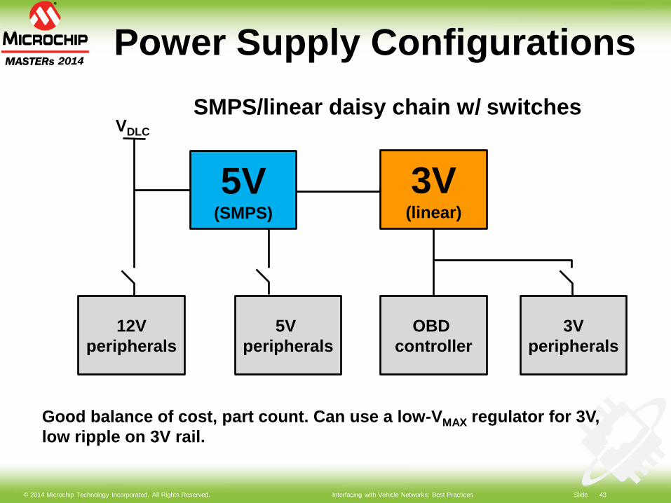
VDLC
Power Supply Configurations
3V(linear)
5V peripherals
OBD controller
12Vperipherals
3Vperipherals
5V(SMPS)
SMPS/linear daisy chain w/ switches
Good balance of cost, part count. Can use a low-VMAX regulator for 3V, low ripple on 3V rail.
© 2014 Microchip Technology Incorporated. All Rights Reserved. Interfacing with Vehicle Networks: Best Practices Slide 44
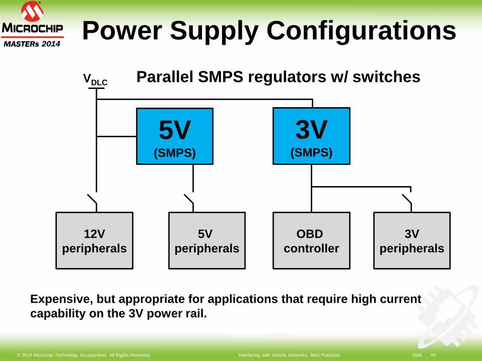
VDLC
Power Supply Configurations
3V(SMPS)
5V peripherals
OBD controller
12Vperipherals
3Vperipherals
5V(SMPS)
Parallel SMPS regulators w/ switches
Expensive, but appropriate for applications that require high current capability on the 3V power rail.
© 2014 Microchip Technology Incorporated. All Rights Reserved. Interfacing with Vehicle Networks: Best Practices Slide 45
Load Dump Protection
Load Dump Battery disconnected while being
charged by alternator Causes: cable corrosion, poor
connection, or intentional disconnection with the engine running
Most new alternators use diodes to suppress (clamp) the pulse
© 2014 Microchip Technology Incorporated. All Rights Reserved. Interfacing with Vehicle Networks: Best Practices Slide 46
Load Dump Protection
Load Dump Pulse Described in ISO 7637-2 Pulse 5a (unsuppressed) Pulse 5b (suppressed)
© 2014 Microchip Technology Incorporated. All Rights Reserved. Interfacing with Vehicle Networks: Best Practices Slide 47
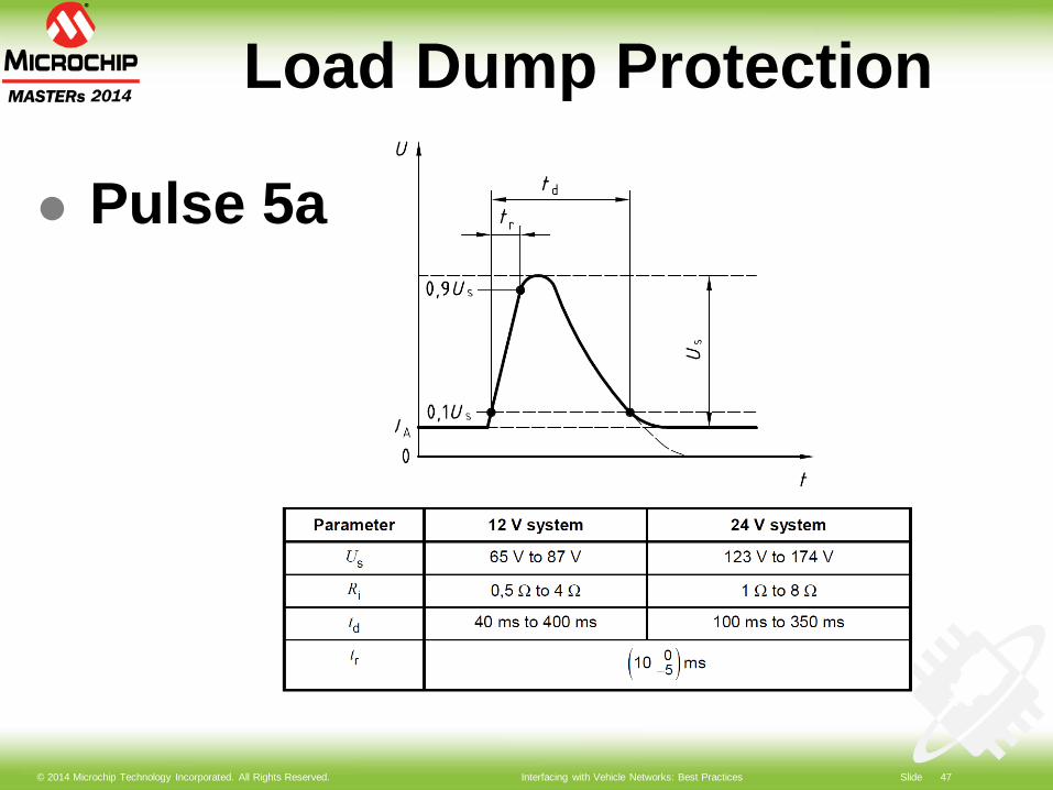
Load Dump Protection
Pulse 5a
© 2014 Microchip Technology Incorporated. All Rights Reserved. Interfacing with Vehicle Networks: Best Practices Slide 48
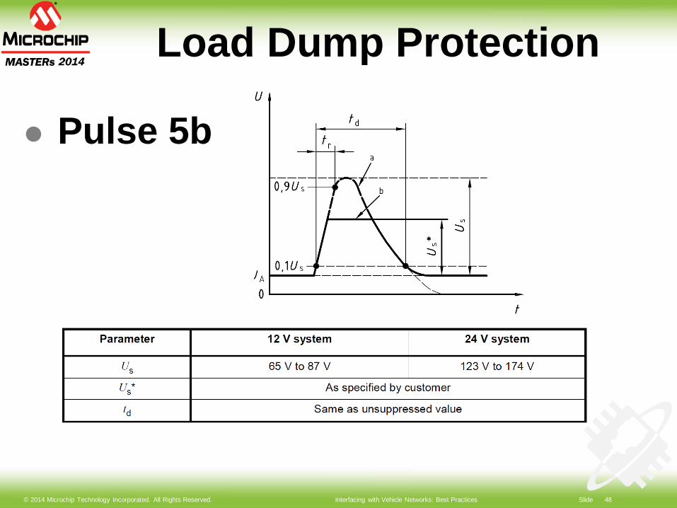
Load Dump Protection
Pulse 5b
© 2014 Microchip Technology Incorporated. All Rights Reserved. Interfacing with Vehicle Networks: Best Practices Slide 49
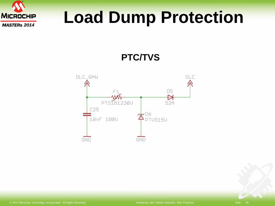
Load Dump Protection
PTC/TVS
© 2014 Microchip Technology Incorporated. All Rights Reserved. Interfacing with Vehicle Networks: Best Practices Slide 50
Load Dump Protection
Pros: Simple Low part count
Cons: Bulky Relatively expensive Gets bulkier/more expensive >60V
© 2014 Microchip Technology Incorporated. All Rights Reserved. Interfacing with Vehicle Networks: Best Practices Slide 51
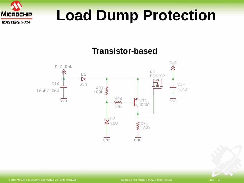
Load Dump Protection
Transistor-based
© 2014 Microchip Technology Incorporated. All Rights Reserved. Interfacing with Vehicle Networks: Best Practices Slide 52
Load Dump Protection
Pros: Inexpensive Can be smaller than PTC/TVS Vmax >90V easily achieved
Cons: Higher part count
© 2014 Microchip Technology Incorporated. All Rights Reserved. Interfacing with Vehicle Networks: Best Practices Slide 53
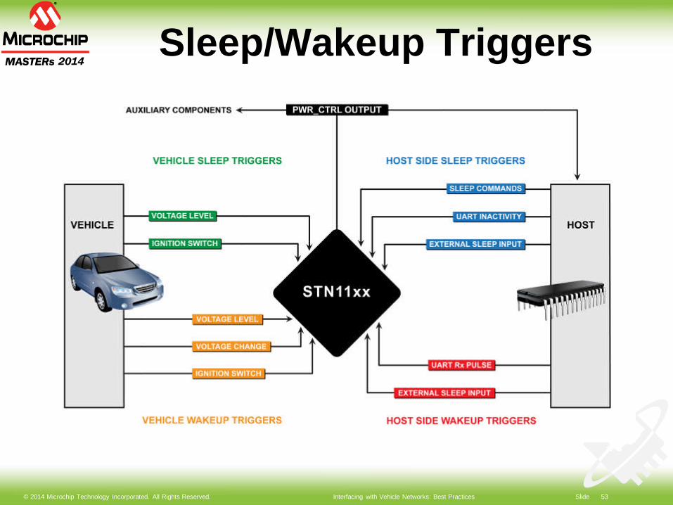
Sleep/Wakeup Triggers
© 2014 Microchip Technology Incorporated. All Rights Reserved. Interfacing with Vehicle Networks: Best Practices Slide 54
Sleep Strategies
Sleep on: Voltage below threshold Communication timeout Explicit “SLEEP” command or level
Always set up wake-up triggers, first
© 2014 Microchip Technology Incorporated. All Rights Reserved. Interfacing with Vehicle Networks: Best Practices Slide 55
Wake-up Strategies
Wake up on: Voltage level Voltage change Comm activity External input pin
© 2014 Microchip Technology Incorporated. All Rights Reserved. Interfacing with Vehicle Networks: Best Practices Slide 56
Common Pitfalls
Interrogating ECUs while engine is off
Leaving peripherals switched on in sleep
Improper regulator selection (IQ and IPEAK)
Insufficient heatsinking

© 2014 Microchip Technology Incorporated. All Rights Reserved. Interfacing with Vehicle Networks: Best Practices Slide 57
Lab 2:Sleep/Wakeup
© 2014 Microchip Technology Incorporated. All Rights Reserved. Interfacing with Vehicle Networks: Best Practices Slide 58
Lab 2 Objectives
Configure wake-up triggers Configure device to go to sleep
after 30 seconds of inactivity Wake device up via UART Put the device to sleep via UART
command Use voltage change for wake-up

© 2014 Microchip Technology Incorporated. All Rights Reserved. Interfacing with Vehicle Networks: Best Practices Slide 59
Lab 2 Summary
Use multiple sleep and wake-up triggers for most reliable operation
Ensure wake-up triggers are enabled, before enabling sleep triggers
© 2014 Microchip Technology Incorporated. All Rights Reserved. Interfacing with Vehicle Networks: Best Practices Slide 60
Transceiver Design
© 2014 Microchip Technology Incorporated. All Rights Reserved. Interfacing with Vehicle Networks: Best Practices Slide 61
Transceiver Design
Design Considerations J1850 transceiver ISO/KWP transceiver Common pitfalls
© 2014 Microchip Technology Incorporated. All Rights Reserved. Interfacing with Vehicle Networks: Best Practices Slide 62
Transceiver Design
Considerations: Functionality Reliability Cost Performance Part count Available resources
© 2014 Microchip Technology Incorporated. All Rights Reserved. Interfacing with Vehicle Networks: Best Practices Slide 63
Transceiver Design
Advantages of Discrete Design Cost ($0.75 vs $3) Availability
HS CAN still requires an IC (e.g., MCP2561-62)
© 2014 Microchip Technology Incorporated. All Rights Reserved. Interfacing with Vehicle Networks: Best Practices Slide 64
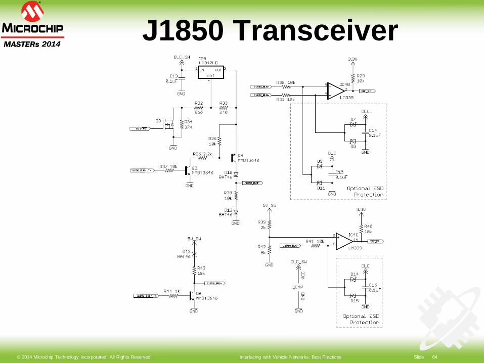
J1850 Transceiver
© 2014 Microchip Technology Incorporated. All Rights Reserved. Interfacing with Vehicle Networks: Best Practices Slide 65
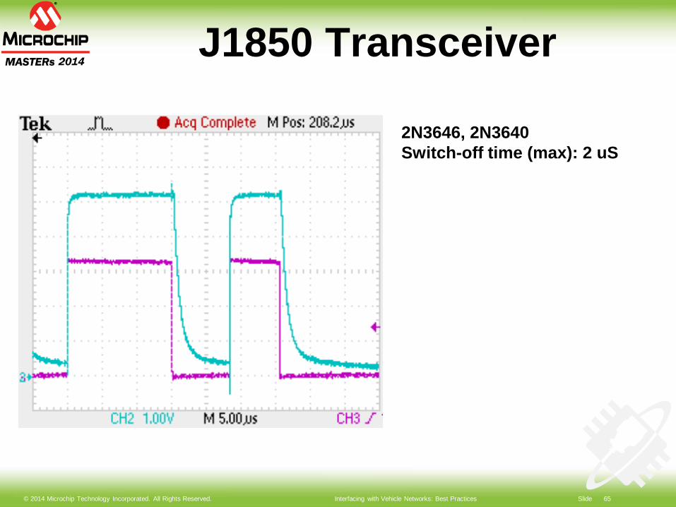
J1850 Transceiver
2N3646, 2N3640Switch-off time (max): 2 uS
© 2014 Microchip Technology Incorporated. All Rights Reserved. Interfacing with Vehicle Networks: Best Practices Slide 66
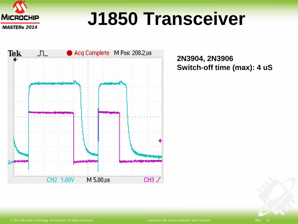
J1850 Transceiver
2N3904, 2N3906Switch-off time (max): 4 uS
© 2014 Microchip Technology Incorporated. All Rights Reserved. Interfacing with Vehicle Networks: Best Practices Slide 67
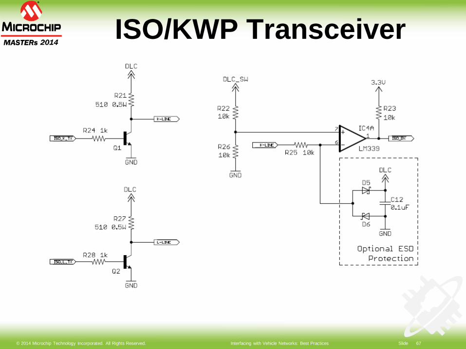
ISO/KWP Transceiver
© 2014 Microchip Technology Incorporated. All Rights Reserved. Interfacing with Vehicle Networks: Best Practices Slide 68
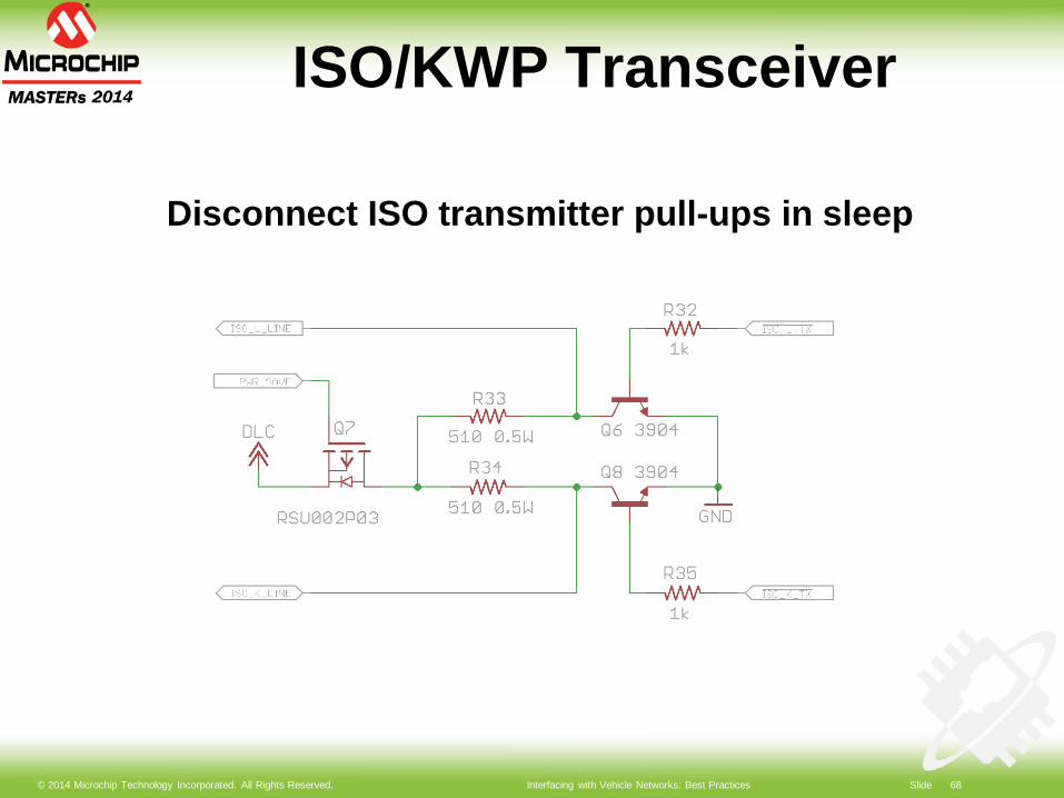
ISO/KWP Transceiver
Disconnect ISO transmitter pull-ups in sleep
© 2014 Microchip Technology Incorporated. All Rights Reserved. Interfacing with Vehicle Networks: Best Practices Slide 69
Common Pitfalls
Using slow transistors for J1850 Not switching off ISO transmitter
in sleep Not switching off or putting CAN
transceiver to sleep Powering comparators from 3V
instead of VDLC
© 2014 Microchip Technology Incorporated. All Rights Reserved. Interfacing with Vehicle Networks: Best Practices Slide 70
Lab 3:OBD Development & Testing
© 2014 Microchip Technology Incorporated. All Rights Reserved. Interfacing with Vehicle Networks: Best Practices Slide 71
Lab 3 Objectives
Create and configure a virtual ECU
Create fault sets Create custom PIDs
© 2014 Microchip Technology Incorporated. All Rights Reserved. Interfacing with Vehicle Networks: Best Practices Slide 72
Lab 3 Summary
OBD simulator is an essential tool for development/testing
It is important to simulate and test marginal cases
© 2014 Microchip Technology Incorporated. All Rights Reserved. Interfacing with Vehicle Networks: Best Practices Slide 73
Avoiding Interference
© 2014 Microchip Technology Incorporated. All Rights Reserved. Interfacing with Vehicle Networks: Best Practices Slide 74
Avoiding Interference
Symptoms Causes Solutions
© 2014 Microchip Technology Incorporated. All Rights Reserved. Interfacing with Vehicle Networks: Best Practices Slide 75
Avoiding Interference
Symptoms Tripping dashboard lights Setting off trouble codes Stalling engine Disabling functions: clock, power
windows, etc
© 2014 Microchip Technology Incorporated. All Rights Reserved. Interfacing with Vehicle Networks: Best Practices Slide 76
Avoiding Interference
Causes Hardware design flaws (e.g., hard-
wired pullups on ISO transmitter) Transmitting on the wrong protocol or
baud rate Flooding the bus with messages Long responses on J1850 PWM
© 2014 Microchip Technology Incorporated. All Rights Reserved. Interfacing with Vehicle Networks: Best Practices Slide 77
Avoiding Interference
Solutions KOEO is the best time to run protocol
detection “Listen before transmit” Remember last protocol between
power cycles Pace data requests Check RPM=0 before requesting
VIN, CALID, etc
© 2014 Microchip Technology Incorporated. All Rights Reserved. Interfacing with Vehicle Networks: Best Practices Slide 78
Summary
Today we covered: OBD and its applications Accessing and interpreting OBD data Power supply and transceiver design Using an OBD simulator Ways to avoid creating interference
on the OBD bus
© 2014 Microchip Technology Incorporated. All Rights Reserved. Interfacing with Vehicle Networks: Best Practices Slide 79
Additional Resources
SAE Standards (sae.org) J1979, J1850, J2012, J1939
ISO Standards (iso.org) ISO 9141, ISO 14230, ISO 15765
http://www.obdsol.com/articles/
© 2014 Microchip Technology Incorporated. All Rights Reserved. Interfacing with Vehicle Networks: Best Practices Slide 80
Dev Tools For This Class
STN11xx OBD development board ECUsim 2000
© 2014 Microchip Technology Incorporated. All Rights Reserved. Interfacing with Vehicle Networks: Best Practices Slide 81
LEGAL NOTICESOFTWARE: You may use Microchip software exclusively with Microchip products. Further, use of Microchip software is subject to the copyright notices, disclaimers, and any license terms accompanying such software, whether set forth at the install of each program or posted in a header or text file.
Notwithstanding the above, certain components of software offered by Microchip and 3rd parties may be covered by “open source” software licenses – which include licenses that require that the distributor make the software available in source code format. To the extent required by such open source software licenses, the terms of such license will govern.
NOTICE & DISCLAIMER: These materials and accompanying information (including, for example, any software, and references to 3rd party companies and 3rd party websites) are for informational purposes only and provided “AS IS.” Microchip assumes no responsibility for statements made by 3rd party companies, or materials or information that such 3rd parties may provide.
MICROCHIP DISCLAIMS ALL WARRANTIES, WHETHER EXPRESS, IMPLIED, OR STATUTORY, INCLUDING ANY IMPLIED WARRANTIES OF NONINFRINGEMENT, MERCHANTABILITY, AND FITNESS FOR A PARTICULAR PURPOSE. IN NO EVENT WILL MICROCHIP BE LIABLE FOR ANY DIRECT OR INDIRECT, SPECIAL, PUNITIVE, INCIDENTAL, OR CONSEQUENTIAL LOSS, DAMAGE, COST, OR EXPENSE OF ANY KIND RELATED TO THESE MATERIALS OR ACCOMPANYING INFORMATION PROVIDED TO YOU BY MICROCHIP OR OTHER THIRD PARTIES, EVEN IF MICROCHIP HAS BEEN ADVISED OF THE POSSIBLITY OF SUCH DAMAGES OR THE DAMAGES ARE FORESEEABLE.
TRADEMARKS: The Microchip name and logo, the Microchip logo, dsPIC, FlashFlex, flexPWR, JukeBlox, KEELOQ, KEELOQ logo, Kleer, LANCheck, MediaLB, MOST, MOST logo, MPLAB, OptoLyzer, PIC, PICSTART, PIC32 logo, RightTouch, SpyNIC, SST, SST Logo, SuperFlash and UNI/O are registered trademarks of Microchip Technology Incorporated in the U.S.A. and other countries.The Embedded Control Solutions Company is a registered trademark of Microchip Technology Incorporated in the U.S.A.Analog-for-the-Digital Age, BodyCom, chipKIT, chipKIT logo, CodeGuard, dsPICDEM, dsPICDEM.net, ECAN, In-Circuit Serial Programming, ICSP, Inter-Chip Connectivity, KleerNet, KleerNet logo, MiWi, MPASM, MPF, MPLAB Certified logo, MPLIB, MPLINK, mTouch, MultiTRAK, NetDetach, Omniscient Code Generation, PICDEM, PICDEM.net, PICkit, PICtail, RightTouch logo, REAL ICE, SQI, Serial Quad I/O, Total Endurance, TSHARC, USBCheck, VariSense, ViewSpan, WiperLock, Wireless DNA, and ZENA are trademarks of Microchip Technology Incorporated in the U.S.A. and other countries.SQTP is a service mark of Microchip Technology Incorporated in the U.S.A.GestIC is a registered trademarks of Microchip Technology Germany II GmbH & Co. KG, a subsidiary of Microchip Technology Inc., in other countries. All other trademarks mentioned herein are property of their respective companies.© 2014, Microchip Technology Incorporated, All Rights Reserved.

© 2014 Microchip Technology Incorporated. All Rights Reserved. Interfacing with Vehicle Networks: Best Practices Slide 82
Contact Us
1819 W Rose Garden Ln #3, Phoenix, AZ 85027(623) [email protected]