Embed Size (px)
Citation preview
1 of 14
Robotic Vehicle Design
Sensors, measurements and interfacing
Jim Keller July 2008

2 of 14
Sensor Design
• Types• Topology in system• Specifications/Considerations for Selection• Placement• Estimators
• Summary

3 of 14
Two Visual Modes of Obstacle Detection
Edge Detection/Brightness
Stereo-video

4 of 14
Sensor Types(position/motion sensing as an example)
• Position– Relative vs. absolute
• GPS provides globally referenced position• Rangefinders provide local position information with respect to the environment
– Characteristics (where do the sensors work well and where do they not, what important features must be taken into account
• GPS works well in open spaces; may not work at all in most urban areas• Rangefinders may work well unitl environment becomes cluttered or uneven
• Velocity– Groundspeed– Air or water speed for aerial or marine robots
• Typically a local measurement relative to the robot itself• Acceleration
– Almost always an absolute measure unless calibrated• Orientation (pitch/roll/compass heading)
– Heading versus track angle• Rotational rate
• Integrated packages are expensive:– Very low end ~ $1500– Precise ones > $100K
5 of 14
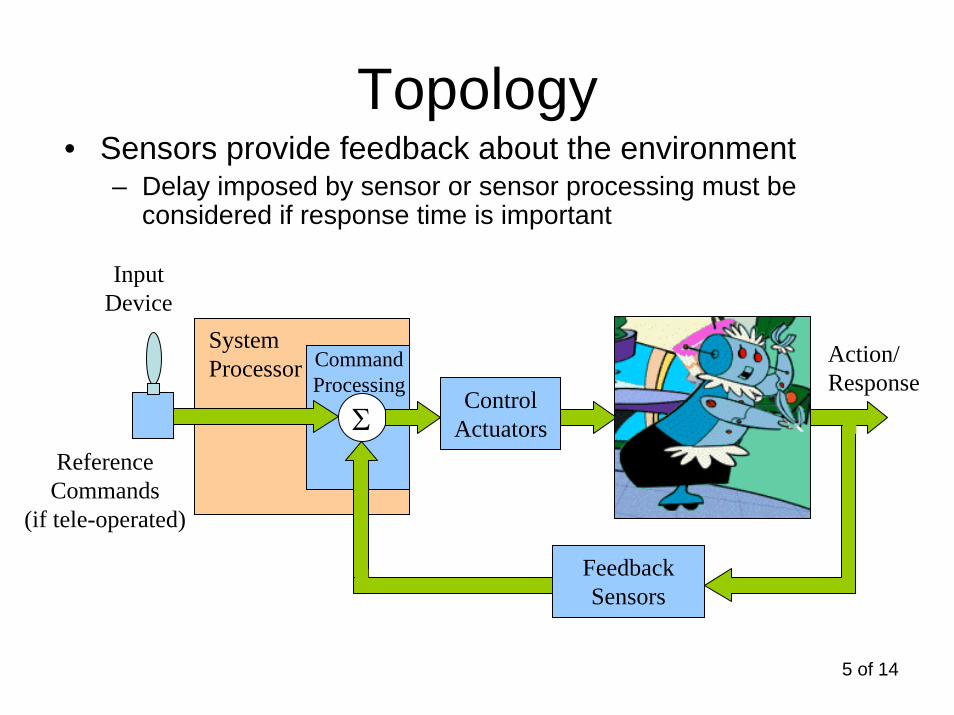
Topology• Sensors provide feedback about the environment
– Delay imposed by sensor or sensor processing must be considered if response time is important
UnaugmentedVehicle
ControlActuators
FeedbackSensors
Σ
CommandProcessing
ReferenceCommands
(if tele-operated)
SystemProcessor Action/
Response
InputDevice
6 of 14
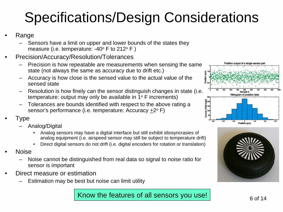
Specifications/Design Considerations• Range
– Sensors have a limit on upper and lower bounds of the states they measure (i.e. temperature: -40o F to 212o F )
• Precision/Accuracy/Resolution/Tolerances– Precision is how repeatable are measurements when sensing the same
state (not always the same as accuracy due to drift etc.)– Accuracy is how close is the sensed value to the actual value of the
sensed state– Resolution is how finely can the sensor distinguish changes in state (i.e.
temperature: output may only be available in 1o F increments)– Tolerances are bounds identified with respect to the above rating a
sensor’s performance (i.e. temperature: Accuracy +2o F)• Type
– Analog/Digital• Analog sensors may have a digital interface but still exhibit idiosyncrasies of
analog equipment (i.e. airspeed sensor may still be subject to temperature drift)• Direct digital sensors do not drift (i.e. digital encoders for rotation or translation)
• Noise– Noise cannot be distinguished from real data so signal to noise ratio for
sensor is important• Direct measure or estimation
– Estimation may be best but noise can limit utility
Know the features of all sensors you use!
7 of 14
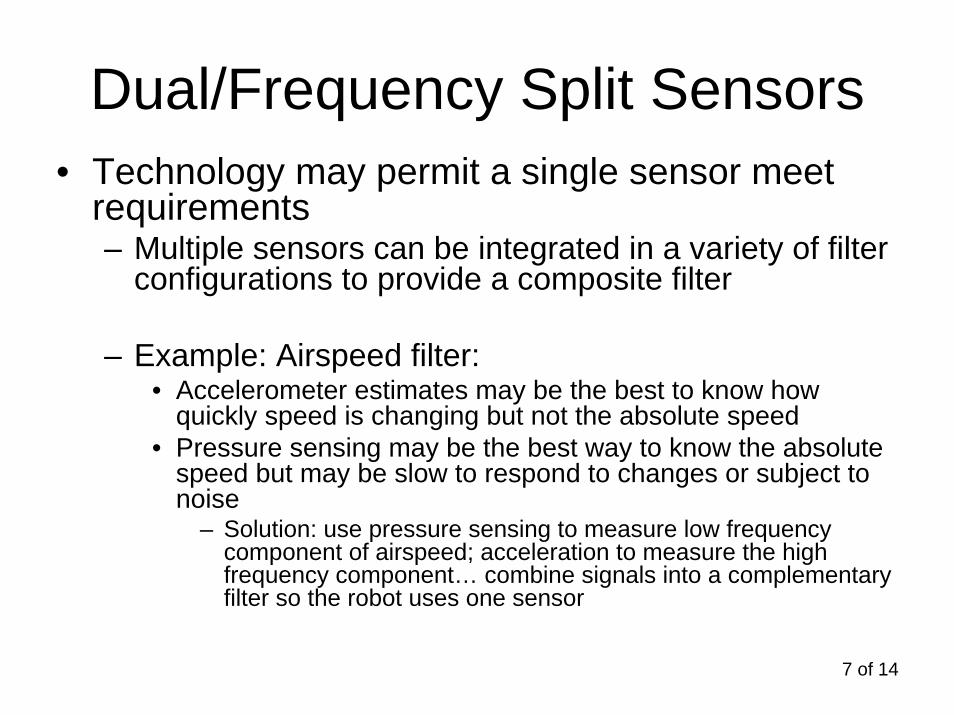
Dual/Frequency Split Sensors• Technology may permit a single sensor meet
requirements– Multiple sensors can be integrated in a variety of filter
configurations to provide a composite filter
– Example: Airspeed filter:• Accelerometer estimates may be the best to know how
quickly speed is changing but not the absolute speed• Pressure sensing may be the best way to know the absolute
speed but may be slow to respond to changes or subject to noise
– Solution: use pressure sensing to measure low frequency component of airspeed; acceleration to measure the high frequency component… combine signals into a complementary filter so the robot uses one sensor

8 of 14
Sampled Data System Contraints(input frequency cannot exceed ½ sample frequency)
• Aliasing occurs if data with a waveform higher than ½ the sample frequency is sampled
– High frequencies are “aliased” to lower frequencies– Prefiltering is required to eliminate aliasing if input cannot be guaranteed to adhere to
max frequency constraint
-1
-0.8
-0.6
-0.4
-0.2
0
0.2
0.4
0.6
0.8
1
0 0.01 0.02 0.03 0.04 0.05 0.06 0.07 0.08 0.09 0.1
Time - seconds
10 Hz signal 60 Hz signal
Data sampled at 50 Hz (T = 0.02sec)

9 of 14
Angle Parameter Definitions
Next Waypoint
PresentPosition
Last Waypoint
CrossTrackError
Along Track
Error
Groundspeed
Course
Desired
Track
North
East
Heading
TrackAngle
TrackAngleError
Bearing
Notes (GPS can provide Track relative to True North)• For ground vehicles: Heading = Track (except when skidding)• Angular references for air vehicles come in many flavors (all are typically measured from North):
• Heading - in which direction am I pointed• Track - in which direction am I moving• Bearing - which direction should I move to get from where I am to where I want to go• Course – which direction should I plan to go to get from one point of interest on my route to the next point of interest

10 of 14True North = sensor reading - declination
Magnetic Heading Sensor
A magnetic sensor is biased by declination angle based on its location• use online resources to determine (models available for download)• Philadelphia declination is: -12° 22' (W)
11 of 14
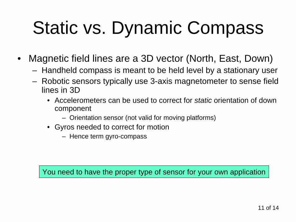
Static vs. Dynamic Compass• Magnetic field lines are a 3D vector (North, East, Down)
– Handheld compass is meant to be held level by a stationary user– Robotic sensors typically use 3-axis magnetometer to sense field
lines in 3D• Accelerometers can be used to correct for static orientation of down
component– Orientation sensor (not valid for moving platforms)
• Gyros needed to correct for motion– Hence term gyro-compass
You need to have the proper type of sensor for your own application

12 of 14
Placement• Co-location (if on-board robot)
– Always best to place sensor closest to location of importance
• Flexible structures typically require understanding of mode shapes
• Environment– Heat– Electromagnetic interference
• Cameras, GPS receivers etc. should not be next to motors etc…

13 of 14
Estimators• It may not be possible or even desirable
to directly measure– Position estimation for submarines
• A variety of state variables may be used in conjunction with a math model of the robot to estimate position based on other available measurements
– Estimators must use feedback to continuously update themselves
– Probabilistic model of system very useful to credibly integrate diverse signals into a single sensor
• Kalman filter developed in 1960’s continue to evolve today to integrate sensed data into a “best estimate”
– Time tagging of data critical when diverse sources of data are combined
– Estimation for stabilization should be used as a second resort
• Estimation introduces some delay or lag and may destabilize system to some extent

14 of 14
Summary• Select sensors required for a robot to accomplish its
task(s)– Use estimation as required
• May not be required for some applications… may be critical to others
• Understand the specifications and performance of a sensor before committing to use it in a robot– Prototype robot with variations in preliminary design to make
best sensor selection
• References: http://www.ridgesoft.com/usingsensors.htm