Embed Size (px)
Citation preview
Interactive Video Overlay for the CollaBoard
Patrick Ponti
Semester Term Thesis
2006
Supervisors: Prof. Dr. Markus Gross Dr. Stephan Wuermlin
Dipl. Ing. Martin Kuechler Dipl. Ing. Daniel Cotting
Computer Graphics Laboratory Department of Computer Science
ETH Zurich

ii

iii
Abstract
In this semester thesis, we want to replace a hardware chroma keyer by a DirectShow-based software video overlay. A conceptual design of a filter has first been provided, that identified the best way to access the graphics streams at system level. Then a first draft of the C++ code has been implemented, with the attention more addressed to the concrete results and not to the performance. In a second analysis, the performance of the video overlay has been optimized by porting the overlay algorithm to the GPU. The last purpose of the project was to give to our solution the possibility to get inputs over the network. In order to achieve this objective, the ConferenceXP application has been chosen. This open source software has been modified in order to integrate our key-chroma functionality in a standard conferencing system.

iv
v
Contents
Introduction 1 About Collaboard 1 About the report 2
DirectShow 3
Introduction 3 COM Objects 4 What is a DirectShow filter? 5 What is a DirectShow graph? 5 Basic steps for creating a COM object 6
Concepts 7
Key-Chroma 7 Video Mixing Renderer 9 9 ConferenceXP 10
Implementation 11
DirectShow filter graph 11 Implementation of the custom Compositor 13 Integration of the key-chroma application in ConferenceXP 16
Conclusions 19 Bibliography 21

vi

1
1 Introduction
About Collaboard
Within the blue c-II project [1], the Innovation Center Virtual Reality (ICVR) [2] develops and implements a setup called CollaBoard. The setup features standard electronic whiteboard functionality. In addition, a video from the scene in front of the interactive workspace is acquired. In stand-alone operation, the video allows to document the constitution process of the information on the electronic whiteboard. If two CollaBoards are interconnected via a network, the displayed shared electronic content is enriched with a video stream from the remote station. This allows transferring meta information in addition to the regular shared content. Both, the video and the shared content, are separately acquired and transferred, but are overlaid to be displayed on the interaction space. This guarantees that the content of the interaction space remains editable. Before the video of the users can be overlaid atop the shard electronic content, the users must be subtracted from the dynamic projected background. To reduce the dynamic range of the projected background, we are blanking the projection to the camera by using twisted linear polarization filters in front of the projector and camera lens, and a polarization
2
preserving projection screen. However, this projection blanking alone is not sufficient for direct subsequent chroma keying for the video overlay. We therefore perform a foreground/ background-segmentation before the video stream is routed to the chroma keyer.
About the report
This report is structured in the following way. In chapter 2, the DirectShow technology is analyzed. We start with a general overview of the technology and we then describe more in details its main components: COM objects, filters and filter graphs. Chapter 3 is an enumeration of the key concepts used in the project. We provide an introduction for the Key-Chroma, the Video Mixing Renderer 9 and the ConferenceXP concepts. In chapter 4 we describe the implementation process, clearly diving it in its three main phases: the analysis process, the implementation of the chroma keying feature and the integration of the prototype in ConferenceXP. Chapter 5 gives some conclusions, describing the actual state of the prototype.
3
2 DirectShow
Introduction
DirectShow [3] is a media streaming technology; it is part of the well-known Microsoft’s DirectX [4] suite. DirectShow contains all of the components for audio/video capture and playback for a very large number of formats. As an example, the Windows Media Player is an application written using DirectShow. Considering a live streaming application, it is possible to distinct four main components: audio/video capture devices, encoders, decoders, and renderers. The capture devices basically get the inputs that will then be transformed by encoders and decoders. These transformations are then made visible thanks to the renderers, which ouput the result of the computation. These four basic components can be used simply by getting access to the DirectShow Application Programming Interface (API). Thanks to this API, the development of DirectShow components that can interoperate with other already existing components is considerably simplified.

4
COM Objects
The DirectShow technology is based on the Component Object Model (COM) [5]. Each DirectShow object, such as an encoder, a decoder, a renderer or a capture device is a COM object. COM objects base on a model of reusable components. As programs became more and more complex, the need of programmers of reusing already implemented components occurred even more. This means to avoid rewriting many and many lines of code, according to the basic object oriented concepts of modularity and reusability. Trying to satisfy this need, Microsoft introduced COM as a way of using (and re-using) components in the Windows operating system. In order to use a COM object, it has first to be loaded by searching it within all the ones registered in the operating system’s record. If it exists, the operating system loads it. The difference of COM objects with respect to the standard methodology of reusing code libraries is that when using COM, the compiler only needs to know the interface of the object. This way, the object is created and accessed at run time, without recompiling any lines of code, as happens in the case of the re-usage of code libraries. COM also has other features such as the ability for objects to be distributed, and to provide security access control. A COM object provides an interface, which defines how the programmer can interact with the object itself. The interface simply lists all the callable methods that are implemented by the object and appears as the unique way to interact with the object, since it is not possible to get a direct access to object’s data. From the point of view of the implementation, it is important to mention some particular characteristics that every COM object has to satisfy. All COM objects implement the IUnknown interface, which defines the basic functionalitiy needed for a COM object to exist. IUnknown containts three methods: QueryInterface(), AddRef() and Release(). The first method, QueryInterface(), allows the programmer to check for other interfaces of the objects, since a COM object can provide several interfaces. The remaining two methods, AddRef() and Release(), are required because of the way COM handles creation and destruction of COM objects. Actually, it is possible that a COM object is used at the same time by several clients. When one of them ends the usage of the object, it cannot delete it because the other clients are still using the object itself. Instead, the client calls the Release() method which decrements an internal object reference count. When the object count equals zero, the object itself knows that no one is currently using it and it can delete itself. The AddRef() method, instead, increases the count of the object by one and is performed when the object is first referenced by a client. A COM object normally defines one or more interfaces, already existing or custom implemented, other than the IUnknown one. This enables to represent common functionalities for similar, but distinct, COM objects.
5
What is a DirectShow filter?
A media stream is formed by many components combined together. Each one of this component can be implemented as a DirectShow filter. The implementation of such a filter requires one basic rule: every DirectShow filter has to be designed using a common structure template. This template contains information such as the filter name, the number of pins (the input and output “doors” of the filter) and the identification number (ID) of the filter itself. There are three main types of filters: source filters, transform filters and render filters. The first ones are the genesis of the media stream and as an example we can mention files or internet streams. The transform filters are the ones that makes some kind of computation on the media stream. They receive a media sample, transform it and send it along to the next filter. The last category of filters, the render ones, are located at the end of the filters chain and provides a way to render video and audio outputs. All the filters are based on the COM model and implement one or more COM interfaces, depending on the type of the filter itself. At least one input or output pin is contained by each kind of filter and this pin represents the way on which the communication between two different filters is built. The concept of component has been introduced in the filter architecture for one main reason: using pre-existing components. This way it is possible to construct a very complex video/audio streaming software in a reasonable amount of time. If we want to implement a particular feature for our own streaming software it is enough to implement it as a DirectShow filter that can be then connected to the pre-existing filters, in order to have a customized streaming software without too much work.
What is a DirectShow graph?
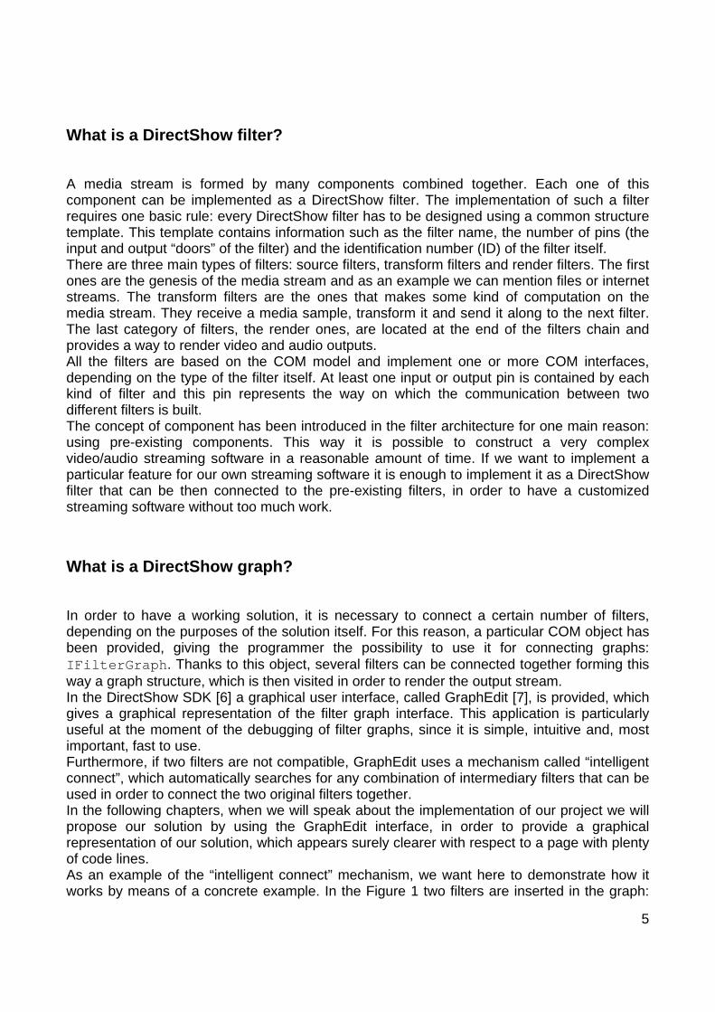
In order to have a working solution, it is necessary to connect a certain number of filters, depending on the purposes of the solution itself. For this reason, a particular COM object has been provided, giving the programmer the possibility to use it for connecting graphs: IFilterGraph. Thanks to this object, several filters can be connected together forming this way a graph structure, which is then visited in order to render the output stream. In the DirectShow SDK [6] a graphical user interface, called GraphEdit [7], is provided, which gives a graphical representation of the filter graph interface. This application is particularly useful at the moment of the debugging of filter graphs, since it is simple, intuitive and, most important, fast to use. Furthermore, if two filters are not compatible, GraphEdit uses a mechanism called “intelligent connect”, which automatically searches for any combination of intermediary filters that can be used in order to connect the two original filters together. In the following chapters, when we will speak about the implementation of our project we will propose our solution by using the GraphEdit interface, in order to provide a graphical representation of our solution, which appears surely clearer with respect to a page with plenty of code lines. As an example of the “intelligent connect” mechanism, we want here to demonstrate how it works by means of a concrete example. In the Figure 1 two filters are inserted in the graph:
6
the PushSource Desktop filter (a filter that grabs the desktop of the machine with a given frequency) and a Video Renderer Filter. Connecting the output pin of the PushSource Desktop filter and the input of the Video Renderer Filter needs the participation of the “intelligent connect” mechanism, since the two pins are not compatible. GraphEdit automatically inserts the Color Space Converter filter in between the two original ones in order to make compatible the output stream of the first filter with the input pin of the renderer filter, as shown in Figure 2.
Figure 1 Two incompatibles filters.
Figure 2“Intelligent connect” automatically inserts the Color Space Converter filter.
Pressing the Play button in GraphEdit a video display window pops up and the captured desktop starts to be played.
Basic steps for creating a COM object
A COM object can be called up and executed in a Windows Environment. In order to make that, the COM object has first to be compiled and registered by the operating system. For this purpose to be achieved, the COM object has to be identified by a COM GUID. The GUID is an identification number generated by a Windows utility program called uuidgen.exe, which basically contains two pieces of information: the ID of the filter itself and the ID of the category it belongs to. Every COM object has a different GUID, which provides the operating system with a unique identifier, needed for the recognition of the object itself. Creating a COM object can be significantly simplified by using the Microsoft Active Template Library (ATL) [8] technology. ATL is a set of software routines from Microsoft that provide the basic framework for creating ActiveX and COM objects. Other than basic COM classes, ATL provides also implementations for some of the common COM interfaces, including IUnknown, IDispatch and IClassFactory. But we do not want here to go into the details of these interfaces. Once the COM object has been registered, it can then be used simply by searching its GUID among the ones registered in the operating system’s record.
7
3 Concepts
Key-Chroma
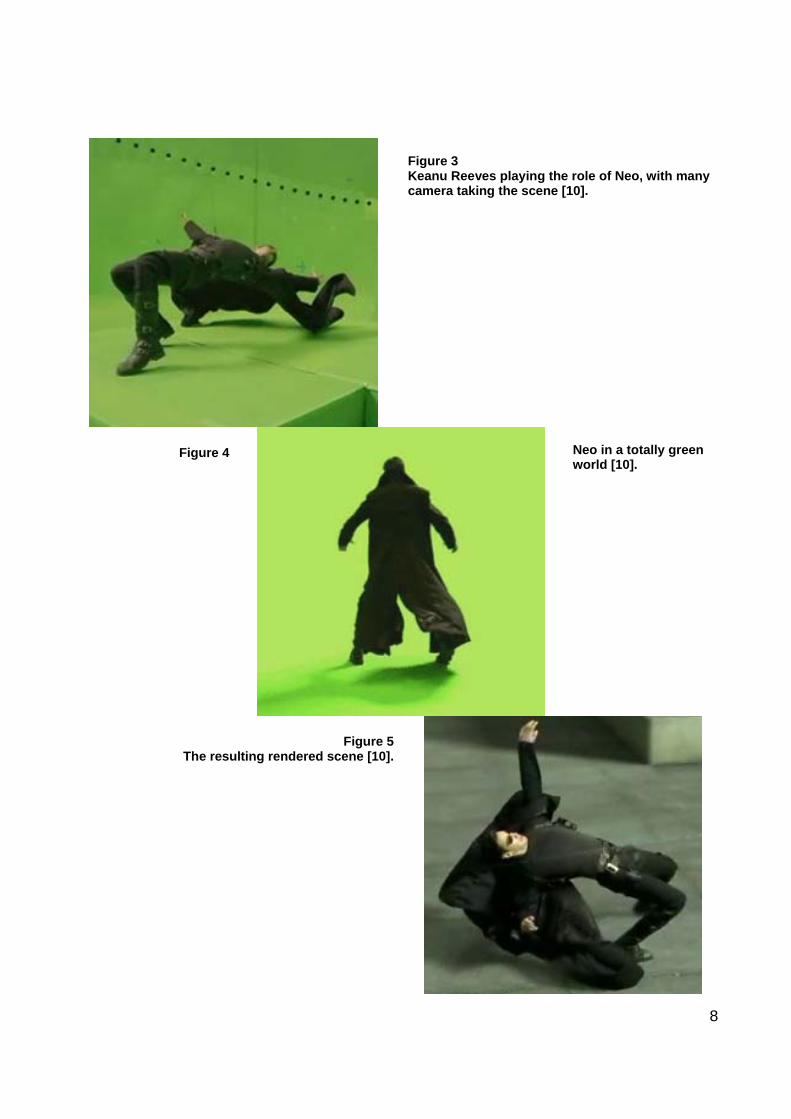
The Key-Chroma technique is also known as constant color matting. Constant color matting is widely used within the television and movie industries and basically consists of filming an object or an actor in front of a uniformly colored screen, which will be then digitally replaced by a different background. The screen’s color is usually blue, green or red. Using such a uniformed colored screen significantly simplifies the removal of the background, since, from the theoretical point of view, the computation is reduced to the deletion of a single color from the scene. Using this technique, scenes that would be impossible to film with an actor and scenes which would be too dangerous to be played are now possible. As an example, this technique has been widely use in the Matrix [9] movie, where the main character, in the famous “bullet-time” action, played within a green room. Figures 3, 4 and 5 show the actor Keanu Reeves playing the role of the main movie’s character Neo.
8
Figure 3 Keanu Reeves playing the role of Neo, with many camera taking the scene [10].
Figure 4
Neo in a totally green world [10].
Figure 5The resulting rendered scene [10].

9
In our application the color chosen for the background screen is green. It is the result of a segmentation algorithm, in which the subject of the camera has been transported in front of a completely green screen.
Video Mixing Renderer 9
The Video Mixing Renderer 9 (VMR9) [11] is the latest technology in Video Rendering. VMR9 is completely based on the DirectX 9 3D capabilties (Direct3D [12]) and offers advanced video rendering capabilities on all platforms supported by DirectX [4]. In order to maintain compatibility with older systems, the VMR9 is not the default renderer on any system: the VMR7 is still used as default renderer. Because of this, the VMR9 has to be explicitly added to the filter graph and configured before connecting any of its input pins. It also uses its own set of interfaces and structures which are not always identical to the corresponding data types used with the VMR7. VMR9 supports three distinct rendering modes:
- VMR9: Windowed This is the basic rendering mode and it is usually used for backward compatibility. It does not provide access to Frame Capturing (the capability to take screen images in real-time and store them in the memory).
- VMR9: Windowless This rendering mode is slightly more advanced than the Windowed mode and is the best mode in which conducting screen captures.
- VMR9: Renderless This is the most complex rendering mode. It can work in Direct3D Exclusive mode which means that no background applications are allowed to have access to the video hardware. Under Direct3D Exclusive mode less CPU is required to play video, but the drawback is that in this mode the computer is wholly dedicated to video playback and the user will not be able to perform any other tasks.
The VMR9 has been chosen as the Video Renderer for our application basically for performance reasons. Indeed, at the very beginning of the project, when the analysis phase of the requirements of the projects was in its lively execution, the arisen discussion was about the implementation shape of our project: as a new filter or as customization of the VMR9? We eventually decided for the second alternative, since the VMR9 already provided us with a high performance streams compositing mechanism. This way, we did not matter about the composition itself, but only about the key-chroma algorithm. We will analyze later on, how this algorithm has been really implemented.
10
ConferenceXP
ConferenceXP [13] is one of the research projects of Microsoft Research [14]. In a few words, it can be described as an interactive and collaborative environment which basically connects people over a network. ConferenceXP enables people to see and hear other participants, to collaborate on a virtual whiteboard or on a presentation and to send messages to each other, by providing a high-quality videoconferencing system. The ConferenceXP is open source and hence freely available and developable. This way, we could use and modify the already implemented features of ConferenceXP in order to achieve our objectives. As we will see later more in details, we were especially attracted by one of the several capabilities of ConferenceXP: its video conferencing system. We further developed it in order to support the key-chroma algorithm that we implemented in the first part of the project.
11
4 Implementation
DirectShow filter graph
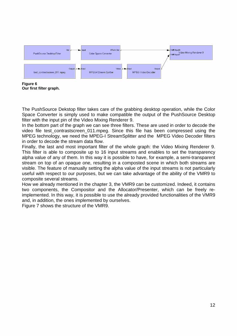
We will talk in the following about the implementation of the central part of out project. First of all, we built a DirectShow filter graph, which satisfies our three main desires: the first one concerns the “grabbing” operation of the desktop of the machine on which our application is executing, the second one is to provide a video stream as a second input and the last one is about the compositing of the two previous results. In the first phase of the development we used as video stream an MPEG file, which contains a person in front of a green background. In a second phase this video will be substituted by the real input of our application, but we will speak more in details about this later on. For the moment, we want to explain the main concepts of our solution by using this MPEG video. Figure 6 shows our filter graph.
12
Figure 6 Our first filter graph. The PushSource Dekstop filter takes care of the grabbing desktop operation, while the Color Space Converter is simply used to make compatible the output of the PushSource Desktop filter with the input pin of the Video Mixing Renderer 9. In the bottom part of the graph we can see three filters. These are used in order to decode the video file test_contrastscreen_011.mpeg. Since this file has been compressed using the MPEG technology, we need the MPEG-I StreamSplitter and the MPEG Video Decoder filters in order to decode the stream data flow. Finally, the last and most important filter of the whole graph: the Video Mixing Renderer 9. This filter is able to composite up to 16 input streams and enables to set the transparency alpha value of any of them. In this way it is possible to have, for example, a semi-transparent stream on top of an opaque one, resulting in a composted scene in which both streams are visible. The feature of manually setting the alpha value of the input streams is not particularly useful with respect to our purposes, but we can take advantage of the ability of the VMR9 to composite several streams. How we already mentioned in the chapter 3, the VMR9 can be customized. Indeed, it contains two components, the Compositor and the Allocator/Presenter, which can be freely re-implemented. In this way, it is possible to use the already provided functionalities of the VMR9 and, in addition, the ones implemented by ourselves. Figure 7 shows the structure of the VMR9.

13
Figure 7 The VMR structure. In the next section, we will speak about the provided implementation of the Compositor. Mainly, the Compositor is the VMR9 component that takes care of the composition of the input streams. Beside the standard functionalities provided by the VMR9, with our custom Compositor we added the key-chroma functionality to the VMR9. This way, the green background of the video input is substituted by the desktop coming from the PushSource Desktop filter. The implementation and a more detailed explanation follow in the next section.
Implementation of the custom Compositor
As said in the previous section, in order to integrate our key-chroma functionality within the VMR9 we provided a custom implementation of the Compositor component. The Compositor’s code bases itself on two interfaces: IUnknown, which has to be implemented by each COM object, and IVMRImageCompositor9, which lists the methods that have to be implemented by our custom Compositor. Implementing the IUnknown interface makes sure that our Compositor follows the COM implementation rules and that therefore it is considered as a COM object as well. Of the four methods declared in the IVMRImageCompositor9 interface, we are most interested in the CompositeImage() one. Within this method, the composition of the input streams of the VMR9 is performed. In order to analyze more in details the compositing of the input streams, it is necessary first to remember that our VMR9 takes as the first input a stream composed of a series of desktop
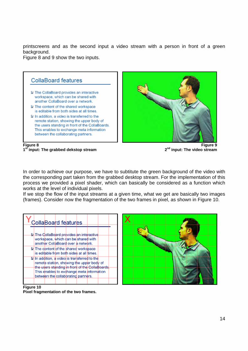
14
printscreens and as the second input a video stream with a person in front of a green background. Figure 8 and 9 show the two inputs.
Figure 8 1st input: The grabbed dekstop stream
Figure 92nd input: The video stream
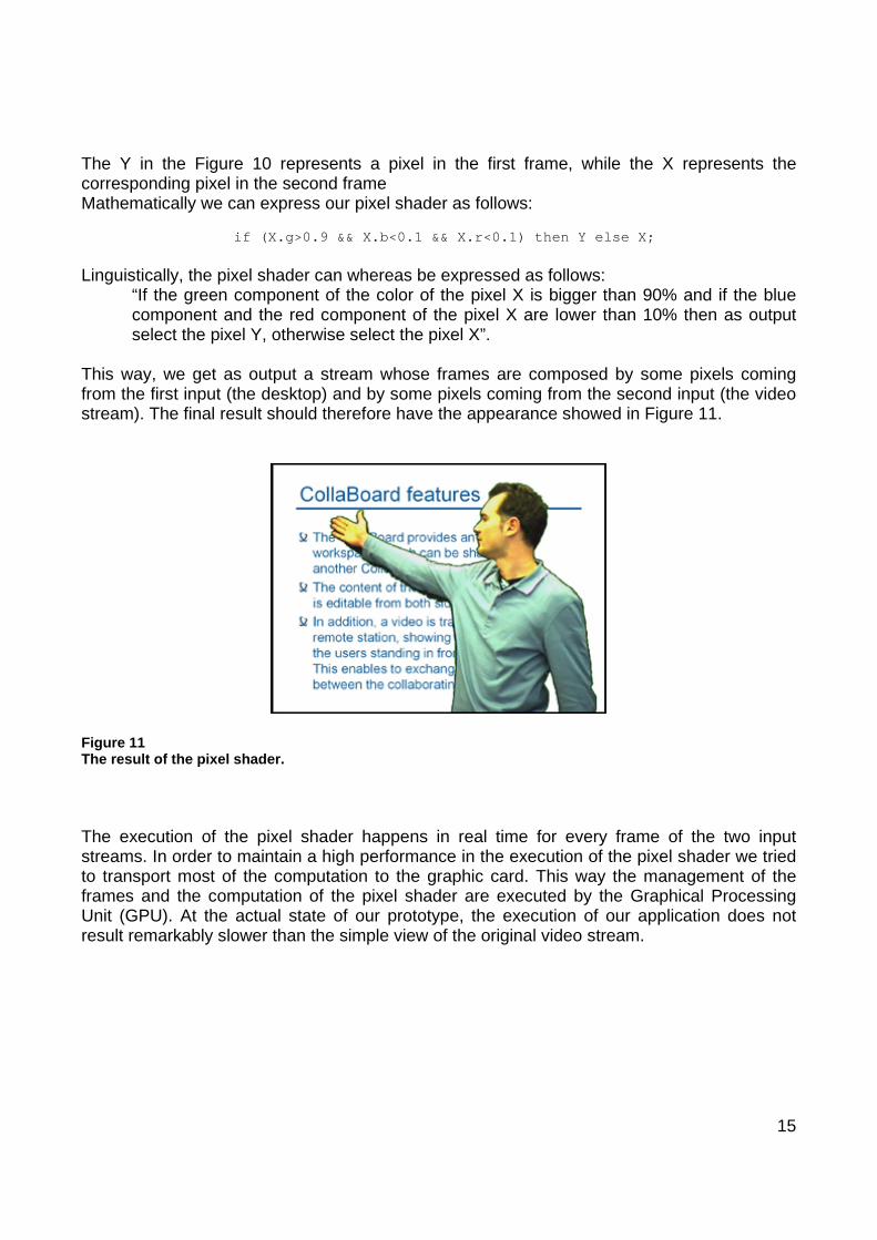
In order to achieve our purpose, we have to subtitute the green background of the video with the corresponding part taken from the grabbed desktop stream. For the implementation of this process we provided a pixel shader, which can basically be considered as a function which works at the level of individual pixels. If we stop the flow of the input streams at a given time, what we get are basically two images (frames). Consider now the fragmentation of the two frames in pixel, as shown in Figure 10.
Figure 10 Pixel fragmentation of the two frames.
15
The Y in the Figure 10 represents a pixel in the first frame, while the X represents the corresponding pixel in the second frame Mathematically we can express our pixel shader as follows: if (X.g>0.9 && X.b<0.1 && X.r<0.1) then Y else X; Linguistically, the pixel shader can whereas be expressed as follows:
“If the green component of the color of the pixel X is bigger than 90% and if the blue component and the red component of the pixel X are lower than 10% then as output select the pixel Y, otherwise select the pixel X”.
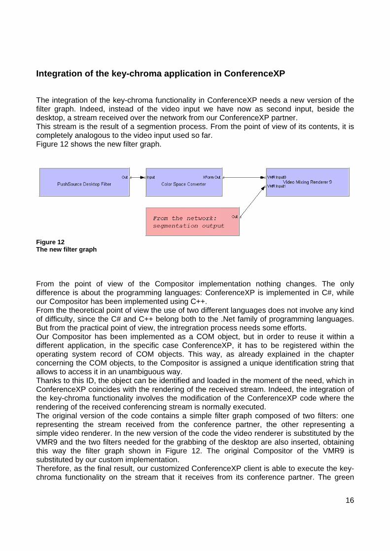
This way, we get as output a stream whose frames are composed by some pixels coming from the first input (the desktop) and by some pixels coming from the second input (the video stream). The final result should therefore have the appearance showed in Figure 11.
Figure 11 The result of the pixel shader. The execution of the pixel shader happens in real time for every frame of the two input streams. In order to maintain a high performance in the execution of the pixel shader we tried to transport most of the computation to the graphic card. This way the management of the frames and the computation of the pixel shader are executed by the Graphical Processing Unit (GPU). At the actual state of our prototype, the execution of our application does not result remarkably slower than the simple view of the original video stream.
16
Integration of the key-chroma application in ConferenceXP
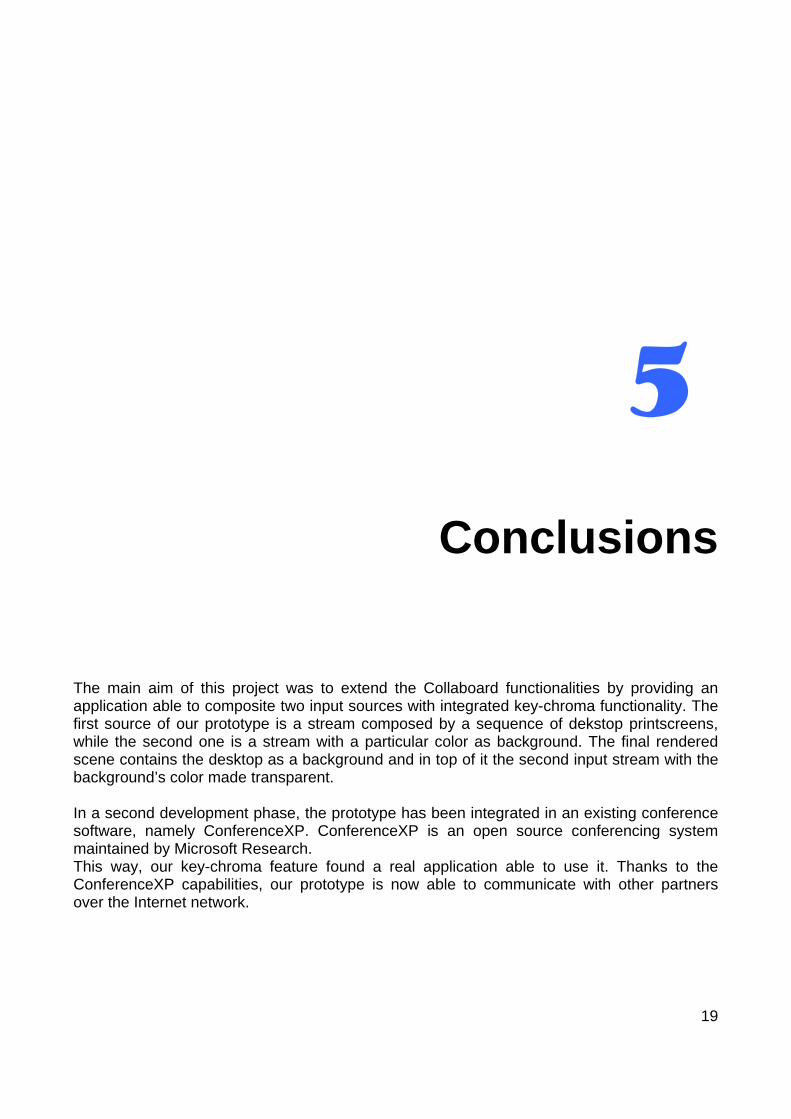
The integration of the key-chroma functionality in ConferenceXP needs a new version of the filter graph. Indeed, instead of the video input we have now as second input, beside the desktop, a stream received over the network from our ConferenceXP partner. This stream is the result of a segmention process. From the point of view of its contents, it is completely analogous to the video input used so far. Figure 12 shows the new filter graph.
Figure 12 The new filter graph From the point of view of the Compositor implementation nothing changes. The only difference is about the programming languages: ConferenceXP is implemented in C#, while our Compositor has been implemented using C++. From the theoretical point of view the use of two different languages does not involve any kind of difficulty, since the C# and C++ belong both to the .Net family of programming languages. But from the practical point of view, the intregration process needs some efforts. Our Compositor has been implemented as a COM object, but in order to reuse it within a different application, in the specific case ConferenceXP, it has to be registered within the operating system record of COM objects. This way, as already explained in the chapter concerning the COM objects, to the Compositor is assigned a unique identification string that allows to access it in an unambiguous way. Thanks to this ID, the object can be identified and loaded in the moment of the need, which in ConferenceXP coincides with the rendering of the received stream. Indeed, the integration of the key-chroma functionality involves the modification of the ConferenceXP code where the rendering of the received conferencing stream is normally executed. The original version of the code contains a simple filter graph composed of two filters: one representing the stream received from the conference partner, the other representing a simple video renderer. In the new version of the code the video renderer is substituted by the VMR9 and the two filters needed for the grabbing of the desktop are also inserted, obtaining this way the filter graph shown in Figure 12. The original Compositor of the VMR9 is substituted by our custom implementation. Therefore, as the final result, our customized ConferenceXP client is able to execute the key-chroma functionality on the stream that it receives from its conference partner. The green

17
background of the incoming stream is substitued in real time by the desktop of the machine. The resulting output stream is shown in Figure 11.

18
19
5 Conclusions
The main aim of this project was to extend the Collaboard functionalities by providing an application able to composite two input sources with integrated key-chroma functionality. The first source of our prototype is a stream composed by a sequence of dekstop printscreens, while the second one is a stream with a particular color as background. The final rendered scene contains the desktop as a background and in top of it the second input stream with the background’s color made transparent. In a second development phase, the prototype has been integrated in an existing conference software, namely ConferenceXP. ConferenceXP is an open source conferencing system maintained by Microsoft Research. This way, our key-chroma feature found a real application able to use it. Thanks to the ConferenceXP capabilities, our prototype is now able to communicate with other partners over the Internet network.

20
21
Bibliography
[1] blue c-II project, http://blue-c.ethz.ch/ [2] Innovation Center Virtual Reality, www.inspire.ethz.ch [3] Microsoft DirectShow,
http://msdn.microsoft.com/windowsmedia/techart/directshow/default.aspx [4] Microsoft DirectX, www.microsoft.com/directx/ [5] The Component Object Model (COM), www.microsoft.com/com/ [6] The DirectShow SDK,
http://msdn.microsoft.com/windowsmedia/techart/directshow/default.aspx [7] GraphEdit,
http://msdn.microsoft.com/library/default.asp?url=/library/en-us/directshow/htm/usinggraphedit.asp
[8] Microsoft Active Template Library (ATL),
http://msdn.microsoft.com/library/default.asp?url=/library/en-us/vcmfc98/html/atl.asp [9] The Matrix Movie, http://whatisthematrix.warnerbros.com/ [10] Images of the Matrix Movie, http://whatisthematrix.warnerbros.com/ [11] The Video Mixing Renderer 9,
http://msdn.microsoft.com/library/default.asp?url=/library/en-us/directshow/htm/videomixingrendererfilter9.asp
22
[12] Direct3D, http://www.shaderx.com/direct3d.net/ [13] The ConferenceXP project, www.conferencexp.net [14] Microsoft Research, http://research.microsoft.com/


![Interactive Video Tips: Crowdsourcing video content - 6 tips for creating successful Interactive Videos [Week 7]](https://img.pdfslide.us/doc/110x75/53fa1e728d7f72b82e8b4d73/interactive-video-tips-crowdsourcing-video-content-6-tips-for-creating-successful-interactive-videos-week-7.jpg)


![Interactive Video Tips: Using call-to-action buttons in Interactive Video [Week 4]](https://img.pdfslide.us/doc/110x75/554d12a0b4c905805d8b50b6/interactive-video-tips-using-call-to-action-buttons-in-interactive-video-week-4.jpg)


![Interactive Video Tips: What is the ideal length of an Interactive Video? [Week 2]](https://img.pdfslide.us/doc/110x75/554d11e8b4c905d4568b51cc/interactive-video-tips-what-is-the-ideal-length-of-an-interactive-video-week-2.jpg)


![Interactive Video Tips: How to optimize Interactive Video for mobile devices [Week 5]](https://img.pdfslide.us/doc/110x75/554d129db4c905805d8b50b4/interactive-video-tips-how-to-optimize-interactive-video-for-mobile-devices-week-5.jpg)