Embed Size (px)
Citation preview
S15
S14
S12
CH1 VOL
P83412 REV ( )
EARTHGND
REV:SN:
TB2
R46
RV1
C33
D13
D12
R59R60
R57R58
R55R56
R53R54
R51R52
R49R50
R47R48
R62
U17
U13
C48
C41
C40
C39
C38
C36
C35
C34
TB3
RV8
R72
RV9
RV10
R69
R68Q1
R73
Q2
RV5
R64 R63D11RV7
RV6
RV3
RV4
RV2
J5
J6
R65
U14
C43
C44
R71
U16C50
C49C47
U15
R66
R67
R70
C46
C45
U11
C42
C32
U12
D10
R41
R40
C30
C31
C29C28
R43
R44 R42
U10
R61
C37
R39
R38
C9
E1
F1
K1
R45
D3
J3
TB1
J2
C10 D2 D1
C8 R9 R2R5R7 R1C4 C2C7 C5
R32
K2
J1
D4
U8
C23
U7C27
C24C25
R34R35
D9
L2
U9
C26
L1
C21
D8R33
C22
J4
R36R37
D5
D7
D6
R28
R23
R10
R19 R13
R21R22 R14R17C17 C14 C12
U5
U6
C20
C19R26 R25 R30
R31 R29
R24C18
R16U3U4
C16R20 R18 C15
R8U1 R6C6
U2C11R15 C13 R11R12
R3R4 C3 C1
R27
+
+
+
+
+
S8
12
34
ON
12
34
ON
J1
MICROPHONE
TB5
E1SW5
SW4
TB3
TB2
TB1SW1 SW2 SW3
K1 K2
K3
F1
F2
X1 X2
J2P1
C16
D1 D2
U1
U2
U3 U4
U5
U6
U8 U9
U10
+-
+-+-
+-
+-+-
T1
+-
+-
+-
SAFEPATH P83167 REV B
AMBER GREEN
TRB AUD
TRB COMTRB NOTRB NCALARM COMALARM NOALARM NC
DV POWER
DV STATUS
CH PLAY
LINE OUT
LINE IN
RM AUDIO
RM TXDRM RXD
RM POWER
+
+-
-
TONE SEL321CND FLT ENB
RM ENABLESYNCDV ENABLELAMP TEST
AUDIO
STROBE
SPK AMP
24V
ALL CALL
+-
+-GROUND
FAULTADJUST
R53
SAFEPATH® Installation, Testing, Operation,
and Maintenance Manual
FOR
Single Circuit SAFEPATH® Systems
SCSP-4RP (108951) SCSP-8RP (108952) SCSP-15SP (108969)
273 Branchport Avenue, Long Branch, NJ 07740-6899 Ph: (732) 222-6880 Fax: (732) 222-2588 Toll Free 800-631-2148 Web Site: www.wheelockinc.com E-Mail: [email protected]
A83637 Revision B

Intentionally Blank
iii
Typographical Notation Conventions Thank you for using our products. Use this product according to this instruction manual. Please keep this instruction manual for future reference. ANY MATERIAL EXTRAPOLATED FROM THIS DOCUMENT OR FROM WHEELOCK MANUALS OR OTHER DOCUMENTS DESCRIBING THE PRODUCT FOR USE IN PROMOTIONAL OR ADVERTISING CLAIMS, OR FOR ANY OTHER USE, INCLUDING DESCRIPTION OF THE PRODUCT'S APPLICATION, OPERATION, INSTALLATION AND TESTING IS USED AT THE SOLE RISK OF THE USER AND WHEELOCK WILL NOT HAVE ANY LIABILITY FOR SUCH USE. Certain information contained in this manual has been extracted from the NFPA 72 Manual (1999 Edition) and the Life Safety Code 101� Manual (2000 Edition).
Notation Conventions This manual uses the following notation conventions:
WARNING: INDICATES A POTENTIALLY HAZARDOUS SITUATION THAT, IF NOT AVOIDED, COULD RESULT IN PROPERTY DAMAGE AND SERIOUS PERSONAL INJURY OR DEATH TO YOU AND OR OTHERS.
CAUTION: Indicates a potentially hazardous situation that, if not avoided, could result in minor or moderate injury. It may also be used to alert against unsafe practices.
P83636 Rev. G March 2003 Copyright 2003 Wheelock, Inc. All rights reserved.

iv
Intentionally Blank
v
TABLE OF CONTENTS
Typographical Notation Conventions����������������������� iii
Table of Contents�������������������������������. v
Table of Figures�������������������������������� vii
Table of Tables��������������������������������. ix
Chapter 1 � Safety Precautions�������������������������. 1-1
Section 1-1 � Read This Manual����������������������. 1-1 Section 1-2 � Operational Safety���������������������� 1-1 Section 1-3 � Compliance with Applicable Codes, Regulations, Laws, Standards, And Guidelines�����������������������. 1-2 Section 1-4 � Property Insurance Recommendation�������������.. 1-2 Section 1-5 � Audio Output Considerations�����������������. 1-3 Section 1-6 � RF Interference����������������������� 1-3 Section 1-7 � General��������������������������.. 1-3
Chapter 2 � Overview and Features�����������������������. 2-1
Section 2-1 - Description�������������������������. 2-1 Section 2-2 � Enclosure and Configuration�����������������.. 2-2 Section 2-3 � Nominal Electrical Data�������������������.. 2-2 Section 2-4 � Module Configurations�������������������� 2-3 Section 2-5 � Single Circuit SAFEPATH® Panel Basic Configuration��.����. 2-3 Section 2-6 � Remote Microphone Station (RMS-2) (Optional)��������� 2-3 Section 2-7 � Operation Modes����������������������. 2-4 Section 2-8 � Glossary of Terms���������������������.. 2-4
Chapter 3 � Installation and Setup������������������������ 3-1
Section 3-1 � Introduction������������������������� 3-1 Section 3-2 � Fire Alarm Control Panel Interface Wiring Applications������. 3-1 Section 3-3 � General Installation Instructions���������������� 3-2 Section 3-4 � Prepare a System Wiring Diagram��������������� 3-4 Section 3-5 � Mounting�������������������������� 3-13 Section 3-6 - System Checkout����������������������. 3-15 Section 3-7 � Ground Fault Detection Sensitivity Adjustment���������.. 3-18 Section 3-8 � Battery Care and Backup Battery Calculations���������... 3-19
Chapter 4 � Operation����������������������������� 4-1
Section 4-1 � Introduction������������������������.. 4-1 Section 4-2 � Operator�s Console���������������������. 4-1 Section 4-3 � Supervision������������������������.. 4-1 Section 4-4 � Actions That Initiate Alarms�����������������.. 4-2
Chapter 5 � Operational Procedures����������������������.. 5-1
Section 5-1 � Operator Instructions��������������������� 5-1
vi
Section 5-2 � To Make Live Announcements����������������.. 5-1 Section 5-3 � To Sound Evacuation Tone������������������ 5-1 Section 5-4 � To Reset Visual Appliances������������������ 5-2 Section 5-5 � To Acknowledge a Trouble Condition�������������.. 5-2
Chapter 6 � Periodic Testing and Maintenance������������������. 6-1
Section 6-1 � Periodic Testing����������������������� 6-1 Section 6-2 � Qualified Personnel..��������������������� 6-1 Section 6-3 � Miscellaneous Hardware Testing ���������������. 6-1
Chapter 7 � Troubleshooting��������������������������. 7-1
Section 7-1 � Troubleshooting����������������������� 7-1
Section 7-2 - SAFEPATH® Module Replacement Procedure���������.. 7-11
Section 7-3 � Single Circuit SAFEPATH® Module Wiring Diagram����..��.. 7-12
Chapter 8 � Technical Data��������������������������.. 8-1
Section 8-1 � Mechanical������������������������.. 8-1 Section 8-2 � Environmental�����������������������. 8-1 Section 8-3 � Electrical�������������������������.. 8-1
Chapter 9 � Module Descriptions������������������������ 9-1
Section 9-1 � Introduction������������������������. 9-1
Section 9-2 Single Circuit SAFEPATH® Motherboard (SCMB)����.����. 9-3
Section 9-3 Digital Voice Module (MDX-2)�����..�������.����. 9-6
Section 9-4 Power Supply/Battery Charger (DCPS)��.�..�������.�� 9-8
Section 9-5 Supervised Audio System Amplifier/Signal Circuit Module, 40 Watts
(SAA-40S)��������������.�����������. 9-9
Section 9-6 Supervised Audio System Amplifier/Signal Circuit Module, 80 Watts
(SAA-80S/SE)����.�������������������� 9-11
Section 9-7 Supervised Audio Line Level Module (SALL-15S)����..����. 9-13
Section 9-8 Notification Appliance Circuit Interface Module (NACIM)����.�� 9-15
Section 9-9 4-Zone Splitter Module (SC-SPL)�������..��������. 9-16
Section 9-10 Auxiliary Input Module (AIM-3)������������.����. 9-17
Section 9-11 Remote Microphone Station (RMS-2R)����������..��. 9-19
Chapter 10 � MEA and Warranty�����������������..������.. 10-1
Battery Backup Calculation Sheet����������������..������� 1
vii
List of Figures Figure 2-1 Basic Capabilities of the Single Circuit SAFEPATH® Panel���������... 2-2
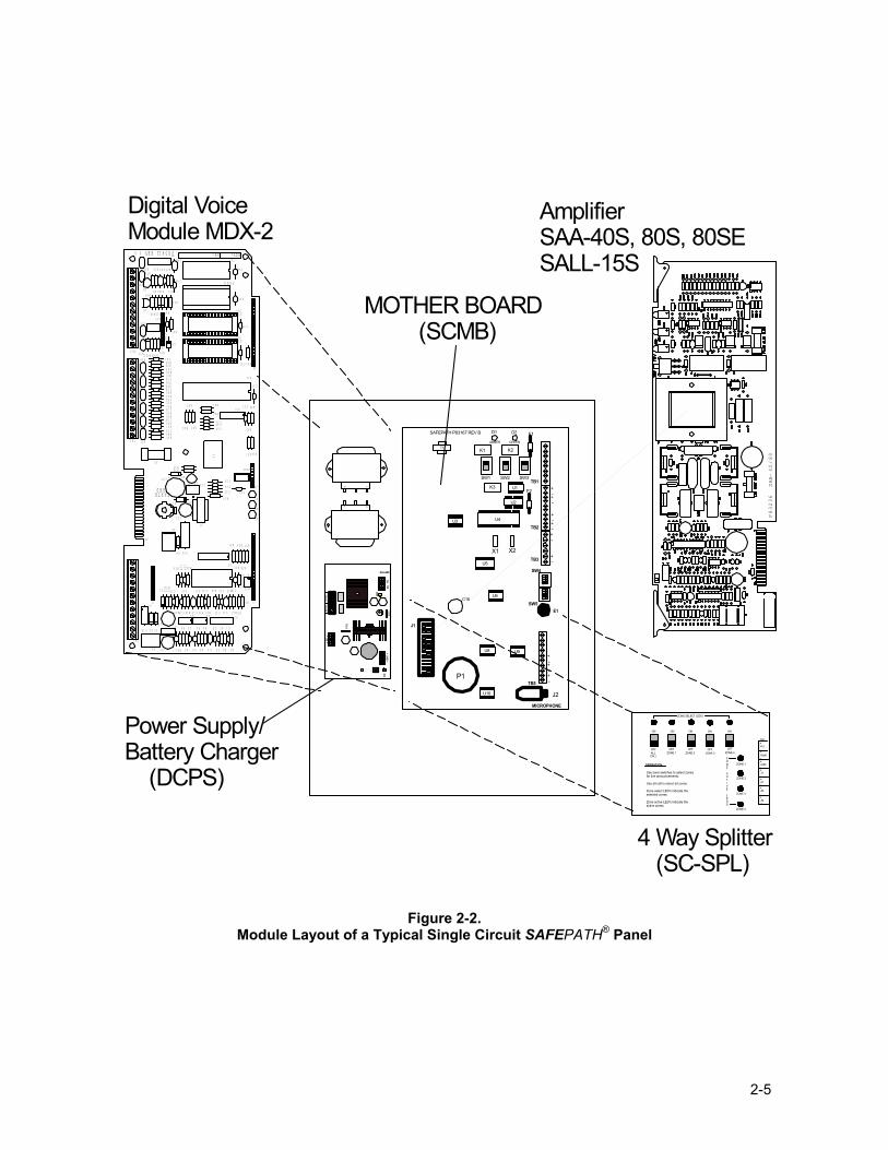
Figure 2-2 Module Layout of a Typical Single Circuit SAFEPATH® Panel������� 2-5
Figure 3-1 Location of Plug-in Modules and Wire Connections������������ 3-2
Figure 3-2 Strobe and Audio Output Connections�����������������. 3-3
Figure 3-3 Wiring Diagram for Visual Notification Appliance Output���������� 3-5
Figure 3-4 Wiring Diagram for Combination Audio/Visual Notification Appliances in
Central Amplifier Applications���������������������. 3-6
Figure 3-5 Wiring Diagram for Combination Audio/Visual Notification Appliances in
Central Amplifier Applications���������������������. 3-6
Figure 3-6 Wiring Diagram for Audio Notification Appliance Output���������� 3-7
Figure 3-7 Wiring Diagram for Combination Audio/Visual Notification Appliances in
Central Amplifier Applications���������������������. 3-7
Figure 3-8 Wiring Diagram for Audio Notification Appliances in Amplified Speaker
Applications����������������������������� 3-8
Figure 3-9 Wiring Diagram for Combination Audio/Visual Notification Appliances in
Amplified Speaker Applications��������������������.. 3-8
Figure 3-10 Wiring Connection Locations��������������������� 3-9
Figure 3-11 Dry Contact Input Connections��������������������. 3-10
Figure 3-12 Alarm and Trouble Status Output Connections�������������. 3-10
Figure 3-13 Alarm Relay Contacts������������������������ 3-11
Figure 3-14 Trouble Status Relay Contacts��������������������. 3-11
Figure 3-15 Trouble Audible Connection���������������������. 3-12
Figure 3-16 Input Power and Battery Connection Locations������������� 3-13
Figure 3-17 Single Circuit SAFEPATH® Panel Mounting��������������. 3-14
Figure 3-18 Configuration DIP Switch Location on SCMB Module����������.. 3-16
Figure 5-1 Single Circuit SAFEPATH® Panel Operator Console����������� 5-3
Figure 7-1 Trouble LED Locations������������������������ 7-2
Figure 7-2 Basic Troubleshooting Flowchart�������������������.. 7-4
Figure 7-3 Digital Voice Module (MDX-2) Troubleshooting Flowchart��������� 7-6
Figure 7-4 Single Circuit SAFEPATH® Module Wiring Diagram.����������.. 7-13
Figure 9-1 Location of Plug-in Modules���������������������� 9-2
Figure 9-2 Single Circuit SAFEPATH® Motherboard (SCMB)������������. 9-5
Figure 9-3 Digital Voice Module (MDX-2)�����..���������������. 9-7
Figure 9-4 Power Supply/Battery Charger (DCPS)���..������������� 9-8
Figure 9-5 Supervised Audio System Amplifier/Signal Circuit Module, 40 Watts
(SAA-40S)�����������������������������. 9-10

viii
Figure 9-6 Supervised Audio System Amplifier/Signal Circuit Module, 80 Watts
(SAA-80S/SE)���������������������������� 9-12
Figure 9-7 Supervised Audio Line Level Module (SALL-15S)������������. 9-14
Figure 9-8 Notification Appliance Circuit Interface Module (NACIM)���������� 9-15
Figure 9-9 4-Zone Splitter Module (SC-SPL)�������������������. 9-16
Figure 9-10 Auxiliary Input Module (AIM-3)��������������������. 9-18
Figure 9-11 Remote Microphone Station (RMS-2)�����������������. 9-19
ix
LIST OF TABLES
Table 3-1 SCMB DIP Switch Setting Description������������������ 3-17
Table 3-2 DIP Switch Settings for Available Tone Sounds�������������� 3-17
Table 3-3 Standby Current for Single Circuit SAFEPATH® Panel����������.. 3-20
Table 3-4 Standby and Alarm Current for Single Circuit SAFEPATH® Modules����.. 3-21
Table 3-5 Standby Current for Single Circuit SAFEPATH® Amplifier Modules�����. 3-21
Table 3-6 Calculations for Amplifier Alarm Current������������..����. 3-22
Table 3-7 Average Current Output Measured by Wheelock, Inc������.����� 3-22
Table 4-1 Alarm Conditions and Results���������������������.. 4-3
Table 6-1 Miscellaneous Hardware Tests���������������..�����. 6-1
Table 7-1 Module Trouble Procedure Cross Reference��������������� 7-3
Table 7-2 MDX-2 Trouble Procedure Cross Reference���������������. 7-3
Table 8-1 Outputs�������������������������������. 8-2

x
Intentionally Blank
1-1
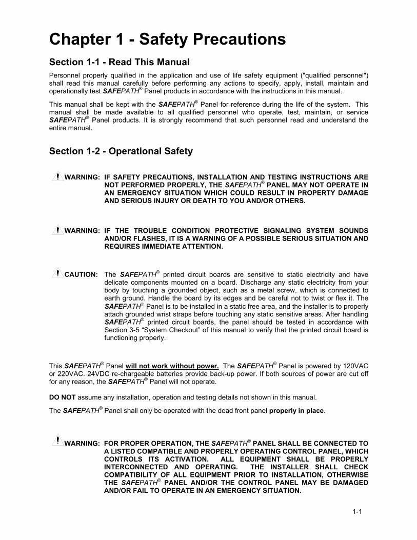
Chapter 1 - Safety Precautions Section 1-1 - Read This Manual Personnel properly qualified in the application and use of life safety equipment ("qualified personnel") shall read this manual carefully before performing any actions to specify, apply, install, maintain and operationally test SAFEPATH® Panel products in accordance with the instructions in this manual.
This manual shall be kept with the SAFEPATH® Panel for reference during the life of the system. This manual shall be made available to all qualified personnel who operate, test, maintain, or service SAFEPATH® Panel products. It is strongly recommend that such personnel read and understand the entire manual.
Section 1-2 - Operational Safety
WARNING: IF SAFETY PRECAUTIONS, INSTALLATION AND TESTING INSTRUCTIONS ARE NOT PERFORMED PROPERLY, THE SAFEPATH® PANEL MAY NOT OPERATE IN AN EMERGENCY SITUATION WHICH COULD RESULT IN PROPERTY DAMAGE AND SERIOUS INJURY OR DEATH TO YOU AND/OR OTHERS.
WARNING: IF THE TROUBLE CONDITION PROTECTIVE SIGNALING SYSTEM SOUNDS AND/OR FLASHES, IT IS A WARNING OF A POSSIBLE SERIOUS SITUATION AND REQUIRES IMMEDIATE ATTENTION.
CAUTION: The SAFEPATH® printed circuit boards are sensitive to static electricity and have delicate components mounted on a board. Discharge any static electricity from your body by touching a grounded object, such as a metal screw, which is connected to earth ground. Handle the board by its edges and be careful not to twist or flex it. The SAFEPATH Panel is to be installed in a static free area, and the installer is to properly attach grounded wrist straps before touching any static sensitive areas. After handling SAFEPATH® printed circuit boards, the panel should be tested in accordance with Section 3-5 �System Checkout� of this manual to verify that the printed circuit board is functioning properly.
This SAFEPATH® Panel will not work without power. The SAFEPATH® Panel is powered by 120VAC or 220VAC. 24VDC re-chargeable batteries provide back-up power. If both sources of power are cut off for any reason, the SAFEPATH® Panel will not operate. DO NOT assume any installation, operation and testing details not shown in this manual.
The SAFEPATH® Panel shall only be operated with the dead front panel properly in place.
WARNING: FOR PROPER OPERATION, THE SAFEPATH® PANEL SHALL BE CONNECTED TO
A LISTED COMPATIBLE AND PROPERLY OPERATING CONTROL PANEL, WHICH CONTROLS ITS ACTIVATION. ALL EQUIPMENT SHALL BE PROPERLY INTERCONNECTED AND OPERATING. THE INSTALLER SHALL CHECK COMPATIBILITY OF ALL EQUIPMENT PRIOR TO INSTALLATION, OTHERWISE THE SAFEPATH® PANEL AND/OR THE CONTROL PANEL MAY BE DAMAGED AND/OR FAIL TO OPERATE IN AN EMERGENCY SITUATION.
1-2
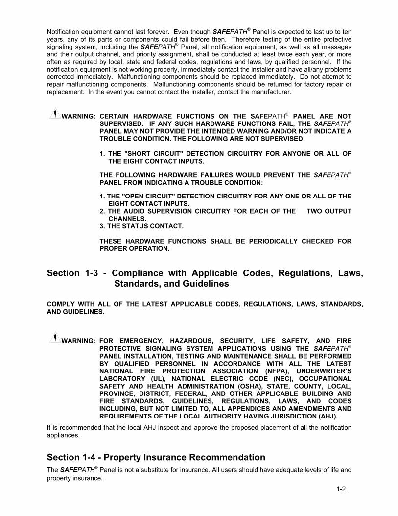
Notification equipment cannot last forever. Even though SAFEPATH® Panel is expected to last up to ten years, any of its parts or components could fail before then. Therefore testing of the entire protective signaling system, including the SAFEPATH® Panel, all notification equipment, as well as all messages and their output channel, and priority assignment, shall be conducted at least twice each year, or more often as required by local, state and federal codes, regulations and laws, by qualified personnel. If the notification equipment is not working properly, immediately contact the installer and have all/any problems corrected immediately. Malfunctioning components should be replaced immediately. Do not attempt to repair malfunctioning components. Malfunctioning components should be returned for factory repair or replacement. In the event you cannot contact the installer, contact the manufacturer.
WARNING: CERTAIN HARDWARE FUNCTIONS ON THE SAFEPATH PANEL ARE NOT SUPERVISED. IF ANY SUCH HARDWARE FUNCTIONS FAIL, THE SAFEPATH® PANEL MAY NOT PROVIDE THE INTENDED WARNING AND/OR NOT INDICATE A TROUBLE CONDITION. THE FOLLOWING ARE NOT SUPERVISED:
1. THE "SHORT CIRCUIT" DETECTION CIRCUITRY FOR ANYONE OR ALL OF
THE EIGHT CONTACT INPUTS.
THE FOLLOWING HARDWARE FAILURES WOULD PREVENT THE SAFEPATH PANEL FROM INDICATING A TROUBLE CONDITION:
1. THE "OPEN CIRCUIT" DETECTION CIRCUITRY FOR ANY ONE OR ALL OF THE
EIGHT CONTACT INPUTS. 2. THE AUDIO SUPERVISION CIRCUITRY FOR EACH OF THE TWO OUTPUT
CHANNELS. 3. THE STATUS CONTACT.
THESE HARDWARE FUNCTIONS SHALL BE PERIODICALLY CHECKED FOR PROPER OPERATION.
Section 1-3 - Compliance with Applicable Codes, Regulations, Laws, Standards, and Guidelines
COMPLY WITH ALL OF THE LATEST APPLICABLE CODES, REGULATIONS, LAWS, STANDARDS, AND GUIDELINES.
WARNING: FOR EMERGENCY, HAZARDOUS, SECURITY, LIFE SAFETY, AND FIRE
PROTECTIVE SIGNALING SYSTEM APPLICATIONS USING THE SAFEPATH
PANEL INSTALLATION, TESTING AND MAINTENANCE SHALL BE PERFORMED BY QUALIFIED PERSONNEL IN ACCORDANCE WITH ALL THE LATEST NATIONAL FIRE PROTECTION ASSOCIATION (NFPA), UNDERWRITER�S LABORATORY (UL), NATIONAL ELECTRIC CODE (NEC), OCCUPATIONAL SAFETY AND HEALTH ADMINISTRATION (OSHA), STATE, COUNTY, LOCAL, PROVINCE, DISTRICT, FEDERAL, AND OTHER APPLICABLE BUILDING AND FIRE STANDARDS, GUIDELINES, REGULATIONS, LAWS, AND CODES INCLUDING, BUT NOT LIMITED TO, ALL APPENDICES AND AMENDMENTS AND REQUIREMENTS OF THE LOCAL AUTHORITY HAVING JURISDICTION (AHJ).
It is recommended that the local AHJ inspect and approve the proposed placement of all the notification appliances.
Section 1-4 - Property Insurance Recommendation The SAFEPATH® Panel is not a substitute for insurance. All users should have adequate levels of life and property insurance.
1-3
Section 1-5 - Audio Output Considerations
WARNING: AUDIBLE SIGNALS MAY MASK MEDICAL EQUIPMENT MONITORING ALARMS. WHERE MEDICAL EQUIPMENT MONITORING ALARMS ARE IN USE, DO NOT USE AUDIBLE SIGNALS; PROVIDE VISUAL NOTIFICATION APPLIANCES IN HIGHLY VISIBLE LOCATIONS.
CAUTION: The output of the audio system may not be heard in all cases. Sound can be blocked or reduced by walls, doors, carpeting, wall coverings, furniture, insulation, bed coverings, and other obstacles that may temporarily or permanently impede the output of the audio system. Sound is also reduced by distance and masked by background noise. The output of the audio system may not be sufficient to alert all occupants, especially those who are asleep, those who are hearing-impaired, those who are wearing devices that plug or cover the ears, and those who have recently used drugs or alcohol. The output of the audio system may not be heard by an alert person if the output device is placed in an area which is isolated by a closed door, or is located on a different floor from the person in a hazardous situation or is placed too far away to be heard over ambient noise such as, but not limited to, running water, traffic, air conditioners, machinery or musical appliances.
If live microphone announcements, audible tones and/or voice messages cannot be readily heard and understood clearly within the protected areas as intended, it will be necessary to increase the number and/or sound output intensity of speakers within those areas so that they are heard and understood clearly when activated.
Section 1-6 - RF Interference The SAFEPATH® Panel has been tested and found to comply with the limits for a Class A digital device, pursuant to Part 15 of the FCC Rules. These limits are designed to provide reasonable protection against harmful interference when the equipment is operated in a commercial environment. This equipment generates, uses, and can radiate radio frequency energy and, if not installed and used in accordance with the instruction manual, may cause harmful interference to radio communications. Operation of this equipment in a residential area is likely to cause harmful interference in which case the user will be required to correct the interference at owners expense.
Section 1-7 - General Each manufacturer's fire alarm control panel, and notification appliances operate differently and have different features. Before specifying, installing, operating, testing, maintaining or servicing a system, carefully read the installation, operation and testing manual for each piece of equipment and applicable codes.
Additional copies of this manual may be obtained from:
Wheelock, Inc. 273 Branchport Ave. Long Branch, N.J. 07740 Tel: (732) 222- 6880 Fax: (732) 222- 2588
Email: infoatwheelockinc.com

1-4
Intentionally Blank
2-1
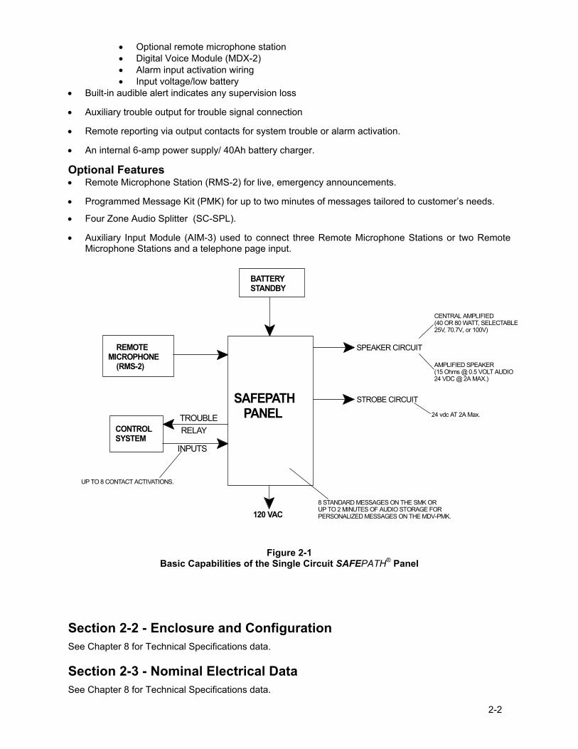
Chapter 2 - Overview and Features Section 2-1- Description General The Single Circuit SAFEPATH® Panel is a stand alone, single channel, supervised audio fire and emergency evacuation system. Figure 2-1 on Page 2-2 illustrates the basic capabilities of the Single Circuit SAFEPATH Panel.
The control panel that activates the Single Circuit SAFEPATH Panel can range from simple push buttons to a sophisticated computer based control panel providing dry contact closures. The SAFEPATH Panel does not sense an emergency condition or hazards such as fire; it is only a part of a system that does sense such conditions. The SAFEPATH Panel, when activated, provides a pre-recorded tone and/or voice message(s) to notification appliances. When used as part of a protective signaling system, the SAFEPATH Panel must be properly connected to a compatible control panel that has been approved by a nationally recognized testing laboratory ("LISTED") and to LISTED compatible notification appliances for proper operation. THE SAFEPATH PANEL MUST BE PROPERLY INSTALLED, PROGRAMMED, AND CONNECTED TO A COMPATIBLE FIRE ALARM CONTROL PANEL TO FUNCTION IN A VOICE EVACUATION SYSTEM.
WHEELOCK EXPRESSLY DISCLAIMS ALL LIABILITY FOR THE CONTENT, CLARITY AND LANGUAGES OF, AND OUTPUT CHANNEL AND PRIORITY LEVEL ASSIGNED TO, ANY AND ALL MESSAGES. IT IS ESSENTIAL THAT YOU HAVE MESSAGE CONTENT AND LANGUAGE, SEQUENCE, OUTPUT CHANNEL AND PRIORITY ASSIGNMENTS REVIEWED AND APPROVED BY QUALIFIED LEGAL AND SAFETY ADVISORS, QUALIFIED REPRESENTATIVE(S) OF OWNER(S) AND USER(S), AND AUTHORITIES HAVING JURISDICTION.
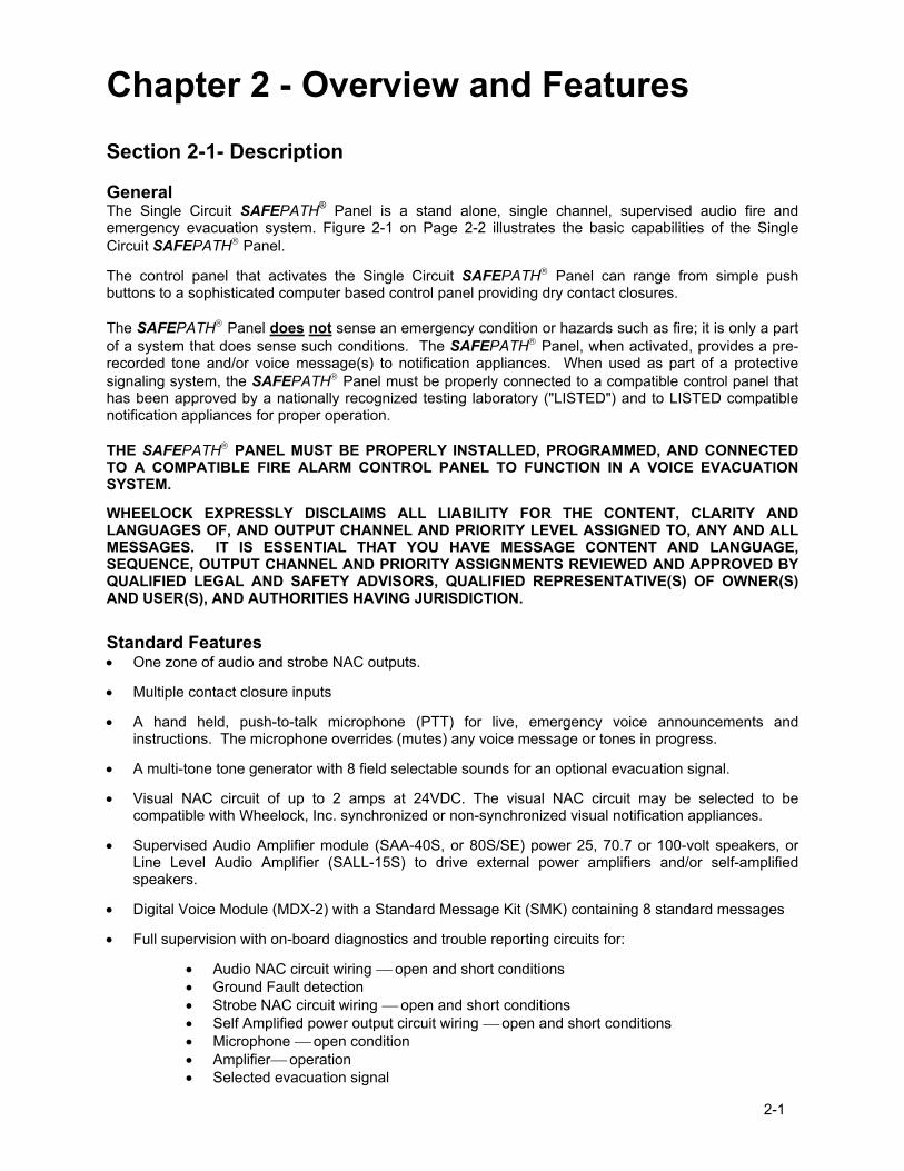
Standard Features • One zone of audio and strobe NAC outputs.
• Multiple contact closure inputs
• A hand held, push-to-talk microphone (PTT) for live, emergency voice announcements and instructions. The microphone overrides (mutes) any voice message or tones in progress.
• A multi-tone tone generator with 8 field selectable sounds for an optional evacuation signal.
• Visual NAC circuit of up to 2 amps at 24VDC. The visual NAC circuit may be selected to be compatible with Wheelock, Inc. synchronized or non-synchronized visual notification appliances.
• Supervised Audio Amplifier module (SAA-40S, or 80S/SE) power 25, 70.7 or 100-volt speakers, or Line Level Audio Amplifier (SALL-15S) to drive external power amplifiers and/or self-amplified speakers.
• Digital Voice Module (MDX-2) with a Standard Message Kit (SMK) containing 8 standard messages
• Full supervision with on-board diagnostics and trouble reporting circuits for:
• Audio NAC circuit wiring open and short conditions • Ground Fault detection • Strobe NAC circuit wiring open and short conditions • Self Amplified power output circuit wiring open and short conditions • Microphone open condition • Amplifier operation • Selected evacuation signal
2-2
• Optional remote microphone station • Digital Voice Module (MDX-2) • Alarm input activation wiring • Input voltage/low battery
• Built-in audible alert indicates any supervision loss
• Auxiliary trouble output for trouble signal connection
• Remote reporting via output contacts for system trouble or alarm activation.
• An internal 6-amp power supply/ 40Ah battery charger.
Optional Features • Remote Microphone Station (RMS-2) for live, emergency announcements.
• Programmed Message Kit (PMK) for up to two minutes of messages tailored to customer�s needs.
• Four Zone Audio Splitter (SC-SPL).
• Auxiliary Input Module (AIM-3) used to connect three Remote Microphone Stations or two Remote Microphone Stations and a telephone page input.
CONTROLSYSTEM
120 VAC
REMOTE MICROPHONE (RMS-2)
BATTERYSTANDBY
SAFEPATH PANEL
SPEAKER CIRCUIT
STROBE CIRCUIT
INPUTS
TROUBLERELAY
8 STANDARD MESSAGES ON THE SMK ORUP TO 2 MINUTES OF AUDIO STORAGE FORPERSONALIZED MESSAGES ON THE MDV-PMK.
UP TO 8 CONTACT ACTIVATIONS.
AMPLIFIED SPEAKER(15 Ohms @ 0.5 VOLT AUDIO24 VDC @ 2A MAX.)
24 vdc AT 2A Max.
CENTRAL AMPLIFIED(40 OR 80 WATT, SELECTABLE25V, 70.7V, or 100V)
Figure 2-1
Basic Capabilities of the Single Circuit SAFEPATH® Panel
Section 2-2 - Enclosure and Configuration See Chapter 8 for Technical Specifications data.
Section 2-3 - Nominal Electrical Data See Chapter 8 for Technical Specifications data.
2-3
Section 2-4 - Module Configurations The Single Circuit SAFEPATH® Panel is equipped with a combination of the following modules:
There are ten modules in the Single Circuit SAFEPATH Panel product line. The ten modules are:
SCMB (Single Circuit Motherboard)
DCPS (Power Supply/Battery Charger)
SAA-40S (40 Watt, Supervised Audio Amplifier Module with 2 Amps of strobe current)
SAA-80S/SE* (80 Watt, Supervised Audio Amplifier Module with 2 Amps of strobe current)
SALL-15S (Line Level, Supervised Audio Amplifier Module with 2 Amps of strobe current)
SC-SPL (Single Circuit Splitter - 4 Zone)
NACIM (Notification Appliance Circuit Interface Module)
MDX-2 (Digital Voice Module)
RMS-2 (Single Circuit Remote Microphone Station)
AIM-3 (Auxiliary Input Module) * 100 Volt for Export Installations
Section 2-5 - Single Circuit SAFEPATH® Panel Basic Configuration Each Single Circuit SAFEPATH Panel is configured with: SCMB (Single Circuit Motherboard)
MDX-2 (Digital Voice Module) SMK (Standard Message Kit) or optional PMK (Programmed Message Kit)
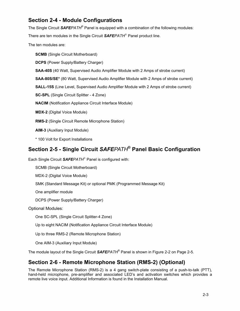
One amplifier module DCPS (Power Supply/Battery Charger) Optional Modules: One SC-SPL (Single Circuit Splitter-4 Zone) Up to eight NACIM (Notification Appliance Circuit Interface Module) Up to three RMS-2 (Remote Microphone Station) One AIM-3 (Auxiliary Input Module) The module layout of the Single Circuit SAFEPATH® Panel is shown in Figure 2-2 on Page 2-5.
Section 2-6 - Remote Microphone Station (RMS-2) (Optional) The Remote Microphone Station (RMS-2) is a 4 gang switch-plate consisting of a push-to-talk (PTT), hand-held microphone, pre-amplifier and associated LED�s and activation switches which provides a remote live voice input. Additional Information is found in the Installation Manual.
2-4
Section 2-7 - Operation Modes The SAFEPATH® Panel has two operation modes:
1. Standby 2. Alarm
Standby Mode Standby is the normal mode. The SAFEPATH® Panel supervises the connections and internal components to maintain proper operation. All strobes and speaker appliances are off.
Alarm Mode Alarm mode occurs when an emergency signal is initiated manually, or by the FACP or control equipment.
Section 2-8 � Glossary of Terms AHJ � Authority Having Jurisdiction
EOLR � End of Line Resistor
FACP � Fire Alarm Control Panel
NAC � Notification Appliance Circuit
NEC � National Electric Code (NFPA-70)
NFPA � National Fire Protection Association
PTT � Push to Talk (Microphone)
PCB - Printed Circuit Board
UL - Underwriters Laboratory
2-5
106
10 6
4 Way Splitter (SC-SPL)
AmplifierSAA-40S, 80S, 80SESALL-15S
Digital VoiceModule MDX-2
P83236 SAA-40/80
S15
S14
S12
CH1 VOL
P83412 REV ( )
EARTHGND
REV:SN:
TB2
R46
RV1
C33
D13
D12
R59R60
R57R58
R55R56
R53R54
R51R52
R49R50
R47R48
R62
U17
U13
C48
C41
C40
C39
C38
C36
C35
C34
TB3
RV8
R72
RV9
RV10
R69
R68Q1
R73
Q2
RV5
R64 R63D11RV7
RV6
RV3
RV4
RV2
J5
J6
R65
U14
C43
C44
R71
U16C50
C49C47
U15
R66
R67
R70
C46
C45
U11
C42
C32
U12
D10
R41
R40
C30
C31
C29C28
R43
R44 R42
U10
R61
C37
R39
R38
C9
E1
F1
K1
R45
D3
J3
TB1
J2
C10 D2 D1
C8 R9 R2R5R7 R1C4 C2C7 C5
R32
K2
J1
D4
U8
C23
U7C27
C24C25
R34R35
D9
L2
U9
C26
L1
C21
D8R33
C22
J4
R36R37
D5
D7
D6
R28
R23
R10
R19 R13
R21R22 R14R17C17 C14 C12
U5
U6
C20
C19R26 R25 R30
R31 R29
R24C18
R16U3U4
C16R20 R18 C15
R8U1 R6C6
U2C11R15 C13 R11R12
R3R4 C3 C1
R27
+
+
+
+
+
S8
12
34
ON
12
34
ON
J1
MICROPHONE
TB5
E1SW5
SW4
TB3
TB2
TB1SW1 SW2 SW3
K1 K2
K3
F1
F2
X1 X2
J2
P1
C16
D1 D2
U1
U2
U3 U4
U5
U6
U8 U9
U10
+-
+-+-
+-
+-+-
T1
+-
+-
+-
SAFEPATH P83167 REV B
AMBER GREEN
DCBA
T+
-SW
1
AC
ACAC
+-
DC
SW2
BAT
FAIL
NO N
C C
AC
FAIL
C NC
NO
SMP7PM
Power Supply/Battery Charger (DCPS)
ZONE SELECT LED'S
ON
OFF
ON ON
OFF OFF
ON
OFF
ON
OFF ALL CALL
ZONE 1 ZONE 2 ZONE 3 ZONE 4
ZONE 1
ZONE 2
ZONE 3
ZONE 4
ZONE
ACTIVE
LEDS
Z4
Z3
Z2
Z1
AUD
PWR
ALL
TB1
+
_+_
+_+_
+_
+
_
+_
OPERATION:
Use zone switches to select zonesfor live announcements.
Use all-call to select all zones.
Zone select LED's indicate theselected zones.
Zone active LED's indicate theactive zones.
MOTHER BOARD (SCMB)
Figure 2-2.
Module Layout of a Typical Single Circuit SAFEPATH® Panel

2-6
Intentionally Blank
3-1
Chapter 3 - Installation and Setup
Section 3-1 - Introduction The lives of people depend upon the safe and proper installation of the SAFEPATH® Panel. Please read, understand and carefully follow the specific installation instructions set forth below to avoid damage to the SAFEPATH® Panel and equipment connected to it. Only qualified personnel in accordance with the procedures in this manual should conduct installation.
WARNING: SHUT OFF ALL POWER BEFORE STARTING THE INSTALLATION. ELECTRICAL SHOCK CAN CAUSE DEATH OR SERIOUS INJURY.
WARNING: DO NOT CONNECT AC POWER OR BATTERY BACKUP POWER UNTIL SYSTEM
WIRING HAS BEEN CONNECTED, MODULES HAVE BEEN INSTALLED, AND FIELD WIRING HAS BEEN INSPECTED.
CAUTION: The SAFEPATH® printed circuit boards are sensitive to static electricity and have delicate components mounted on them. Before handling either a board or any component on a board, discharge any static electricity from your body by touching a grounded object such as a metal screw, which is connected to earth, ground. Handle the board by its edges, and be careful not to twist or flex it. The SAFEPATH® Panel is to be installed in a static free area and the user is to properly attach grounded wrist straps before touching any static sensitive areas. After handling SAFEPATH® printed circuit boards, verify that the printed circuit boards are undamaged and functioning properly.
The installer, prior to installation should consult with the authorities having jurisdiction (AHJ).
Section 3-2 - Fire Alarm Control Panel Interface Wiring Applications The SAFEPATH® Panel can be connected to either the FACP alarm output dry contact or to the FACP Notification Appliance Circuit (NAC). If it is connected to the NAC, then the Notification Appliance Circuit Interface Module (NACIM) shall be used. Follow the NACIM instruction sheet (P83478) for proper mounting and wiring.
The SAFEPATH® Panel may be connected to either a �silenceable� or �non-silenceable� notification appliance circuit depending upon system requirements. When the SAFEPATH® Panel is connected to a �silenceable� NAC circuit on the FACP, activating the FACP�s alarm silence switch will silence it. The Strobe NAC circuit on the SAFEPATH® Panel will also be silenced. In order for the strobes to remain in alarm when the audible is silenced, the Strobe NAC circuit must be connected to a �non-silenceable� NAC circuit on the FACP.
A SAFEPATH® Panel connected to a �non-silenceable� NAC circuit cannot be silenced from the FACP.
�TROUBLE�, Form C relay terminals are available for monitoring the condition of the SAFEPATH® Panel at the FACP.
3-2
IN8IN7
IN6
IN5IN4IN3IN2IN1
Digital VoiceModule MDX-2
S15
S14
S12
CH1 VOL
P83412 REV ( )
EARTHGND
REV:SN:
TB2
R46
RV1
C33
D13
D12
R59R60
R57R58
R55R56
R53R54
R51R52
R49R50
R47R48
R62
U17
U13
C48
C41
C40
C39
C38
C36
C35
C34
TB3
RV8
R72
RV9
RV10
R69
R68Q1
R73
Q2
RV5
R64 R63D11RV7
RV6
RV3
RV4
RV2
J5
J6
R65
U14
C43
C44
R71
U16C50
C49C47
U15
R66
R67
R70
C46
C45
U11
C42
C32
U12
D10
R41
R40
C30
C31
C29C28
R43
R44 R42
U10
R61
C37
R39
R38
C9
E1
F1
K1
R45
D3
J3
TB1
J2
C10 D2 D1
C8 R9 R2R5R7 R1C4 C2C7 C5
R32
K2
J1
D4
U8
C23
U7C27
C24C25
R34R35
D9
L2
U9
C26
L1
C21
D8R33
C22
J4
R36R37
D5
D7
D6
R28
R23
R10
R19 R13
R21R22 R14R17C17 C14 C12
U5
U6
C20
C19R26 R25 R30
R31 R29
R24C18
R16U3U4
C16R20 R18 C15
R8U1 R6C6
U2C11R15 C13 R11R12
R3R4 C3 C1
R27
+
+
+
+
+
S8
12
34
ON
12
34
ON
J1
MICROPHONE
TB5
E1SW5
SW4
TB3
TB2
TB1SW1 SW2 SW3
K1 K2
K3
F1
F2
X1 X2
J2P1
C16
D1 D2
U1
U2
U3 U4
U5
U6
U8 U9
U10
+-
+-+-
+-
+-+-
T1
+-
+-
+-
SAFEPATH P83167 REV B
AMBER GREEN
BAT
+-
TB2 RV1
TB3
RV8
RV5
D11RV7
RV6
RV3
RV4
RV2
TRB AUD
TRB COMTRB NOTRB NCALARM COMALARM NOALARM NC
DV POWER
DV STATUS
CH PLAY
LINE OUT
LINE IN
RM AUDIO
RM TXDRM RXD
RM POWER
+
+-
-
TONE SEL321CND FLT ENB
RM ENABLESYNCDV ENABLELAMP TEST
AUDIO
STROBE
SPK AMP
24V
ALL CALL
+-
+-
TB1
TRB AUD
TRB COMTRB NOTRB NCALARM COMALARM NOALARM NC
+-
TB3 +-
+-RM AUDIO
RM TXDRM RXD
RM POWER
12
34
ON
12
34
ON
SW5
SW4 TONE SEL321CND FLT ENB
RM ENABLESYNCDV ENABLELAMP TEST
TB5+-
+-
+-
AUDIO
STROBE
SPK AMP
24V
ALL CALL
+-
+-
Amplifier Connector
BATTERY CONNECTION
SECTION 1 INPUTCONNECTIONS
SECTION 2STATUS AND TROUBLE CONNECTIONS
SECTION 3 REMOTE MICROPHONE STATION AND AIM-3 CONNECTIONS
SECTION 4CONFIGURATION DIP SWITCHES
SECTION 5 STROBE AND AUDIOOUTPUT CONNECTIONS
EARTHGROUND
GROUNDFAULTADJUST
R53
GROUNDFAULTADJUST
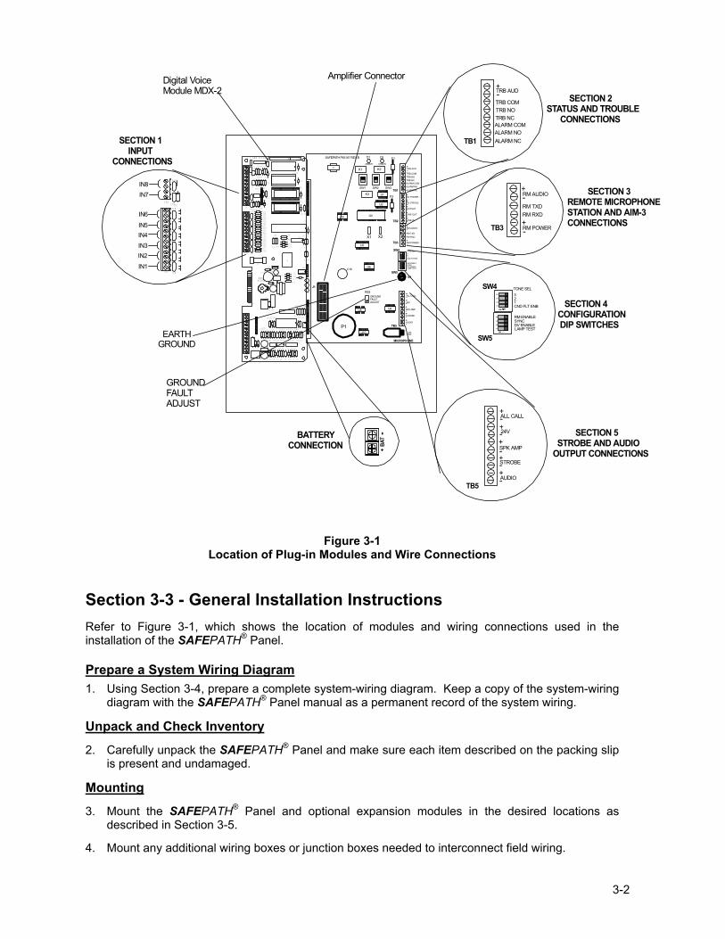
Figure 3-1
Location of Plug-in Modules and Wire Connections
Section 3-3 - General Installation Instructions Refer to Figure 3-1, which shows the location of modules and wiring connections used in the installation of the SAFEPATH® Panel. Prepare a System Wiring Diagram 1. Using Section 3-4, prepare a complete system-wiring diagram. Keep a copy of the system-wiring
diagram with the SAFEPATH® Panel manual as a permanent record of the system wiring.
Unpack and Check Inventory
2. Carefully unpack the SAFEPATH® Panel and make sure each item described on the packing slip is present and undamaged.
Mounting
3. Mount the SAFEPATH® Panel and optional expansion modules in the desired locations as described in Section 3-5.
4. Mount any additional wiring boxes or junction boxes needed to interconnect field wiring.
3-3
5. Connect conduit fittings or bushings as needed through the knockouts provided on the top and bottom of the SAFEPATH® Panel.
Field Wiring Connections
6. Install field wiring in conduit when required, following the most current National Electrical Code (NFPA-70) and local codes for the type of system being installed. Make all necessary connections at any additional wiring or junction boxes.
7. Wire all ancillary equipment, power connections, and Fire Alarm Control Panel correctly and prepare all wires for hookup to the SAFEPATH® Panel. Do not connect Ancillary equipment or NAC speaker and strobe appliance wiring to the SAFEPATH Panel. This will be done starting with Step 13 of this procedure.
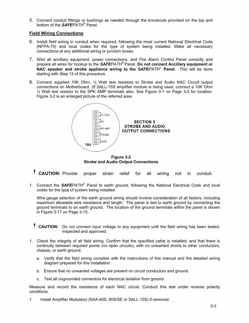
8. Connect supplied 10K Ohm, ¼ Watt test resistors to Strobe and Audio NAC Circuit output connections on Motherboard. (If SALL-15S amplifier module is being used, connect a 10K Ohm ¼ Watt test resistor to the SPK AMP terminals also. See Figure 3-1 on Page 3-2 for location. Figure 3-2 is an enlarged picture of the referred area.
TB5+-
+-
+-
AUDIO
STROBE
SPK AMP
24V
ALL CALL
+-
+-
SECTION 5 STROBE AND AUDIOOUTPUT CONNECTIONS
Figure 3-2
Strobe and Audio Output Connections
CAUTION: Provide proper strain relief for all wiring not in conduit.
1. Connect the SAFEPATH Panel to earth ground, following the National Electrical Code and local codes for the type of system being installed.
Wire gauge selection of the earth ground wiring should involve consideration of all factors, including maximum allowable wire resistance and length. The panel is tied to earth ground by connecting the ground terminals to an earth ground. The location of the ground terminals within the panel is shown in Figure 3-17 on Page 3-15.
CAUTION: Do not connect input voltage to any equipment until the field wiring has been tested, inspected and approved.
1. Check the integrity of all field wiring. Confirm that the specified cable is installed, and that there is continuity between required points (no open circuits), with no unwanted shorts to other conductors, chassis, or earth ground.
a. Verify that the field wiring complies with the instructions of this manual and the detailed wiring diagram prepared for this installation.
b. Ensure that no unwanted voltages are present on circuit conductors and ground.
c. Test all ungrounded connectors for electrical isolation from ground.
Measure and record the resistance of each NAC circuit. Conduct this test under reverse polarity conditions.
1. Install Amplifier Module(s) (SAA-40S, 80S/SE or SALL-15S) if removed.
3-4
Initial Checkout
WARNING: TWO DIFFERENT SOURCES OF POWER MAY BE CONNECTED TO THE SAFEPATH® PANEL. DISCONNECT BOTH SOURCES OF POWER BEFORE SERVICING. FAILURE TO DO SO COULD RESULT IN PROPERTY DAMAGE, SERIOUS INJURY, OR DEATH TO YOU AND/OR OTHERS.
CAUTION: Connect the AC power source before connecting the battery backup power. Disconnect the battery backup power before disconnecting the AC power source.
1. Conduct the Initial Checkout procedures as described in Section 3-6 System Checkout.
Final Checkout
2. Remove all EOLRs on Audio and Visual NAC Circuits.
3. Connect all Strobe and Speaker NAC Circuits to the proper connections on the SAFEPATH® Motherboard (SCMB). See Figure 3-2 on Page 3-3.
4. Connect all Optional Equipment to the SAFEPATH® Panel in accordance with each Installation Sheet.
5. If the Strobe NAC Circuit is not being used connect a Wheelock, Inc. LISTED 10K Ohm, 1W EOLR to the terminals on the Mother Board.
6. If Ground Fault Detection is required, connect and align according to Section 3-7 Ground Fault Detection Sensitivity Adjustment.
7. Perform Final Checkout Procedures as described in Section 3-6 System Checkout.
8. Calculate and Install properly sized backup batteries. (Section 3-8)
Section 3-4 � Prepare a System Wiring Diagram
Wiring Guidelines
Although the SAFEPATH Panel products incorporate signal verification and noise filtering circuitry on their inputs, induced voltages or noise on the input wiring can cause improper operation. Therefore, use shielded twisted pair wire for all dry contact input wiring. The shield of each cable should be connected only at one end. Each shield of each cable that connects to the SAFEPATH Panel is to be connected to the grounding points provided near the knockout locations on the chassis (see Figure 3-17 on Page 3-15). The National Electrical Code (NFPA-70) defines two types of circuits for protective signaling systems: power limited circuits and non-power limited circuits. The SAFEPATH® Panel circuits are non-power limited.
WARNING: ALL SAFEPATH® PANEL DRY CONTACT INPUT WIRING AND AUDIO WIRING SHOULD BE ROUTED AWAY FROM ANY HIGH VOLYAGE OR HIGH CURRENT WIRING (SUCH AS AC OR DC POWER WIRING, AUDIO POWER WIRING, AND MOTOR OR RELAY ACTUATION WIRING). DRY CONTACT INPUT WIRING SHALL BE INSTALLED IN SEPARATE CONDUIT. FAILURE TO DO SO MAY CAUSE ELECTRICAL SHOCK RESULTING IN PROPERTY DAMAGE AND SERIOUS INJURY OR DEATH TO YOU AND/OR OTHERS.
3-5
CAUTION: The National Electric Code limits the maximum number of conductors that can be installed in conduit and wiring boxes depending on the size of the conduit, the volume of the boxes, and the gauge of the wire used. Make sure that wiring used for SAFEPATH® Panel installation complies with the latest NEC, NFPA, Local, State, County or Province requirements.
Field Wiring Connections All SAFEPATH® Panel wiring terminals are designed to accept #12 AWG through #22 AWG wiring (one wire per terminal). Proper wire gage considerations for the NAC Circuit must take into account current requirements versus length of run.
Prepare System Wiring Diagram. 1. Prepare a system-wiring diagram to include all Notification Appliances, ancillary equipment, and
internal connections and power sources as required.
Visual Notification Appliance Output Wiring Available alarm strobe current is a maximum of 2 Amps at 24VDC. Table 3-1 shows available strobe current using the standard calculation for a Temporal Code 3 signal. The SAFEPATH® Panel does not include any optional modules. Complete calculation information for other configurations is located in Section 3-8 Backup Battery Calculations.
Wire gauge may vary for each visual notification appliance output circuit on the panel. Wire gauge selection should involve consideration of all factors including, wire loop length, maximum current draw of each appliance, number of appliances, and maximum voltage drop allowable.
• Strobe NAC has a 24VDC, 2.0 amps maximum output • Strobe NAC meets Class B supervision requirements for notification appliance circuits. • Each output circuit shall have a UL LISTED, 10K Ohm, 1W, EOLR installed across the last visual
notification appliance. If the output is unused, a UL LISTED, 10K Ohm, 1W, EOLR shall be placed across the output terminals. Each amplifier module contains the required number for the supervised outputs. If more are needed, recommend using Wheelock, Inc. End of Line Resistor Kit (Model Number EOLK, Part# 5076), which contains Eight (8) UL LISTED 10K Ohm 1W resistors.
Wiring Diagrams for Visual Portion of Audio/Visual Notification Appliances
+_
STROBE
UL LISTED 10K Ohm1W EOLR
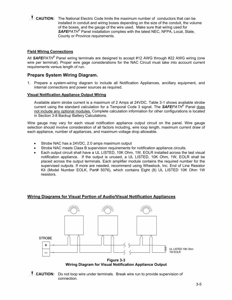
Figure 3-3
Wiring Diagram for Visual Notification Appliance Output
CAUTION: Do not loop wire under terminals. Break wire run to provide supervision of connection.
3-6
+_
+_AUDIO
STROBE
UL LISTED 10K Ohm1W EOLR
UL LISTED 10K Ohm1W EOLR
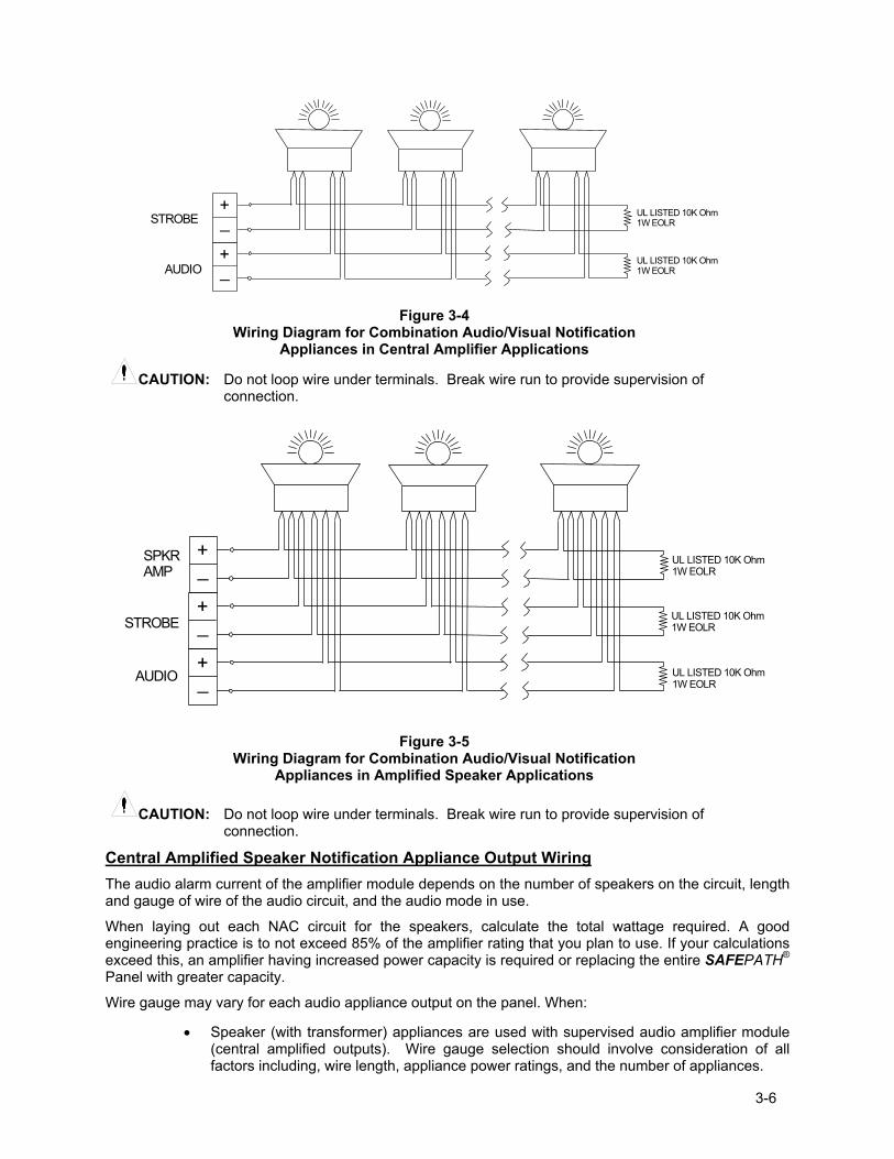
Figure 3-4
Wiring Diagram for Combination Audio/Visual Notification Appliances in Central Amplifier Applications
CAUTION: Do not loop wire under terminals. Break wire run to provide supervision of
connection.
+_
+_
AUDIO
SPKRAMP
+_
STROBE
UL LISTED 10K Ohm1W EOLR
UL LISTED 10K Ohm1W EOLR
UL LISTED 10K Ohm1W EOLR
Figure 3-5
Wiring Diagram for Combination Audio/Visual Notification Appliances in Amplified Speaker Applications
CAUTION: Do not loop wire under terminals. Break wire run to provide supervision of connection.
Central Amplified Speaker Notification Appliance Output Wiring The audio alarm current of the amplifier module depends on the number of speakers on the circuit, length and gauge of wire of the audio circuit, and the audio mode in use.
When laying out each NAC circuit for the speakers, calculate the total wattage required. A good engineering practice is to not exceed 85% of the amplifier rating that you plan to use. If your calculations exceed this, an amplifier having increased power capacity is required or replacing the entire SAFEPATH® Panel with greater capacity. Wire gauge may vary for each audio appliance output on the panel. When:
• Speaker (with transformer) appliances are used with supervised audio amplifier module (central amplified outputs). Wire gauge selection should involve consideration of all factors including, wire length, appliance power ratings, and the number of appliances.
3-7
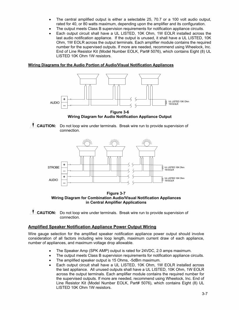
• The central amplified output is either a selectable 25, 70.7 or a 100 volt audio output, rated for 40, or 80 watts maximum, depending upon the amplifier and its configuration.
• The output meets Class B supervision requirements for notification appliance circuits. • Each output circuit shall have a UL LISTED, 10K Ohm, 1W EOLR installed across the
last audio notification appliance. If the output is unused, it shall have a UL LISTED, 10K Ohm, 1W EOLR across the output terminals. Each amplifier module contains the required number for the supervised outputs. If more are needed, recommend using Wheelock, Inc. End of Line Resistor Kit (Model Number EOLK, Part# 5076), which contains Eight (8) UL LISTED 10K Ohm 1W resistors.
Wiring Diagrams for the Audio Portion of Audio/Visual Notification Appliances
+_AUDIO UL LISTED 10K Ohm
1W EOLR
Figure 3-6
Wiring Diagram for Audio Notification Appliance Output
CAUTION: Do not loop wire under terminals. Break wire run to provide supervision of connection.
+_
+_AUDIO
STROBE UL LISTED 10K Ohm1W EOLR
UL LISTED 10K Ohm1W EOLR
Figure 3-7 Wiring Diagram for Combination Audio/Visual Notification Appliances
in Central Amplifier Applications
CAUTION: Do not loop wire under terminals. Break wire run to provide supervision of connection.
Amplified Speaker Notification Appliance Power Output Wiring Wire gauge selection for the amplified speaker notification appliance power output should involve consideration of all factors including wire loop length, maximum current draw of each appliance, number of appliances, and maximum voltage drop allowable.
• The Speaker Amp (SPK AMP) output is rated for 24VDC, 2.0 amps maximum. • The output meets Class B supervision requirements for notification appliance circuits. • The amplified speaker output is 15 Ohms, -5dBm maximum. • Each output circuit shall have a UL LISTED, 10K Ohm, 1W EOLR installed across
the last appliance. All unused outputs shall have a UL LISTED, 10K Ohm, 1W EOLR across the output terminals. Each amplifier module contains the required number for the supervised outputs. If more are needed, recommend using Wheelock, Inc. End of Line Resistor Kit (Model Number EOLK, Part# 5076), which contains Eight (8) UL LISTED 10K Ohm 1W resistors.
3-8
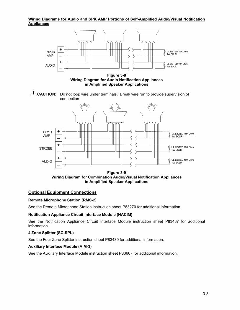
Wiring Diagrams for Audio and SPK AMP Portions of Self-Amplified Audio/Visual Notification Appliances
+_
+_AUDIO
SPKRAMP
UL LISTED 10K Ohm1W EOLR
UL LISTED 10K Ohm1W EOLR
Figure 3-8
Wiring Diagram for Audio Notification Appliances in Amplified Speaker Applications
CAUTION: Do not loop wire under terminals. Break wire run to provide supervision of
connection
+_
+_
AUDIO
SPKRAMP
+_
STROBE
UL LISTED 10K Ohm1W EOLR
UL LISTED 10K Ohm1W EOLR
UL LISTED 10K Ohm1W EOLR
Figure 3-9
Wiring Diagram for Combination Audio/Visual Notification Appliances in Amplified Speaker Applications
Optional Equipment Connections
Remote Microphone Station (RMS-2) See the Remote Microphone Station instruction sheet P83270 for additional information.
Notification Appliance Circuit Interface Module (NACIM) See the Notification Appliance Circuit Interface Module instruction sheet P83487 for additional information.
4 Zone Splitter (SC-SPL) See the Four Zone Splitter instruction sheet P83439 for additional information. Auxiliary Interface Module (AIM-3) See the Auxiliary Interface Module instruction sheet P83667 for additional information.
3-9
INTERNAL WIRING CONNECTIONS
IN8IN7
IN6
IN5IN4IN3IN2IN1
Digital VoiceModule MDX-2
S15
S14
S12
CH1 VOL
P83412 REV ( )
EARTHGND
REV:SN:
TB2
R46
RV1
C33
D13
D12
R59R60
R57R58
R55R56
R53R54
R51R52
R49R50
R47R48
R62
U17
U13
C48
C41
C40
C39
C38
C36
C35
C34
TB3
RV8
R72
RV9
RV10
R69
R68Q1
R73
Q2
RV5
R64 R63D11RV7
RV6
RV3
RV4
RV2
J5
J6
R65
U14
C43
C44
R71
U16C50
C49C47
U15
R66
R67
R70
C46
C45
U11
C42
C32
U12
D10
R41
R40
C30
C31
C29C28
R43
R44 R42
U10
R61
C37
R39
R38
C9
E1
F1
K1
R45
D3
J3
TB1
J2
C10 D2 D1
C8 R9 R2R5R7 R1C4 C2C7 C5
R32
K2
J1
D4
U8
C23
U7C27
C24C25
R34R35
D9
L2
U9
C26
L1
C21
D8R33
C22
J4
R36R37
D5
D7
D6
R28
R23
R10
R19 R13
R21R22 R14R17C17 C14 C12
U5
U6
C20
C19R26 R25 R30
R31 R29
R24C18
R16U3U4
C16R20 R18 C15
R8U1 R6C6
U2C11R15 C13 R11R12
R3R4 C3 C1
R27
+
+
+
+
+
S8
12
34
ON
12
34
ON
J1
MICROPHONE
TB5
E1SW5
SW4
TB3
TB2
TB1SW1 SW2 SW3
K1 K2
K3
F1
F2
X1 X2
J2P1
C16
D1 D2
U1
U2
U3 U4
U5
U6
U8 U9
U10
+-
+-+-
+-
+-+-
T1
+-
+-
+-
SAFEPATH P83167 REV B
AMBER GREEN
BAT
+-
TB2 RV1
TB3
RV8
RV5
D11RV7
RV6
RV3
RV4
RV2
TRB AUD
TRB COMTRB NOTRB NCALARM COMALARM NOALARM NC
DV POWER
DV STATUS
CH PLAY
LINE OUT
LINE IN
RM AUDIO
RM TXDRM RXD
RM POWER
+
+-
-
TONE SEL321CND FLT ENB
RM ENABLESYNCDV ENABLELAMP TEST
AUDIO
STROBE
SPK AMP
24V
ALL CALL
+-
+-
TB1
TRB AUD
TRB COMTRB NOTRB NCALARM COMALARM NOALARM NC
+-
TB3 +-
+-RM AUDIO
RM TXDRM RXD
RM POWER
12
34
ON
12
34
ON
SW5
SW4 TONE SEL321CND FLT ENB
RM ENABLESYNCDV ENABLELAMP TEST
TB5+-
+-
+-
AUDIO
STROBE
SPK AMP
24V
ALL CALL
+-
+-
Amplifier Connector
BATTERY CONNECTION
SECTION 1 INPUTCONNECTIONS
SECTION 2STATUS AND TROUBLE CONNECTIONS
SECTION 3 REMOTE MICROPHONE STATION AND AIM-3 CONNECTIONS
SECTION 4CONFIGURATION DIP SWITCHES
SECTION 5 STROBE AND AUDIOOUTPUT CONNECTIONS
EARTHGROUND
GROUNDFAULTADJUST
R53
GROUNDFAULTADJUST
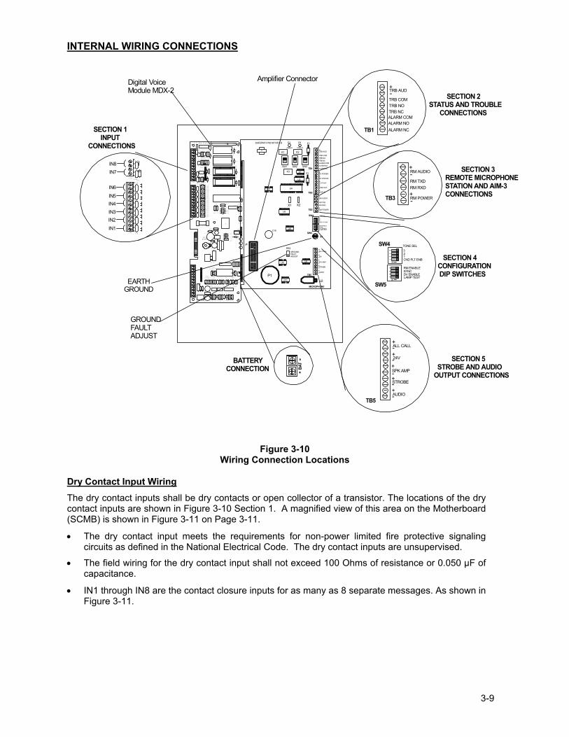
Figure 3-10
Wiring Connection Locations
Dry Contact Input Wiring The dry contact inputs shall be dry contacts or open collector of a transistor. The locations of the dry contact inputs are shown in Figure 3-10 Section 1. A magnified view of this area on the Motherboard (SCMB) is shown in Figure 3-11 on Page 3-11.
• The dry contact input meets the requirements for non-power limited fire protective signaling circuits as defined in the National Electrical Code. The dry contact inputs are unsupervised.
• The field wiring for the dry contact input shall not exceed 100 Ohms of resistance or 0.050 µF of capacitance.
• IN1 through IN8 are the contact closure inputs for as many as 8 separate messages. As shown in Figure 3-11.
3-10
IN8IN7
IN6
IN5IN4IN3IN2IN1
TB2 RV1
TB3
RV8
RV5
D11RV7
RV6
RV3
RV4
RV2
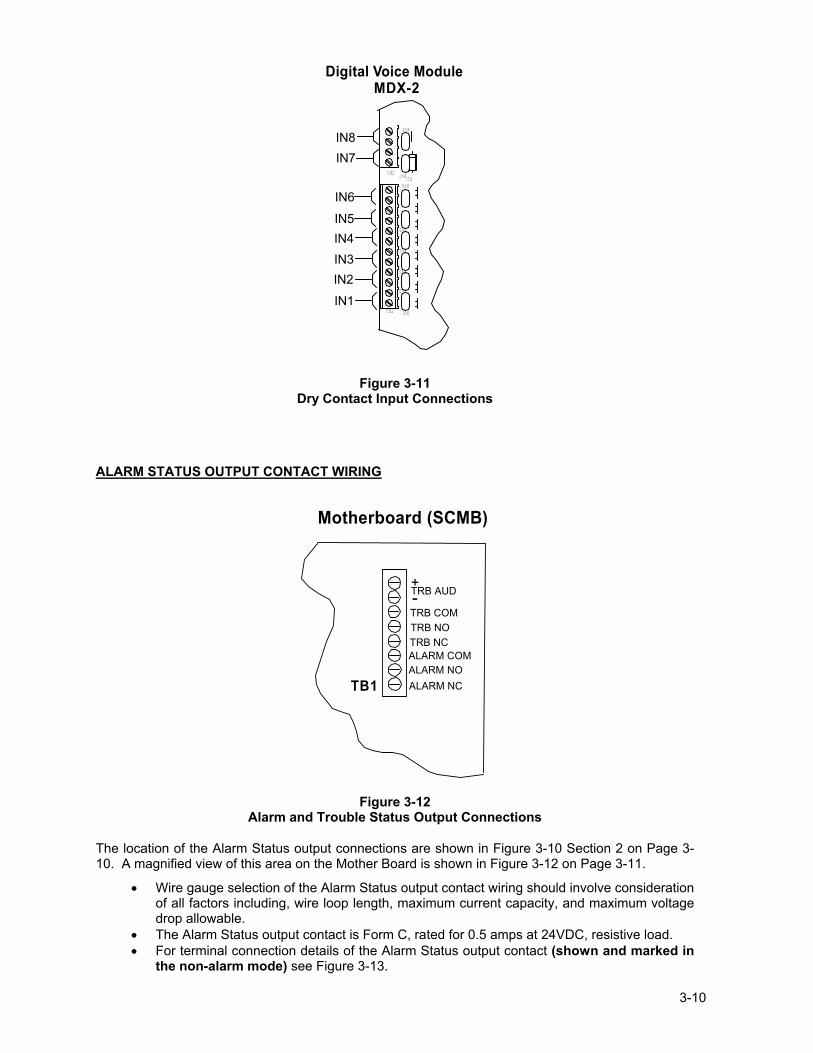
Digital Voice Module MDX-2
Figure 3-11 Dry Contact Input Connections
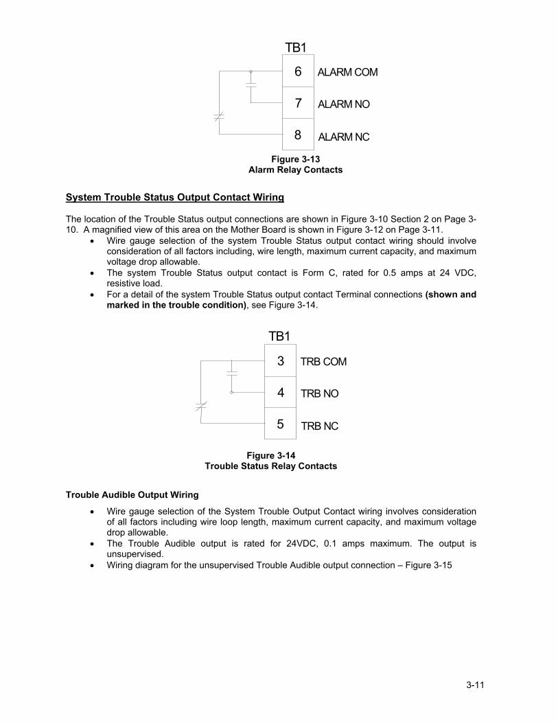
ALARM STATUS OUTPUT CONTACT WIRING
TB1
TRB AUD
TRB COMTRB NOTRB NCALARM COMALARM NOALARM NC
+-
Motherboard (SCMB)
Figure 3-12
Alarm and Trouble Status Output Connections
The location of the Alarm Status output connections are shown in Figure 3-10 Section 2 on Page 3-10. A magnified view of this area on the Mother Board is shown in Figure 3-12 on Page 3-11.
• Wire gauge selection of the Alarm Status output contact wiring should involve consideration of all factors including, wire loop length, maximum current capacity, and maximum voltage drop allowable.
• The Alarm Status output contact is Form C, rated for 0.5 amps at 24VDC, resistive load. • For terminal connection details of the Alarm Status output contact (shown and marked in
the non-alarm mode) see Figure 3-13.
3-11
ALARM COM
ALARM NO
ALARM NC
6
7
8
TB1
Figure 3-13
Alarm Relay Contacts
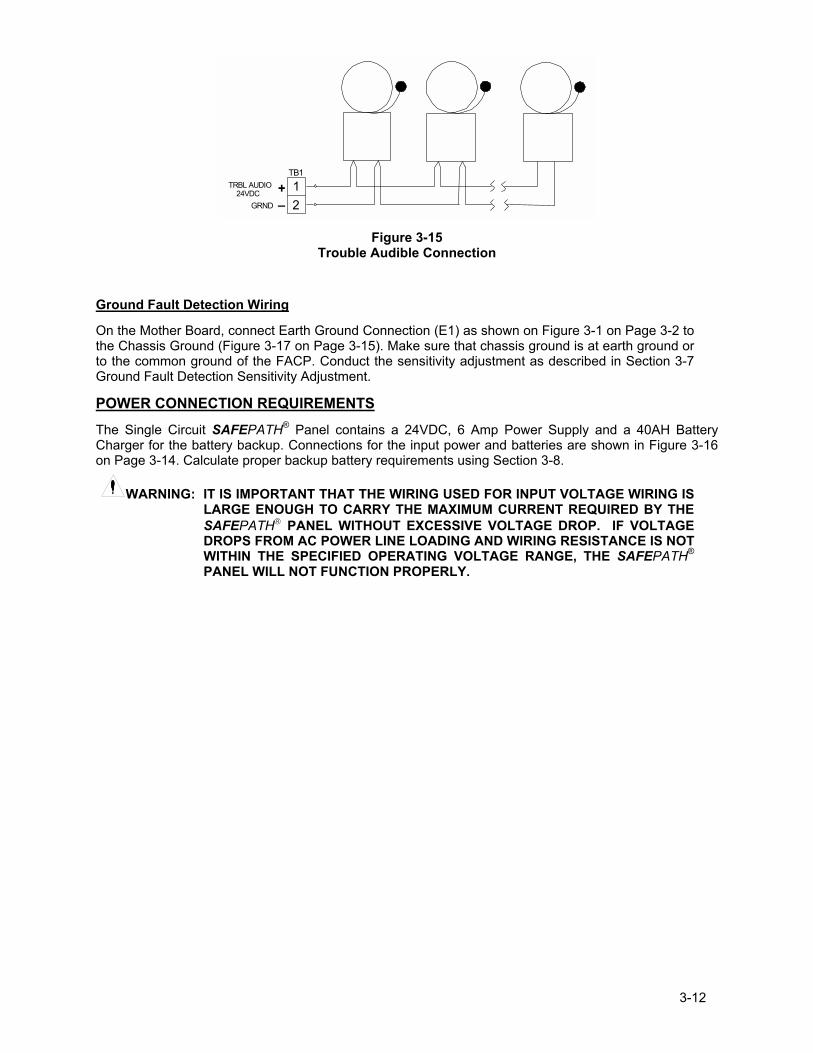
System Trouble Status Output Contact Wiring
The location of the Trouble Status output connections are shown in Figure 3-10 Section 2 on Page 3-10. A magnified view of this area on the Mother Board is shown in Figure 3-12 on Page 3-11.
• Wire gauge selection of the system Trouble Status output contact wiring should involve consideration of all factors including, wire length, maximum current capacity, and maximum voltage drop allowable.
• The system Trouble Status output contact is Form C, rated for 0.5 amps at 24 VDC, resistive load.
• For a detail of the system Trouble Status output contact Terminal connections (shown and marked in the trouble condition), see Figure 3-14.
TRB COM
TRB NO
TRB NC
3
4
5
TB1
Figure 3-14
Trouble Status Relay Contacts
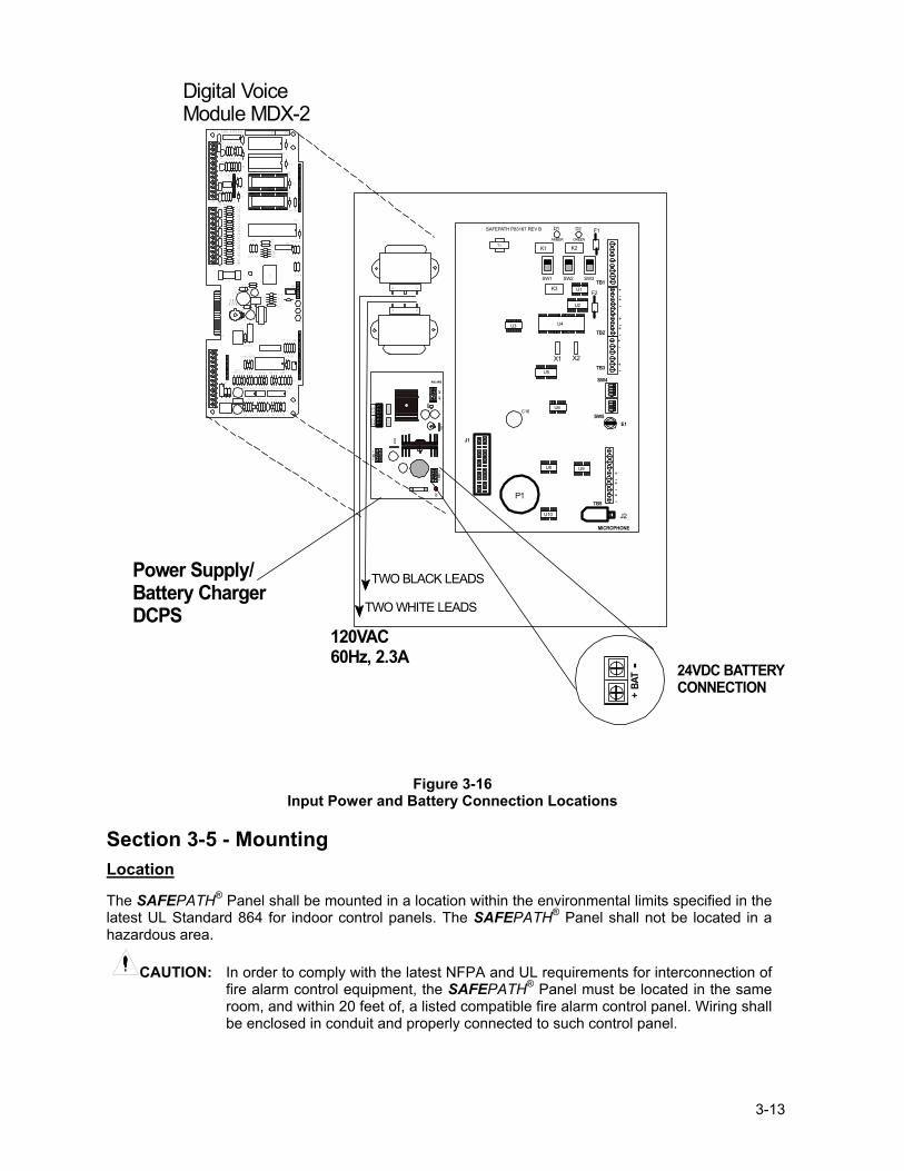
Trouble Audible Output Wiring
• Wire gauge selection of the System Trouble Output Contact wiring involves consideration of all factors including wire loop length, maximum current capacity, and maximum voltage drop allowable.
• The Trouble Audible output is rated for 24VDC, 0.1 amps maximum. The output is unsupervised.
• Wiring diagram for the unsupervised Trouble Audible output connection � Figure 3-15
3-12
12
TB1TRBL AUDIO 24VDC
GRND
+_
Figure 3-15
Trouble Audible Connection
Ground Fault Detection Wiring
On the Mother Board, connect Earth Ground Connection (E1) as shown on Figure 3-1 on Page 3-2 to the Chassis Ground (Figure 3-17 on Page 3-15). Make sure that chassis ground is at earth ground or to the common ground of the FACP. Conduct the sensitivity adjustment as described in Section 3-7 Ground Fault Detection Sensitivity Adjustment.
POWER CONNECTION REQUIREMENTS
The Single Circuit SAFEPATH® Panel contains a 24VDC, 6 Amp Power Supply and a 40AH Battery Charger for the battery backup. Connections for the input power and batteries are shown in Figure 3-16 on Page 3-14. Calculate proper backup battery requirements using Section 3-8.
WARNING: IT IS IMPORTANT THAT THE WIRING USED FOR INPUT VOLTAGE WIRING IS LARGE ENOUGH TO CARRY THE MAXIMUM CURRENT REQUIRED BY THE SAFEPATH PANEL WITHOUT EXCESSIVE VOLTAGE DROP. IF VOLTAGE DROPS FROM AC POWER LINE LOADING AND WIRING RESISTANCE IS NOT WITHIN THE SPECIFIED OPERATING VOLTAGE RANGE, THE SAFEPATH® PANEL WILL NOT FUNCTION PROPERLY.
3-13
106
10 6
Digital VoiceModule MDX-2
S15
S14
S12
CH1 VOL
P83412 REV ( )
EARTHGND
REV:SN:
TB2
R46
RV1
C33
D13
D12
R59R60
R57R58
R55R56
R53R54
R51R52
R49R50
R47R48
R62
U17
U13
C48
C41
C40
C39
C38
C36
C35
C34
TB3
RV8
R72
RV9
RV10
R69
R68Q1
R73
Q2
RV5
R64 R63D11RV7
RV6
RV3
RV4
RV2
J5
J6
R65
U14
C43
C44
R71
U16C50
C49C47
U15
R66
R67
R70
C46
C45
U11
C42
C32
U12
D10
R41
R40
C30
C31
C29C28
R43
R44 R42
U10
R61
C37
R39
R38
C9
E1
F1
K1
R45
D3
J3
TB1
J2
C10 D2 D1
C8 R9 R2R5R7 R1C4 C2C7 C5
R32
K2
J1
D4
U8
C23
U7C27
C24C25
R34R35
D9
L2
U9
C26
L1
C21
D8R33
C22
J4
R36R37
D5
D7
D6
R28
R23
R10
R19 R13
R21R22 R14R17C17 C14 C12
U5
U6
C20
C19R26 R25 R30
R31 R29
R24C18
R16U3U4
C16R20 R18 C15
R8U1 R6C6
U2C11R15 C13 R11R12
R3R4 C3 C1
R27
+
+
+
+
+
S8
12
34
ON
12
34
ON
J1
MICROPHONE
TB5
E1SW5
SW4
TB3
TB2
TB1SW1 SW2 SW3
K1 K2
K3
F1
F2
X1 X2
J2
P1
C16
D1 D2
U1
U2
U3 U4
U5
U6
U8 U9
U10
+-
+-+-
+-
+-+-
T1
+-
+-
+-
SAFEPATH P83167 REV B
AMBER GREEN
DCBA
T+
-SW
1
AC
ACAC
+-
DC
SW2
BAT
FAIL
NO N
C C
AC
FAI
LC
NC
NO
SMP7PM
Power Supply/Battery ChargerDCPS
BAT
+-
TWO BLACK LEADS
TWO WHITE LEADS
120VAC60Hz, 2.3A
24VDC BATTERYCONNECTION
Figure 3-16 Input Power and Battery Connection Locations
Section 3-5 - Mounting Location The SAFEPATH® Panel shall be mounted in a location within the environmental limits specified in the latest UL Standard 864 for indoor control panels. The SAFEPATH® Panel shall not be located in a hazardous area.
CAUTION: In order to comply with the latest NFPA and UL requirements for interconnection of fire alarm control equipment, the SAFEPATH® Panel must be located in the same room, and within 20 feet of, a listed compatible fire alarm control panel. Wiring shall be enclosed in conduit and properly connected to such control panel.
3-14
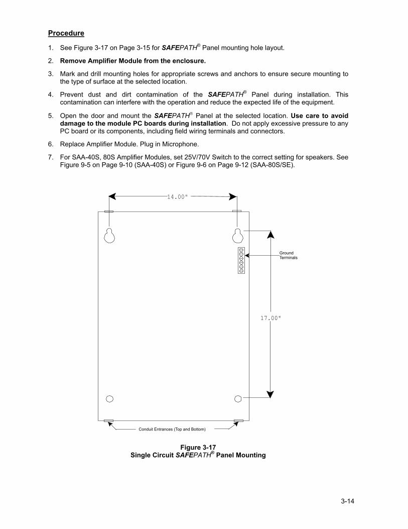
Procedure
1. See Figure 3-17 on Page 3-15 for SAFEPATH® Panel mounting hole layout.
2. Remove Amplifier Module from the enclosure.
3. Mark and drill mounting holes for appropriate screws and anchors to ensure secure mounting to the type of surface at the selected location.
4. Prevent dust and dirt contamination of the SAFEPATH® Panel during installation. This contamination can interfere with the operation and reduce the expected life of the equipment.
5. Open the door and mount the SAFEPATH Panel at the selected location. Use care to avoid damage to the module PC boards during installation. Do not apply excessive pressure to any PC board or its components, including field wiring terminals and connectors.
6. Replace Amplifier Module. Plug in Microphone.
7. For SAA-40S, 80S Amplifier Modules, set 25V/70V Switch to the correct setting for speakers. See Figure 9-5 on Page 9-10 (SAA-40S) or Figure 9-6 on Page 9-12 (SAA-80S/SE).
17.00"
14.00"
Conduit Entrances (Top and Bottom)
GroundTerminals
Figure 3-17
Single Circuit SAFEPATH® Panel Mounting
3-15
Section 3-6 System Checkout Refer to NFPA 72 (1999 Edition) for guidelines on testing notification systems.
CAUTION: If a malfunction, or system trouble occurs during testing, STOP TESTING. Correct the problem before you resume testing.
Insure that speaker and strobe NAC Circuits are not connected to the SAFEPATH® Panel, and that 10K Ohm ¼W EOLR test resistors are connected in their place on the Mother Board.
1. Place switches on the Single Circuit Motherboard (SCMB) (Figure 3-10, Section 4 on Page 3-10
or Figure 3-18 on Page 3-17 for enlarged view) as follows:
DIP Switch SW4: TONE SEL, 3 � OFF, 2 � ON, 1 � ON, GND FLT ENB � OFF
DIP Switch SW5: RM ENABLE � OFF, SYNC � ON, DV ENABLE � ON, LAMP TEST - OFF
AUTOMATIC /MANUAL Switch: UP or �AUTOMATIC� position.
CAUTION: Connect the AC power source before connecting the battery backup power. Disconnect the battery backup power before disconnecting the AC power source.
2. Connect AC Power, then connect battery backup.
The green System Normal LED indicator on the Motherboard should be �ON� to indicate normal operation. If the amber system trouble LED is �ON�, a trouble condition is indicated. Refer to Chapter 7 "Troubleshooting and Servicing" to diagnose and correct the trouble condition. Initial Checkout 3. With both AC Power and battery backup power applied observe the following indicators: Single Circuit Motherboard (SCMB) (See Figure 9-2 ) TROUBLE / NORMAL LEDs Yellow �OFF�, Green �ON� Digital Voice Module (MDX-2) (See Figure 9-3) LED D5 (Green) �ON� LED D6 (Yellow) �OFF� LED D7 (Yellow) �OFF� Amplifiers (SAA-40S, SAA-80S/SE, SALL-15S) SAA-40S, SAA-80S/SE (See Figure 9-5 for SAA-40S or Figure 9-6 for SAA-80S/SE) LED D15 (STR) �OFF� LED D10 (SPK) �OFF� LED D6 (AMP) �OFF�. SALL-15S (See Figure 9-7) LED D16 (STROBE) �OFF� LED D13 (AUDIO) �OFF� LED D10 (PWR) �OFF� LED D3 (AMP) �OFF�. 4. Play first message by momentarily shorting IN1 on the Digital Voice Module (MDX-2). Relay on
SCMB clicks at 1 click per second. When message ends, relay will stop clicking. Amplifier Modules: All LEDs �OFF�.
5. Key Microphone in panel. Relay on SCMB clicks at 1 click per second. When microphone push to
talk (PTT) is released, clicking will continue until the RESET Switch is depressed (See Figure 5-1 on Page 5-3 for location). Amplifier Modules: All LEDs �OFF�.
6. Disconnect Battery Backup, then disconnect AC Power. 7. Return to Section 3-2 General Installation Instructions, Step 13.
3-16
Final Checkout
CAUTION: If a malfunction, or system trouble occurs during testing, STOP TESTING. Correct the problem before you resume testing.
CAUTION: Connect the AC power source before connecting the battery backup power.
Disconnect the battery backup power before disconnecting the AC power source.
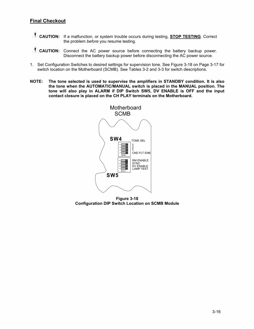
1. Set Configuration Switches to desired settings for supervision tone. See Figure 3-18 on Page 3-17 for switch location on the Motherboard (SCMB). See Tables 3-2 and 3-3 for switch descriptions.
NOTE: The tone selected is used to supervise the amplifiers in STANDBY condition. It is also
the tone when the AUTOMATIC/MANUAL switch is placed in the MANUAL position. The tone will also play in ALARM if DIP Switch SW5, DV ENABLE is OFF and the input contact closure is placed on the CH PLAY terminals on the Motherboard.
12
34
O N
12
34
O N
SW5
SW4 TONE SEL321CND FLT ENB
RM ENABLESYNCDV ENABLELAMP TEST
Motherboard SCMB
Figure 3-18
Configuration DIP Switch Location on SCMB Module
3-17
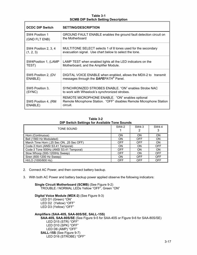
Table 3-1 SCMB DIP Switch Setting Description
DCDC DIP Switch SETTING/DESCRIPTION
SW4 Position 1 (GND FLT ENB)
GROUND FAULT ENABLE enables the ground fault detection circuit on the Motherboard
SW4 Position 2, 3, 4 (1, 2, 3)
MULTITONE SELECT selects 1 of 8 tones used for the secondary evacuation signal. Use chart below to select the tone.
SW4Position 1, (LAMP TEST)
LAMP TEST when enabled lights all the LED indicators on the Motherboard, and the Amplifier Module.
SW5 Position 2, (DV ENABLE)
DIGITAL VOICE ENABLE when enabled, allows the MDX-2 to transmit messages through the SAFEPATH® Panel.
SW5 Position 3, (SYNC)
SYNCHRONIZED STROBES ENABLE. �ON� enables Strobe NAC to work with Wheelock�s synchronized strobes.
SW5 Position 4, (RM ENABLE)
REMOTE MICROPHONE ENABLE. �ON� enables optional Remote Microphone Station. �OFF� disables Remote Microphone Station circuit.
Table 3-2 DIP Switch Settings for Available Tone Sounds
TONE SOUND SW4-2 1
SW4-3 2
SW4-4 3
Horn (Continuous) ON ON ON Bell (1560 Hz Modulated) ON OFF ON March Time Horn (.25 Sec ON, .25 Sec OFF) OFF OFF ON Code-3 Horn (ANSI S3.41 Temporal) ON ON OFF Code-3 Tone 500Hz (ANSI S3.41 Temporal) OFF ON ON Slow Whoop (500-1200Hz Sweep) OFF ON OFF Siren (600-1200 Hz Sweep) ON OFF OFF HI/LO (1000/800 Hz) OFF OFF OFF
2. Connect AC Power, and then connect battery backup. 3. With both AC Power and battery backup power applied observe the following indicators:
Single Circuit Motherboard (SCMB) (See Figure 9-2) TROUBLE / NORMAL LEDs Yellow �OFF�, Green �ON� Digital Voice Module (MDX-2) (See Figure 9-3) LED D1 (Green) �ON� LED D2 (Yellow) �OFF� LED D3 (Yellow) �OFF�
Amplifiers (SAA-40S, SAA-80S/SE, SALL-15S) SAA-40S, SAA-80S/SE (See Figure 9-5 for SAA-40S or Figure 9-6 for SAA-80S/SE) LED D15 (STR) �OFF� LED D10 (SPK) �OFF� LED D6 (AMP) �OFF� SALL-15S (See Figure 9-7) LED D16 (STROBE) �OFF�
3-18
LED D13 (AUDIO) �OFF� LED D10 (PWR) �OFF� LED D3 (AMP) �OFF� 4. Play each messages by momentarily shorting IN1 through IN8 in turn on Digital Voice Module.
See Figure 3-11 on Page 3-11.
Relay on SCMB clicks at 1 click per second during the playing of each message. Message will broadcast on all appliance circuits. If Strobe NAC circuits are in use, Strobes will also flash.
5. Key Microphone in panel.
Relay closure can be heard.
Message will broadcast on all appliance circuits. If Strobe NAC circuits are in use, Strobes will also flash.
6. If Remote Microphone Station (RMS-2) or the AIM-3 is included, enable it by switching SW5-4 (RM ENABLE) to �ON� on the Single Circuit Motherboard (SCMB).
7. Test the Remote Microphone Station. 8. System is fully operational.
Additional system checkout should include:
Testing all Alarm and Trouble circuits. Testing all connections to equipment that is interconnected with the SAFEPATH® Panel.
WARNING: ALL PROTECTIVE SIGNALING SYSTEMS REQUIRE PERIODIC TESTING. ALL PROTECTIVE SIGNALING SYSTEM EQUIPMENT SHALL BE TESTED BY QUALIFIED PERSONNEL AT LEAST TWICE A YEAR FOR PROPER OPERATION, OR MORE OFTEN IF REQUIRED BY CODES, REGULATIONS AND LAWS. FAILURE TO MAINTAIN AND TEST PROTECTIVE SIGNALING SYSTEM EQUIPMENT CAN RESULT IN NOT DETECTING EQUIPMENT FAILURE THAT CAN CAUSE PROPERTY DAMAGE AND SERIOUS PERSONAL INJURY OR DEATH TO YOU AND/OR OTHERS DURING AN EMERGENCY SITUATION.
Section 3-7 � Ground Fault Detection Sensitivity Adjustment Ground fault detection sensitivity can be adjusted for a set point between 40K Ohms and 500K Ohms.
Selecting a high resistance set point will increase the circuit sensitivity to ground fault conditions. A high resistance may cause many false trouble conditions.
Selecting a low resistance will decrease the circuit sensitivity and will greatly reduce susceptibility to false trouble conditions. The lower resistance allows for lower ground fault resistance before a ground fault conditions occurs.
Before the sensitivity is adjusted, it is imperative to correct (clear) all trouble conditions.
NOTE: The ground fault detection sensitivity set-point shall be the same value as the FACP.
Adjustment Procedure
1. Place "GRND FLT ENB DIP switch in the ON position (SW4, POS 1). See Figure 3-18 on Page 3-17.
2. Disconnect the wire between earth ground and the earth ground terminal on the Mother Board. (See Figure 9-2 on Page 9-5 for location.)
3-19
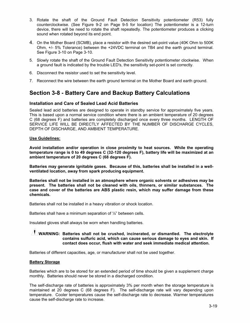
3. Rotate the shaft of the Ground Fault Detection Sensitivity potentiometer (R53) fully counterclockwise. (See Figure 9-2 on Page 9-5 for location) The potentiometer is a 12-turn device, there will be need to rotate the shaft repeatedly. The potentiometer produces a clicking sound when rotated beyond its end point.
4. On the Mother Board (SCMB), place a resistor with the desired set-point value (40K Ohm to 500K Ohm, +/- 5% Tolerance) between the +24VDC terminal on TB4 and the earth ground terminal. See Figure 3-10 on Page 3-10.
5. Slowly rotate the shaft of the Ground Fault Detection Sensitivity potentiometer clockwise. When a ground fault is indicated by the trouble LED's, the sensitivity set-point is set correctly.
6. Disconnect the resistor used to set the sensitivity level.
7. Reconnect the wire between the earth ground terminal on the Mother Board and earth ground. Section 3-8 - Battery Care and Backup Battery Calculations Installation and Care of Sealed Lead Acid Batteries
Sealed lead acid batteries are designed to operate in standby service for approximately five years. This is based upon a normal service condition where there is an ambient temperature of 20 degrees C (68 degrees F) and batteries are completely discharged once every three months. LENGTH OF SERVICE LIFE WILL BE DIRECTLY AFFECTED BY THE NUMBER OF DISCHARGE CYCLES, DEPTH OF DISCHARGE, AND AMBIENT TEMPERATURE. Use Guidelines: Avoid installation and/or operation in close proximity to heat sources. While the operating temperature range is 0 to 49 degrees C (32-120 degrees F), battery life will be maximized at an ambient temperature of 20 degrees C (68 degrees F). Batteries may generate ignitable gases. Because of this, batteries shall be installed in a well-ventilated location, away from spark producing equipment. Batteries shall not be installed in an atmosphere where organic solvents or adhesives may be present. The batteries shall not be cleaned with oils, thinners, or similar substances. The case and cover of the batteries are ABS plastic resin, which may suffer damage from these chemicals. Batteries shall not be installed in a heavy vibration or shock location. Batteries shall have a minimum separation of ¼� between cells. Insulated gloves shall always be worn when handling batteries.
WARNING: Batteries shall not be crushed, incinerated, or dismantled. The electrolyte contains sulfuric acid, which can cause serious damage to eyes and skin. If contact does occur, flush with water and seek immediate medical attention.
Batteries of different capacities, age, or manufacturer shall not be used together. Battery Storage Batteries which are to be stored for an extended period of time should be given a supplement charge monthly. Batteries should never be stored in a discharged condition. The self-discharge rate of batteries is approximately 3% per month when the storage temperature is maintained at 20 degrees C (68 degrees F). The self-discharge rate will vary depending upon temperature. Cooler temperatures cause the self-discharge rate to decrease. Warmer temperatures cause the self-discharge rate to increase.
3-20
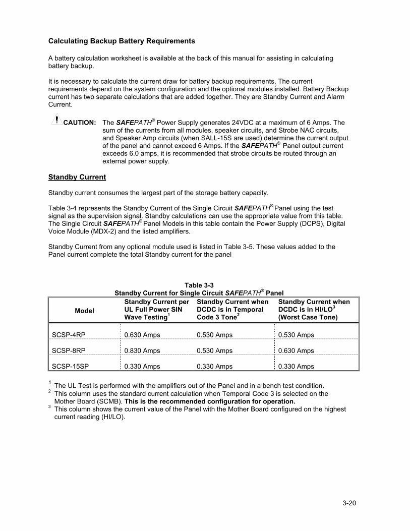
Calculating Backup Battery Requirements A battery calculation worksheet is available at the back of this manual for assisting in calculating battery backup. It is necessary to calculate the current draw for battery backup requirements, The current requirements depend on the system configuration and the optional modules installed. Battery Backup current has two separate calculations that are added together. They are Standby Current and Alarm Current.
CAUTION: The SAFEPATH® Power Supply generates 24VDC at a maximum of 6 Amps. The sum of the currents from all modules, speaker circuits, and Strobe NAC circuits, and Speaker Amp circuits (when SALL-15S are used) determine the current output of the panel and cannot exceed 6 Amps. If the SAFEPATH® Panel output current exceeds 6.0 amps, it is recommended that strobe circuits be routed through an external power supply.
Standby Current Standby current consumes the largest part of the storage battery capacity. Table 3-4 represents the Standby Current of the Single Circuit SAFEPATH® Panel using the test signal as the supervision signal. Standby calculations can use the appropriate value from this table. The Single Circuit SAFEPATH® Panel Models in this table contain the Power Supply (DCPS), Digital Voice Module (MDX-2) and the listed amplifiers. Standby Current from any optional module used is listed in Table 3-5. These values added to the Panel current complete the total Standby current for the panel
Table 3-3 Standby Current for Single Circuit SAFEPATH® Panel
Model
Standby Current per UL Full Power SIN Wave Testing1
Standby Current when DCDC is in Temporal Code 3 Tone2
Standby Current when DCDC is in HI/LO3 (Worst Case Tone)
SCSP-4RP
0.630 Amps
0.530 Amps
0.530 Amps
SCSP-8RP
0.830 Amps
0.530 Amps
0.630 Amps
SCSP-15SP
0.330 Amps
0.330 Amps
0.330 Amps
1 The UL Test is performed with the amplifiers out of the Panel and in a bench test condition. 2 This column uses the standard current calculation when Temporal Code 3 is selected on the
Mother Board (SCMB). This is the recommended configuration for operation. 3 This column shows the current value of the Panel with the Mother Board configured on the highest
current reading (HI/LO).
3-21
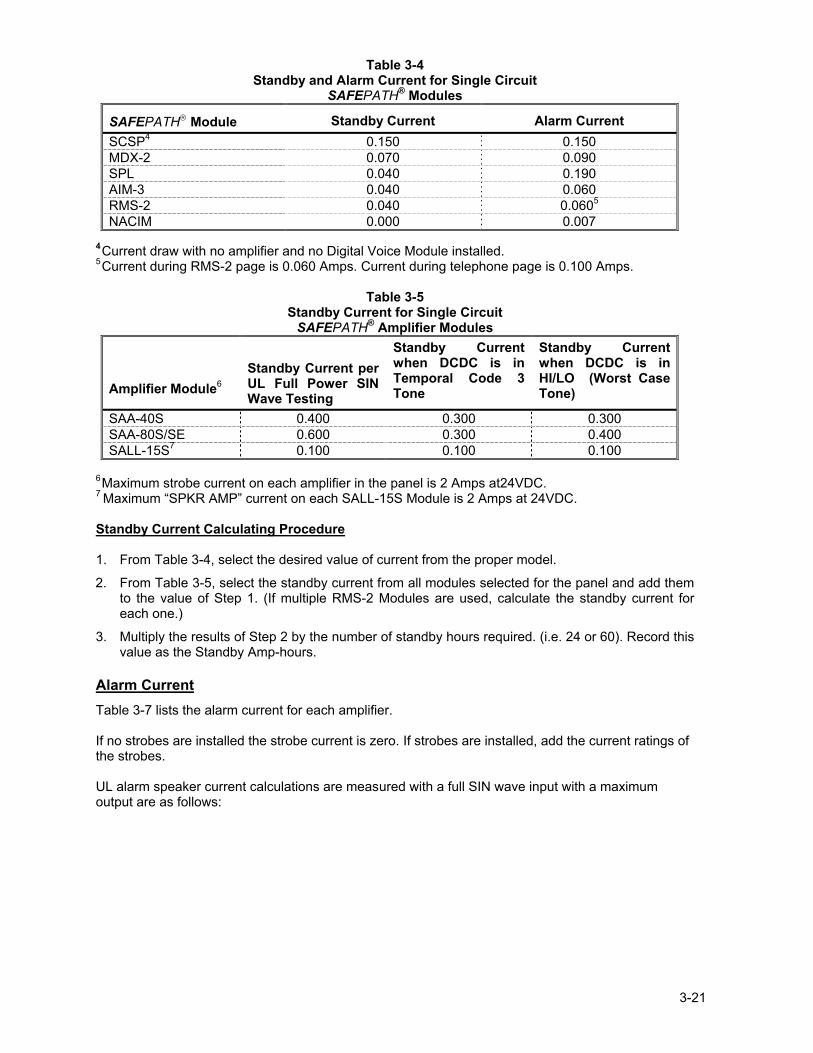
Table 3-4 Standby and Alarm Current for Single Circuit
SAFEPATH® Modules
SAFEPATH Module Standby Current Alarm Current SCSP4 0.150 0.150
MDX-2 0.070 0.090 SPL 0.040 0.190 AIM-3 0.040 0.060
RMS-2 0.040 0.0605
NACIM 0.000 0.007 4 Current draw with no amplifier and no Digital Voice Module installed. 5 Current during RMS-2 page is 0.060 Amps. Current during telephone page is 0.100 Amps.
Table 3-5 Standby Current for Single Circuit SAFEPATH® Amplifier Modules
Amplifier Module6
Standby Current per UL Full Power SIN Wave Testing
Standby Current when DCDC is in Temporal Code 3 Tone
Standby Current when DCDC is in HI/LO (Worst Case Tone)
SAA-40S 0.400 0.300 0.300 SAA-80S/SE 0.600 0.300 0.400 SALL-15S7 0.100 0.100 0.100
6 Maximum strobe current on each amplifier in the panel is 2 Amps at24VDC. 7 Maximum �SPKR AMP� current on each SALL-15S Module is 2 Amps at 24VDC. Standby Current Calculating Procedure 1. From Table 3-4, select the desired value of current from the proper model.
2. From Table 3-5, select the standby current from all modules selected for the panel and add them to the value of Step 1. (If multiple RMS-2 Modules are used, calculate the standby current for each one.)
3. Multiply the results of Step 2 by the number of standby hours required. (i.e. 24 or 60). Record this value as the Standby Amp-hours.
Alarm Current Table 3-7 lists the alarm current for each amplifier. If no strobes are installed the strobe current is zero. If strobes are installed, add the current ratings of the strobes. UL alarm speaker current calculations are measured with a full SIN wave input with a maximum output are as follows:
3-22
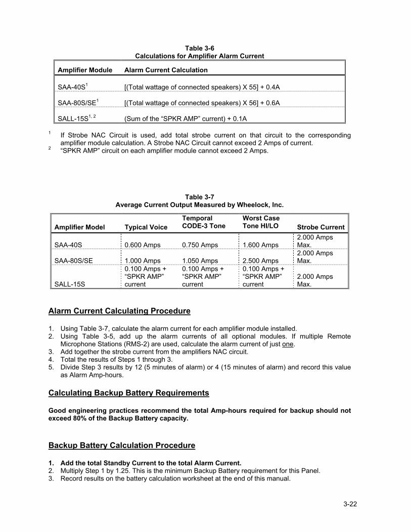
Table 3-6 Calculations for Amplifier Alarm Current
Amplifier Module
Alarm Current Calculation SAA-40S1
[(Total wattage of connected speakers) X 55] + 0.4A
SAA-80S/SE1
[(Total wattage of connected speakers) X 56] + 0.6A
SALL-15S1, 2
(Sum of the �SPKR AMP� current) + 0.1A
1 If Strobe NAC Circuit is used, add total strobe current on that circuit to the corresponding
amplifier module calculation. A Strobe NAC Circuit cannot exceed 2 Amps of current. 2 �SPKR AMP� circuit on each amplifier module cannot exceed 2 Amps.
Table 3-7 Average Current Output Measured by Wheelock, Inc.
Amplifier Model
Typical Voice
Temporal CODE-3 Tone
Worst Case Tone HI/LO
Strobe Current
SAA-40S
0.600 Amps
0.750 Amps
1.600 Amps
2.000 Amps Max.
SAA-80S/SE
1.000 Amps
1.050 Amps
2.500 Amps
2.000 Amps Max.
SALL-15S
0.100 Amps + �SPKR AMP� current
0.100 Amps + �SPKR AMP� current
0.100 Amps + �SPKR AMP� current
2.000 Amps Max.
Alarm Current Calculating Procedure 1. Using Table 3-7, calculate the alarm current for each amplifier module installed. 2. Using Table 3-5, add up the alarm currents of all optional modules. If multiple Remote
Microphone Stations (RMS-2) are used, calculate the alarm current of just one. 3. Add together the strobe current from the amplifiers NAC circuit. 4. Total the results of Steps 1 through 3. 5. Divide Step 3 results by 12 (5 minutes of alarm) or 4 (15 minutes of alarm) and record this value
as Alarm Amp-hours. Calculating Backup Battery Requirements Good engineering practices recommend the total Amp-hours required for backup should not exceed 80% of the Backup Battery capacity. Backup Battery Calculation Procedure 1. Add the total Standby Current to the total Alarm Current. 2. Multiply Step 1 by 1.25. This is the minimum Backup Battery requirement for this Panel. 3. Record results on the battery calculation worksheet at the end of this manual.

3-23
4-1
Chapter 4 - OPERATION Section 4-1- Introduction This chapter describes the operating characteristics of the SAFEPATH® Panel. Included is information about the following SAFEPATH® Panel features:
• Operator's Console • Supervision • Visual Notification Appliance Output Circuit Supervision • Audio Notification Appliance Output Circuit Supervision • Amplified Speaker Notification Appliance Power Output Supervision • Amplifier Supervision • Remote Microphone Station Supervision (Optional RMS-3) • Actions that Initiate Alarms
Section 4-2 - Operator�s Console An operator�s console, which allows for manual override of the automatic message playing, is provided. The operator�s console includes a microphone, a RESET pushbutton, a TROUBLE ACKNOWLEDGE pushbutton, and a main AUTOMATIC/MANUAL switch. There are two LEDs to indicate NORMAL for normal operation and TROUBLE for any Panel trouble condition. Opening the enclosure door accesses the operator�s console. Section 4-3 - Supervision A trouble condition indicates that the supervisory functions have detected a malfunction in the panel. When a trouble condition is detected, the panel may not be able to receive and/or remember message requests from the control panel. The installer and/or user must make sure that any message requests to the panel during a trouble condition are reactivated if necessary, when the panel is returned to normal. If a trouble condition is detected by any of the supervisory functions, the panel Form C status relay (normally energized) will change state, the green NORMAL LED will turn �OFF�, and the amber TROUBLE LED will turn �ON�. The status relay contact closure must be properly connected to and used by the control panel to indicate a system trouble. At the same time an amber trouble location LED will identify the location of the trouble condition. If a trouble condition is indicated, follow the procedures in Chapter 7 "Troubleshooting�.
WARNING: DO NOT LEAVE THE PANEL IN A TROUBLE CONDITION AS, IT MAY NOT PLAY WARNING MESSAGES WHICH COULD RESULT IN PROPERTY DAMAGE AND SERIOUS INJURY OR DEATH TO YOU AND/OR OTHERS. IF THE PANEL INDICATES A TROUBLE CONDITION:
(1) PROVIDE UL REQUIRED ALTERNATIVE SIGNALING AND (2) HAVE QUALIFIED SERVICE PERSONS IMMEDIATELY REPLACE
UNIT(S) THAT HAVE MALFUNCTIONED.
4-2
WARNING: MESSAGES REQUESTED BEFORE AND DURING A TROUBLE CONDITION MAY
NOT BE HEARD, WHICH COULD RESULT IN PROPERTY DAMAGE AND SERIOUS INJURY OR DEATH TO YOU AND/OR OTHERS. IF MESSAGES REQUESTED BEFORE AND DURING A TROUBLE CONDITION ARE STILL NECESSARY, THEY SHOULD BE REPEATED WHEN THE SAFEPATH® PANEL IS RETURNED TO NORMAL.
Visual Notification Appliance Output Circuit Supervision The visual notification appliance output circuit is supervised for open and short circuits when the output is de-energized. Output circuit supervision requires installation of the supplied UL LISTED, 10K Ohm EOLR on the output circuit. Any sensed trouble will illuminate the �STR� LED on the amplifier module. See Figure 7-1 on Page 7-2 for LED location.
Audio Notification Appliance Output Circuit Supervision The audio notification appliance output circuit is supervised for open and short circuits when the output is de-energized. The circuit is unsupervised when the output is energized. Output circuit supervision requires installation of the supplied UL LISTED, 10K Ohm EOLR on the output circuit. Any sensed trouble will illuminate the �SPK� LED on the amplifier module. See Figure 7-1 on Page 7-2 for LED location.
Amplified Speaker Notification Appliance Power Output Circuit Supervision The amplified speaker notification appliance power output circuit supervised for open and short circuits when the output is de-energized. Output circuit supervision requires installation of the supplied UL LISTED, 10K Ohm EOLR on the output circuit. Any sensed trouble will illuminate the �PWR� LED on the SALL-15S module. See Figure 7-1 on Page 7-2 for LED location.
Amplifier Supervision
A supervisory tone plays through the amplifier during standby for supervision purpose. Any sensed trouble illuminates the �AMP� LED on the amplifier module. See Figure 7-1 on Page 7-2 for LED location. Ground Fault Supervision The SAFEPATH® Panel supervises for ground fault conditions on field wiring that is not electrically isolated. The supervised wiring includes contact inputs, visual NAC circuits, audio NAC circuits, amplified speaker NAC circuits, trouble audible output circuits, remote microphone station wiring and MDX-2 wiring. All other wiring is electrically isolated. Ground fault supervision may be enabled and disabled by switching the ground fault enable switch on (GND FLT ENB, SW4, POS 1). See Figure 3-18 on Page 3-17.
Remote Microphone Supervision (Optional RMS-2) The audio circuit is supervised on the Remote Microphone Station PCB.
Section 4-4 - Actions That Initiate Alarms Table 4-1 indicates what can initiate an alarm condition and the resulting SAFEPATH Panel actions. NOTE: The list is arranged in order of priority (e.g., number 1 in Table 4-1 supersedes number 2
priority).
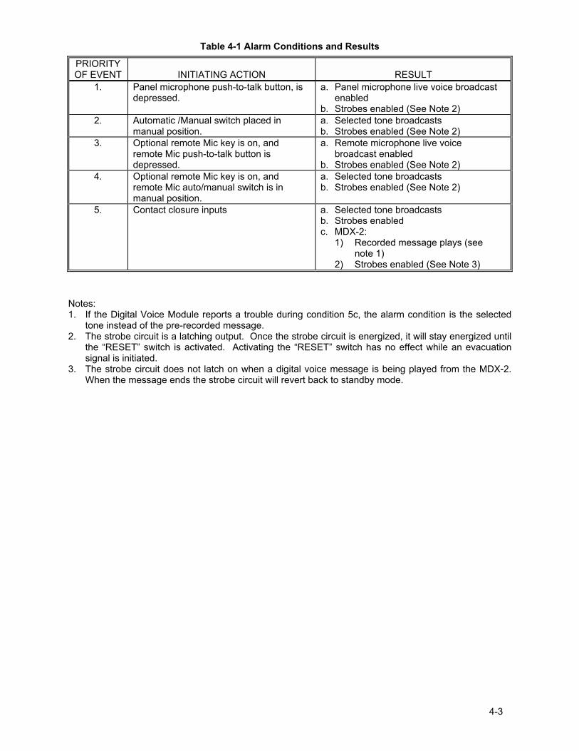
4-3
Table 4-1 Alarm Conditions and Results
PRIORITY OF EVENT
INITIATING ACTION
RESULT
1. Panel microphone push-to-talk button, is depressed.
a. Panel microphone live voice broadcast enabled b. Strobes enabled (See Note 2)
2. Automatic /Manual switch placed in manual position.
a. Selected tone broadcasts b. Strobes enabled (See Note 2)
3. Optional remote Mic key is on, and remote Mic push-to-talk button is depressed.
a. Remote microphone live voice broadcast enabled b. Strobes enabled (See Note 2)
4. Optional remote Mic key is on, and remote Mic auto/manual switch is in manual position.
a. Selected tone broadcasts b. Strobes enabled (See Note 2)
5. Contact closure inputs a. Selected tone broadcasts b. Strobes enabled c. MDX-2: 1) Recorded message plays (see note 1) 2) Strobes enabled (See Note 3)
Notes: 1. If the Digital Voice Module reports a trouble during condition 5c, the alarm condition is the selected
tone instead of the pre-recorded message. 2. The strobe circuit is a latching output. Once the strobe circuit is energized, it will stay energized until
the �RESET� switch is activated. Activating the �RESET� switch has no effect while an evacuation signal is initiated.
3. The strobe circuit does not latch on when a digital voice message is being played from the MDX-2. When the message ends the strobe circuit will revert back to standby mode.

4-4
Intentionally Blank
5-1
Chapter 5 - Operational Procedures Section 5-1 - Operator Instructions The SAFEPATH® Panel provides an operator console for manually activating the panel. The operator console includes a microphone, a green NORMAL LED, a yellow TROUBLE LED, a �RESET� momentary switch, a TROUBLE ACKNOWLEDGE momentary switch, and a MANUAL/AUTOMATIC switch. The operator interface allows the operator to manually override automatically playing pre-recorded messages with live announcements or an evacuation tone, to silence internal and external trouble audibles, and to ascertain if the panel has detected a trouble condition. The operator instructions on the dead front panel are shown in Figure 5-1 on Page 5-3. The TROUBLE and NORMAL LEDs identify to the operator the condition of the SAFEPATH® Panel. The yellow TROUBLE LED will be illuminated whenever there is a trouble detected by the Panel. If no troubles are detected, the green NORMAL LED will be illuminated. The TROUBLE ACKNOWLEDGE push-button allows the operator to silence the trouble audibles, both internal and external. When a trouble condition is detected, both the internal and external trouble audibles are sounded. When the ACKNOWLEDGE push-button is depressed, the internal and external trouble audibles will be silenced. The trouble audibles will resound for subsequent trouble conditions. The Form C trouble output contact will remain in the trouble condition and the TROUBLE LED will remain illuminated until all trouble conditions have been corrected. The AUTOMATIC/MANUAL switch has two positions, manual (down) and automatic (up). When the AUTOMATIC/MANUAL toggle switch is in the automatic position, pre-recorded messages may be selected to play via dry contact inputs. When the AUTOMATIC/MANUAL switch is in the manual position, pre-recorded messages will not play, the visual notification appliances are energized, and the evacuation tone sounds. Section 5-2 - To Make Live Announcements From Panel
1. Hold the microphone within 2 inches of your mouth, press the push-to-talk switch and begin speaking.
From Optional Remote Microphone Station (RMS-2)
1. Turn the key switch from the OFF position to the ON position.
2. Hold the microphone within 2 inches of your mouth, press the push-to-talk switch and begin speaking.
See the Remote Microphone Station instruction sheet P83270 for additional information.
Section 5-3 - To Sound Evacuation Tone
From Panel 1. Slide the AUTOMATIC/MANUAL switch on the panel down to the MANUAL position. The selected
tone will play. Turn off the tone by returning the AUTOMATIC/MANUAL Switch to the UP position. See Figure 5-1 on Page 5-3 for switch location.
From Optional Remote Microphone Station (RMS-2)
1. Turn the key switch from the �OFF� position to the �ON� position.
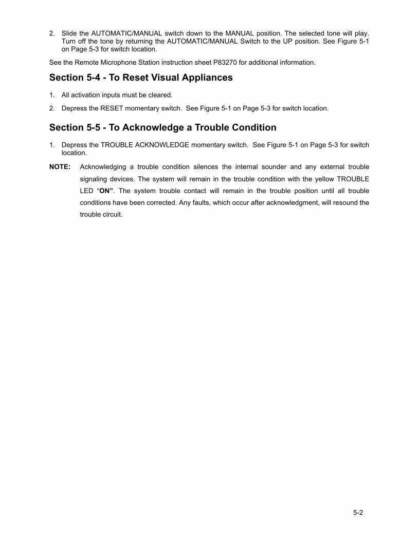
5-2
2. Slide the AUTOMATIC/MANUAL switch down to the MANUAL position. The selected tone will play. Turn off the tone by returning the AUTOMATIC/MANUAL Switch to the UP position. See Figure 5-1 on Page 5-3 for switch location.
See the Remote Microphone Station instruction sheet P83270 for additional information.
Section 5-4 - To Reset Visual Appliances 1. All activation inputs must be cleared.
2. Depress the RESET momentary switch. See Figure 5-1 on Page 5-3 for switch location.
Section 5-5 - To Acknowledge a Trouble Condition 1. Depress the TROUBLE ACKNOWLEDGE momentary switch. See Figure 5-1 on Page 5-3 for switch
location.
NOTE: Acknowledging a trouble condition silences the internal sounder and any external trouble
signaling devices. The system will remain in the trouble condition with the yellow TROUBLE
LED �ON�. The system trouble contact will remain in the trouble position until all trouble
conditions have been corrected. Any faults, which occur after acknowledgment, will resound the
trouble circuit.
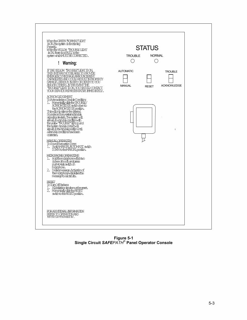
5-3
! Warning:
When the GREEN “NORMAL” LIGHT Is ON, the system is functioning Properly. When the YELLOW “TROUBLE LIGHT is ON, there is a FAULT in the system which MUST BE CORRECTED. IF THE YELLOW “TROUBLE” LIGHT IS ON, THIS UNIT MAY NOT BE ABLE TO PROVIDE EMERGENCY MESSAGE ANNOUNCEMENT CAPABILITIES AND COULD RESULT IN PROPERTY DAMAGE. SERIOUS INJURY OR DEATH TO YOU AND/OR OTHERS. IN THE EVENT THE “TROUBLE” LIGHT IS ON, YOU SHOULD CONTACT YOUR SERVICE REPRESENTATIVE IMMEDIATELY. ACKNOWLEDGEMENT To Acknowledge a Trouble Condition: 1. Momentarily slide the TROUBLE/
ACKNOWLEDGE switch down to the ACKNOWLEDGE position.
This will only silence the internal Sounder and any external trouble signaling devices. The system will remain in a trouble condition with the yellow “TROUBLE” light on and the system trouble contact will remain in the trouble position until all trouble conditions have been corrected. MANUAL OPERATION To Sound Evacuation Tone: 1. Switch MANUAL/AUTOMATIC switch
DOWN to the MANUAL position.
MICROPHONE OPERATIONS 1. Hold the microphone within two
inches of mouth and press push-to-talk switch on microphone.
2. Deliver message. Activation of the microphone will deliver the message to all circuits.
RESET To Turn Off Strobes: 1. All initiating circuits must be reset. 2. Momentarily slide the RESET
switch to the RESET position.
FOR ADDITIONAL INFORMATION REFER TO OPERATION AND INSTALLATIONMANUAL.
STATUSTROUBLE NORMAL
AUTOMATIC TROUBLE
MANUAL RESET ACKNOWLEDGE
Figure 5-1 Single Circuit SAFEPATH® Panel Operator Console

5-4
Intentionally Blank
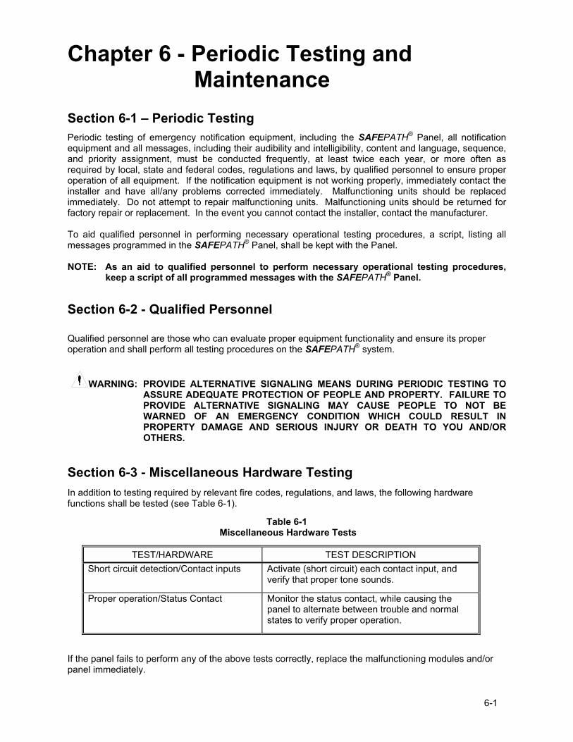
6-1
Chapter 6 - Periodic Testing and Maintenance
Section 6-1 � Periodic Testing
Periodic testing of emergency notification equipment, including the SAFEPATH® Panel, all notification equipment and all messages, including their audibility and intelligibility, content and language, sequence, and priority assignment, must be conducted frequently, at least twice each year, or more often as required by local, state and federal codes, regulations and laws, by qualified personnel to ensure proper operation of all equipment. If the notification equipment is not working properly, immediately contact the installer and have all/any problems corrected immediately. Malfunctioning units should be replaced immediately. Do not attempt to repair malfunctioning units. Malfunctioning units should be returned for factory repair or replacement. In the event you cannot contact the installer, contact the manufacturer.
To aid qualified personnel in performing necessary operational testing procedures, a script, listing all messages programmed in the SAFEPATH® Panel, shall be kept with the Panel.
NOTE: As an aid to qualified personnel to perform necessary operational testing procedures,
keep a script of all programmed messages with the SAFEPATH® Panel.
Section 6-2 - Qualified Personnel Qualified personnel are those who can evaluate proper equipment functionality and ensure its proper operation and shall perform all testing procedures on the SAFEPATH® system.
WARNING: PROVIDE ALTERNATIVE SIGNALING MEANS DURING PERIODIC TESTING TO
ASSURE ADEQUATE PROTECTION OF PEOPLE AND PROPERTY. FAILURE TO PROVIDE ALTERNATIVE SIGNALING MAY CAUSE PEOPLE TO NOT BE WARNED OF AN EMERGENCY CONDITION WHICH COULD RESULT IN PROPERTY DAMAGE AND SERIOUS INJURY OR DEATH TO YOU AND/OR OTHERS.
Section 6-3 - Miscellaneous Hardware Testing In addition to testing required by relevant fire codes, regulations, and laws, the following hardware functions shall be tested (see Table 6-1).
Table 6-1 Miscellaneous Hardware Tests
TEST/HARDWARE TEST DESCRIPTION Short circuit detection/Contact inputs Activate (short circuit) each contact input, and
verify that proper tone sounds.
Proper operation/Status Contact Monitor the status contact, while causing the panel to alternate between trouble and normal states to verify proper operation.
If the panel fails to perform any of the above tests correctly, replace the malfunctioning modules and/or panel immediately.

6-2
Intentionally Blank
7-1
Chapter 7 � Troubleshooting Section 7-1 - Troubleshooting
WARNING: SOME ELECTRONIC COMPONENTS STORE A HIGH VOLTAGE CHARGE, EVEN
THOUGH POWER IS NOT CONNECTED, AND CAN CAUSE A DANGEROUS SHOCK IF TOUCHED. DO NOT TOUCH EXPOSED CIRCUITRY ON THE SAFEPATH® PANEL UNLESS THE CIRCUITRY HAS DISCHARGED FOR ONE HOUR AND A SAFE DISCHARGE PROCEDURE IS USED.
WARNING: PROVIDE UL REQUIRED ALTERNATIVE SIGNALING MEANS DURING TROUBLE CONDITIONS AND SERVICING TO ASSURE ADEQUATE PROTECTION OF PEOPLE AND PROPERTY. HAVE QUALIFIED SERVICE PERSONS IMMEDIATELY REPLACE ANY MODULES THAT HAVE MALFUNCTIONED.
CAUTION: Only qualified persons in accordance with the procedures in this manual should
conduct troubleshooting and servicing. Do not attempt to make other adjustments, modifications, or repairs. Never use water, steam, and cleaning liquids or sprays on the panel.
CAUTION: User servicing of the SAFEPATH® Panel is limited to the following:
Field-wiring changes. Follow the instructions in Chapter 3 of this manual.
The procedures set forth in this section.
WARNING: AFTER ANY TROUBLESHOOTING PROCEDURE IS COMPLETED, PERFORM A COMPLETE SYSTEM CHECKOUT AS DESCRIBED IN CHAPTER 3.
The panel monitors system integrity. Items monitored for integrity are: 1. Visual appliance circuit field wiring. 2. Audio appliance circuit field wiring. 3. Amplified Speaker Audio circuit field wiring. 4. Amplified Speaker Power circuit field wiring. 5. Input voltage. AC (120 VAC, 60 Hz). (220 VAC for export models) DC (Backup Battery 24VDC). 6. Battery voltage level. 7. Battery circuit field wiring. 8. Amplifier functionality. 9. Digital Voice Module functionality. 10. Internal wiring. 11. Internal fuses. 12. Optional Remote Microphone Station functionality and wiring. System status is indicated to the operator via the NORMAL and TROUBLE LEDs. If a trouble condition is detected, the panel will respond as follows: 1. Turn �OFF� the NORMAL (green) LED. 2. Turn �ON� the TROUBLE (yellow) LED. 3. Transfer the Form C trouble contact to the TROUBLE position. 4. Turn �ON� the internal trouble sounder. 5. Turn �ON� Remote Trouble Audible Output. 6. Turn �ON� a trouble location LED (amber), if appropriate. If the TROUBLE ACKNOWLEDGE momentary switch is pressed, the internal trouble sounder and the external trouble audible will be silenced. All other trouble indicators will still indicate a trouble condition.
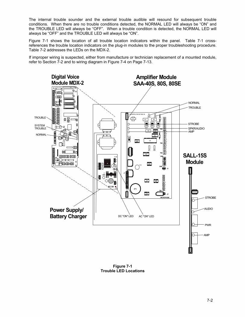
7-2
The internal trouble sounder and the external trouble audible will resound for subsequent trouble conditions. When there are no trouble conditions detected, the NORMAL LED will always be �ON� and the TROUBLE LED will always be �OFF�. When a trouble condition is detected, the NORMAL LED will always be �OFF� and the TROUBLE LED will always be �ON�.
Figure 7-1 shows the location of all trouble location indicators within the panel. Table 7-1 cross-references the trouble location indicators on the plug-in modules to the proper troubleshooting procedure. Table 7-2 addresses the LEDs on the MDX-2.
If improper wiring is suspected, either from manufacture or technician replacement of a mounted module, refer to Section 7-2 and to wiring diagram in Figure 7-4 on Page 7-13.
106
10 6
Digital VoiceModule MDX-2
S15
S14
S12
CH1 VOL
P83412 REV ( )
EARTHGND
REV:SN:
TB2
R46
RV1
C33
D13
D12
R59R60
R57R58
R55R56
R53R54
R51R52
R49R50
R47R48
R62
U17
U13
C48
C41
C40
C39
C38
C36
C35
C34
TB3
RV8
R72
RV9
RV10
R69
R68Q1
R73
Q2
RV5
R64 R63D11RV7
RV6
RV3
RV4
RV2
J5
J6
R65
U14
C43
C44
R71
U16C50
C49C47
U15
R66
R67
R70
C46
C45
U11
C42
C32
U12
D10
R41
R40
C30
C31
C29C28
R43
R44 R42
U10
R61
C37
R39
R38
C9
E1
F1
K1
R45
D3
J3
TB1
J2
C10 D2 D1
C8 R9 R2R5R7 R1C4 C2C7 C5
R32
K2
J1
D4
U8
C23
U7C27
C24C25
R34R35
D9
L2
U9
C26
L1
C21
D8R33
C22
J4
R36R37
D5
D7
D6
R28
R23
R10
R19 R13
R21R22 R14R17C17 C14 C12
U5
U6
C20
C19R26 R25 R30
R31 R29
R24C18
R16U3U4
C16R20 R18 C15
R8U1 R6C6
U2C11R15 C13 R11R12
R3R4 C3 C1
R27
+
+
+
+
+
S8
12
34
ON
12
34
ON
J1
MICROPHONE
TB5
E1SW5
SW4
TB3
TB2
TB1SW1 SW2 SW3
K1 K2
K3
F1
F2
X1 X2
J2
P1
C16
D1 D2
U1
U2
U3 U4
U5
U6
U8 U9
U10
+-
+-
+-
+-
+-+-
T1
+-
+-
+-
SAFEPATH P83167 REV B
AMBER GREEN
DCBA
T+
-SW
1
AC
ACAC
+-
DC
SW2
BAT
FAIL
NO
NC
C A
C F
AIL
C N
C N
O
SMP7PM
Power Supply/Battery Charger
Amplifier ModuleSAA-40S, 80S, 80SE
NORMALTROUBLE
STROBESPKR/AUDIOAMP
NORMAL
SYSTEM TROUBLE
TROUBLE
DC "ON" LED AC "ON" LED
SALL-15S Module
STROBE
AUDIO
AMP
PWR
Figure 7-1
Trouble LED Locations
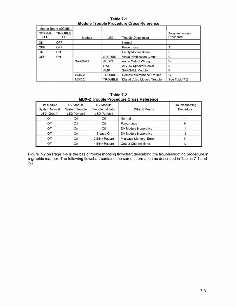
7-3
Table 7-1 Module Trouble Procedure Cross Reference
Mother Board (SCMB) NORMAL
LED TROUBLE
LED
Module
LED Trouble Description
Troubleshooting Procedure
ON OFF Normal OFF OFF Power Loss A ON ON Faulty Mother Board B OFF ON STROBE Visual Notification Circuit C SAA/SALL AUDIO Audio Output Wiring D PWR 24VDC Speaker Power E AMP SAA/SALL Module F RMS-2 TROUBLE Remote Microphone Trouble G MDX-2 TROUBLE Digital Voice Module Trouble See Table 7-2
Table 7-2 MDX-2 Trouble Procedure Cross Reference
DV Module System Normal
LED (Green)
DV Module System Trouble
LED (Amber)
DV Module Trouble Indicator
LED (Amber)
What it Means
Troubleshooting Procedure
On Off Off Normal ---- Off Off Off Power Loss H Off On Off DV Module Inoperative I Off On Steady-On DV Module Inoperative J Off On 2 Blink Pattern Message Memory Error K Off On 4 Blink Pattern Output Channel Error L
Figure 7-2 on Page 7-4 is the basic troubleshooting flowchart describing the troubleshooting procedure in a graphic manner. The following flowchart contains the same information as described in Tables 7-1 and 7-2.
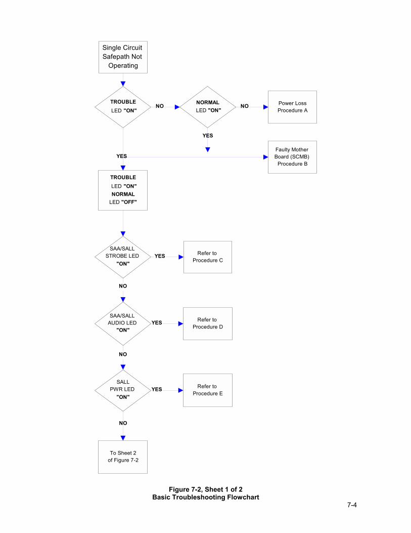
7-4
Single Circuit Safepath Not
Operating
TROUBLE LED "ON"
NORMAL LED "ON"
Power LossProcedure A
Faulty Mother Board (SCMB)
Procedure B
SALLPWR LED
"ON"
TROUBLE LED "ON"NORMAL
LED "OFF"
SAA/SALL STROBE LED
"ON"
Refer to Procedure C
SAA/SALL AUDIO LED
"ON"
Refer to Procedure D
Refer to Procedure E
To Sheet 2of Figure 7-2
NO NO
YES
YES
NO
YES
YES
YES
NO
NO
Figure 7-2, Sheet 1 of 2
Basic Troubleshooting Flowchart
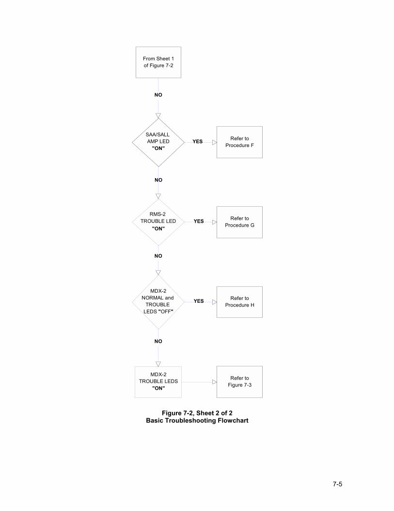
7-5
SAA/SALL AMP LED
"ON"
RMS-2 TROUBLE LED
"ON"
MDX-2NORMAL and
TROUBLE LEDS "OFF"
MDX-2TROUBLE LEDS
"ON"
From Sheet 1of Figure 7-2
Refer toProcedure F
Refer toProcedure H
Refer toProcedure G
Refer toFigure 7-3
NO
YES
YES
NO
NO
NO
YES
Figure 7-2, Sheet 2 of 2
Basic Troubleshooting Flowchart
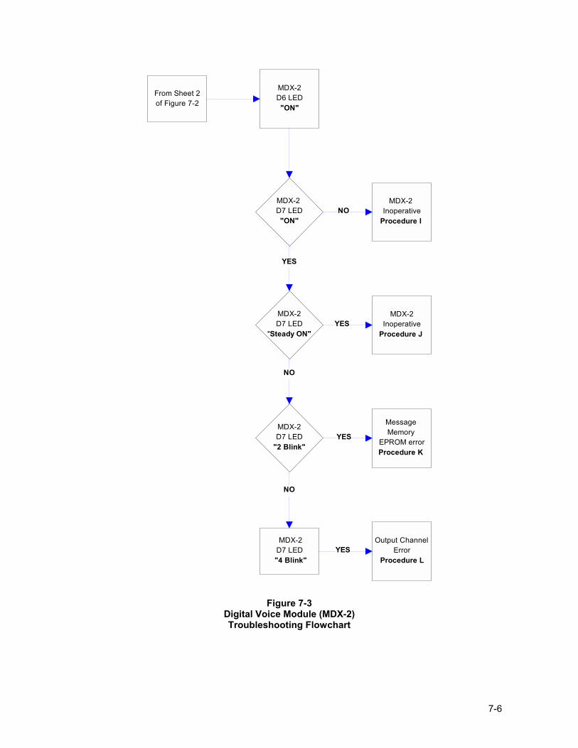
7-6
MDX-2D6 LED"ON"
Output Channel Error
Procedure L
MDX-2D7 LED
"2 Blink"
Message Memory
EPROM errorProcedure K
MDX-2 D7 LED"ON"
MDX-2 Inoperative
Procedure I
MDX-2D7 LED
"Steady ON"
MDX-2Inoperative
Procedure J
MDX-2D7 LED
"4 Blink"L
From Sheet 2of Figure 7-2
NO
YES
YES
NO
NO
YES
YES
Figure 7-3
Digital Voice Module (MDX-2) Troubleshooting Flowchart
7-7
WARNING: BEFORE PERFORMING ANY OF THE FOLLOWING TROUBLESHOOTING PROCEDURES, THE PRELIMINARY TROUBLESHOOTING INFORMATION AT THE BEGINNING OF THIS �TROUBLESHOOTING� SECTION ON PAGE 7-1, MUST BE READ, UNDERSTOOD, AND FOLLOWED.
Procedure A If the green NORMAL LED is �OFF�, the yellow TROUBLE LED is �OFF�, and no module LEDs are �ON�, then a power loss condition has occurred. A power loss condition may be caused by: 1. Loss of AC input voltage and/or battery back-up voltage. 2. Faulty internal wiring between the Power Supply module and the Motherboard (SCMB). 3. Faulty Power Supply module. 4. Faulty Motherboard (SCMB). Perform the following: 1. Check for 24 +/- 5VDC at TB6 on the SCMB. If voltage is not present, perform steps 2 and 3. 2. Remove Power Supply Cover. (See Figure 3-16 on Page 3-14) Observe if AC LED and DC LED are
�ON� (See Figure 9-5 on Page 9-10 for locations). a) If both LEDs are �ON�, inspect wiring and connections between the Power Supply and
TB6 on SCMB. b) If both LEDs are �OFF�, check 120VAC input to Power Supply. If AC is not present, check AC
source. If AC is present, replace Power Supply module. c) If AC LED is �ON� and DC LED is �OFF�, remove AC Power and Battery Power from the
Power Supply, disconnect 24VDC wires from TB6 on SCMB and allow panel to cool for 20 minutes. Re-apply AC power. If DC LED remains �OFF�, replace Power Supply module. If DC LED is �ON�, problem is a high current draw on the SCMB.
3. Replace the Mother Board (SCMB). NOTE: Mark all wires before removing components. When the trouble is repaired, and before
testing, replace all wires to the proper locations and replace all covers. Figure 7-4 on Page 7-13 is the internal module wiring diagram for wire connection locations.
Procedure B On the Single Circuit Mother Board (SCMB), if the green NORMAL LED is �ON� and the yellow TROUBLE LED is �ON�, then a faulty Mother Board condition has occurred. A faulty Mother Board condition may be caused by: 1. SCMB module inoperable. 2. Panel Microphone not properly plugged in. Perform the following: 1. Replace the SCMB module. 2. Check Panel Microphone for proper plug in. Procedure C On the Single Circuit Mother Board (SCMB), the green NORMAL LED is �OFF�, the yellow TROUBLE LED is �ON�, and on the SAA/SALL module the STR/STROBE LED is �ON�, then a visual notification output wiring trouble condition has occurred. A visual notification output wiring trouble condition might be caused by: 1. Missing EOLR on the visual notification output. 2. The Visual Notification Output field wiring is open or shorted. 3. A fuse on the SAA/SALL module is blown. 4. A faulty SAA/SALL module. 5. A faulty Motherboard (SCMB) module.
7-8
Perform the following: 1. Check EOLR and verify that it is a UL LISTED, 10K Ohm, 5% Tolerance, 1W Resistor. 2. Check that the EOLR is properly in place. 3. Verify that the Visual Notification Output field wiring is intact. 4. Verify that all fuses on the SAA/SALL module are functioning. 5. If trouble does not clear, remove strobe appliance circuit wiring from Motherboard and place a 10K
Ohm 1/4W minimum resistor on strobe output (Figure 3-1 on Page 3-2). If STR/STROBE LED turns �OFF�, the trouble is in the Strobe NAC Circuit. If trouble does not clear, replace the SAA/SALL module.
6. Replace the Motherboard (SCMB). Procedure D On the Single Circuit Mother Board (SCMB), the green NORMAL LED is �OFF�, the yellow TROUBLE LED is �ON�, and on the SAA/SALL module, the SPK/AUDIO LED is �ON�, then an audio output wiring trouble condition has occurred. An audio output wiring trouble condition might be caused by: 1. Missing end-of-line resistor on the audio output. 2. The audio output field wiring is open or shorted. 3. A faulty SAA/SALL module. 4. A faulty Motherboard (SCMB). Perform the following: 1. Check EOLR and verify that it is a UL LISTED 10K Ohm, 5% Tolerance, 1W Resistor. 2. Verify that the EOLR is properly in place. 3. Verify that the audio output field wiring is intact. 4. If trouble does not clear, remove audio appliance circuit wiring from Motherboard and place a 10K
Ohm 1/4W minimum resistor on audio output (Figure 3-1 on Page 3-2). If SPK/AUDIO LED turns �OFF�, the trouble is in the Audio NAC Circuit. If trouble does not clear, replace the SAA/SALL module.
5. Replace the Motherboard (SCMB). Procedure E On the Single Circuit Mother Board (SCMB), the green NORMAL LED is �OFF�, the yellow TROUBLE LED is �ON�, and on the SALL-15S module the PWR LED is �ON�, then an amplified speaker power output wiring trouble condition has occurred. An amplified speaker power output wiring trouble condition might be caused by: 1. Missing EOLR on the amplified speaker power output. 2. The Amplified Speaker Power Output field wiring is open or shorted. 3. A fuse on the SALL-15S module is blown. 4. A faulty SALL-15S module. 5. A faulty Motherboard (SCMB). Perform the following: 1. Check EOLR and verify that it is a UL LISTED 10K Ohm, 5% Tolerance, 1W Resistor. 2. Verify that the end-of-line resistor is properly in place. 3. Verify that the Amplified Speaker Power Output field wiring is intact. 4. Verify that all fuses on the SALL-15S module are intact. (See Figure 9-8 on Page 9-15 for locations) 5. If trouble does not clear, remove SPKR AMP appliance circuit wiring from Motherboard and place a
10K Ohm 1/4W minimum resistor on the output (Figure 3-1 on Page 3-2). If PWR LED turns �OFF�, the trouble is in the Speaker Power NAC Circuit. If trouble does not clear, replace the SALL-15S module.
6. Replace the Motherboard (SCMB).
7-9
Procedure F On the Single Circuit Mother Board (SCMB), the green NORMAL LED is �OFF�, the yellow TROUBLE LED is �ON�, and the AMP LED on the SAA/SALL module is �ON�, then an amplifier trouble condition has occurred. An amplifier trouble condition may be caused by: 1. A faulty SAA/SALL module. 2. A faulty Motherboard (SCMB). Perform the following: 1. Replace the SAA/SALL module. 2. Replace the Motherboard (SCMB). Procedure G On the Single Circuit Mother Board (SCMB), the green NORMAL LED is �OFF�, the yellow TROUBLE LED is �ON�, and on the Remote Microphone Station (RMS-2) TROUBLE LED is �ON�, then a faulty Remote Microphone Station condition has occurred. A faulty Remote Microphone Station condition may be caused by: 1. Improperly configured panel. 2. Faulty wiring between the panel and the remote microphone station. 3. Faulty REM MIC fuse (F1) on the SCMB module. 4. Faulty Remote Microphone Station. Perform the following: 1. If the system does not have a remote microphone attached then switch the Remote Microphone DIP
switch (RM) OFF. (See Figure 3-18 on Page 3-17 for switch location) 2. Verify field wiring between the panel and the remote microphone station. (See Appendix B) 3. Replace F1 on the SCMB module. (See Figure 9-3 on Page 9-7 for fuse location) 4. Replace the Remote Microphone Station. Procedure H On the Single Circuit Mother Board (SCMB), the green NORMAL LED is �OFF�, the yellow TROUBLE LED is �ON�, and the Digital Voice Module NORMAL LED, SYSTEM TROUBLE LED, and TROUBLE LED are �OFF�, then the Digital Voice Module (MDX-2) may be completely inoperative due to power loss. This condition is caused by: 1. Input voltage is not within proper range or polarity is incorrect. 2. Blown fuse (F2) on the MDX-2. 3. One or more LED's are broken. 4. Faulty Motherboard (SCMB) Perform the following: 1. Verify the Voltage at TB6 on the Motherboard (DCMB) is within proper range and that polarity is
correct. a. Check appropriate fuse on MDX-2. b. Replace Motherboard.
If, after the above procedure is completed, the trouble condition persists, the trouble condition is caused by broken LED's on the MDX-2 Module. The LED's on the MDX-2 module are not field replaceable. Digital voice modules with broken LED's shall be replaced immediately, following the �SAFEPATH® Module Replacement Procedure�, set forth at the end of this section.
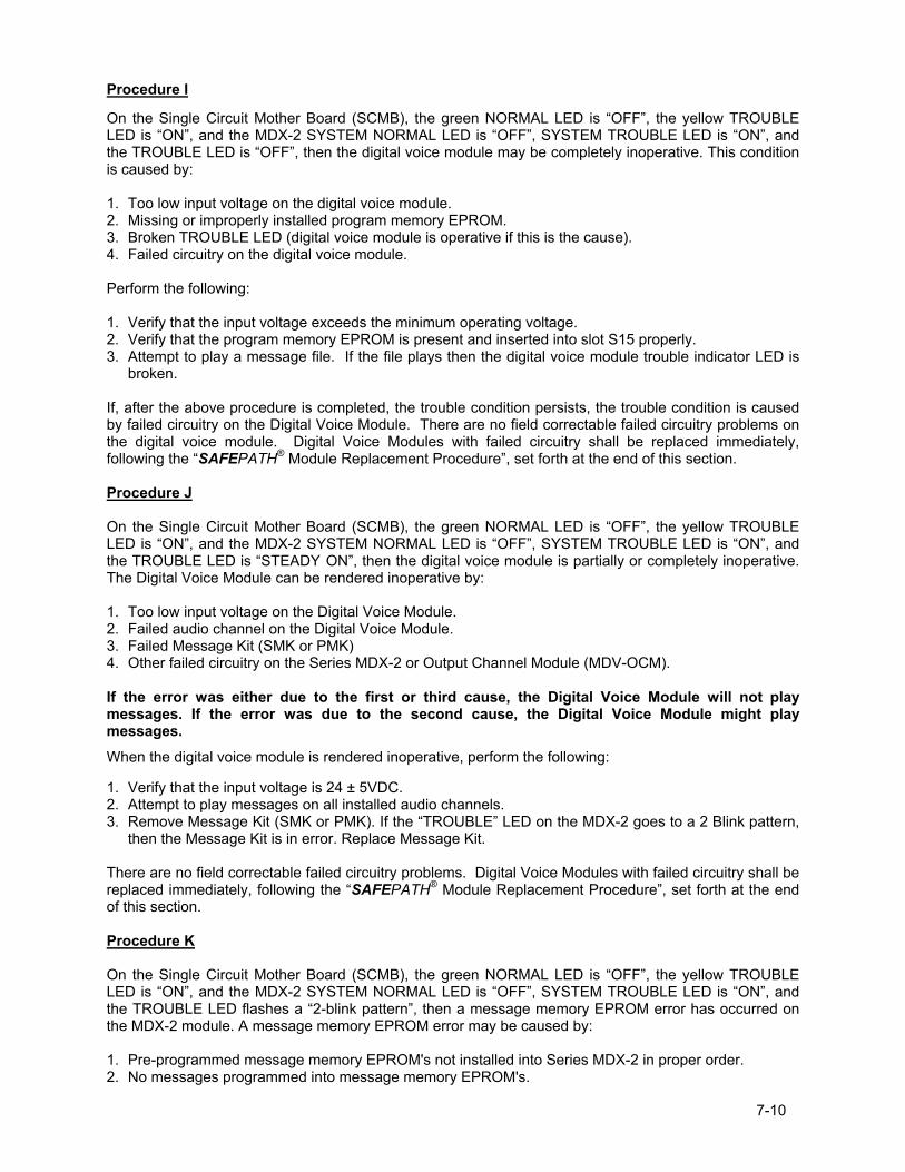
7-10
Procedure I
On the Single Circuit Mother Board (SCMB), the green NORMAL LED is �OFF�, the yellow TROUBLE LED is �ON�, and the MDX-2 SYSTEM NORMAL LED is �OFF�, SYSTEM TROUBLE LED is �ON�, and the TROUBLE LED is �OFF�, then the digital voice module may be completely inoperative. This condition is caused by: 1. Too low input voltage on the digital voice module. 2. Missing or improperly installed program memory EPROM. 3. Broken TROUBLE LED (digital voice module is operative if this is the cause). 4. Failed circuitry on the digital voice module. Perform the following: 1. Verify that the input voltage exceeds the minimum operating voltage. 2. Verify that the program memory EPROM is present and inserted into slot S15 properly. 3. Attempt to play a message file. If the file plays then the digital voice module trouble indicator LED is
broken. If, after the above procedure is completed, the trouble condition persists, the trouble condition is caused by failed circuitry on the Digital Voice Module. There are no field correctable failed circuitry problems on the digital voice module. Digital Voice Modules with failed circuitry shall be replaced immediately, following the �SAFEPATH® Module Replacement Procedure�, set forth at the end of this section. Procedure J On the Single Circuit Mother Board (SCMB), the green NORMAL LED is �OFF�, the yellow TROUBLE LED is �ON�, and the MDX-2 SYSTEM NORMAL LED is �OFF�, SYSTEM TROUBLE LED is �ON�, and the TROUBLE LED is �STEADY ON�, then the digital voice module is partially or completely inoperative. The Digital Voice Module can be rendered inoperative by: 1. Too low input voltage on the Digital Voice Module. 2. Failed audio channel on the Digital Voice Module. 3. Failed Message Kit (SMK or PMK) 4. Other failed circuitry on the Series MDX-2 or Output Channel Module (MDV-OCM). If the error was either due to the first or third cause, the Digital Voice Module will not play messages. If the error was due to the second cause, the Digital Voice Module might play messages. When the digital voice module is rendered inoperative, perform the following: 1. Verify that the input voltage is 24 ± 5VDC. 2. Attempt to play messages on all installed audio channels. 3. Remove Message Kit (SMK or PMK). If the �TROUBLE� LED on the MDX-2 goes to a 2 Blink pattern,
then the Message Kit is in error. Replace Message Kit. There are no field correctable failed circuitry problems. Digital Voice Modules with failed circuitry shall be replaced immediately, following the �SAFEPATH® Module Replacement Procedure�, set forth at the end of this section. Procedure K On the Single Circuit Mother Board (SCMB), the green NORMAL LED is �OFF�, the yellow TROUBLE LED is �ON�, and the MDX-2 SYSTEM NORMAL LED is �OFF�, SYSTEM TROUBLE LED is �ON�, and the TROUBLE LED flashes a �2-blink pattern�, then a message memory EPROM error has occurred on the MDX-2 module. A message memory EPROM error may be caused by: 1. Pre-programmed message memory EPROM's not installed into Series MDX-2 in proper order. 2. No messages programmed into message memory EPROM's.
7-11
3. Missing or improperly installed message memory EPROM's. 4. One or more of the messages were not programmed completely. 5. Failed circuitry on the MDX-2. If the error was due to one of the first four causes, the trouble will clear automatically when the cause is corrected. The first four causes should only occur when power is first turned on to the Series MDX-2. When a message memory error is indicated, perform the following: 1. Verify that the preprogrammed message memory EPROM's were installed in the correct sockets on
the Series MDX-2. See Figure 9-3 on Page 9-7 for proper chip location. An EPROM must always be installed in socket S14. If between one and two minutes of message memory is required, the first EPROM must be installed into socket S14 and the second EPROM into socket S12.
2. Verify, at least one message is programmed into the message memory EPROM's. 3. Verify that all message memory EPROM's are inserted into their sockets properly. 4. Verify that there are no partially programmed messages on the message memory EPROM's. This can
only be done using commands on the serial port, which is located on the optional Ground Fault Detection/Computer Interface Module.
If, after the above procedure is completed, the trouble condition persists, the trouble condition is caused by failed circuitry on the Series MDX-2. There are no field correctable failed circuitry problems on the Series MDX-2. Series MDX-2's with failed circuitry shall be replaced immediately, following the Replacement Procedure, set forth at the end of this section. Procedure L On the Single Circuit Mother Board (SCMB), the green NORMAL LED is �OFF�, the yellow TROUBLE LED is �ON�, and the MDX-2 SYSTEM NORMAL LED is �OFF�, SYSTEM TROUBLE LED is �ON�, and the TROUBLE LED flashes a �4-blink pattern�, then an audio channel error has occurred. An audio channel error may be caused by: 1. Too low an audio level while playing a message. 2. Pause in message while playing a message that lasts longer than 3 seconds. If the error occurs while playing a file, then the error was due to the first cause. If the error occurs immediately after turning on power to the Series MDX-2, the error was due to the second cause. If the error was due to either cause while playing a message, the trouble will clear automatically when audio is again detected while a message is playing. If the error is due to the third cause, the trouble will clear automatically when the output is no longer loaded down while a message is playing. If the error was due to the fourth cause, the trouble will clear automatically when the module is properly installed and input power is cycled off and on. When an audio channel error is indicated, perform the following: 1. Have the message re-recorded, shortening duration of the pause. Section 7-2 - SAFEPATH® Module Replacement Procedure Return any modules that are malfunctioning, after all troubleshooting operations have been performed, for factory repair or replacement. If it is necessary to return a Single Circuit SAFEPATH® Module, replace the malfunctioning modules immediately in the following manner: 1. Disconnect battery backup power from the Single Circuit SAFEPATH® Panel. 2. Disconnect AC input power from the Single Circuit SAFEPATH® Panel. 3. Identify all wiring connections to make sure they will be reconnected identically on the replacement. 4. Disconnect all wiring connections.
7-12
5. Remove the malfunctioning module(s) and install the replacement module(s). Perform all checkout procedures described in the �Installation� section of this manual to make sure the replacement module(s) is (is) operating properly.
Section 7-3 � Single Circuit SAFEPATH® Module Wiring Diagram Figure 7-4 on Page 7-13 illustrates the Single Circuit SAFEPATH® Module Wiring between modules. Note the wires are color-coded. If major modules have been replaced or improper wiring is suspected, use this wiring diagram to trace the proper wiring routes.
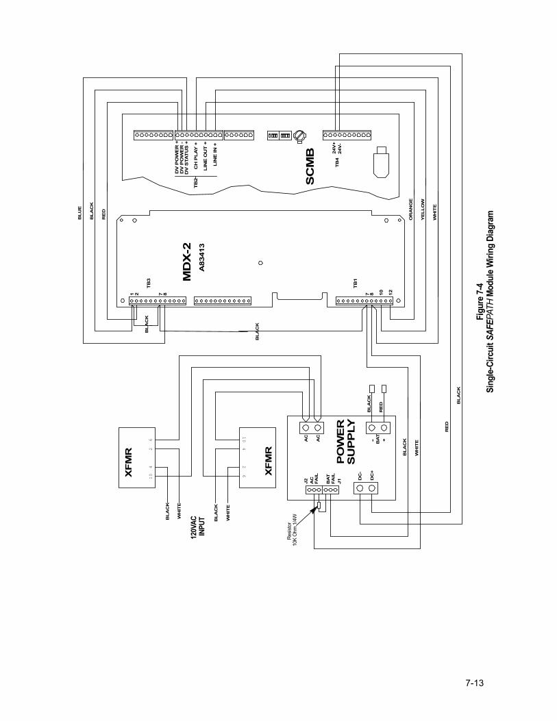
7-13
DC
+
DC
-
TB
4
AC
AC
26
410
24V
-24
V+
410
26
RE
D
BL
AC
K
WH
ITE
BL
AC
K
WH
ITE
BL
AC
K
AC
BA
TFA
IL
FAIL
- BA
T+
RE
D
BL
AC
K
TB
3
7 81 2 7 8
TB
1
1210
DV
PO
WE
R +
DV
STA
TU
S +
DV
PO
WE
R -
TB
2C
H P
LA
Y +
LIN
E O
UT
+
LIN
E IN
+
MD
X-2
A83
413
BL
UE
BL
AC
K
RE
D
WH
ITE
YE
LL
OW
OR
AN
GE
BL
AC
K
WH
ITE
BL
AC
K
BL
AC
K
J2 J1
SC
MB
XF
MR
PO
WE
RS
UP
PLY
XF
MR
120V
AC IN
PUT
R
esist
or10
K O
hm 1
/4W
Fig
ure 7
-4Si
ngle-
Circ
uit SAFE P
ATH
Modu
le W
iring
Diag
ram

7-14
Intentionally Blank
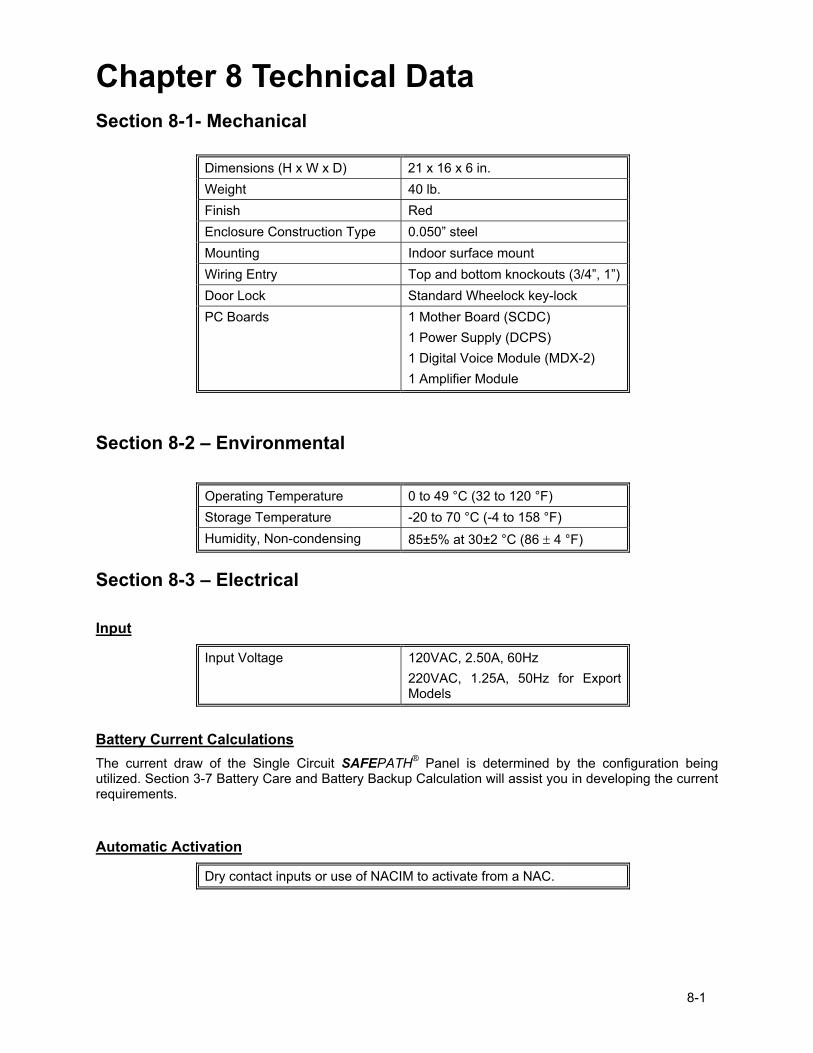
8-1
Chapter 8 Technical Data Section 8-1- Mechanical
Dimensions (H x W x D) 21 x 16 x 6 in. Weight 40 lb. Finish Red Enclosure Construction Type 0.050� steel Mounting Indoor surface mount Wiring Entry Top and bottom knockouts (3/4�, 1�) Door Lock Standard Wheelock key-lock PC Boards 1 Mother Board (SCDC)
1 Power Supply (DCPS) 1 Digital Voice Module (MDX-2) 1 Amplifier Module
Section 8-2 � Environmental
Operating Temperature 0 to 49 °C (32 to 120 °F) Storage Temperature -20 to 70 °C (-4 to 158 °F) Humidity, Non-condensing 85±5% at 30±2 °C (86 ± 4 °F)
Section 8-3 � Electrical Input
Input Voltage 120VAC, 2.50A, 60Hz 220VAC, 1.25A, 50Hz for Export Models
Battery Current Calculations The current draw of the Single Circuit SAFEPATH® Panel is determined by the configuration being utilized. Section 3-7 Battery Care and Battery Backup Calculation will assist you in developing the current requirements.
Automatic Activation
Dry contact inputs or use of NACIM to activate from a NAC.
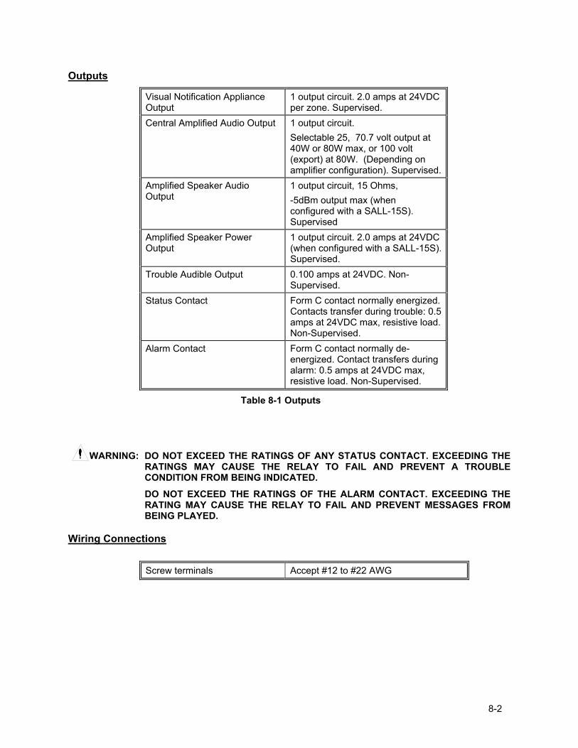
8-2
Outputs
Visual Notification Appliance Output
1 output circuit. 2.0 amps at 24VDC per zone. Supervised.
Central Amplified Audio Output 1 output circuit. Selectable 25, 70.7 volt output at 40W or 80W max, or 100 volt (export) at 80W. (Depending on amplifier configuration). Supervised.
Amplified Speaker Audio Output
1 output circuit, 15 Ohms, -5dBm output max (when configured with a SALL-15S). Supervised
Amplified Speaker Power Output
1 output circuit. 2.0 amps at 24VDC (when configured with a SALL-15S). Supervised.
Trouble Audible Output 0.100 amps at 24VDC. Non-Supervised.
Status Contact Form C contact normally energized. Contacts transfer during trouble: 0.5 amps at 24VDC max, resistive load. Non-Supervised.
Alarm Contact Form C contact normally de-energized. Contact transfers during alarm: 0.5 amps at 24VDC max, resistive load. Non-Supervised.
Table 8-1 Outputs
WARNING: DO NOT EXCEED THE RATINGS OF ANY STATUS CONTACT. EXCEEDING THE RATINGS MAY CAUSE THE RELAY TO FAIL AND PREVENT A TROUBLE CONDITION FROM BEING INDICATED. DO NOT EXCEED THE RATINGS OF THE ALARM CONTACT. EXCEEDING THE RATING MAY CAUSE THE RELAY TO FAIL AND PREVENT MESSAGES FROM BEING PLAYED.
Wiring Connections
Screw terminals Accept #12 to #22 AWG
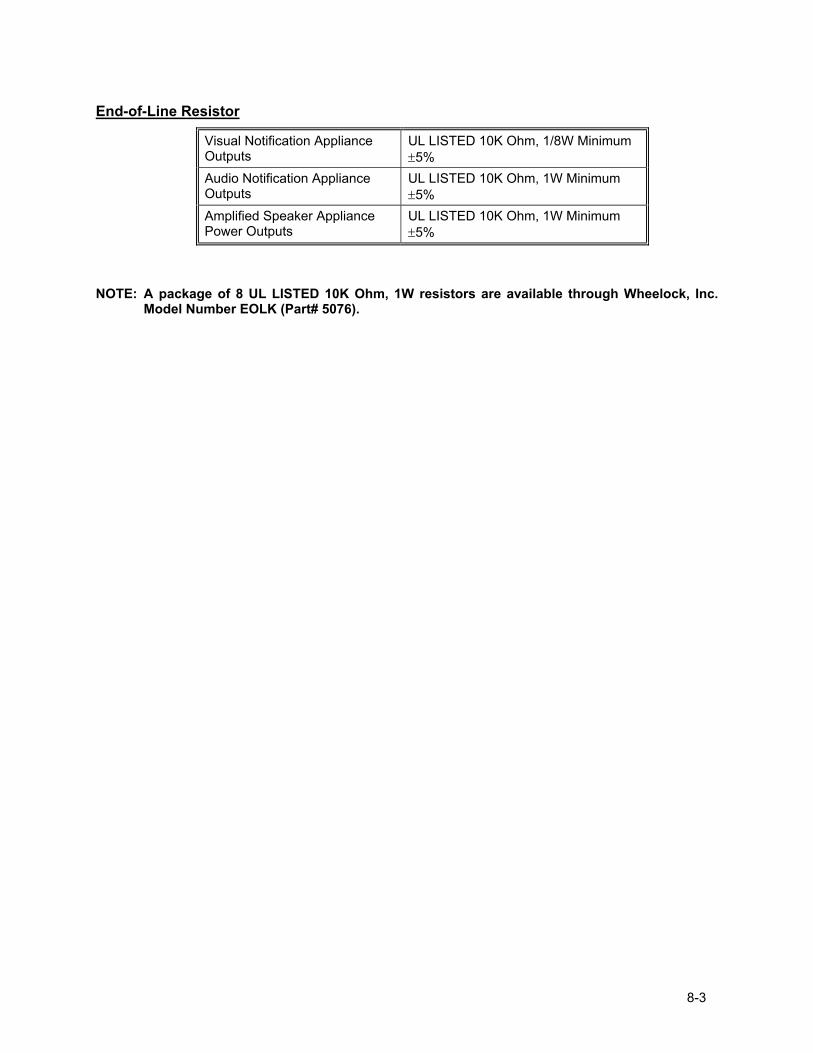
8-3
End-of-Line Resistor
NOTE: A package of 8 UL LISTED 10K Ohm, 1W resistors are available through Wheelock, Inc. Model Number EOLK (Part# 5076).
Visual Notification Appliance Outputs
UL LISTED 10K Ohm, 1/8W Minimum ±5%
Audio Notification Appliance Outputs
UL LISTED 10K Ohm, 1W Minimum ±5%
Amplified Speaker Appliance Power Outputs
UL LISTED 10K Ohm, 1W Minimum ±5%

8-4
Intentionally Blank
9-1
Chapter 9 - Module Descriptions Section 9-1 - Introduction There are ten modules in the Single Circuit SAFEPATH® Panel product line. The ten modules are: 1. Single Circuit Mother Board (SCMB) 2. Digital Voice Module (MDX-2) 3. Power Supply / Battery Charger (DCPS) 4. Supervised Audio System Amplifier/Signal Circuit Module (SAA-40S) 5. Supervised Audio System Amplifier/Signal Circuit Module (SAA-80S/SE*) 6. Supervised Audio Line Level Module (SALL-15S) 7. Speaker Circuit Splitter (4 way) (SC-SPL) 8. Notification Appliance Circuit Interface Module (NACIM) 9. Remote Microphone Station (RMS-2) 10. Auxiliary Input Module (AIM-3) * 100 Volt for European Installations
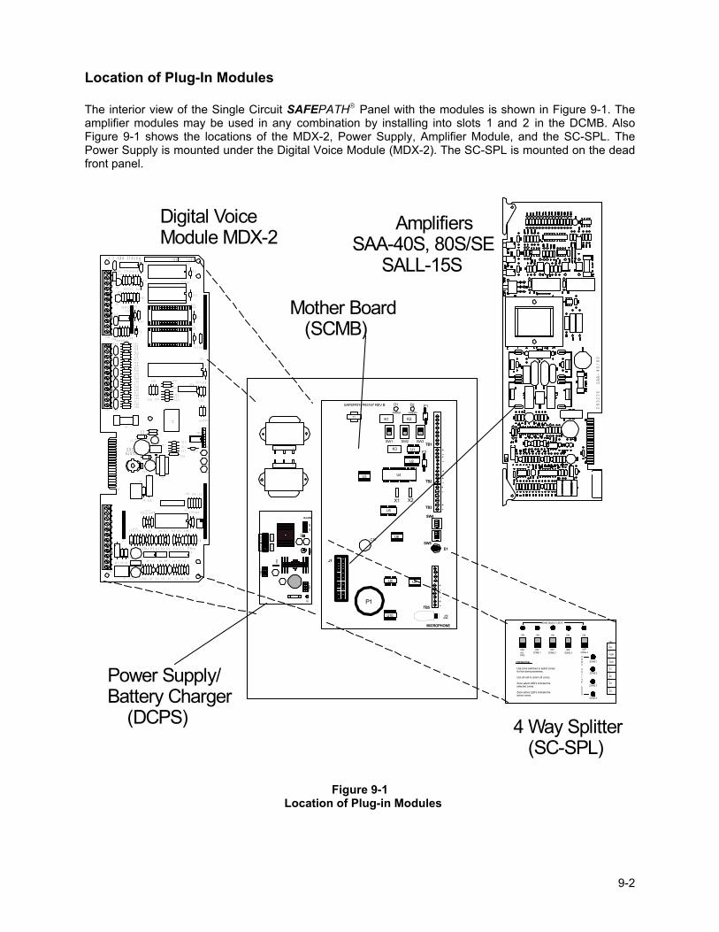
9-2
Location of Plug-In Modules The interior view of the Single Circuit SAFEPATH Panel with the modules is shown in Figure 9-1. The amplifier modules may be used in any combination by installing into slots 1 and 2 in the DCMB. Also Figure 9-1 shows the locations of the MDX-2, Power Supply, Amplifier Module, and the SC-SPL. The Power Supply is mounted under the Digital Voice Module (MDX-2). The SC-SPL is mounted on the dead front panel.
106
10 6
4 Way Splitter (SC-SPL)
AmplifiersSAA-40S, 80S/SE SALL-15S
Digital VoiceModule MDX-2
P83236 SAA-40/80
S15
S14
S12
CH1 VOL
P83412 REV ( )
EARTHGND
REV:SN:
TB2
R46
RV1
C33
D13
D12
R59R60
R57R58
R55R56
R53R54
R51R52
R49R50
R47R48
R62
U17
U13
C48
C41
C40
C39
C38
C36
C35
C34
TB3
RV8
R72
RV9
RV10
R69
R68Q1
R73
Q2
RV5
R64 R63D11RV7
RV6
RV3
RV4
RV2
J5
J6
R65
U14
C43
C44
R71
U16C50
C49C47
U15
R66
R67
R70
C46
C45
U11
C42
C32
U12
D10
R41
R40
C30
C31
C29C28
R43
R44 R42
U10
R61
C37
R39
R38
C9
E1
F1
K1
R45
D3
J3
TB1
J2
C10 D2 D1
C8 R9 R2R5R7 R1C4 C2C7 C5
R32
K2
J1
D4
U8
C23
U7C27
C24C25
R34R35
D9
L2
U9
C26
L1
C21
D8R33
C22
J4
R36R37
D5
D7
D6
R28
R23
R10
R19 R13
R21R22 R14R17C17 C14 C12
U5
U6
C20
C19R26 R25 R30
R31 R29
R24C18
R16U3U4
C16R20 R18 C15
R8U1 R6C6
U2C11R15 C13 R11R12
R3R4 C3 C1
R27
+
+
+
+
+
S8
12
34
ON
12
34
ON
J1
MICROPHONE
TB5
E1SW5
SW4
TB3
TB2
TB1SW1 SW2 SW3
K1 K2
K3
F1
F2
X1 X2
J2
P1
C16
D1 D2
U1
U2
U3 U4
U5
U6
U8 U9
U10
+-
+-+-
+-
+-+-
T1
+-
+-
+-
SAFEPATH P83167 REV B
AMBER GREEN
DCBA
T+
-SW
1
AC
ACAC
+-
DC
SW2
BAT
FAIL
NO N
C C
AC
FAIL
C NC
NO
SMP7PM
Power Supply/Battery Charger (DCPS)
ZONE SELECT LED'S
ON
OFF
ON ON
OFF OFF
ON
OFF
ON
OFF ALL CALL
ZONE 1 ZONE 2 ZONE 3 ZONE 4
ZONE 1
ZONE 2
ZONE 3
ZONE 4
ZONE
ACTIVE
LEDS
Z4
Z3
Z2
Z1
AUD
PWR
ALL
TB1
+
_+_
+_+_
+_
+
_
+_
OPERATION:
Use zone switches to select zonesfor live announcements.
Use all-call to select all zones.
Zone select LED's indicate theselected zones.
Zone active LED's indicate theactive zones.
Mother Board (SCMB)
Figure 9-1
Location of Plug-in Modules
9-3
Section 9-2 - Single Circuit Mother Board (SCMB) Wheelock, Inc. Part Number 108974 The Single Circuit Mother Board provides all signal handling capabilities between itself and the amplifier modules, terminal blocks for output wiring, and connectors for handling signals from the digital voice module. The Single Circuit Mother Board is illustrated in Figure 9-2 on Page 9-5. A single amplifier module is connected to the SCMB. A single channel from the Digital Voice Module (MDX-2) is connected to the SCMB. The digital voice module is mounted on the power supply cover and wired to the Mother Board. The digital voice module channel will play through the amplifier module installed. The microphone input is located in the lower right corner of the board and is used for live voice announcements. Form C contacts are available for remote monitoring of Alarm Status and Trouble Status. Also remote trouble power is available at 24VDC, 0.100 Amps, that is non-supervised. Single Circuit Mother Board supervises the Digital Voice Module (MDX-2), Power Supply, and the amplifier module (SAA-40S, SAA-80S/SE, or SALL-15S) for proper operation. The microphone is supervised for connection. The channel play contacts from the digital voice module (MDX-2) are monitored to determine their status (e.g. active or inactive). If the channel play contact is inactive, the control module routes a supervision tone to the amplifier circuit module and monitors the amplifier for functionality. If the channel playing contact is active, the control module routes the audio from that MDX-2 line output to the amplifier circuit module. Wiring used to monitor the channel play contacts and to route the line output from the Digital Voice Module is supervised for open and short circuit conditions. The Power Supply module is supervised for two conditions: low AC input power, and low battery voltage. The wiring between the controller module and the battery charger is supervised for open and short circuit conditions. The amplifier module is supervised for two failure conditions: field wiring trouble conditions and amplifier audio output trouble conditions. The SCMB only supervises the audio output during standby conditions. When either a message is playing from the Digital Voice Module or a live announcement is being made from the microphone, the field wiring and audio output are not supervised. The strobe NAC circuit can be used with standard non-synchronized strobes or the circuit can be place in the SYNC mode for synchronizing Wheelock, Inc. synchronized strobes. Synchronization is accomplished by turning �ON� DIP Switch SW5, Position 3 (SYNC) on the SAMB. The strobe NAC circuit on the amplifier module is also supervised in the standby mode for field wiring trouble conditions. If at any time a trouble condition is detected, the SCMB will energize the internal audible, the external trouble audible circuit, and transfer the Form C trouble contact to the trouble position, turn �OFF� the NORMAL LED, and turn �ON� the TROUBLE LED. There are two fuses on the Mother Board. F1 is the fuse for the external trouble audible circuit, and F2 is the fuse for the Remote Microphone Station power. Both fuses are rated at 0.5A. See Figure 9-2 on Page 9-5 for fuse location.
Fuse Rating
F1 0.5A F2 0.5A
9-4
Nominal Specifications: Input Voltage Range 20 to 28VDC Supply Current (Idle) at 24VDC 75mA Supply Current (Full Load) at 24VDC 150mA Operating Temperature Range 0 to 49 Degrees C (32-120 Degrees F) Humidity Range 0 to 85%, Non-condensing
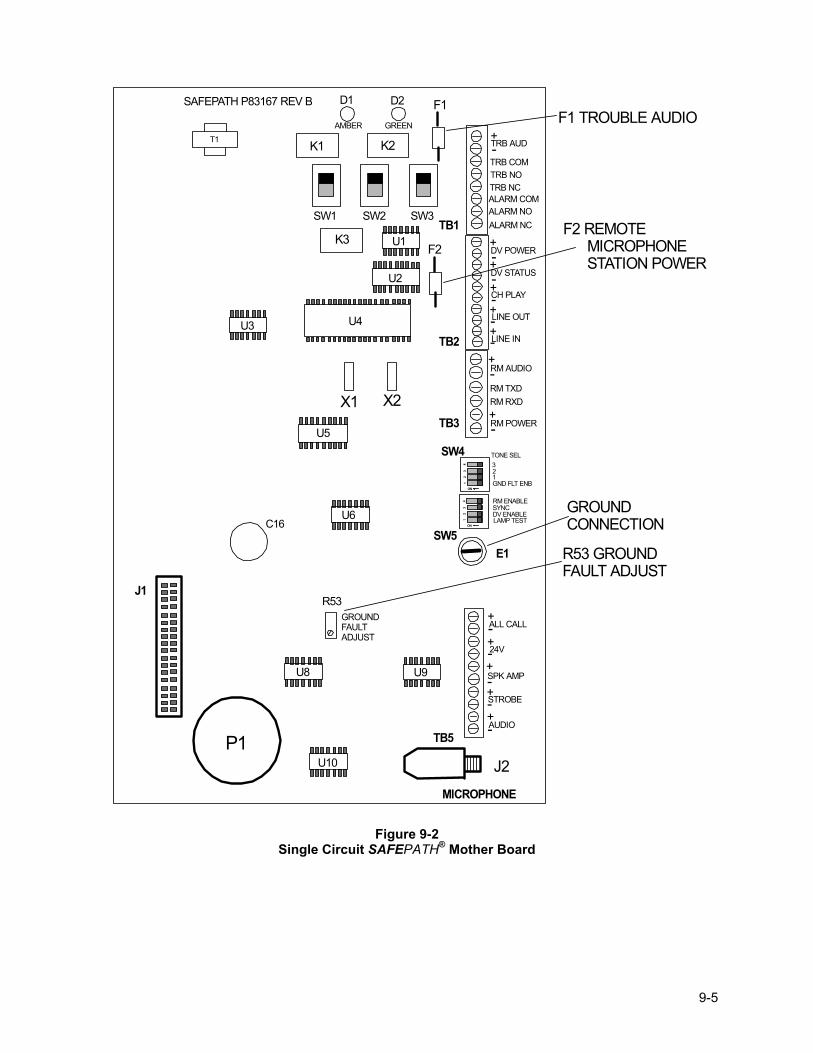
9-5
12
34
ON
12
34
ON
J1
MICROPHONE
TB5
E1SW5
SW4
TB3
TB2
TB1SW1 SW2 SW3
K1 K2
K3
F1
F2
X1 X2
J2P1
C16
D1 D2
U1
U2
U3 U4
U5
U6
U8 U9
U10
+-
+-+-
+-
+-+-
T1
+-
+-
+-
SAFEPATH P83167 REV B
AMBER GREEN
TRB AUD
TRB COMTRB NOTRB NCALARM COMALARM NOALARM NC
DV POWER
DV STATUS
CH PLAY
LINE OUT
LINE IN
RM AUDIO
RM TXDRM RXD
RM POWER
+
+-
-
TONE SEL321GND FLT ENB
RM ENABLESYNCDV ENABLELAMP TEST
AUDIO
STROBE
SPK AMP
24V
ALL CALL
+-
+-
GROUNDFAULTADJUST
R53
GROUND CONNECTION
R53 GROUND FAULT ADJUST
F1 TROUBLE AUDIO
F2 REMOTE MICROPHONE STATION POWER
Figure 9-2 Single Circuit SAFEPATH® Mother Board
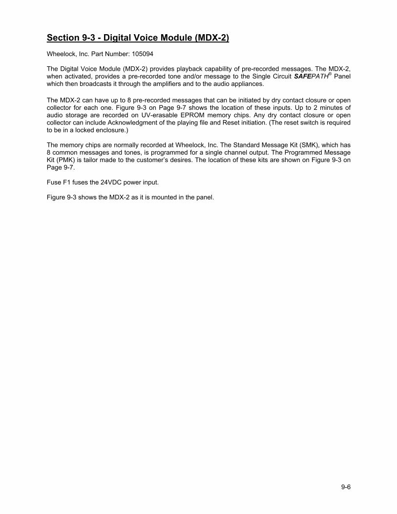
9-6
Section 9-3 - Digital Voice Module (MDX-2) Wheelock, Inc. Part Number: 105094 The Digital Voice Module (MDX-2) provides playback capability of pre-recorded messages. The MDX-2, when activated, provides a pre-recorded tone and/or message to the Single Circuit SAFEPATH® Panel which then broadcasts it through the amplifiers and to the audio appliances. The MDX-2 can have up to 8 pre-recorded messages that can be initiated by dry contact closure or open collector for each one. Figure 9-3 on Page 9-7 shows the location of these inputs. Up to 2 minutes of audio storage are recorded on UV-erasable EPROM memory chips. Any dry contact closure or open collector can include Acknowledgment of the playing file and Reset initiation. (The reset switch is required to be in a locked enclosure.) The memory chips are normally recorded at Wheelock, Inc. The Standard Message Kit (SMK), which has 8 common messages and tones, is programmed for a single channel output. The Programmed Message Kit (PMK) is tailor made to the customer�s desires. The location of these kits are shown on Figure 9-3 on Page 9-7. Fuse F1 fuses the 24VDC power input. Figure 9-3 shows the MDX-2 as it is mounted in the panel.
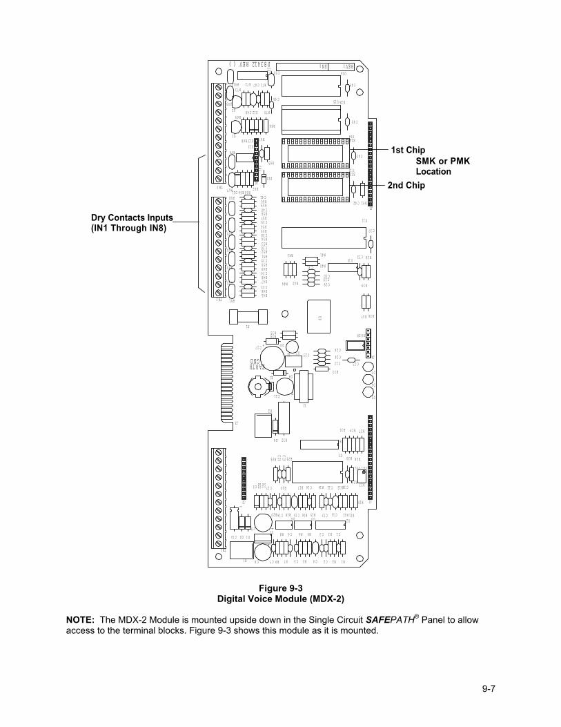
9-7
S15
S14
S12
CH1 VOL
P83412 REV ( )
EARTHGND
REV:SN:
TB2
R46
RV1
C33
D13
D12
R59R60
R57R58
R55R56
R53R54
R51R52
R49R50
R47R48
R62
U17
U13
C48
C41
C40
C39
C38
C36
C35
C34
TB3
RV8
R72
RV9
RV10
R69
R68Q1
R73
Q2
RV5
R64 R63D11RV7
RV6
RV3
RV4
RV2
J5
J6
R65
U14
C43
C44
R71
U16C50
C49C47
U15
R66
R67
R70
C46
C45
U11
C42
C32
U12
D10
R41
R40
C30
C31
C29C28
R43
R44 R42
U10
R61
C37
R39
R38
C9
E1
F1
K1
R45
D3
J3
TB1
J2
C10 D2 D1
C8 R9 R2R5R7 R1C4 C2C7 C5
R32
K2
J1
D4
U8
C23
U7C27
C24C25
R34R35
D9
L2
U9
C26
L1
C21
D8R33
C22
J4
R36R37
D5
D7
D6
R28
R23
R10
R19 R13
R21R22 R14R17C17 C14 C12
U5
U6C20C19R26 R25 R30
R31 R29
R24C18
R16U3U4
C16R20 R18 C15
R8U1 R6C6
U2C11R15 C13 R11R12
R3R4 C3 C1
R27
+
+
+
+
+
S8
Dry Contacts Inputs(IN1 Through IN8)
1st Chip
2nd Chip
SMK or PMKLocation
Figure 9-3
Digital Voice Module (MDX-2)
NOTE: The MDX-2 Module is mounted upside down in the Single Circuit SAFEPATH® Panel to allow access to the terminal blocks. Figure 9-3 shows this module as it is mounted.
9-8
Section 9-4 - Power Supply / Battery Charger (DCPS) Wheelock, Inc. Part Number: 107378 The Power Supply / Battery Charger (Figure 9-4) provides the Single Circuit SAFEPATH® Panel with a power supply/battery charger with an output of 24VDC with a maximum current of 6 Amps. The battery charger section is capable of charging a 40 AH battery in 48 hours. The Power Supply is protected with short circuit protection and thermal shutdown. It also contains Form C contacts for external monitoring of AC Failure and Battery Failure. �AC FAIL� is indicated with a minimum of (6) hour delay. LOW BATTERY is indicated on the �BAT FAIL� contacts when the battery voltage drops below 20VDC. NO BATTERY PRESENT is indicated on �BAT FAIL� terminals within 2 minutes. The AC LED indicates that AC is applied to the Power Supply. The DC LED indicates that the DCPS output is 24VDC.
D C
BAT
+-
SW1
AC
ACAC
+-
DC
SW2
BAT
FAIL
NO N
C C
AC
FAIL
C NC
NO
SMP7PM
GREEN LED - INDICATES AC VOLTAGE IS APPLIED TO THIS BOARD
28 VOLT AC INPUT FROM TRANSFORMER
24 VDC BACKUPBATTERY INPUT
RED LED - INDICATES POWER SUPPLY OUTPUT VOLTAGE IS AVAILABLE
BATTERY INPUT FUSE
24 VDC, 6 AMP OUTPUT TO MOTHER BOARD
BATTERY SUPERVISION
AC INPUT SUPERVISION
Figure 9-4 Power Supply / Battery Charger (DCPS)
9-9
Section 9-5 - Supervised Audio System Amplifier/Signal Circuit Module, 40 Watts (SAA-40S)
Wheelock, Inc. Part Number: 105493 The supervised audio system amplifier/signal circuit module, 40 watts (SAA) provides audio amplification for the SAFEPATH® system. The amplifier can be selected to have either a 25V or a 70.7V audio output. The amplifier contains a switch mode power supply, a linear amplifier, and supervision circuitry. The switching power supply is used to provide a constant DC voltage to the amplifier while the input voltage is allowed to fluctuate over its operating range. The amplifier amplifies the low-level 600-ohm audio to 40 watts output at either 25V or 70.7V. The supervision circuit monitors field speaker wiring integrity, field strobe wiring integrity, and amplifier functionality. The module can be field configured for either 25V or 70.7V output. The configuration is done using a two-position slide switch (S1) on the printed circuit board. One position (down) configures the amplifier to have a 25V output and the other position (up) configures the amplifier to have a 70.7V output. See Figure 9-5 on Page 9-10 for switch location. The amplifier supervises both the strobe field wiring and the speaker field wiring with a DC current. The strobe field wiring is supervised with a reverse polarity technique, which applies a DC voltage with one polarity to supervise the wiring and then reverses the polarity to energize the strobes. The speaker field wiring is supervised with a DC current, which is removed when audio is being played. Both field-wiring circuits are only supervised in the standby state. The amplifier is supervised by monitoring the amplifier output for audio. The state of each of the three supervision features is indicated via three LEDs on the module. See Figure 9-5 on Page 9-10 for LED locations. There are two fuses on the printed circuit board, F1 and F2. Fuse F1 is the main fuse for the entire board. F2 is the fuse for the strobe power. See Figure 9-5 on Page 9-10 for fuse locations. Two UL LISTED 10K Ohm, 1W, End of Line Resistors are included with this module.
Fuse Rating
F1 10A F2 3A
Nominal Specifications: Rated Output at 1kHz 40 Watts
Input Sensitivity 1Vrms
S/N Ratio 72dB
Frequency Response 275Hz to 6kHz
Input Voltage Range 24VDC
Supply Current (Standby) at 24VDC 400mA
Supply Current (Full Load) at 24VDC 3.6A (Including 2.0A Strobe Current)
Operating Temperature Range 0 to 49 Degrees C (32-120 Degrees F)
Humidity Range 0 to 85%, Non-condensing
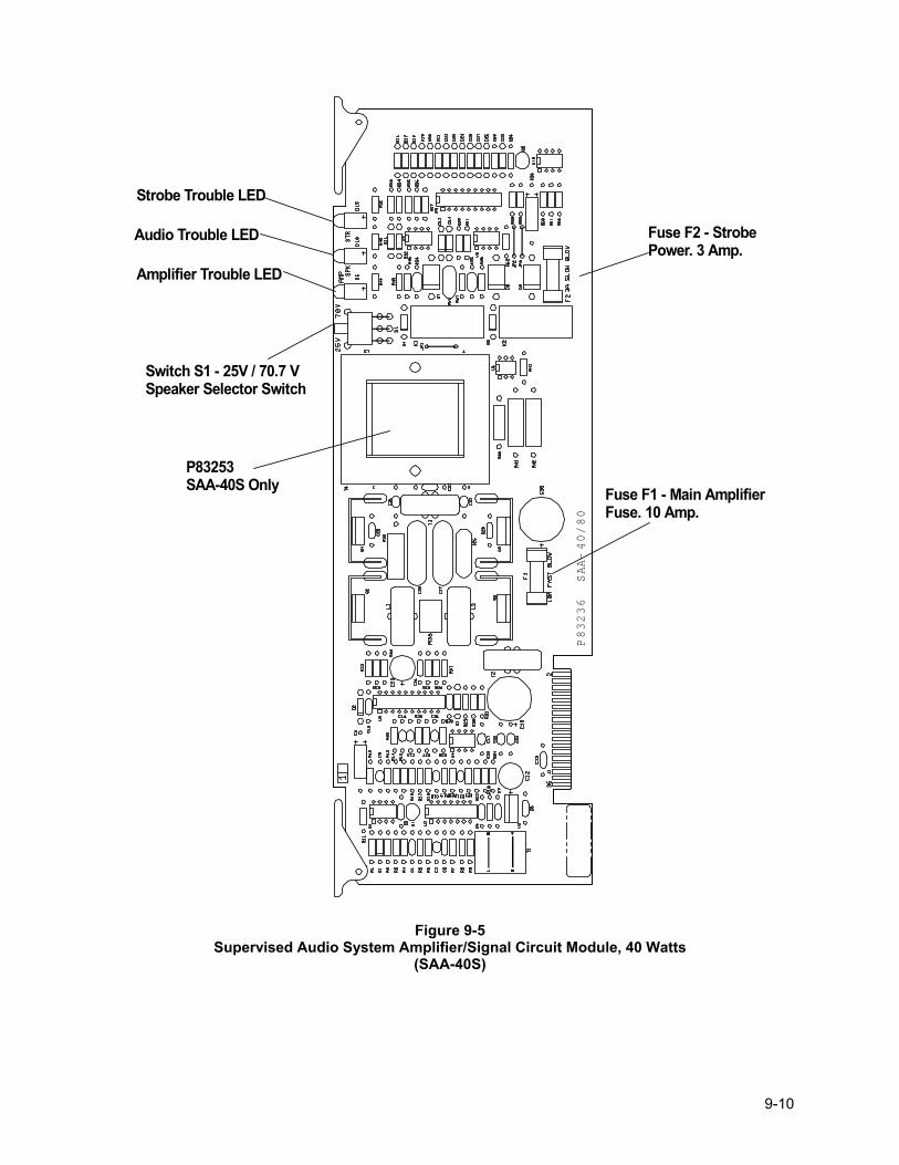
9-10
Fuse F1 - Main AmplifierFuse. 10 Amp.
P83236 SAA-40/80
P83253SAA-40S Only
Fuse F2 - StrobePower. 3 Amp.
Switch S1 - 25V / 70.7 VSpeaker Selector Switch
Strobe Trouble LED
Audio Trouble LED
Amplifier Trouble LED
Figure 9-5
Supervised Audio System Amplifier/Signal Circuit Module, 40 Watts (SAA-40S)
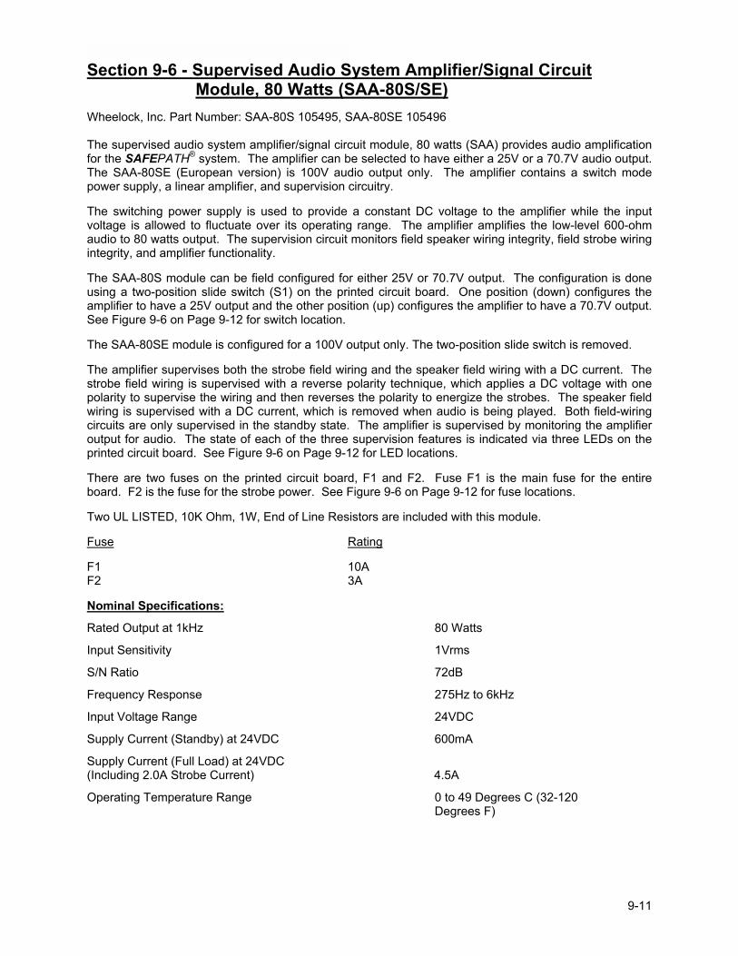
9-11
Section 9-6 - Supervised Audio System Amplifier/Signal Circuit Module, 80 Watts (SAA-80S/SE)
Wheelock, Inc. Part Number: SAA-80S 105495, SAA-80SE 105496 The supervised audio system amplifier/signal circuit module, 80 watts (SAA) provides audio amplification for the SAFEPATH® system. The amplifier can be selected to have either a 25V or a 70.7V audio output. The SAA-80SE (European version) is 100V audio output only. The amplifier contains a switch mode power supply, a linear amplifier, and supervision circuitry. The switching power supply is used to provide a constant DC voltage to the amplifier while the input voltage is allowed to fluctuate over its operating range. The amplifier amplifies the low-level 600-ohm audio to 80 watts output. The supervision circuit monitors field speaker wiring integrity, field strobe wiring integrity, and amplifier functionality. The SAA-80S module can be field configured for either 25V or 70.7V output. The configuration is done using a two-position slide switch (S1) on the printed circuit board. One position (down) configures the amplifier to have a 25V output and the other position (up) configures the amplifier to have a 70.7V output. See Figure 9-6 on Page 9-12 for switch location. The SAA-80SE module is configured for a 100V output only. The two-position slide switch is removed. The amplifier supervises both the strobe field wiring and the speaker field wiring with a DC current. The strobe field wiring is supervised with a reverse polarity technique, which applies a DC voltage with one polarity to supervise the wiring and then reverses the polarity to energize the strobes. The speaker field wiring is supervised with a DC current, which is removed when audio is being played. Both field-wiring circuits are only supervised in the standby state. The amplifier is supervised by monitoring the amplifier output for audio. The state of each of the three supervision features is indicated via three LEDs on the printed circuit board. See Figure 9-6 on Page 9-12 for LED locations. There are two fuses on the printed circuit board, F1 and F2. Fuse F1 is the main fuse for the entire board. F2 is the fuse for the strobe power. See Figure 9-6 on Page 9-12 for fuse locations. Two UL LISTED, 10K Ohm, 1W, End of Line Resistors are included with this module. Fuse Rating F1 10A F2 3A Nominal Specifications:
Rated Output at 1kHz 80 Watts
Input Sensitivity 1Vrms S/N Ratio 72dB
Frequency Response 275Hz to 6kHz
Input Voltage Range 24VDC
Supply Current (Standby) at 24VDC 600mA
Supply Current (Full Load) at 24VDC (Including 2.0A Strobe Current) 4.5A
Operating Temperature Range 0 to 49 Degrees C (32-120 Degrees F)
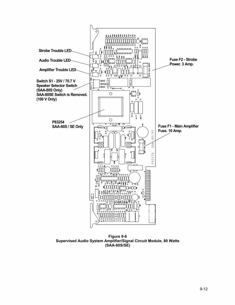
9-12
Fuse F1 - Main AmplifierFuse. 10 Amp.
P83236 SAA-40/80
P83254SAA-80S / SE Only
Fuse F2 - StrobePower. 3 Amp.
Switch S1 - 25V / 70.7 VSpeaker Selector Switch(SAA-80S Only)SAA-80SE Switch is Removed.(100 V Only)
Strobe Trouble LED
Audio Trouble LED
Amplifier Trouble LED
Figure 9-6
Supervised Audio System Amplifier/Signal Circuit Module, 80 Watts (SAA-80S/SE)
9-13
Section 9-7 - Supervised Audio Line Level Module (SALL-15S) Wheelock, Inc. Part Number: 105497 The Supervised Audio Line Level Module (SALL-15S) provides audio output for the SAFEPATH system. The circuit module has a 0.5Vrms, 15 ohm audio NAC circuit, a 24VDC, 2A speaker amplifier power output, and a 24VDC, 2A strobe NAC Circuit. The circuit module contains a linear amplifier and supervision circuitry. The module supervises the strobe NAC circuit field wiring, the speaker amplifier audio field wiring, the speaker amplifier power NAC circuit field wiring, and the amplifier. The strobe NAC circuit field wiring and the speaker amplifier power wiring are supervised with a reverse polarity technique, which applies a DC voltage with one polarity to supervise the wiring and then reverses the polarity to energize the strobe NAC circuit. The speaker amplifier audio NAC circuit field wiring is supervised with a DC current, which is removed when audio is being played. Both field-wiring circuits are only supervised in the standby condition. The amplifier is supervised by monitoring the amplifier output for audio. The state of each of the four supervision features is indicated via four LEDs on the printed circuit board. See Figure 9-7 on Page 9-14 for LED locations. There are three fuses on the printed circuit board, F1 and F2, and F3. Fuse F1 is the fuse for the strobe NAC circuit. F2 is the fuse for the speaker amplifier power. F3 is the main fuse for the entire board. See Figure 9-7 on Page 9-14 for fuse locations. Fuse Rating F1 3A F2 3A F3 6A Nominal Specifications: Rated Output at 1kHz 500m Vrms, 30 ohm load Input Sensitivity 1Vrms S/N Ratio -75dB Frequency Response 275Hz to 4kHz Input Voltage 24VDC Supply Current (Idle) at 24VDC 50mA Supply Current (Full Load) at 24VDC 135mA Operating Temperature Range 0 to 49 Degrees C (32-120 Degrees F) Humidity Range 0 to 85%, Non-condensing
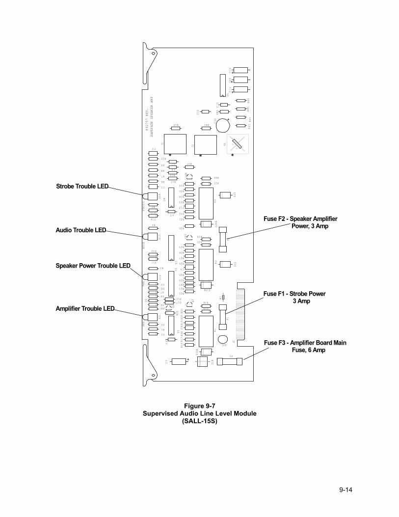
9-14
T1 T3
U3
C15
U1
C3
1 Q1
C8
C9
C1
C2
C10
C14
C16
J1
C11
D15
D8
D9
D21
D19
D20
D1
D2
D11
D14
D12
D3
D10
D13
D16
K1
K3
K2
R32
R31
R33
R34
R35
R40
R38
R18
R19R20
R17
R16
R39
R28
R27
R26
R25
R24
R43
R46
R44
R45
R41
R42
R6
R7 R14
R8
R9
R15
R10
R11
R29
R21
R36
R30
R22
R37
R13
R1
R3
R4
R5
R23
U4
1Q4
1
1Q3
D18
C6
C13
C5
C4
C7
U5
RV1
F1F2
F3
C12
T2
P82757 REV.
SAF
EPATH SPEAK
ER AM
P
STR
OBE
AUDIO
PWR
AMP
D18A
D19A
D20A
D22
D23
R47
R2D4
D6
D7
D5
U2
D17R12
Q2 W
1Fuse F2 - Speaker Amplifier Power, 3 Amp
Fuse F1 - Strobe Power 3 Amp
Fuse F3 - Amplifier Board Main Fuse, 6 Amp
Strobe Trouble LED
Audio Trouble LED
Speaker Power Trouble LED
Amplifier Trouble LED
Figure 9-7 Supervised Audio Line Level Module
(SALL-15S)
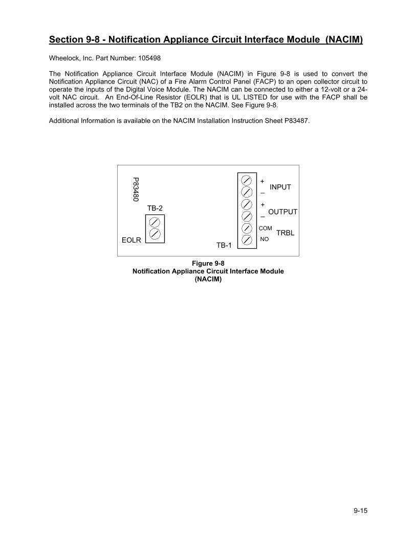
9-15
Section 9-8 - Notification Appliance Circuit Interface Module (NACIM) Wheelock, Inc. Part Number: 105498 The Notification Appliance Circuit Interface Module (NACIM) in Figure 9-8 is used to convert the Notification Appliance Circuit (NAC) of a Fire Alarm Control Panel (FACP) to an open collector circuit to operate the inputs of the Digital Voice Module. The NACIM can be connected to either a 12-volt or a 24-volt NAC circuit. An End-Of-Line Resistor (EOLR) that is UL LISTED for use with the FACP shall be installed across the two terminals of the TB2 on the NACIM. See Figure 9-8. Additional Information is available on the NACIM Installation Instruction Sheet P83487.
EOLRTB-1
TB-2
INPUT
OUTPUT
TRBLCOM
NO
P83480
+
_+
_
Figure 9-8
Notification Appliance Circuit Interface Module (NACIM)
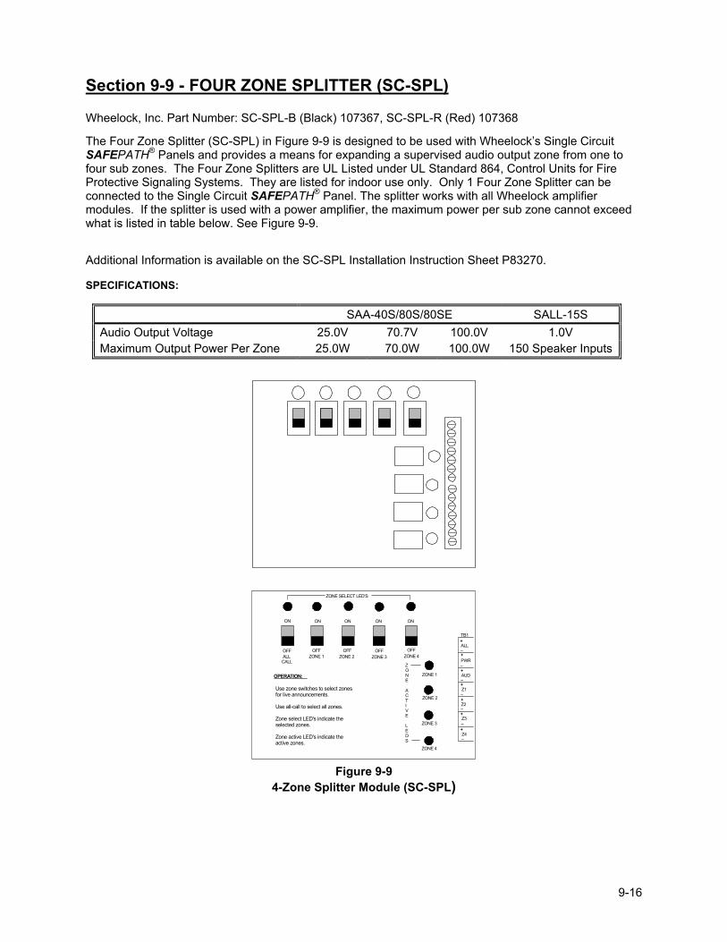
9-16
Section 9-9 - FOUR ZONE SPLITTER (SC-SPL)
Wheelock, Inc. Part Number: SC-SPL-B (Black) 107367, SC-SPL-R (Red) 107368
The Four Zone Splitter (SC-SPL) in Figure 9-9 is designed to be used with Wheelock�s Single Circuit SAFEPATH® Panels and provides a means for expanding a supervised audio output zone from one to four sub zones. The Four Zone Splitters are UL Listed under UL Standard 864, Control Units for Fire Protective Signaling Systems. They are listed for indoor use only. Only 1 Four Zone Splitter can be connected to the Single Circuit SAFEPATH® Panel. The splitter works with all Wheelock amplifier modules. If the splitter is used with a power amplifier, the maximum power per sub zone cannot exceed what is listed in table below. See Figure 9-9.
Additional Information is available on the SC-SPL Installation Instruction Sheet P83270. SPECIFICATIONS:
SAA-40S/80S/80SE SALL-15S Audio Output Voltage 25.0V 70.7V 100.0V 1.0V Maximum Output Power Per Zone 25.0W 70.0W 100.0W 150 Speaker Inputs
ZONE SELECT LED'S
ON
OFF
ON ON
OFF OFF
ON
OFF
ON
OFF ALL CALL
ZONE 1 ZONE 2 ZONE 3 ZONE 4
ZONE 1
ZONE 2
ZONE 3
ZONE 4
ZONE
ACTIVE
LEDS
Z4
Z3
Z2
Z1
AUD
PWR
ALL
TB1
+
_+_
+_+_
+_
+
_
+_
OPERATION:
Use zone switches to select zonesfor live announcements.
Use all-call to select all zones.
Zone select LED's indicate theselected zones.
Zone active LED's indicate theactive zones.
Figure 9-9
4-Zone Splitter Module (SC-SPL)
9-17
Section 9-10 - Auxiliary Input Module (AIM-3) Wheelock, Inc. Part Number: 107387 The Auxiliary Input Module (AIM-3) is an outboard module for use with the SAFEPATH® Panels to expand the number of optional Remote Microphone Stations from one to three. It also has the capability of using one of the Remote Microphone Inputs to connect to a telephone system page port. See Figure 9-10 on Page 9-18. Additional information is available on the AIM-3 Installation Instruction Sheet P83667. Electrical Input Voltage 24VDC Input Current 100 mA Telephone Page 60 mA RMS Page 40 mA Standby Audio Input 1Vrms Dimensions (H x W x D) 13.0� x 7.6� x 2.15� (33cm x 19.4cm x 5.4cm)
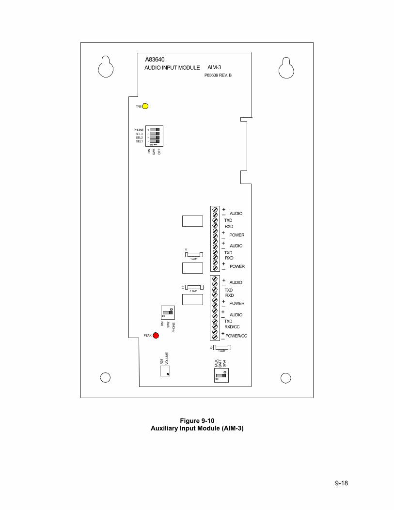
9-18
12
34
ON
1
2
1
2
TALK
BATT
SW4
.1 AMP
F3
R58
VOLU
ME
RM SW2
PHO
NE
PEAK
TRB
SEL3SEL2SEL1
PHONE
ON
SW1
OFF
.1 AMP
.1 AMP
F2F1
+_ AUDIOTXDRXD
POWER
+_
+_
+_
+_
+_+_
+_
AUDIO
AUDIO
AUDIO
TXD
TXD
TXD
RXD
RXD
RXD/CC
POWER
POWER
POWER/CC
A83640AUDIO INPUT MODULE AIM-3
P83639 REV. B
Figure 9-10 Auxiliary Input Module (AIM-3)
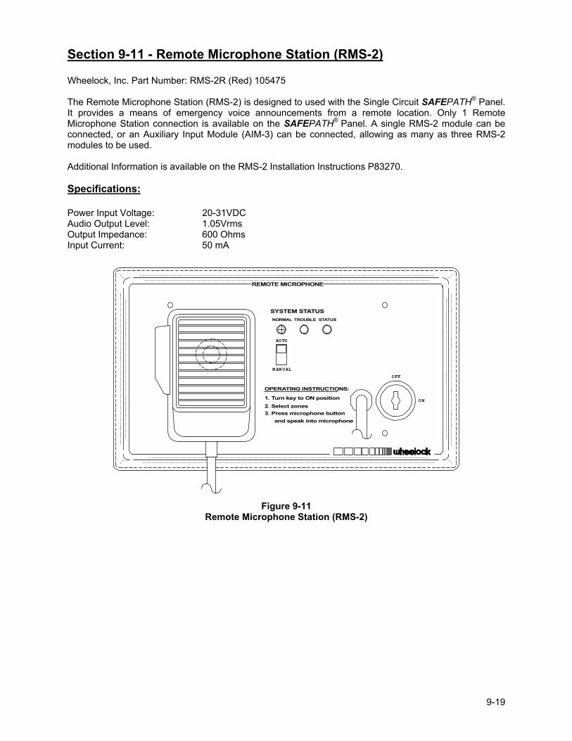
9-19
Section 9-11 - Remote Microphone Station (RMS-2) Wheelock, Inc. Part Number: RMS-2R (Red) 105475 The Remote Microphone Station (RMS-2) is designed to used with the Single Circuit SAFEPATH® Panel. It provides a means of emergency voice announcements from a remote location. Only 1 Remote Microphone Station connection is available on the SAFEPATH® Panel. A single RMS-2 module can be connected, or an Auxiliary Input Module (AIM-3) can be connected, allowing as many as three RMS-2 modules to be used. Additional Information is available on the RMS-2 Installation Instructions P83270. Specifications: Power Input Voltage: 20-31VDC Audio Output Level: 1.05Vrms Output Impedance: 600 Ohms Input Current: 50 mA
3. Press microphone buttonand speak into microphone
1. Turn key to ON position
OPERATING INSTRUCTIONS:
M ANUAL
OFF
ON
SYSTEM STATUSNORMAL
AUTO
TROUBLE
REMOTE MICROPHONE
STATUS
2. Select zones
Figure 9-11
Remote Microphone Station (RMS-2)

9-20
Intentionally Blank
10-1
Chapter 10 - MEA and Warranty Recommendations - That the above units be accepted on condition that all uses, configurations, arrangements and functions, locations and installations comply with the New York City Building Code, specifically Subchapter 17 and with the Referenced Standard RS 17-3 through 17-3C including the NFPA as appropriate, the UL Listing, the manufacturer�s instructions, the Fire Department Rules and the Electrical Code of the City of New York, and on further condition that: (a) The use, installation and application of the SAFEPATH® System shall be restricted exclusively to connection
with an BSA/MEA approved compatible Class E, Class J or Class C Fire Command Station. (b) The Fire Command Station shall have the capability of overriding any function of the SAFEPATH® System. (c) Prior to the installation of any SAFEPATH® System, a specific approval for a specific installation must be
obtained from the Fire Department. (d) A priority voice message matrix must be submitted to the Fir Department for approval before the installation is
performed and shall include the following information:
1. The duration of each message. 2. The content of each message. 3. The duration of the audible and visual alarm signals prior to the initiation of the subsequent prerecorded
message transmission. 4. The interval between the cessation of the audible and visual alarm signals and the generation of
prerecorded message.
(e) The SAFEPATH® Panel must be located in the room as, and within 20 feet of a BSA/MEA approved Fire Command Station. The wiring between the SAFEPATH® Panel Control Unit and the Fire Command Station must be enclosed in conduit.
(f) Power supply wiring to the SAFEPATH® Panel Control Unit shall be installed in the same conduit containing the
input and output wiring. (g) When used with central office communicator or transmitter, the installation and operation of the equipment and
devices listed herein shall comply with Fire Department Rule #3 - RCNY 17-01, NFPA 71, and shall have the capability of transmitting separate and distinct signals to indicate manual pull station alarm, automatic smoke/heat detection alarm, sprinkler waterflow alarm, supervisory signal indications and trouble indications.
(h) The connection of security/burglar devices and equipment to that submitted for acceptance for fire alarm usage
under this MEA application is prohibited within New York City and such equipment and devices shall be so permanently labeled.
All shipments and deliveries of such equipment shall be provided with a metal tag suitably placed, certifying that the equipment shipped or delivered is equivalent to that tested and accepted for use, as provided for in Section 27-131 of the Building Code.
10-2
Limited Warranty
Wheelock products must be used within their published specifications and must be PROPERLY specified, applied, installed, operated, maintained and operationally tested in accordance with these instructions at the time of installation and at least twice a year or more often and in accordance with local, state and federal codes, regulations and laws. Specification, application, installation, operation, maintenance and testing must be performed by qualified personnel for proper operation in accordance with all of the latest National Fire Protection Association (NFPA), Underwriters' Laboratories (UL), Underwriters� Laboratories of Canada (ULC), National Electrical Code (NEC), Occupational Safety and Health Administration (OSHA), local, state, county, province, district, federal and other applicable building and fire standards, guidelines, regulations, laws and codes including, but not limited to, all appendices and amendments and the requirements of the local authority having jurisdiction (AHJ). Wheelock products when properly specified, applied, installed, operated, maintained and operationally tested as provided above are warranted against mechanical and electrical defects for a period of three years from date of manufacture (as determined by date code. Correction of defects by repair or replacement shall be at Wheelock's sole discretion and shall constitute fulfillment of all obligations under this warranty. THE FOREGOING LIMITED WARRANTY SHALL IMMEDIATELY TERMINATE IN THE EVENT ANY PART NOT FURNISHED BY WHEELOCK IS INSTALLED IN THE PRODUCT. THE FOREGOING LIMITED WARRANTY SPECIFICALLY EXCLUDES ANY SOFTWARE REQUIRED FOR THE OPERATION OF OR INCLUDED IN A PRODUCT. WHEELOCK MAKES NO REPRESENTATION OR WARRANTY OF ANY OTHER KIND, EXPRESS, IMPLIED OR STATUTORY WHETHER AS TO MERCHANTABILITY, FITNESS FOR A PARTICULAR PURPOSE OR ANY OTHER MATTER.
USERS ARE SOLELY RESPONSIBLE FOR DETERMINING WHETHER A PRODUCT IS SUITABLE FOR THE USER'S PURPOSES, OR WHETHER IT WILL ACHIEVE THE USER'S INTENDED RESULTS. THERE IS NO WARRANTY AGAINST DAMAGE RESULTING FROM MISAPPLICATION, IMPROPER SPECIFICATION, ABUSE, ACCIDENT OR OTHER OPERATING CONDITIONS BEYOND WHEELOCK'S CONTROL.
SOME WHEELOCK PRODUCTS CONTAIN SOFTWARE. WITH RESPECT TO THOSE PRODUCTS, WHEELOCK DOES NOT WARRANTY THAT THE OPERATION OF THE SOFTWARE WILL BE UNINTERRUPTED OR ERROR-FREE OR THAT THE SOFTWARE WILL MEET ANY OTHER STANDARD OF PERFORMANCE, OR THAT THE FUNCTIONS OR PERFORMANCE OF THE SOFTWARE WILL MEET THE USER'S REQUIREMENTS. WHEELOCK SHALL NOT BE LIABLE FOR ANY DELAYS, BREAKDOWNS, INTERRUPTIONS, LOSS, DESTRUCTION, ALTERATION, OR OTHER PROBLEMS IN THE USE OF A PRODUCT ARISING OUT OF OR CAUSED BY THE SOFTWARE.
THE LIABILITY OF WHEELOCK ARISING OUT OF THE SUPPLYING OF A PRODUCT, OR ITS USE, WHETHER ON WARRANTIES, NEGLIGENCE, OR OTHERWISE, SHALL NOT IN ANY CASE EXCEED THE COST OF CORRECTING DEFECTS AS STATED IN THE LIMITED WARRANTY AND UPON EXPIRATION OF THE WARRANTY PERIOD ALL SUCH LIABILITY SHALL TERMINATE. WHEELOCK IS NOT LIABLE FOR LABOR COSTS INCURRED IN REMOVAL, REINSTALLATION OR REPAIR OF THE PRODUCT BY ANYONE OTHER THAN WHEELOCK OR FOR DAMAGE OF ANY TYPE WHATSOEVER, INCLUDING BUT NOT LIMITED TO, LOSS OF PROFIT OR INCIDENTAL OR CONSEQUENTIAL DAMAGES. THE FOREGOING SHALL CONSTITUTE THE SOLE REMEDY OF THE PURCHASER AND THE EXCLUSIVE LIABILITY OF WHEELOCK.
IN NO CASE WILL WHEELOCK'S LIABILITY EXCEED THE PURCHASE PRICE PAID FOR A PRODUCT.
Limitation of Liability
WHEELOCK'S LIABILITY ON ANY CLAIM OF ANY KIND, INCLUDING NEGLIGENCE AND BREACH OF WARRANTY, FOR ANY LOSS OR DAMAGE RESULTING FROM, ARISING OUT OF, OR CONNECTED WITH THIS CONTRACT, OR FROM THE MANUFACTURE, SALE, DELIVERY, RESALE, REPAIR OR USE OF ANY PRODUCT COVERED BY THIS ORDER SHALL BE LIMITED TO THE PRICE APPLICABLE TO THE PRODUCT OR PART THEREOF WHICH GIVES RISE TO THE CLAIM. WHEELOCK'S LIABILITY ON ANY CLAIM OF ANY KIND SHALL CEASE IMMEDIATELY UPON THE INSTALLATION IN THE PRODUCT OF ANY PART NOT FURNISHED BY WHEELOCK. IN NO EVENT SHALL WHEELOCK BE LIABLE FOR ANY CLAIM OF ANY KIND UNLESS IT IS PROVEN THAT OUR PRODUCT WAS A DIRECT CAUSE OF SUCH CLAIM. FURTHER, IN NO EVENT, INCLUDING IN THE CASE OF A CLAIM OF NEGLIGENCE, SHALL WHEELOCK BE LIABLE FOR INCIDENTAL OR CONSEQUENTIAL DAMAGES. SOME STATES DO NOT ALLOW THE EXCLUSION OR LIMITATION OF INCIDENTAL OR CONSEQUENTIAL DAMAGES, SO THE PRECEEDING LIMITATION MAY NOT APPLY TO ALL PURCHASERS.
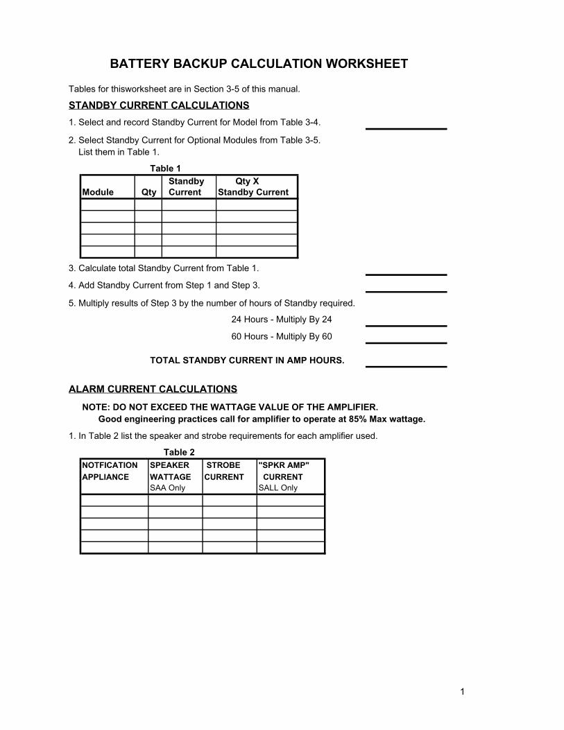
1
BATTERY BACKUP CALCULATION WORKSHEET
Tables for thisworksheet are in Section 3-5 of this manual.
STANDBY CURRENT CALCULATIONS1. Select and record Standby Current for Model from Table 3-4.
2. Select Standby Current for Optional Modules from Table 3-5. List them in Table 1.
Table 1 Standby Qty X
Module Qty Current Standby Current
3. Calculate total Standby Current from Table 1.
4. Add Standby Current from Step 1 and Step 3.
5. Multiply results of Step 3 by the number of hours of Standby required.
24 Hours - Multiply By 24
60 Hours - Multiply By 60
TOTAL STANDBY CURRENT IN AMP HOURS.
ALARM CURRENT CALCULATIONSNOTE: DO NOT EXCEED THE WATTAGE VALUE OF THE AMPLIFIER.
Good engineering practices call for amplifier to operate at 85% Max wattage.
1. In Table 2 list the speaker and strobe requirements for each amplifier used.
Table 2NOTFICATION SPEAKER STROBE "SPKR AMP"APPLIANCE WATTAGE CURRENT CURRENT
SAA Only SALL Only
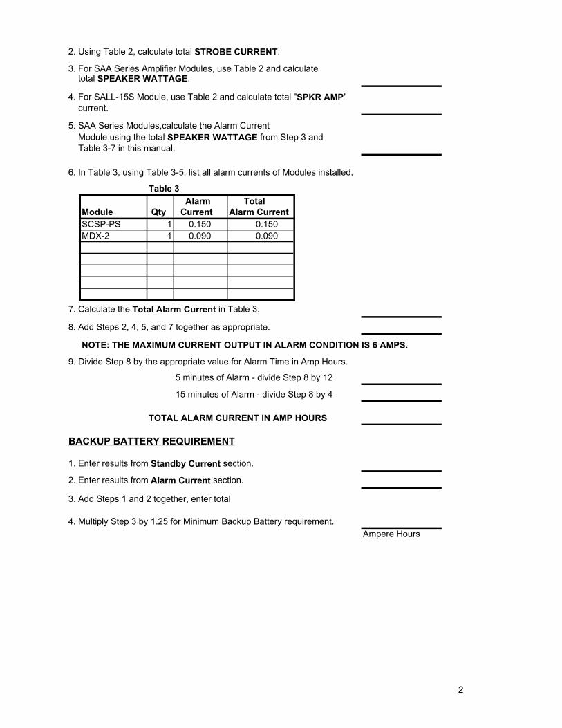
2
2. Using Table 2, calculate total STROBE CURRENT.
3. For SAA Series Amplifier Modules, use Table 2 and calculate total SPEAKER WATTAGE.
4. For SALL-15S Module, use Table 2 and calculate total "SPKR AMP" current.
5. SAA Series Modules,calculate the Alarm Current Module using the total SPEAKER WATTAGE from Step 3 and Table 3-7 in this manual.
6. In Table 3, using Table 3-5, list all alarm currents of Modules installed.
Table 3 Alarm Total
Module Qty Current Alarm CurrentSCSP-PS 1 0.150 0.150MDX-2 1 0.090 0.090
7. Calculate the Total Alarm Current in Table 3.
8. Add Steps 2, 4, 5, and 7 together as appropriate.
NOTE: THE MAXIMUM CURRENT OUTPUT IN ALARM CONDITION IS 6 AMPS.
9. Divide Step 8 by the appropriate value for Alarm Time in Amp Hours.
5 minutes of Alarm - divide Step 8 by 12
15 minutes of Alarm - divide Step 8 by 4
TOTAL ALARM CURRENT IN AMP HOURS
BACKUP BATTERY REQUIREMENT
1. Enter results from Standby Current section.
2. Enter results from Alarm Current section.
3. Add Steps 1 and 2 together, enter total
4. Multiply Step 3 by 1.25 for Minimum Backup Battery requirement.Ampere Hours