Embed Size (px)
Citation preview
Intelligen
t Com
pletions
Intelligent CompletionsHalliburton Intelligent Completions is the world's leading
provider of intelligent technology to the upstream oil
industry. First introduced in 1997, SmartWell® system
technology was the industry's first intelligent well completion
system and was designed specifically to remotely control and
monitor specific reservoir zones.
Today, Halliburton Intelligent Completions offers a broad
complement of products and services that range from
reservoir engineering studies to advanced completion design,
zonal isolation and flow control, reservoir monitoring, and
surface digital infrastructure solutions.
SmartWell® Systems
A SmartWell completion system optimizes production
by collecting, transmitting, and analyzing completion,
production, and reservoir data; allowing remote selective
zonal control and ultimately maximizing reservoir
efficiency by:
• Helping increase production – Commingling of
production from different reservoir zones increases and
accelerates production and shortens field life.
• Helping increase ultimate recovery – Selective zonal
control enables effective management of water injection,
gas and water breakthrough, and individual zone
productivity.
• Helping reduce capital expenditure – The ability to
produce from multiple reservoirs through a single
wellbore reduces the number of wells required for field
development, thereby lowering drilling and completion
costs. Size and complexity of surface handling facilities
are reduced by managing water through remote
zonal control.
• Helping reduce operating expenditure – Remote
configuration of wells optimizes production without
costly well intervention. In addition, commingling of
production from different reservoir zones shortens field
life, thereby reducing operating expenditures.
SmartWell systems are designed to meet the demands of
every intelligent completion in all global areas and
environments. Halliburton Intelligent Completions has
designed its product lines and solutions accordingly.
• Flow control solutions include interval control valves
(ICV), lubricator valves (LV), packers, and downhole
control systems.
• Permanent monitoring solutions include downhole
gauges and flowmeters.
• Digital infrastructure solutions include a supervisory
control and systems designed for manual, automatic, and
integrated operation and electro-hydraulic control and
monitoring systems.
• Optical fiber solutions include distributed temperature
sensing (DTS) tools and software.
Reliability
Reliability is essential for intelligent completion systems, and
Halliburton engineers reliability into all of its equipment.
The company is ISO 9001 application certified and has
developed processes to guide, monitor, and optimize system
delivery and performance. In addition, Halliburton has a
dedicated Reliability Assurance department that manages
reliability tools and processes.
Halliburton maintains a detailed database to track the field
performance of each SmartWell system installation. The
knowledge gleaned from this data is used to calibrate design
predictions and optimize the design and production process.
Intelligent Completions 3-1
Flow Control Valves
Halliburton Intelligent Completions offers interval control
valves (ICV) both with and without shrouds and deflectors:
• HS-ICV – Interval control valve for deepwater and high-
pressure/high-temperature applications
• MCC-ICV – Cost-effective valve with choking capability
• LV-ICV – Lubricator valve
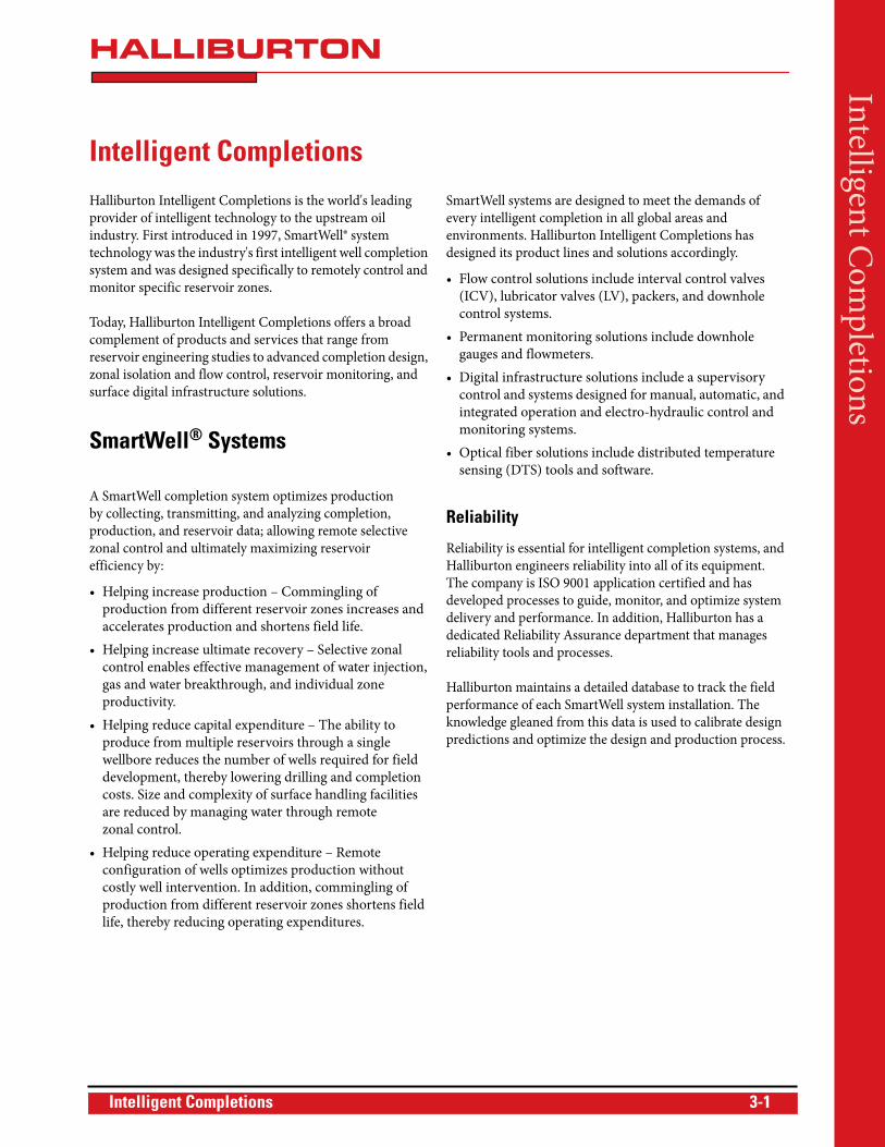
HS-ICV Valve
The HS interval control valve is the next-generation
downhole control valve designed for Halliburton’s industry-
leading SmartWell® intelligent completion systems. The HS-
ICV is designed for deepwater and high-pressure/high-
temperature (HP/HT) applications in which operating
conditions are extremely severe.
The HS-ICV's eight-position standard gas/liquid flow trims
have been characterized to provide optimum production/
injection at various positions. Optional onboard sensors
track the movement of the flow trim. These position sensors
provide the operator with real-time feedback to confirm
valve movements.
Features• Proprietary, debris-tolerant, metal-to-metal seal
• Customizable gas/liquid flow trim
• Can be used in simple on/off intervention avoidance
applications or in more versatile advanced reservoir
management choking applications with the
Accu-Pulse™module
Benefits• Remotely control flow into or out of the reservoir in
challenging environments such as deepwater and HP/HT
• Eliminate the potential for wellbore debris to be trapped
inside the tool and consequently prevent valve
movement or impact sealing integrity
• Obtain real-time confirmation of remotely actuated
valve movements using optional position sensors
• Unload at a maximum differential pressure of 5,000 psi
without the threat of any valve damage—the highest
unloading capacity in the industry
HA
L30
642
3-2 Intelligent Completions
OperationHydraulically actuated, the HS-ICV is operated remotely
from surface using Halliburton Intelligent Completions’
reliable Direct Hydraulics, Digital Hydraulics™, or SmartPlex™
downhole control system. The premium thermoplastic
hydraulic chamber seals are designed to operate under high
actuation pressures and temperatures. The valve has also been
subjected to a stringent qualification program, including
temperature, pressure, debris, and erosion tests.
The HS-ICV body has slots to accommodate two 1/4-in.
dedicated instrument wires for position sensors and allows
bypass of up to six 1/4-in. bare hydraulic control lines or
instrument wires—all without compromising valve body
rating or working envelope.
Debris-Tolerant DesignThe HS-ICV has been designed and tested such that the flow
trim will ensure complete metal-to-metal (MTM) seal
integrity even when exposed to heavy wellbore debris. A one-
piece valve mandrel design eliminates the potential for
wellbore debris to be trapped inside the tool and consequently
prevent valve movement.
Proprietary MTM SealThe HS-ICV houses a proprietary metal-to-metal flank seal
that enables the valve to unload at a maximum differential
pressure of 5,000 psi without the threat of any valve damage.
Any additional tubing or annulus pressure acts on the MTM
seal to further ensure seal integrity, which has been
rigorously tested and qualified at low and high-pressure (up
to 10,000 psi) differentials.
Pressure-Balanced Valve MandrelA pressure-balanced valve mandrel design eliminates the
need for a latch mechanism to hold trim closed or the need to
maintain hydraulic pressure on the close chamber to keep the
flow trim shut. This balanced sleeve design also prevents
drifting of the sleeve in the incrementally open position.
Mandrel design also includes a shifting profile that allows the
sleeve to be mechanically shifted in the event hydraulic
control has been compromised or if sleeve momentum is not
achievable due to scale buildup inside the ICV.
Available in Three Variants• HSP Premium Choking ICV designed for more
advanced reservoir management when used in
conjunction with SCRAMS® Surface Controlled
Reservoir Analysis downhole control system
• HSB Base Choking ICV designed for more versatile
choking applications when used in conjunction with the
Accu-Pulse™ incremental positioning module
• HSO designed for simple on/off applications
The flow trims on the HSB and HSP ICV can be customized
to suit a particular well’s injection or production philosophy.
Tungsten carbide is the material of choice for these flow trims
to combat the threat of erosion due to high flow rates.
Shrouded VersionsA shrouded configuration of the HS-ICV is available
primarily for a two-zone stacked gravel pack application. The
shrouds can also be shrink-fitted with a carbide insert when
the valve is used in a stacked gravel pack injection application.
Deflector VersionThis configuration of the HS-ICV is available primarily for
high rate gas or water injection applications. The deflectors
are lined with tungsten carbide inserts to prevent erosional
effects as a result of impingement from high flow velocity
exiting the valve flow trim.
Intelligent Completions 3-3
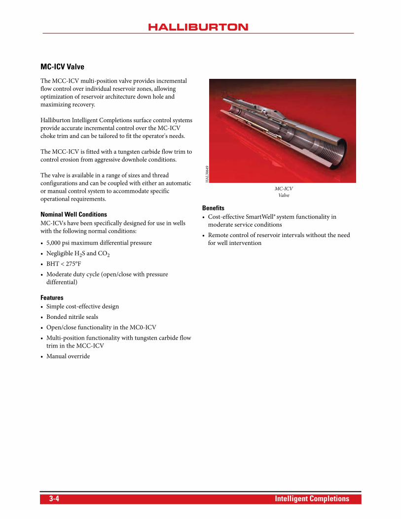
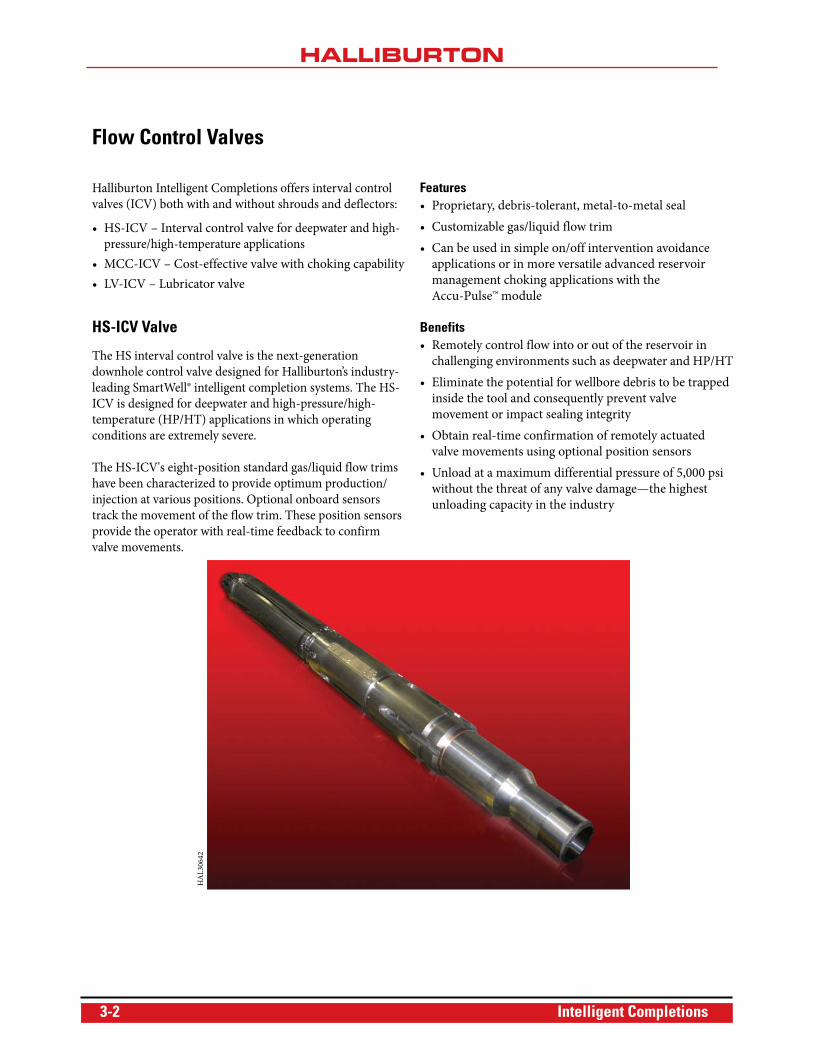
MC-ICV Valve
The MCC-ICV multi-position valve provides incremental
flow control over individual reservoir zones, allowing
optimization of reservoir architecture down hole and
maximizing recovery.
Halliburton Intelligent Completions surface control systems
provide accurate incremental control over the MC-ICV
choke trim and can be tailored to fit the operator's needs.
The MCC-ICV is fitted with a tungsten carbide flow trim to
control erosion from aggressive downhole conditions.
The valve is available in a range of sizes and thread
configurations and can be coupled with either an automatic
or manual control system to accommodate specific
operational requirements.
Nominal Well ConditionsMC-ICVs have been specifically designed for use in wells
with the following normal conditions:
• 5,000 psi maximum differential pressure
• Negligible H2S and CO2
• BHT < 275°F
• Moderate duty cycle (open/close with pressure
differential)
Features• Simple cost-effective design
• Bonded nitrile seals
• Open/close functionality in the MC0-ICV
• Multi-position functionality with tungsten carbide flow
trim in the MCC-ICV
• Manual override
Benefits• Cost-effective SmartWell®system functionality in
moderate service conditions
• Remote control of reservoir intervals without the need
for well intervention
MC-ICV
Valve
HA
L30
649
3-4 Intelligent Completions
Type
Siz
e in
.
Flow
Are
a, O
D o
f HS
- ID
of D
efle
ctor
in. ²
HS
-Ser
ies
2 7 2.58
3 1 6.38
4 1 5.32
5 1 12.49
Notes:a) Chemrab) HS-serc) HS-serd) HS-sere) HS-serf) Please *) Pending
Please co
Chemraz
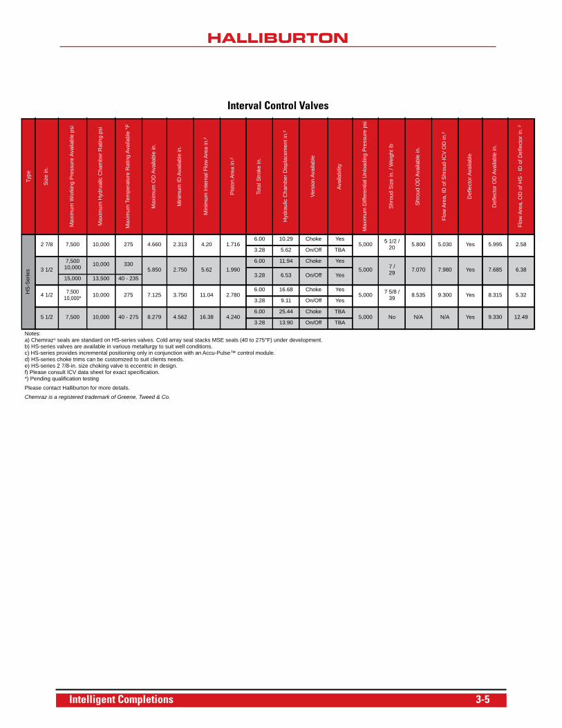
Interval Control Valves
Max
imum
Wor
king
Pre
ssur
e Av
aila
ble
psi
Max
imum
Hyd
rual
ic C
ham
ber R
atin
g ps
i
Max
imum
Tem
pera
ture
Rat
ing
Avai
labl
e °F
Max
imum
OD
Ava
ilabl
e in
.
Min
imum
ID A
vaila
ble
in.
Min
imum
Inte
rnal
Flo
w A
rea
in.²
Pis
ton
Are
a in
.²
Tota
l Stro
ke in
.
Hyd
raul
ic C
ham
ber D
ispl
acem
ent i
n.³
Vers
ion
Avai
labl
e
Avai
labi
lity
Max
imum
Diff
eren
tial U
nloa
ding
Pre
ssur
e ps
i
Shr
oud
Siz
e in
. / W
eigh
t lb
Shr
oud
OD
Ava
ilabl
e in
.
Flow
Are
a, ID
of S
hrou
d-IC
V O
D in
.²
Def
lect
or A
vaila
ble
Def
lect
or O
D A
vaila
ble
in.
/8 7,500 10,000 275 4.660 2.313 4.20 1.7166.00 10.29 Choke Yes
5,000 5 1/2 /20 5.800 5.030 Yes 5.995
3.28 5.62 On/Off TBA
/27,500
10,000 10,000 3305.850 2.750 5.62 1.990
6.00 11.94 Choke Yes5,000 7 /
29 7.070 7.980 Yes 7.6853.28 6.53 On/Off Yes15,000 13,500 40 - 235
/2 7,500 10,000* 10,000 275 7.125 3.750 11.04 2.780
6.00 16.68 Choke Yes5,000 7 5/8 /
39 8.535 9.300 Yes 8.3153.28 9.11 On/Off Yes
/2 7,500 10,000 40 - 275 8.279 4.562 16.38 4.2406.00 25.44 Choke TBA
5,000 No N/A N/A Yes 9.3303.28 13.90 On/Off TBA
z® seals are standard on HS-series valves. Cold array seal stacks MSE seals (40 to 275°F) under development.ies valves are available in various metallurgy to suit well conditions.ies provides incremental positioning only in conjunction with an Accu-Pulse™ control module.ies choke trims can be customized to suit clients needs.ies 2 7/8-in. size choking valve is eccentric in design.consult ICV data sheet for exact specification. qualification testing
ntact Halliburton for more details.
is a registered trademark of Greene, Tweed & Co.
Intelligent Completions 3-5
HS Circulating Valve
The HS Circulating Valve is designed for use in SmartWell®
and conventional completion systems. Based on the proven
HS interval control valve (ICV) design technology, the HS
circulating valve is designed for safe and efficient circulation
of completion fluids after landing the completion and setting
the HF-1 and completion packer.
The HS circulating valve is a bi-directional hydraulically
operated balanced piston valve with a gas tight redundant
sealing mechanism. The sealing mechanism consists of a
debris tolerant metal-to-metal (MTM) primary seal and a
secondary thermoplastic seal array. The valve mandrel
incorporates a carbide nose to prevent erosion of the sealing
surface areas.
Features• Proprietary, debris-tolerant metal-to-metal seal
• Redundant thermoplastic seal ensures gas tight seal
integrity
• Erosion resistant carbide nose seal
• High circulation rates
• Remotely activated without intervention
• Manual override shift profile
• Bypass slots for 12 1/4-in. control lines
Benefits• Run above the production packer, operated after packer
is set, providing improved well control
• Helps eliminate need to circulate across packer element,
reducing risk of damage to element
• Prevents circulation pressures from impacting reservoir
• Faster circulation rates reducing rig time
• Allows for circulating well kill fluid during workover
operations without need to perforating tubing
OperationThe HS circulating valve is placed above the production
packer in the completion string and is run into the well.
For a SmartWell® completion, once on depth, the HF-1
production packer is set via pressure down the production
tubing. Element packoff integrity is then determined by
applying pressure down the annulus. The open line of the
valve is pressured up via the surface control unit to open the
sleeve. Circulation down the annulus or tubing begins.
Higher circulation rates can be attained as fluid is not
circulated past the packer element. Once the desired volumes
have been circulated, the close line of the valve is pressured
up to move the sleeve into the closed position. The tubing is
then pressured up to a maximum of 7,500 psi to test the
sleeve integrity. A zero leak rate should be observed. On
completion of a successful pressure test, the completion
program can progress to the next step.
Field-Proven MTM SealThe HS circulating valve houses a proprietary MTM seal
from the proven HS-ICV design. Any additional tubing or
annulus pressure acts on the seal to further ensure its
integrity. The seal has been rigorously tested and qualified at
low and high-pressure (up to 10,000 psi) differentials.
Redundant Thermoplastic SealThe MTM seal is backed up by a redundant thermoplastic
seal to achieve gas tight sealing integrity. These field-proven
thermoplastic metal energized (MSE) seals are designed for
redundancy in low and high-pressure applications.
The MTM along with the redundant thermoplastic seal have
been qualified to provide a gas tight (zero leak) seal integrity.
Pressure-Balanced Valve MandrelA pressure-balanced valve mandrel design eliminates the
need for a latch mechanism to hold the trim closed or the
need to maintain hydraulic pressure on the close chamber to
keep the flow trim shut. This balanced sleeve design prevents
drifting of the sleeve in the open position. The valve mandrel
design also includes a shifting profile that allows the sleeve to
be mechanically shifted in the event hydraulic control has
been compromised, or if sleeve movement is not achievable
due to scale buildup inside the ICV.
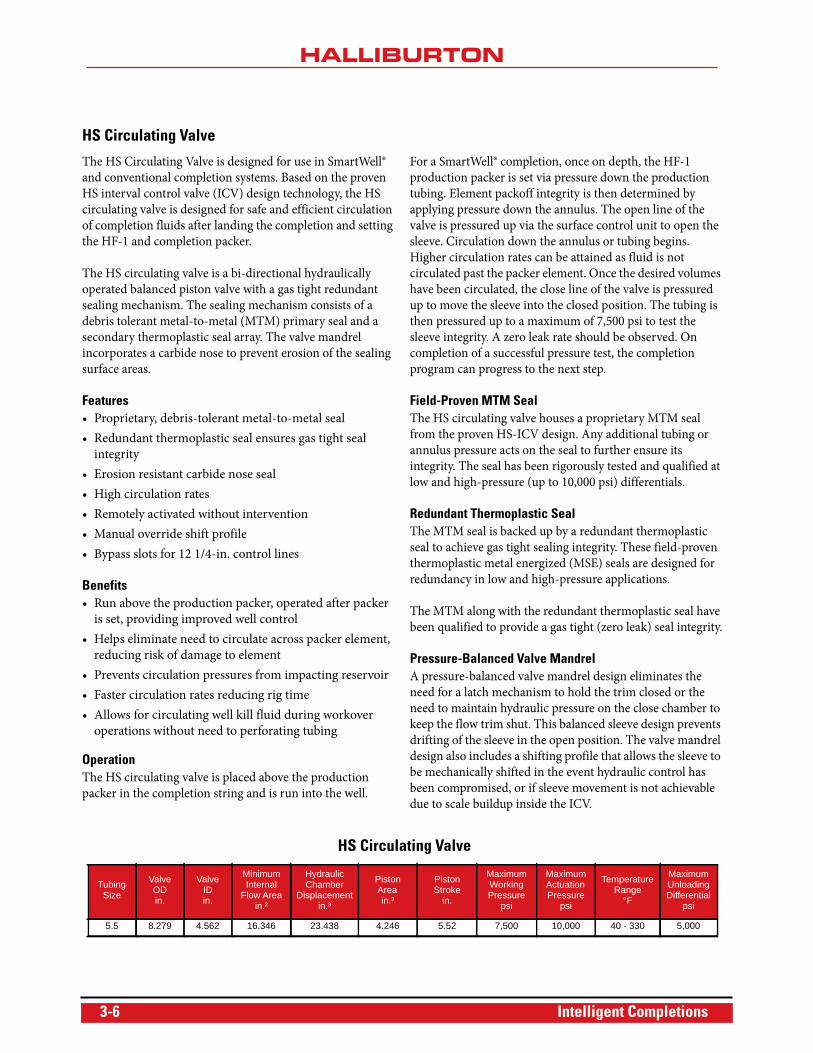
HS Circulating Valve
TubingSize
Valve ODin.
Valve IDin.
Minimum Internal
Flow Areain.²
Hydraulic Chamber
Displacementin.³
Piston Areain.³
Piston Stroke
in.
Maximum Working Pressure
psi
Maximum Actuation Pressure
psi
Temperature Range
°F
Maximum Unloading Differential
psi
5.5 8.279 4.562 16.346 23.438 4.246 5.52 7,500 10,000 40 - 330 5,000
3-6 Intelligent Completions
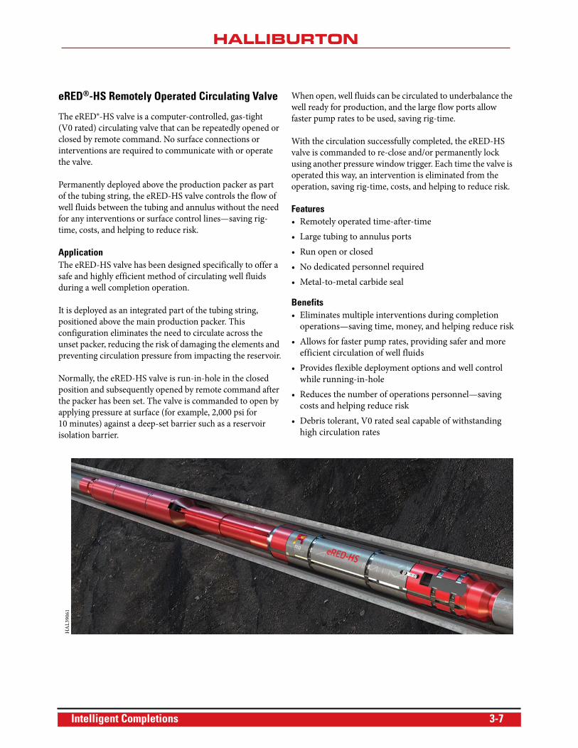
eRED®-HS Remotely Operated Circulating Valve
The eRED®-HS valve is a computer-controlled, gas-tight
(V0 rated) circulating valve that can be repeatedly opened or
closed by remote command. No surface connections or
interventions are required to communicate with or operate
the valve.
Permanently deployed above the production packer as part
of the tubing string, the eRED-HS valve controls the flow of
well fluids between the tubing and annulus without the need
for any interventions or surface control lines—saving rig-
time, costs, and helping to reduce risk.
ApplicationThe eRED-HS valve has been designed specifically to offer a
safe and highly efficient method of circulating well fluids
during a well completion operation.
It is deployed as an integrated part of the tubing string,
positioned above the main production packer. This
configuration eliminates the need to circulate across the
unset packer, reducing the risk of damaging the elements and
preventing circulation pressure from impacting the reservoir.
Normally, the eRED-HS valve is run-in-hole in the closed
position and subsequently opened by remote command after
the packer has been set. The valve is commanded to open by
applying pressure at surface (for example, 2,000 psi for
10 minutes) against a deep-set barrier such as a reservoir
isolation barrier.
When open, well fluids can be circulated to underbalance the
well ready for production, and the large flow ports allow
faster pump rates to be used, saving rig-time.
With the circulation successfully completed, the eRED-HS
valve is commanded to re-close and/or permanently lock
using another pressure window trigger. Each time the valve is
operated this way, an intervention is eliminated from the
operation, saving rig-time, costs, and helping to reduce risk.
Features• Remotely operated time-after-time
• Large tubing to annulus ports
• Run open or closed
• No dedicated personnel required
• Metal-to-metal carbide seal
Benefits• Eliminates multiple interventions during completion
operations—saving time, money, and helping reduce risk
• Allows for faster pump rates, providing safer and more
efficient circulation of well fluids
• Provides flexible deployment options and well control
while running-in-hole
• Reduces the number of operations personnel—saving
costs and helping reduce risk
• Debris tolerant, V0 rated seal capable of withstanding
high circulation rates
HA
L39
061
Intelligent Completions 3-7
OperationThe eRED-HS valve is an integrated assembly of two existing
devices. The first is the eMotion® electronic control unit. This
is used to provide surface communication and the motive
force to operate the second device—a Halliburton HS-ICV
circulating valve.
The assembly has integrated pressure and temperature
sensors which it uses to monitor the well conditions and is
preprogrammed to either open or close whenever a specified
condition (known as a trigger) is detected.
The triggers use a variety of well parameters including
ambient pressure, temperature, time or surface applied
pressure. Each time a trigger is detected the valve will either
open or close as per its instructions. This process can be
repeated time-and-time again without the need for any form
of intervention or any control lines to surface.
Controlling the eRED-HS Valve RemotelyBy applying a defined pressure for a defined time at surface,
the operator can activate the pressure window trigger. This
allows direct communication to the eRED-HS valve so it can
be remotely operated. For example, applying between 1,000
and 1,500 psi for 10 minutes could instruct it to open.
Any pressure applied outside the defined values will be
ignored. This means pressure can be applied to the tubing
(for tubing integrity tests or packer setting, etc.) without any
risk of inadvertent activation.
Onboard data analysis allows the eRED-HS valve to
distinguish its own commands from other external factors
such as naturally fluctuating hydrostatic or reservoir
pressure. This enables the valve to behave as planned even if
the downhole conditions change unexpectedly.
A range of other triggers consisting of ambient well pressure,
ambient well temperature and a timer are also available.
These triggers are used to provide a pre-programmed
sequence for the eRED-HS valve to follow without any input
from the surface.
Each trigger can be used independently or combined to build
more elaborate instructions. For example, the eRED-HS
valve could be set to close when it detects pressure below
2,000 psi, but only after 100 hours downhole. The pressure
window trigger can also be used to manually cancel or
override any trigger or permanently lock the valve in its
current position.
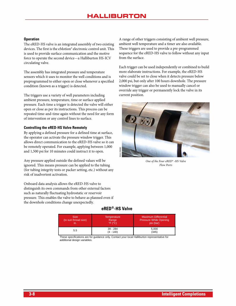
Opening
One of the Four eRED® -HS Valve
Flow Ports
HA
L39
080
eRED®-HS Valve
Size (to suit thread size)
in.
Temperature Range °F (°C)
Maximum Differential Pressure While Opening
psi (bar)
5.5 39 - 284 (4 - 140)
5,000(345)
These specifications are for guidance only. Contact your local Halliburton representative for additional design variables.
3-8 Intelligent Completions
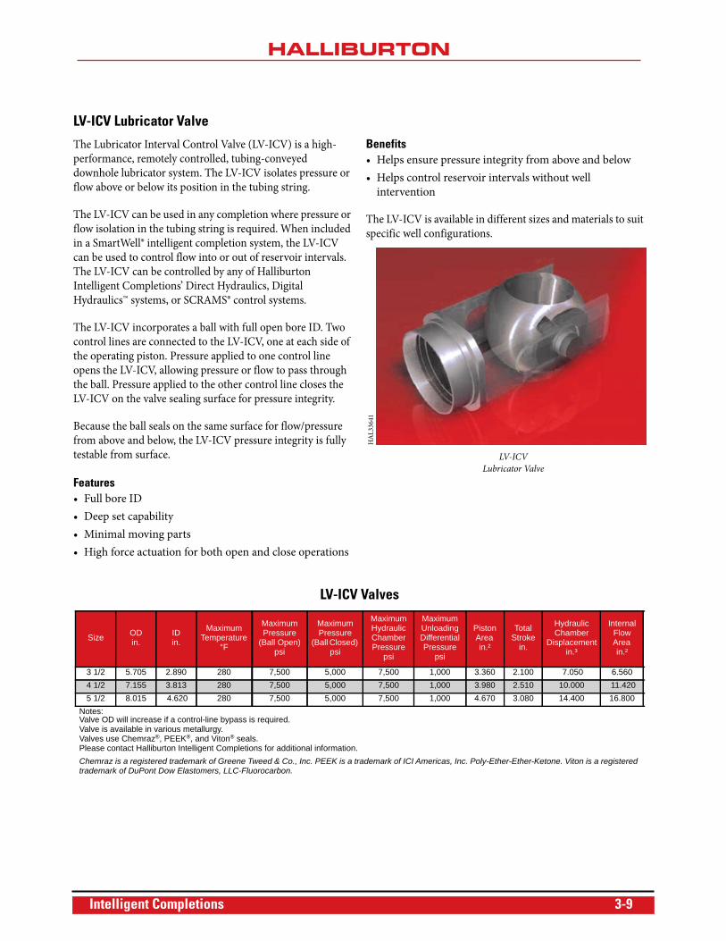
LV-ICV Lubricator Valve
The Lubricator Interval Control Valve (LV-ICV) is a high-
performance, remotely controlled, tubing-conveyed
downhole lubricator system. The LV-ICV isolates pressure or
flow above or below its position in the tubing string.
The LV-ICV can be used in any completion where pressure or
flow isolation in the tubing string is required. When included
in a SmartWell® intelligent completion system, the LV-ICV
can be used to control flow into or out of reservoir intervals.
The LV-ICV can be controlled by any of Halliburton
Intelligent Completions’ Direct Hydraulics, Digital
Hydraulics™ systems, or SCRAMS® control systems.
The LV-ICV incorporates a ball with full open bore ID. Two
control lines are connected to the LV-ICV, one at each side of
the operating piston. Pressure applied to one control line
opens the LV-ICV, allowing pressure or flow to pass through
the ball. Pressure applied to the other control line closes the
LV-ICV on the valve sealing surface for pressure integrity.
Because the ball seals on the same surface for flow/pressure
from above and below, the LV-ICV pressure integrity is fully
testable from surface.
Features• Full bore ID
• Deep set capability
• Minimal moving parts
• High force actuation for both open and close operations
Benefits• Helps ensure pressure integrity from above and below
• Helps control reservoir intervals without well
intervention
The LV-ICV is available in different sizes and materials to suit
specific well configurations.
HA
L33
641
LV-ICV
Lubricator Valve
LV-ICV Valves
Size ODin.
IDin.
Maximum Temperature
°F
MaximumPressure
(Ball Open) psi
Maximum Pressure
(Ball Closed) psi
MaximumHydraulic ChamberPressure
psi
Maximum Unloading Differential Pressure
psi
Piston Area in.²
Total Stroke
in.
Hydraulic Chamber
Displacement in.³
Internal Flow Area in.²
3 1/2 5.705 2.890 280 7,500 5,000 7,500 1,000 3.360 2.100 7.050 6.5604 1/2 7.155 3.813 280 7,500 5,000 7,500 1,000 3.980 2.510 10.000 11.4205 1/2 8.015 4.620 280 7,500 5,000 7,500 1,000 4.670 3.080 14.400 16.800
Notes:Valve OD will increase if a control-line bypass is required.Valve is available in various metallurgy.Valves use Chemraz®, PEEK®, and Viton® seals.Please contact Halliburton Intelligent Completions for additional information.Chemraz is a registered trademark of Greene Tweed & Co., Inc. PEEK is a trademark of ICI Americas, Inc. Poly-Ether-Ether-Ketone. Viton is a registered trademark of DuPont Dow Elastomers, LLC-Fluorocarbon.
Intelligent Completions 3-9
sSteam™ Valve
Cyclic Steam Stimulation (CSS) and Steam Assisted Gravity
Drainage (SAGD) are widely used enhanced oil recovery
(EOR) methods for extracting bitumen or hydrocarbons in
heavy oil reservoirs. To help optimize production in CSS and
SAGD applications, Halliburton has developed the sSteam™
valve. The sSteam valve allows uniform or selective steam
placement along the entire length of the horizontal section of
the wellbore.
This robust downhole technology is designed to handle high
temperatures (500°F) and moderate pressures associated
with steam injection. The sSteam valve can be deployed as
part of the production liner with or without zonal isolations.
Features• 500°F temperature rating
• 3,000 psi working pressure
• High-temperature control-line fluid
• Metal-to-metal closure seal
• Remotely operated
Benefits• Permits uniform or selective placement of steam across
the wellbore
• Places uniform steam chamber under variant reservoir
and steam quality conditions
• Prevents steam breakthrough by selectively shutting off
a valve
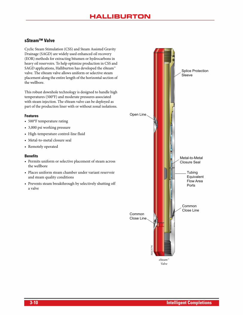
Open Line
Splice ProtectionSleeve
Metal-to-MetalClosure Seal
Tubing EquivalentFlow AreaPorts
CommonClose Line
CommonClose Line
HA
L31
791
sSteam™
Valve
3-10 Intelligent Completions
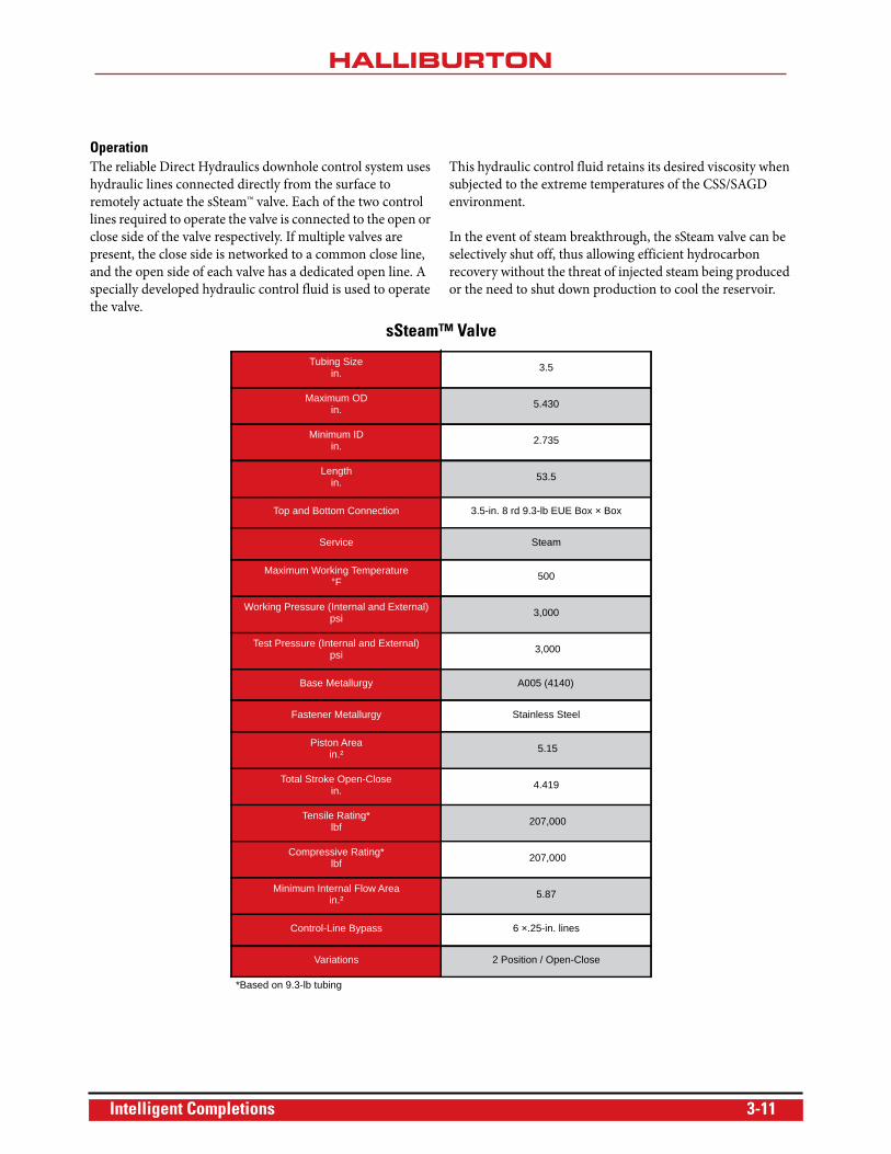
OperationThe reliable Direct Hydraulics downhole control system uses
hydraulic lines connected directly from the surface to
remotely actuate the sSteam™ valve. Each of the two control
lines required to operate the valve is connected to the open or
close side of the valve respectively. If multiple valves are
present, the close side is networked to a common close line,
and the open side of each valve has a dedicated open line. A
specially developed hydraulic control fluid is used to operate
the valve.
This hydraulic control fluid retains its desired viscosity when
subjected to the extreme temperatures of the CSS/SAGD
environment.
In the event of steam breakthrough, the sSteam valve can be
selectively shut off, thus allowing efficient hydrocarbon
recovery without the threat of injected steam being produced
or the need to shut down production to cool the reservoir.
sSteam™ Valve
Tubing Sizein. 3.5
Maximum ODin. 5.430
Minimum IDin. 2.735
Lengthin. 53.5
Top and Bottom Connection 3.5-in. 8 rd 9.3-lb EUE Box × Box
Service Steam
Maximum Working Temperature°F 500
Working Pressure (Internal and External)psi 3,000
Test Pressure (Internal and External)psi 3,000
Base Metallurgy A005 (4140)
Fastener Metallurgy Stainless Steel
Piston Areain.² 5.15
Total Stroke Open-Closein. 4.419
Tensile Rating*lbf 207,000
Compressive Rating*lbf 207,000
Minimum Internal Flow Areain.² 5.87
Control-Line Bypass 6 ×.25-in. lines
Variations 2 Position / Open-Close
*Based on 9.3-lb tubing
Intelligent Completions 3-11
Zonal Isolation Packers
HF-1 Packer
The HF-1 packer is a single-string, retrievable, cased-hole
packer that features a facility for bypass of multiple electrical
and/or hydraulic control lines. Available for use as both the
top production packer or as one of many lower packers
isolating adjacent zones, the HF-1 packer includes a
specialized slip configuration and additional body lock ring,
which allow it to operate under higher loads and greater
pressures than standard production packers.
Features• Hydraulically activated interlock mechanism prevents
premature setting
• No body movement during setting
• Premium thread connections
• NBR and HNBR element with anti-extrusion system
• Tailpipe can be left in tension or compression
Benefits• Less damage to casing using a multi-cone, full coverage
slip system
• Fully retrievable after installation
• Can be deployed with SmartWell® systems
• May be used as both top production packer and lower
isolation packer
• Avoid damage to control line during setting
Setting MechanismsThe HF-1 packer has two setting and three release
mechanisms.
• Setting Mechanisms
– Tubing pressure set
– Control-line set
• Release Mechanisms
– Punch and pressure release
– Shift and pressure release
– Mechanical shift release
The release mechanism is recessed and selective, allowing for
passage of other toolstrings. Axial loads are supported in both
directions so the tool cannot be released by tubing forces.
ConnectionsThe packer is made up directly to the tubing string via
integral premium thread connections. The internal mandrel
also uses premium thread connections for continuity.
• Anti-pre-set mechanisms – incorporates a hydraulically
activated interlock system and can be adjusted prior to
running in the hole. The interlock system allows the
packer to be run in highly deviated or horizontal wells,
eliminating the risk of pre-setting due to casing drag.
• Tandem setting – designed for tandem setting with
tailpipe in tension, compression, or neutral. Setting
mechanism is independent of tubing movement or
pressure induced tubing forces. Setting action will not
impart loads on or damage any penetrations or lines.
PenetrationsProvision is made for the passage of multiple hydraulic and/or
electrical control lines. All connections are sealed using
Halliburton proprietary FMJ connectors.
Elastomeric SealsMaterial for setting chamber seals and tubing to lower
annulus is chosen based on application conditions.
Integral Element Anti-Extrusion SystemThe packing element is multi-piece with NBR sealing
elements. It incorporates an anti-extrusion system that
provides high resistance to swab off, which permits increased
running speeds and high annular circulation rates (up to
8 bbl/min) prior to setting. The system has been qualified
through multiple thermal cycles using both water and
nitrogen as test media.
Load and Functional PerformanceAll HF-series packers are ISO-14310 V0 or V3 rated.
3-12 Intelligent Completions
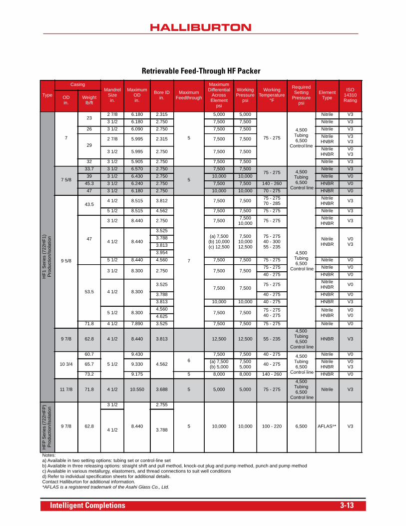
Retrievable Feed-Through HF Packer
Type
Casing Mandrel
Size in.
Maximum OD in.
Bore ID in.
Maximum Feedthrough
Maximum Differential
Across Element
psi
Working Pressure
psi
Working Temperature
°F
Required Setting
Pressure psi
Element Type
ISO 14310 RatingOD
in.Weight
lb/ft
HF1
Ser
ies
(722
HF1
) P
rodu
ctio
n/Is
olat
ion
7
232 7/8 6.180 2.315
5
5,000 5,000
75 - 275
4,500 Tubing 6,500
Control line
Nitrile V33 1/2 6.180 2.750 7,500 7,500 Nitrile V3
26 3 1/2 6.090 2.750 7,500 7,500 Nitrile V3
292 7/8 5.995 2.315 7,500 7,500 Nitrile
HNBRV3V3
3 1/2 5.995 2.750 7,500 7,500 Nitrile HNBR
V0V3
32 3 1/2 5.905 2.750 7,500 7,500 Nitrile V3
7 5/8
33.7 3 1/2 6.570 2.750
5
7,500 7,50075 - 275 4,500
Tubing 6,500
Control line
Nitrile V339 3 1/2 6.430 2.750 10,000 10,000 Nitrile V0
45.3 3 1/2 6.240 2.750 7,500 7,500 140 - 260 HNBR V047 3 1/2 6.180 2.750 10,000 10,000 70 - 275 HNBR V0
9 5/8
43.54 1/2 8.515 3.812
7
7,500 7,500 75 - 27570 - 285
4,500 Tubing 6,500
Control line
NitrileHNBR V3
5 1/2 8.515 4.562 7,500 7,500 75 - 275 Nitrile V3
47
3 1/2 8.440 2.750 7,500 7,500 10,000 75 - 275 Nitrile
HNBR V3
4 1/2 8.440
3.525(a) 7,500
(b) 10,000(c) 12,500
7,500 10,00012,500
75 - 27540 - 30055 - 235
Nitrile HNBR
V0V3
3.7883.8133.954
5 1/2 8.440 4.560 7,500 7,500 75 - 275 Nitrile V0
53.5
3 1/2 8.300 2.750 7,500 7,50075 - 275 Nitrile V040 - 275 HNBR V0
4 1/2 8.3003.525
7,500 7,50075 - 275 Nitrile
HNBR V0
3.788 40 - 275 HNBR V03.813 10,000 10,000 40 - 275 HNBR V3
5 1/2 8.3004.560
7,500 7,500 75 - 27540 - 275
Nitrile HNBR
V0V04.625
71.8 4 1/2 7.890 3.525 7,500 7,500 75 - 275 Nitrile V0
9 7/8 62.8 4 1/2 8.440 3.813 12,500 12,500 55 - 235
4,500 Tubing 6,500
Control line
HNBR V3
10 3/4
60.7
5 1/2
9.430
4.5626
7,500 7,500 40 - 275 4,500 Tubing 6,500
Control line
Nitrile V0
65.7 9.330 (a) 7,500(b) 5,000
7,500 5,000 40 - 275 Nitrile
HNBRV0V3
73.2 9.175 5 8,000 8,000 140 - 260 HNBR V0
11 7/8 71.8 4 1/2 10.550 3.688 5 5,000 5,000 75 - 275
4,500 Tubing 6,500
Control line
Nitrile V3
HFP
Ser
ies
(722
HFP
) P
rodu
ctio
n/Is
olat
ion
9 7/8 62.8
3 1/2
8.440
2.755
5 10,000 10,000 100 - 220 6,500 AFLAS®* V34 1/2 3.788
Notes:a) Available in two setting options: tubing set or control-line setb) Available in three releasing options: straight shift and pull method, knock-out plug and pump method, punch and pump methodc) Available in various metallurgy, elastomers, and thread connections to suit well conditionsd) Refer to individual specification sheets for additional details.Contact Halliburton for additional information.*AFLAS is a registered trademark of the Asahi Glass Co., Ltd.
Intelligent Completions 3-13
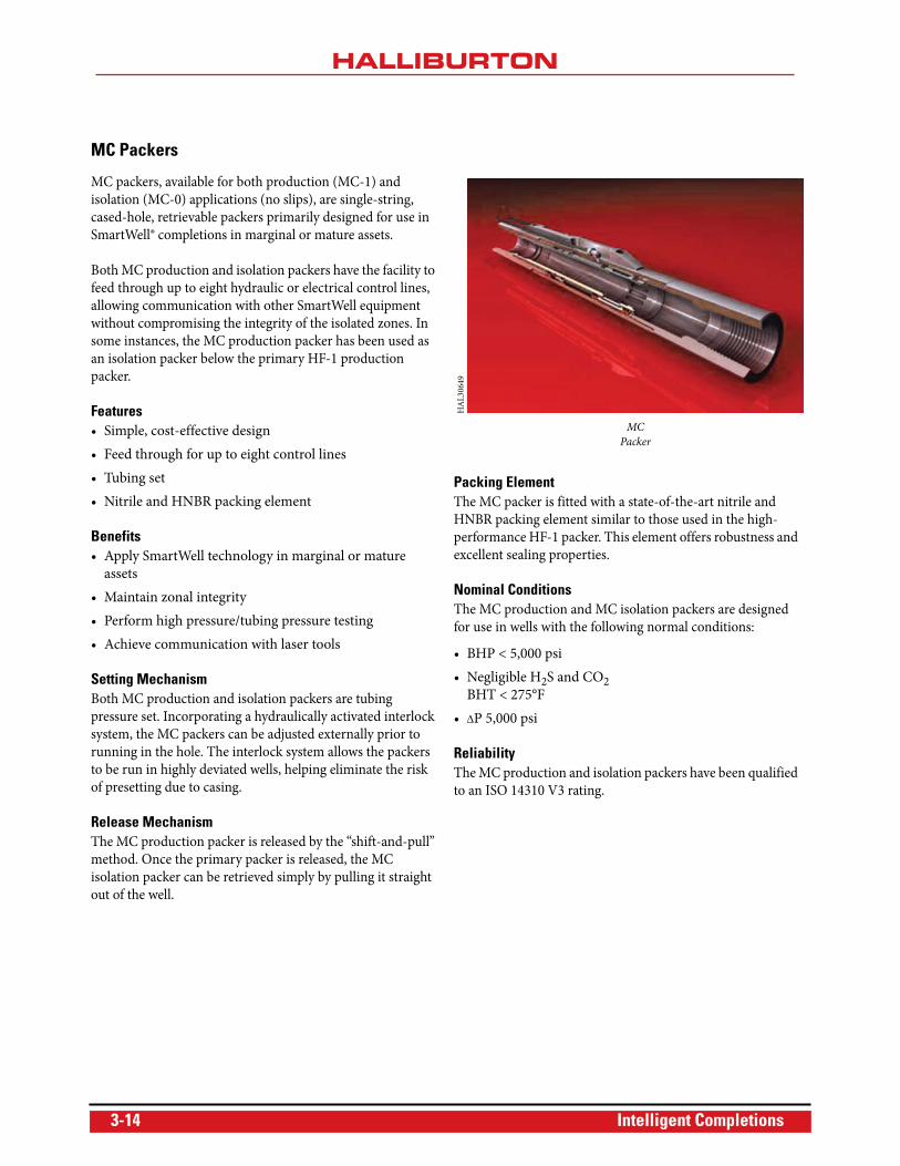
MC Packers
MC packers, available for both production (MC-1) and
isolation (MC-0) applications (no slips), are single-string,
cased-hole, retrievable packers primarily designed for use in
SmartWell® completions in marginal or mature assets.
Both MC production and isolation packers have the facility to
feed through up to eight hydraulic or electrical control lines,
allowing communication with other SmartWell equipment
without compromising the integrity of the isolated zones. In
some instances, the MC production packer has been used as
an isolation packer below the primary HF-1 production
packer.
Features• Simple, cost-effective design
• Feed through for up to eight control lines
• Tubing set
• Nitrile and HNBR packing element
Benefits• Apply SmartWell technology in marginal or mature
assets
• Maintain zonal integrity
• Perform high pressure/tubing pressure testing
• Achieve communication with laser tools
Setting MechanismBoth MC production and isolation packers are tubing
pressure set. Incorporating a hydraulically activated interlock
system, the MC packers can be adjusted externally prior to
running in the hole. The interlock system allows the packers
to be run in highly deviated wells, helping eliminate the risk
of presetting due to casing.
Release MechanismThe MC production packer is released by the “shift-and-pull”
method. Once the primary packer is released, the MC
isolation packer can be retrieved simply by pulling it straight
out of the well.
Packing ElementThe MC packer is fitted with a state-of-the-art nitrile and
HNBR packing element similar to those used in the high-
performance HF-1 packer. This element offers robustness and
excellent sealing properties.
Nominal ConditionsThe MC production and MC isolation packers are designed
for use in wells with the following normal conditions:
• BHP < 5,000 psi
• Negligible H2S and CO2BHT < 275°F
• P 5,000 psi
ReliabilityThe MC production and isolation packers have been qualified
to an ISO 14310 V3 rating.
MC
Packer
HA
L30
649
3-14 Intelligent Completions
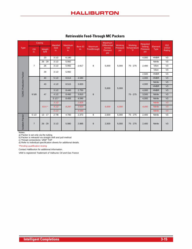
Retrievable Feed-Through MC Packers
Type
Casing Mandrel
Size in.
Maximum OD in.
Bore ID in.
Maximum Feedthrough
Maximum Differential
Across Element
psi
Working Pressure
psi
Working Temperature
°F
Required Setting
Pressure psi
Element Type
ISO 14310 RatingOD
in.Weight
lb/ft
722M
C P
rodu
ctio
n P
acke
r
7
23 3 1/2 6.180
2.817 8 5,000 5,000 75 - 275
4,000 HNBR V3
26 - 29 3 1/2 5.992
2,400
Nitrile V3
26 3 1/2 5.992 Viton V3
29 3 1/2 5.992Viton V3
2,500 HNBR V3
9 5/8
40 5 1/2 8.614 4.580
8
5,000 5,000
75 - 275
4,000 HNBR V3
43 4 1/2 8.515 3.820 4,000Nitrile V3
HNBR V3
47
3 1/2 8.440 2.750 4,000 HNBR V3
4 1/2 8.460 3.810 3,500 Nitrile V3
5 1/2 * 8.455 4.590 4,000 Nitrile V3
53.5 *
3 1/2
8.297
2.825
5,000 5,000 4,000
Nitrile V3
4 1/2 3.820 Nitrile V3
5 1/2 4.590 Nitrile V3
Isol
atio
n P
acke
r 5 1/2 13 - 17 2 7/8 4.700 2.373 8 2,500 5,000 75 - 275 2,400 Nitrile V3
7 26 - 29 3 1/2 5.980 2.885 8 2,500 5,000 75 - 275 2,400 Nitrile V3
Notes:a) Packer is set only via the tubing.b) Packer is released via straight shift and pull methodc) Thread connections: VAM® TOPd) Refer to individual specification sheets for additional details.*Pending qualification testingContact Halliburton for additional information.VAM is registered Trademark of Vallourec Oil and Gas France
Intelligent Completions 3-15
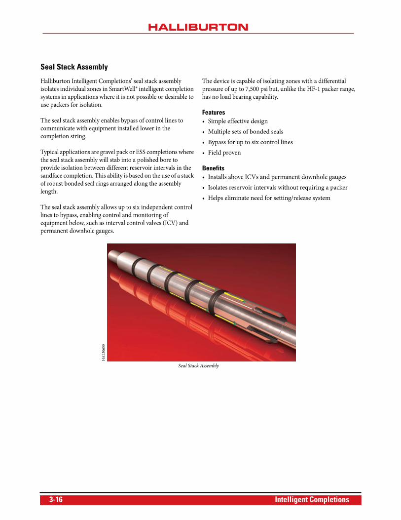
Seal Stack Assembly
Halliburton Intelligent Completions’ seal stack assembly
isolates individual zones in SmartWell® intelligent completion
systems in applications where it is not possible or desirable to
use packers for isolation.
The seal stack assembly enables bypass of control lines to
communicate with equipment installed lower in the
completion string.
Typical applications are gravel pack or ESS completions where
the seal stack assembly will stab into a polished bore to
provide isolation between different reservoir intervals in the
sandface completion. This ability is based on the use of a stack
of robust bonded seal rings arranged along the assembly
length.
The seal stack assembly allows up to six independent control
lines to bypass, enabling control and monitoring of
equipment below, such as interval control valves (ICV) and
permanent downhole gauges.
The device is capable of isolating zones with a differential
pressure of up to 7,500 psi but, unlike the HF-1 packer range,
has no load bearing capability.
Features• Simple effective design
• Multiple sets of bonded seals
• Bypass for up to six control lines
• Field proven
Benefits• Installs above ICVs and permanent downhole gauges
• Isolates reservoir intervals without requiring a packer
• Helps eliminate need for setting/release system
Seal Stack Assembly
HA
L30
650
3-16 Intelligent Completions
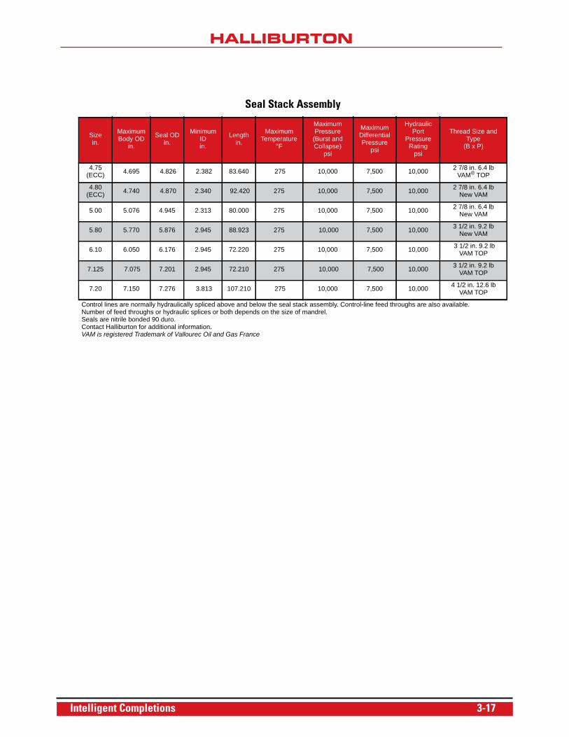
Seal Stack Assembly
Size in.
Maximum Body OD
in.
Seal OD in.
Minimum IDin.
Length in.
MaximumTemperature
°F
MaximumPressure
(Burst and Collapse)
psi
MaximumDifferential Pressure
psi
Hydraulic Port
Pressure Rating
psi
Thread Size and Type
(B x P)
4.75 (ECC) 4.695 4.826 2.382 83.640 275 10,000 7,500 10,000 2 7/8 in. 6.4 lb
VAM® TOP
4.80 (ECC) 4.740 4.870 2.340 92.420 275 10,000 7,500 10,000 2 7/8 in. 6.4 lb
New VAM
5.00 5.076 4.945 2.313 80.000 275 10,000 7,500 10,000 2 7/8 in. 6.4 lb New VAM
5.80 5.770 5.876 2.945 88.923 275 10,000 7,500 10,000 3 1/2 in. 9.2 lb New VAM
6.10 6.050 6.176 2.945 72.220 275 10,000 7,500 10,000 3 1/2 in. 9.2 lb VAM TOP
7.125 7.075 7.201 2.945 72.210 275 10,000 7,500 10,000 3 1/2 in. 9.2 lb VAM TOP
7.20 7.150 7.276 3.813 107.210 275 10,000 7,500 10,000 4 1/2 in. 12.6 lb VAM TOP
Control lines are normally hydraulically spliced above and below the seal stack assembly. Control-line feed throughs are also available.Number of feed throughs or hydraulic splices or both depends on the size of mandrel.Seals are nitrile bonded 90 duro.Contact Halliburton for additional information.VAM is registered Trademark of Vallourec Oil and Gas France
Intelligent Completions 3-17
Downhole Control Systems
Downhole control systems provide a method of integrating
the surface control system (either manual or automated) with
downhole SmartWell® equipment.
SCRAMS® Surface Controlled ReservoirAnalysis and Management System
The SCRAMS® system is a fully integrated control and data
acquisition system that allows the operator to remotely control
the wellbore and obtain real-time pressure/temperature data
for each zone. This data feedback and accurate flow control
capability allow the operator to optimize reservoir
performance and enhance reservoir management.
The SCRAMS system is ideal for onshore, platform, and subsea
applications and is typically used to control the HS-ICV valve
for precise control of flow into or out of a reservoir interval.
Features• Can be used to control infinitely variable hydraulic flow
control valves
• Can be used for land, platform, or subsea applications
• Capable of interfacing with multiple subsea control
vendors
• Infinitely variable control valve positioning
• Flow estimation derived from fundamental metrology
Benefits• Optimize reservoir performance by controlling multiple
reservoirs without intervention
• Enhance reservoir management through real-time data
acquisition
• Remotely control the wellbore
• Obtain real-time pressure/temperature data for each
reservoir interval
• Steer around faults for continued functionality using full
redundancy capability
• Control multiple intervals from only one of the two
electro-hydraulic flatpacks through multi-drop
functionality
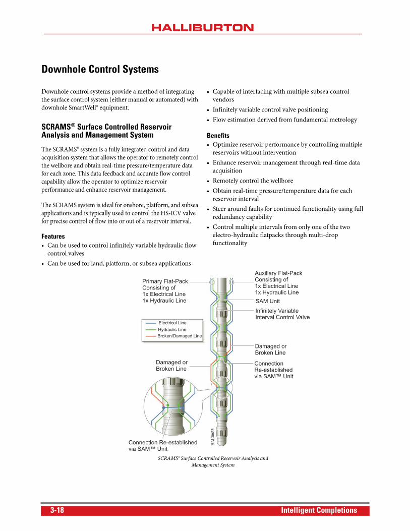
Primary Flat-PackConsisting of1x Electrical Line1x Hydraulic Line
Electrical Line
Hydraulic Line
Broken/Damaged Line
Damaged orBroken Line
Connection Re-establishedvia SAM™ Unit
ConnectionRe-establishedvia SAM™ Unit
Damaged orBroken Line
Infinitely VariableInterval Control Valve
SAM Unit
Auxiliary Flat-PackConsisting of1x Electrical Line1x Hydraulic Line
SCRAMS® Surface Controlled Reservoir Analysis and
Management System
HA
L30
655
3-18 Intelligent Completions
OperationThe link from the control equipment located outside the well
to the downhole tools includes redundant hydraulic and
electrical buses in the form of control lines and electrical
conductors enclosed in a flatpack. The hydraulic control line
provides the hydraulic locomotive force to the SAM™ sensor-
actuated module tool, which in turn, using solenoid valves,
distributes this force to each side of the ICV piston. The
electrical conductor allows transmission of power and
communication signals from the well controller to all of the
downhole tools by means of the multi-drop telemetry system.
To simplify and increase the reliability of the cable to the
downhole tool interface, the SCRAMS® system adopts a
signal-on power telemetry system. To further enhance the
downhole system survivability, the redundant electric and
hydraulic network is segmented (SegNet™communications
protocol). If any failure, either electric or hydraulic, develops
in any section of the network between surface and the
downhole tools, the SegNet communications protocol
provides the ability to steer around the failure, retaining full
functionality of the complete SmartWell® completion system.
SAM™ Sensor Actuation ModuleThe SAM™ tool provides the control and data acquisition
functionality for the SCRAMS system. The SAM tool
contains redundant electronics, each separately connected to
individual flatpacks, a hydraulic manifold to distribute
hydraulic power, and sensors for pressure/temperature
measurement. The SAM tool is the active component of the
SegNet infrastructure. Incoming electrical and hydraulic
buses are terminated into the SAM tool and exit to provide
communication to other SAM tools further down the
completion string. Solenoid valve and electrical switches
incorporated in the SAM tool allow isolation of any
potentially faulty sections of the network connecting the next
tool in the completion.
Intelligent Completions 3-19
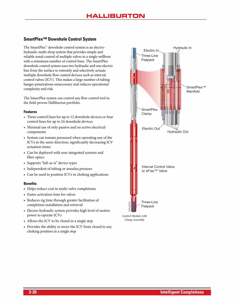
SmartPlex™ Downhole Control System
The SmartPlex™ downhole control system is an electro-
hydraulic multi-drop system that provides simple and
reliable zonal control of multiple valves in a single wellbore
with a minimum number of control lines. The SmartPlex
downhole control system uses two hydraulic and one electric
line from the surface to remotely and selectively actuate
multiple downhole flow control devices such as interval
control valves (ICV). This makes a large number of tubing
hanger penetrations unnecessary and reduces operational
complexity and risk.
The SmartPlex system can control any flow control tool in
the field-proven Halliburton portfolio.
Features• Three control lines for up to 12 downhole devices or four
control lines for up to 24 downhole devices
• Minimal use of only passive and no active electrical
components
• System can remain pressured when operating any of the
ICVs in the same direction, significantly decreasing ICV
actuation times
• Can be deployed with non-integrated systems and
fiber optics
• Supports “fail-as-is” device types
• Independent of tubing or annulus pressure
• Can be used to position ICVs in choking applications
Benefits• Helps reduce cost in multi-valve completions
• Faster activation time for valves
• Reduces rig time through greater facilitation of
completion installation and retrieval
• Electro-hydraulic system provides high level of motive
power to operate ICVs
• Allows the ICV to be closed in a single step
• Provides the ability to move the ICV from closed to any
choking position in a single step
Three-LineFlatpack
Electric InHydraulic In
SmartPlex™Manifold
SmartPlexClamp
Electric OutHydraulic Out
Interval Control Valveor sFrac™ Valve
Three-LineFlatpack
Control Module with
Clamp Assembly
HA
L32
214
3-20 Intelligent Completions
ApplicationThe SmartPlex™ downhole control system is applicable for
any dry tree multi-zone completion requiring more than two
valves. When compared to the Direct Hydraulics system, the
SmartPlex system not only helps reduce the overall cost of an
intelligent completion, but also reduces the complexity
involved by minimizing the number of control lines required.
The SmartPlex system is ideally suited for long horizontal,
compartmentalized completions, in both cased or open hole,
where selective control of each interval is desired. Typically
this can be advantageous for selective stimulation control in
tight gas applications or in combination with a choking ICV
for drawdown optimization in production applications.
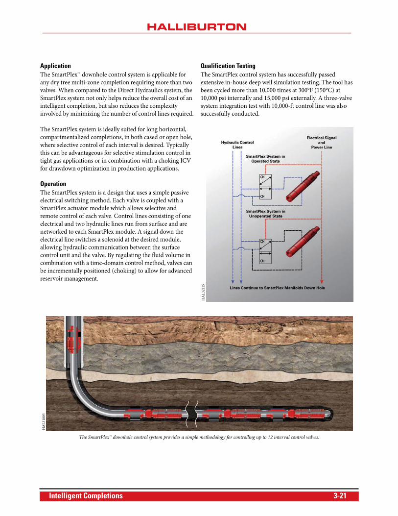
OperationThe SmartPlex system is a design that uses a simple passive
electrical switching method. Each valve is coupled with a
SmartPlex actuator module which allows selective and
remote control of each valve. Control lines consisting of one
electrical and two hydraulic lines run from surface and are
networked to each SmartPlex module. A signal down the
electrical line switches a solenoid at the desired module,
allowing hydraulic communication between the surface
control unit and the valve. By regulating the fluid volume in
combination with a time-domain control method, valves can
be incrementally positioned (choking) to allow for advanced
reservoir management.
Qualification TestingThe SmartPlex control system has successfully passed
extensive in-house deep well simulation testing. The tool has
been cycled more than 10,000 times at 300°F (150°C) at
10,000 psi internally and 15,000 psi externally. A three-valve
system integration test with 10,000-ft control line was also
successfully conducted.
HA
L32
215
The SmartPlex™ downhole control system provides a simple methodology for controlling up to 12 interval control valves.
HA
L31
805
Intelligent Completions 3-21
Digital Hydraulics™ Downhole Control System
The Digital Hydraulics™ system is an all-hydraulic, multi-
drop intelligent completion system that can direct any flow
control tool in the Halliburton portfolio, providing simple
and reliable zonal control for even the most complex
reservoirs. The Digital Hydraulics system allows up to six
flow control devices to be controlled from only three
hydraulic control lines, making a large number of tubing
hanger penetrations unnecessary.
Features• High activation forces for flow control devices in
both directions
• Three control lines for up to six downhole devices
• Four control lines for up to 12 downhole valves
• Can be deployed with non-integrated systems and
fiber optics
• No setting depth limitations
• All-hydraulic system
• Supports “fail as is” devices
• Field-proven
• Independent of tubing or annular pressure
Benefits• Helps reduce control line costs
• Helps reduce rig time through greater facilitation of
completion installation and retrieval
• Fewer connections through tubing hanger
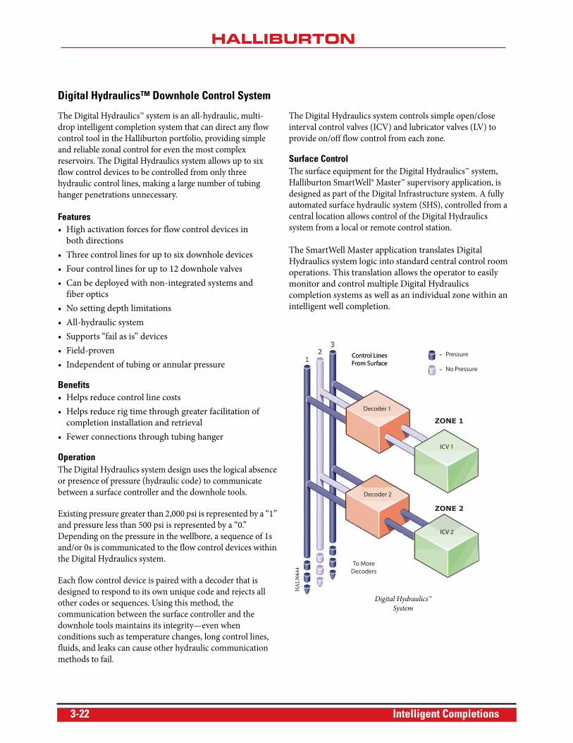
OperationThe Digital Hydraulics system design uses the logical absence
or presence of pressure (hydraulic code) to communicate
between a surface controller and the downhole tools.
Existing pressure greater than 2,000 psi is represented by a “1”
and pressure less than 500 psi is represented by a “0.”
Depending on the pressure in the wellbore, a sequence of 1s
and/or 0s is communicated to the flow control devices within
the Digital Hydraulics system.
Each flow control device is paired with a decoder that is
designed to respond to its own unique code and rejects all
other codes or sequences. Using this method, the
communication between the surface controller and the
downhole tools maintains its integrity—even when
conditions such as temperature changes, long control lines,
fluids, and leaks can cause other hydraulic communication
methods to fail.
The Digital Hydraulics system controls simple open/close
interval control valves (ICV) and lubricator valves (LV) to
provide on/off flow control from each zone.
Surface ControlThe surface equipment for the Digital Hydraulics™ system,
Halliburton SmartWell® Master™ supervisory application, is
designed as part of the Digital Infrastructure system. A fully
automated surface hydraulic system (SHS), controlled from a
central location allows control of the Digital Hydraulics
system from a local or remote control station.
The SmartWell Master application translates Digital
Hydraulics system logic into standard central control room
operations. This translation allows the operator to easily
monitor and control multiple Digital Hydraulics
completion systems as well as an individual zone within an
intelligent well completion.
Control LinesFrom SurfaceControl LinesFrom Surface
To More Decoders
Pressure
Decoder 1
Decoder 2
ICV 1
ICV 2
No Pressure
Digital Hydraulics™
System
HA
L30
644
3-22 Intelligent Completions
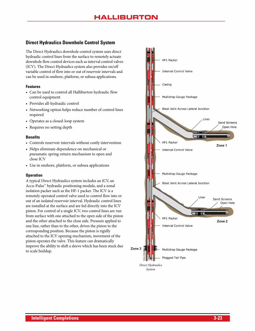
Direct Hydraulics Downhole Control System
The Direct Hydraulics downhole control system uses direct
hydraulic control lines from the surface to remotely actuate
downhole flow control devices such as interval control valves
(ICV). The Direct Hydraulics system also provides on/off
variable control of flow into or out of reservoir intervals and
can be used in onshore, platform, or subsea applications.
Features• Can be used to control all Halliburton hydraulic flow
control equipment
• Provides all-hydraulic control
• Networking option helps reduce number of control lines
required
• Operates as a closed-loop system
• Requires no setting depth
Benefits• Controls reservoir intervals without costly intervention
• Helps eliminate dependence on mechanical or
pneumatic spring-return mechanism to open and
close ICV
• Use in onshore, platform, or subsea applications
OperationA typical Direct Hydraulics system includes an ICV, an
Accu-Pulse™ hydraulic positioning module, and a zonal
isolation packer such as the HF-1 packer. The ICV is a
remotely operated control valve used to control flow into or
out of an isolated reservoir interval. Hydraulic control lines
are installed at the surface and are fed directly into the ICV
piston. For control of a single ICV, two control lines are run
from surface with one attached to the open side of the piston
and the other attached to the close side. Pressure applied to
one line, rather than to the other, drives the piston to the
corresponding position. Because the piston is rigidly
attached to the ICV opening mechanism, movement of the
piston operates the valve. This feature can dramatically
improve the ability to shift a sleeve which has been stuck due
to scale buildup.
HA
L30
640
Direct Hydraulics
System
Intelligent Completions 3-23
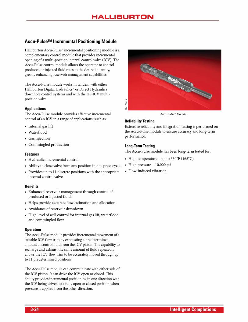
Accu-Pulse™ Incremental Positioning Module
Halliburton Accu-Pulse™ incremental positioning module is a
complementary control module that provides incremental
opening of a multi-position interval control valve (ICV). The
Accu-Pulse control module allows the operator to control
produced or injected fluid rates to the desired quantity,
greatly enhancing reservoir management capabilities.
The Accu-Pulse module works in tandem with either
Halliburton Digital Hydraulics™ or Direct Hydraulics
downhole control systems and with the HS-ICV multi-
position valve.
ApplicationsThe Accu-Pulse module provides effective incremental
control of an ICV in a range of applications, such as:
• Internal gas lift
• Waterflood
• Gas injection
• Commingled production
Features• Hydraulic, incremental control
• Ability to close valve from any position in one press cycle
• Provides up to 11 discrete positions with the appropriate
interval control valve
Benefits• Enhanced reservoir management through control of
produced or injected fluids
• Helps provide accurate flow estimation and allocation
• Avoidance of reservoir drawdown
• High level of well control for internal gas lift, waterflood,
and commingled flow
OperationThe Accu-Pulse module provides incremental movement of a
suitable ICV flow trim by exhausting a predetermined
amount of control fluid from the ICV piston. The capability to
recharge and exhaust the same amount of fluid repeatedly
allows the ICV flow trim to be accurately moved through up
to 11 predetermined positions.
The Accu-Pulse module can communicate with either side of
the ICV piston. It can drive the ICV open or closed. This
ability provides incremental positioning in one direction with
the ICV being driven to a fully open or closed position when
pressure is applied from the other direction.
Reliability TestingExtensive reliability and integration testing is performed on
the Accu-Pulse module to ensure accuracy and long-term
performance.
Long-Term TestingThe Accu-Pulse module has been long-term tested for:
• High temperature – up to 330°F (165°C)
• High pressure – 10,000 psi
• Flow-induced vibration
Accu-Pulse™ Module
HA
L30
629
3-24 Intelligent Completions
Auxiliary Components
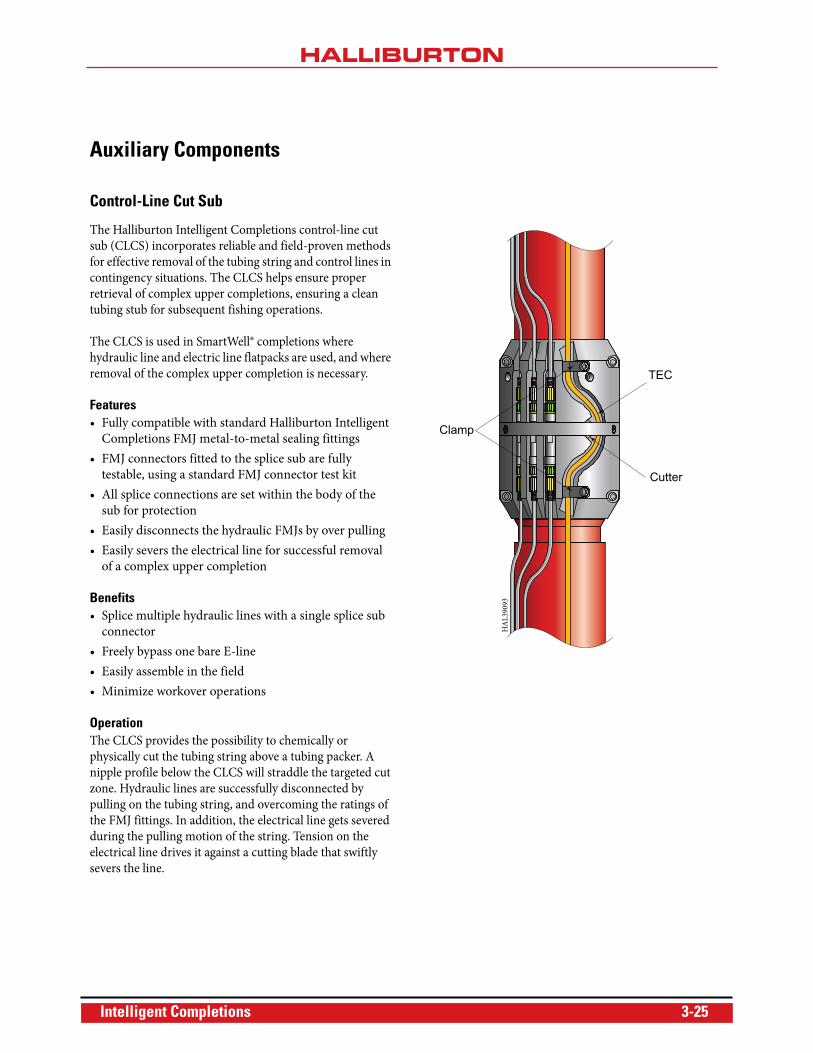
Control-Line Cut Sub
The Halliburton Intelligent Completions control-line cut
sub (CLCS) incorporates reliable and field-proven methods
for effective removal of the tubing string and control lines in
contingency situations. The CLCS helps ensure proper
retrieval of complex upper completions, ensuring a clean
tubing stub for subsequent fishing operations.
The CLCS is used in SmartWell® completions where
hydraulic line and electric line flatpacks are used, and where
removal of the complex upper completion is necessary.
Features• Fully compatible with standard Halliburton Intelligent
Completions FMJ metal-to-metal sealing fittings
• FMJ connectors fitted to the splice sub are fully
testable, using a standard FMJ connector test kit
• All splice connections are set within the body of the
sub for protection
• Easily disconnects the hydraulic FMJs by over pulling
• Easily severs the electrical line for successful removal
of a complex upper completion
Benefits• Splice multiple hydraulic lines with a single splice sub
connector
• Freely bypass one bare E-line
• Easily assemble in the field
• Minimize workover operations
OperationThe CLCS provides the possibility to chemically or
physically cut the tubing string above a tubing packer. A
nipple profile below the CLCS will straddle the targeted cut
zone. Hydraulic lines are successfully disconnected by
pulling on the tubing string, and overcoming the ratings of
the FMJ fittings. In addition, the electrical line gets severed
during the pulling motion of the string. Tension on the
electrical line drives it against a cutting blade that swiftly
severs the line.
Clamp
TEC
Cutter
HA
L39
093
Intelligent Completions 3-25
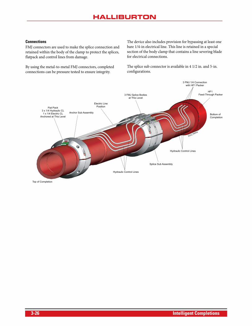
ConnectionsFMJ connectors are used to make the splice connection and
retained within the body of the clamp to protect the splices,
flatpack and control lines from damage.
By using the metal-to-metal FMJ connectors, completed
connections can be pressure tested to ensure integrity.
The device also includes provision for bypassing at least one
bare 1/4-in electrical line. This line is retained in a special
section of the body clamp that contains a line severing blade
for electrical connections.
The splice sub connector is available in 4 1/2 in. and 5-in.
configurations.
Electric LinePosition
Anchor Sub Assembly
3 FMJ Splice Bodiesat This Level
Splice Sub Assembly
Hydraulic Control Lines
Hydraulic Control Lines
3 FMJ 1/4 Connectionwith HF1 Packer
Bottom ofCompletion
Top of Completion
HF1 Feed-Through Packer
Flat Pack3 x 1/4 Hydraulic CL1 x 1/4 Electric CL
Anchored at This Level
HAL39094
3-26 Intelligent Completions
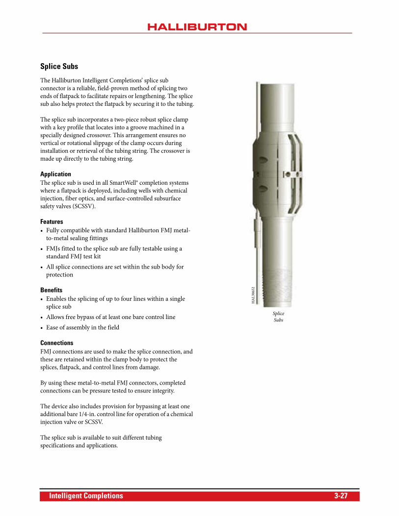
Splice Subs
The Halliburton Intelligent Completions’ splice sub
connector is a reliable, field-proven method of splicing two
ends of flatpack to facilitate repairs or lengthening. The splice
sub also helps protect the flatpack by securing it to the tubing.
The splice sub incorporates a two-piece robust splice clamp
with a key profile that locates into a groove machined in a
specially designed crossover. This arrangement ensures no
vertical or rotational slippage of the clamp occurs during
installation or retrieval of the tubing string. The crossover is
made up directly to the tubing string.
ApplicationThe splice sub is used in all SmartWell® completion systems
where a flatpack is deployed, including wells with chemical
injection, fiber optics, and surface-controlled subsurface
safety valves (SCSSV).
Features• Fully compatible with standard Halliburton FMJ metal-
to-metal sealing fittings
• FMJs fitted to the splice sub are fully testable using a
standard FMJ test kit
• All splice connections are set within the sub body for
protection
Benefits• Enables the splicing of up to four lines within a single
splice sub
• Allows free bypass of at least one bare control line
• Ease of assembly in the field
ConnectionsFMJ connections are used to make the splice connection, and
these are retained within the clamp body to protect the
splices, flatpack, and control lines from damage.
By using these metal-to-metal FMJ connectors, completed
connections can be pressure tested to ensure integrity.
The device also includes provision for bypassing at least one
additional bare 1/4-in. control line for operation of a chemical
injection valve or SCSSV.
The splice sub is available to suit different tubing
specifications and applications.
Splice
Subs
HA
L30
652
Intelligent Completions 3-27
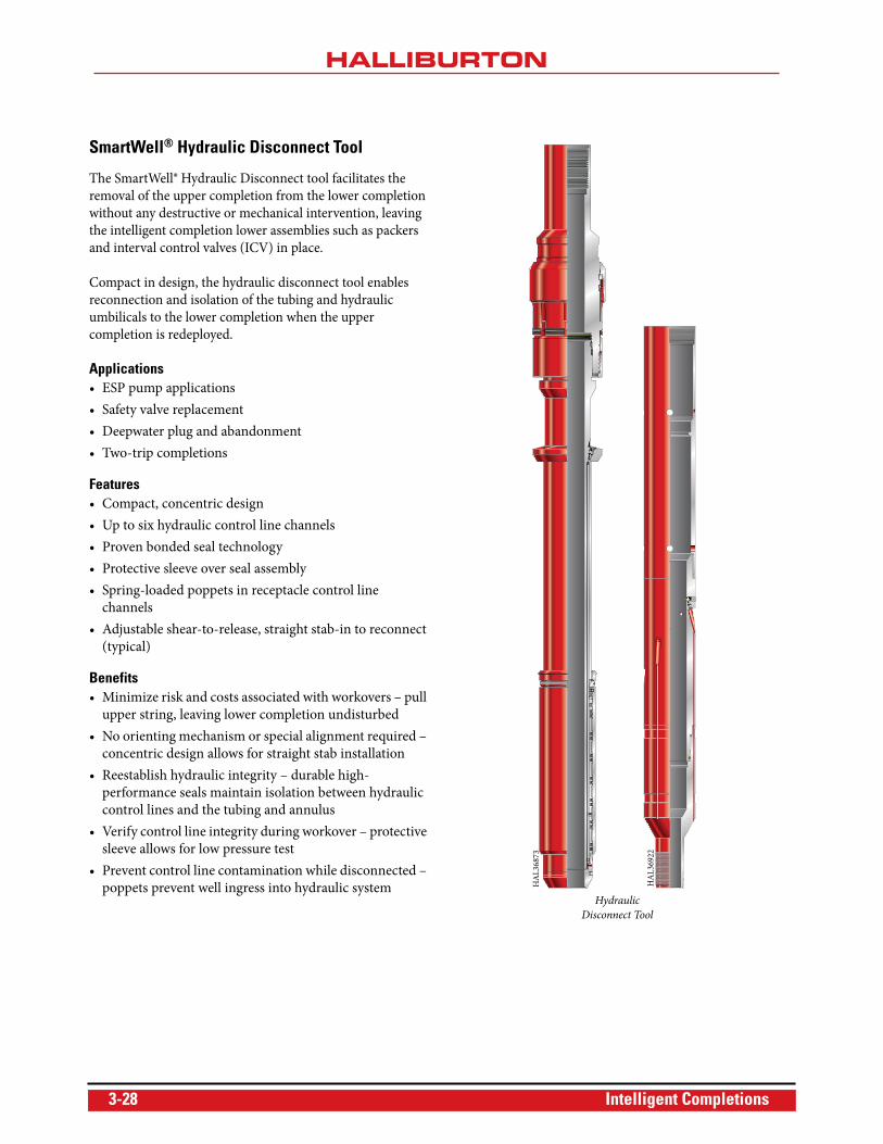
SmartWell® Hydraulic Disconnect Tool
The SmartWell® Hydraulic Disconnect tool facilitates the
removal of the upper completion from the lower completion
without any destructive or mechanical intervention, leaving
the intelligent completion lower assemblies such as packers
and interval control valves (ICV) in place.
Compact in design, the hydraulic disconnect tool enables
reconnection and isolation of the tubing and hydraulic
umbilicals to the lower completion when the upper
completion is redeployed.
Applications• ESP pump applications
• Safety valve replacement
• Deepwater plug and abandonment
• Two-trip completions
Features• Compact, concentric design
• Up to six hydraulic control line channels
• Proven bonded seal technology
• Protective sleeve over seal assembly
• Spring-loaded poppets in receptacle control line
channels
• Adjustable shear-to-release, straight stab-in to reconnect
(typical)
Benefits• Minimize risk and costs associated with workovers – pull
upper string, leaving lower completion undisturbed
• No orienting mechanism or special alignment required –
concentric design allows for straight stab installation
• Reestablish hydraulic integrity – durable high-
performance seals maintain isolation between hydraulic
control lines and the tubing and annulus
• Verify control line integrity during workover – protective
sleeve allows for low pressure test
• Prevent control line contamination while disconnected –
poppets prevent well ingress into hydraulic systemHydraulic
Disconnect Tool
HA
L36
922
HA
L36
873
3-28 Intelligent Completions
OperationThe Hydraulic Disconnect tool features six hydraulic control
line channels that provide communication in a SmartWell®
completion.
All six channels are independent of each other, using
concentric seal channels that eliminate the need for special
orientation.
While running the upper assembly, a protective sleeve covers
the seals, preventing damage and providing a means to verify
hydraulic control line integrity. The sleeve is engaged during
stab-in, sliding up the seal assembly to safely present the seals
in the receptacle.
While disconnected, spring-loaded poppets provide a debris
barrier for the control line channels. The poppets are lifted
off seat by the seal mandrel during stab-in, establishing
hydraulic communication from the surface.
The secure latching mechanism can be configured on
location to complement the customer well plan. Three modes
of operation are available:
• Snap Latch: Snap In/Snap Out
• Anchor: Snap In/Rotate Out to Release
• Shear Anchor: Snap In/Shear to Release
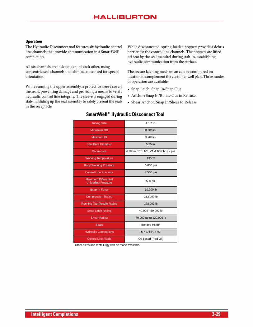
SmartWell® Hydraulic Disconnect Tool
Tubing Size 4 1/2 in.
Maximum OD 8.300 in.
Minimum ID 3.788 in.
Seal Bore Diameter 5.35 in.
Connection 4 1/2-in, 15.1 lb/ft, VAM TOP box × pin
Working Temperature 135°C
Body Working Pressure 5,000 psi
Control Line Pressure 7,500 psi
Maximum Differential Unloading Pressure 500 psi
Snap-In Force 10,000 lb
Compression Rating 353,000 lb
Running Tool Tensile Rating 178,000 lb
Snap Latch Rating 40,000 - 50,000 lb
Shear Rating 70,000 up to 120,000 lb
Seals Bonded HNBR
Hydraulic Connections 6 × 1/4-in. FMJ
Control Line Fluids Oil-based (Red Oil)
Other sizes and metallurgy can be made available.
Intelligent Completions 3-29
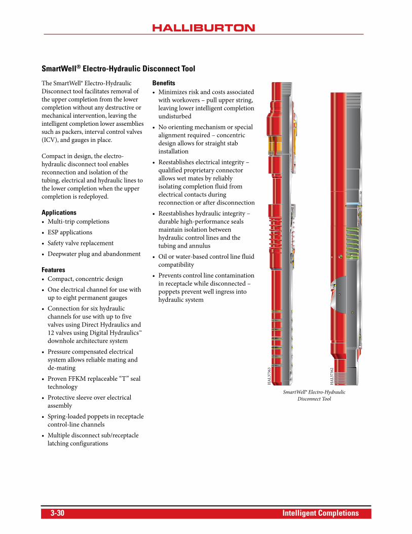
SmartWell® Electro-Hydraulic Disconnect Tool
The SmartWell® Electro-Hydraulic
Disconnect tool facilitates removal of
the upper completion from the lower
completion without any destructive or
mechanical intervention, leaving the
intelligent completion lower assemblies
such as packers, interval control valves
(ICV), and gauges in place.
Compact in design, the electro-
hydraulic disconnect tool enables
reconnection and isolation of the
tubing, electrical and hydraulic lines to
the lower completion when the upper
completion is redeployed.
Applications• Multi-trip completions
• ESP applications
• Safety valve replacement
• Deepwater plug and abandonment
Features• Compact, concentric design
• One electrical channel for use with
up to eight permanent gauges
• Connection for six hydraulic
channels for use with up to five
valves using Direct Hydraulics and
12 valves using Digital Hydraulics™
downhole architecture system
• Pressure compensated electrical
system allows reliable mating and
de-mating
• Proven FFKM replaceable “T” seal
technology
• Protective sleeve over electrical
assembly
• Spring-loaded poppets in receptacle
control-line channels
• Multiple disconnect sub/receptacle
latching configurations
Benefits• Minimizes risk and costs associated
with workovers – pull upper string,
leaving lower intelligent completion
undisturbed
• No orienting mechanism or special
alignment required – concentric
design allows for straight stab
installation
• Reestablishes electrical integrity –
qualified proprietary connector
allows wet mates by reliably
isolating completion fluid from
electrical contacts during
reconnection or after disconnection
• Reestablishes hydraulic integrity –
durable high-performance seals
maintain isolation between
hydraulic control lines and the
tubing and annulus
• Oil or water-based control line fluid
compatibility
• Prevents control line contamination
in receptacle while disconnected –
poppets prevent well ingress into
hydraulic system
SmartWell® Electro-Hydraulic
Disconnect Tool
HA
L37
362
HA
L37
363
3-30 Intelligent Completions
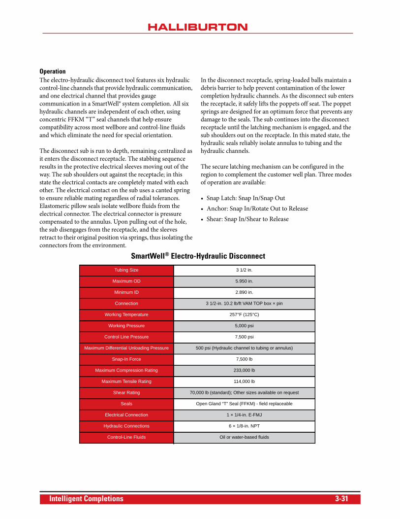
OperationThe electro-hydraulic disconnect tool features six hydraulic
control-line channels that provide hydraulic communication,
and one electrical channel that provides gauge
communication in a SmartWell® system completion. All six
hydraulic channels are independent of each other, using
concentric FFKM “T” seal channels that help ensure
compatibility across most wellbore and control-line fluids
and which eliminate the need for special orientation.
The disconnect sub is run to depth, remaining centralized as
it enters the disconnect receptacle. The stabbing sequence
results in the protective electrical sleeves moving out of the
way. The sub shoulders out against the receptacle; in this
state the electrical contacts are completely mated with each
other. The electrical contact on the sub uses a canted spring
to ensure reliable mating regardless of radial tolerances.
Elastomeric pillow seals isolate wellbore fluids from the
electrical connector. The electrical connector is pressure
compensated to the annulus. Upon pulling out of the hole,
the sub disengages from the receptacle, and the sleeves
retract to their original position via springs, thus isolating the
connectors from the environment.
In the disconnect receptacle, spring-loaded balls maintain a
debris barrier to help prevent contamination of the lower
completion hydraulic channels. As the disconnect sub enters
the receptacle, it safely lifts the poppets off seat. The poppet
springs are designed for an optimum force that prevents any
damage to the seals. The sub continues into the disconnect
receptacle until the latching mechanism is engaged, and the
sub shoulders out on the receptacle. In this mated state, the
hydraulic seals reliably isolate annulus to tubing and the
hydraulic channels.
The secure latching mechanism can be configured in the
region to complement the customer well plan. Three modes
of operation are available:
• Snap Latch: Snap In/Snap Out
• Anchor: Snap In/Rotate Out to Release
• Shear: Snap In/Shear to Release
SmartWell® Electro-Hydraulic Disconnect
Tubing Size 3 1/2 in.
Maximum OD 5.950 in.
Minimum ID 2.890 in.
Connection 3 1/2-in. 10.2 lb/ft VAM TOP box × pin
Working Temperature 257°F (125°C)
Working Pressure 5,000 psi
Control Line Pressure 7,500 psi
Maximum Differential Unloading Pressure 500 psi (Hydraulic channel to tubing or annulus)
Snap-In Force 7,500 lb
Maximum Compression Rating 233,000 lb
Maximum Tensile Rating 114,000 lb
Shear Rating 70,000 lb (standard); Other sizes available on request
Seals Open Gland “T” Seal (FFKM) - field replaceable
Electrical Connection 1 × 1/4-in. E-FMJ
Hydraulic Connections 6 × 1/8-in. NPT
Control-Line Fluids Oil or water-based fluids
Intelligent Completions 3-31
Permanent Monitoring
Halliburton Intelligent Completions’ permanent monitoring
solutions include the following:
• ROC™ permanent downhole gauges
• FloStream™ Venturi flowmeter system
ROC™ Permanent Downhole Gauges
ROC permanent downhole gauges (PDG) help increase
productivity through the life of the well or reservoir by
providing reliable, real-time permanent monitoring of
downhole conditions. Based on an industry-standard, field-
proven resonating quartz crystal sensor, ROC gauges can be
used for single or multi-zone monitoring applications. In
multi-zone applications, variations of the standard gauge are
available, along with dual, triple, and quad splitter block
assemblies for multi-drop capabilities.
Halliburton Intelligent Completions has installed more than
1,000 ROC permanent gauge systems—both as standalone
systems and as integrated components of a SmartWell®
completion system—worldwide.
Applications• Life of well production monitoring
• Life of field reservoir monitoring
• SmartWell completion system optimization
• Artificial lift optimization
Features• Incorporates the most advanced high-temperature
electronics available in the marketplace
• Accurate quartz pressure/temperature sensor
• Designed for harsh environments up to 25,000 psi
• Dual-pressure testable metal-to-metal sealing
arrangement on both gauge and cable termination
• Reduced OD gauge design
• Multi-drop capability on single tubing-encased
conductor (TEC)
• Flow measurements for specific applications
• Hermetically sealed electron beam-welded design
Benefits• Obtains continuous pressure and temperature data
without the need for well intervention
• Enhances reservoir management
• Helps increase system reliability using stable pressure/
temperature measurements gained from state-of-the-
art testing
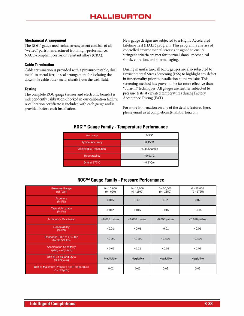
ROC Gauge Designs• Quartz transducer
• Hybrid technology
• Maximum 200°C operating temperature
• Multi-drop capability – up to seven gauges at 30,000 ft
downhole cable
• Dual sensor feed-through capability
• Improved shock and vibration performance
• 0.75-in. OD slimline design available
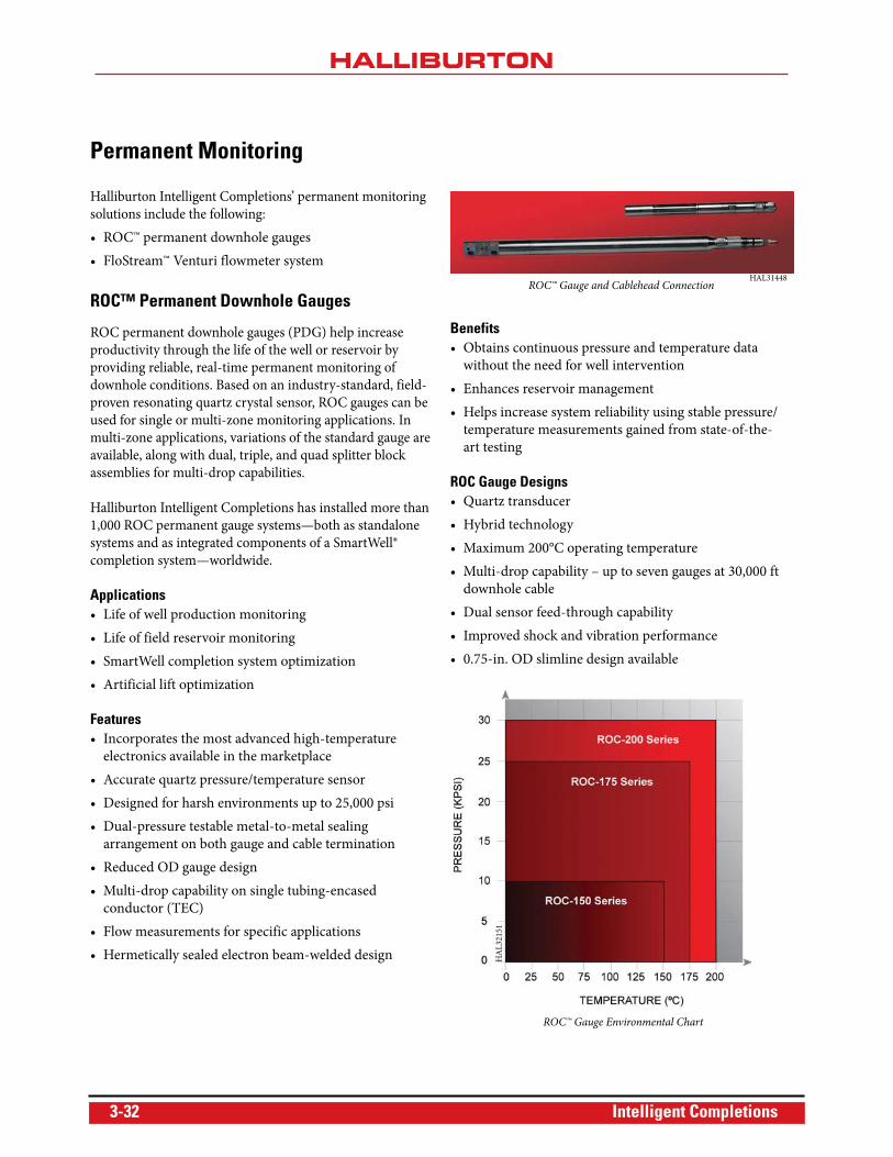
HAL31448ROC™ Gauge and Cablehead Connection
HA
L32
151
ROC™ Gauge Environmental Chart
3-32 Intelligent Completions
Mechanical ArrangementThe ROC™ gauge mechanical arrangement consists of all
“wetted” parts manufactured from high-performance,
NACE-compliant corrosion resistant alloys (CRA).
Cable TerminationCable termination is provided with a pressure-testable, dual
metal-to-metal ferrule seal arrangement for isolating the
downhole cable outer metal sheath from the well fluid.
TestingThe complete ROC gauge (sensor and electronic boards) is
independently calibration-checked in our calibration facility.
A calibration certificate is included with each gauge and is
provided before each installation.
New gauge designs are subjected to a Highly Accelerated
Lifetime Test (HALT) program. This program is a series of
controlled environmental stresses designed to ensure
stringent criteria are met for thermal shock, mechanical
shock, vibration, and thermal aging.
During manufacture, all ROC gauges are also subjected to
Environmental Stress Screening (ESS) to highlight any defect
in functionality prior to installation at the wellsite. This
screening method has proven to be far more effective than
“burn-in” techniques. All gauges are further subjected to
pressure tests at elevated temperatures during Factory
Acceptance Testing (FAT).
For more information on any of the details featured here,
please email us at [email protected].
ROC™ Gauge Family - Temperature Performance
Accuracy 0.5°C
Typical Accuracy 0.15°C
Achievable Resolution <0.005°C/sec
Repeatability <0.01°C
Drift at 177ºC <0.1°C/yr
ROC™ Gauge Family - Pressure Performance
Pressure Rangepsi (bar)
0 - 10,000(0 - 690)
0 - 16,000(0 - 1100)
0 - 20,000(0 - 1380)
0 - 25,000(0 - 1725)
Accuracy (% FS) 0.015 0.02 0.02 0.02
Typical Accuracy (% FS) 0.012 0.015 0.015 0.015
Achievable Resolution <0.006 psi/sec <0.008 psi/sec <0.008 psi/sec <0.010 psi/sec
Repeatability (% FS) <0.01 <0.01 <0.01 <0.01
Response Time to FS Step (for 99.5% FS) <1 sec <1 sec <1 sec <1 sec
Acceleration Sensitivity (psi/g – any axis) <0.02 <0.02 <0.02 <0.02
Drift at 14 psi and 25°C (% FS/year) Negligible Negligible Negligible Negligible
Drift at Maximum Pressure and Temperature (% FS/year) 0.02 0.02 0.02 0.02
Intelligent Completions 3-33
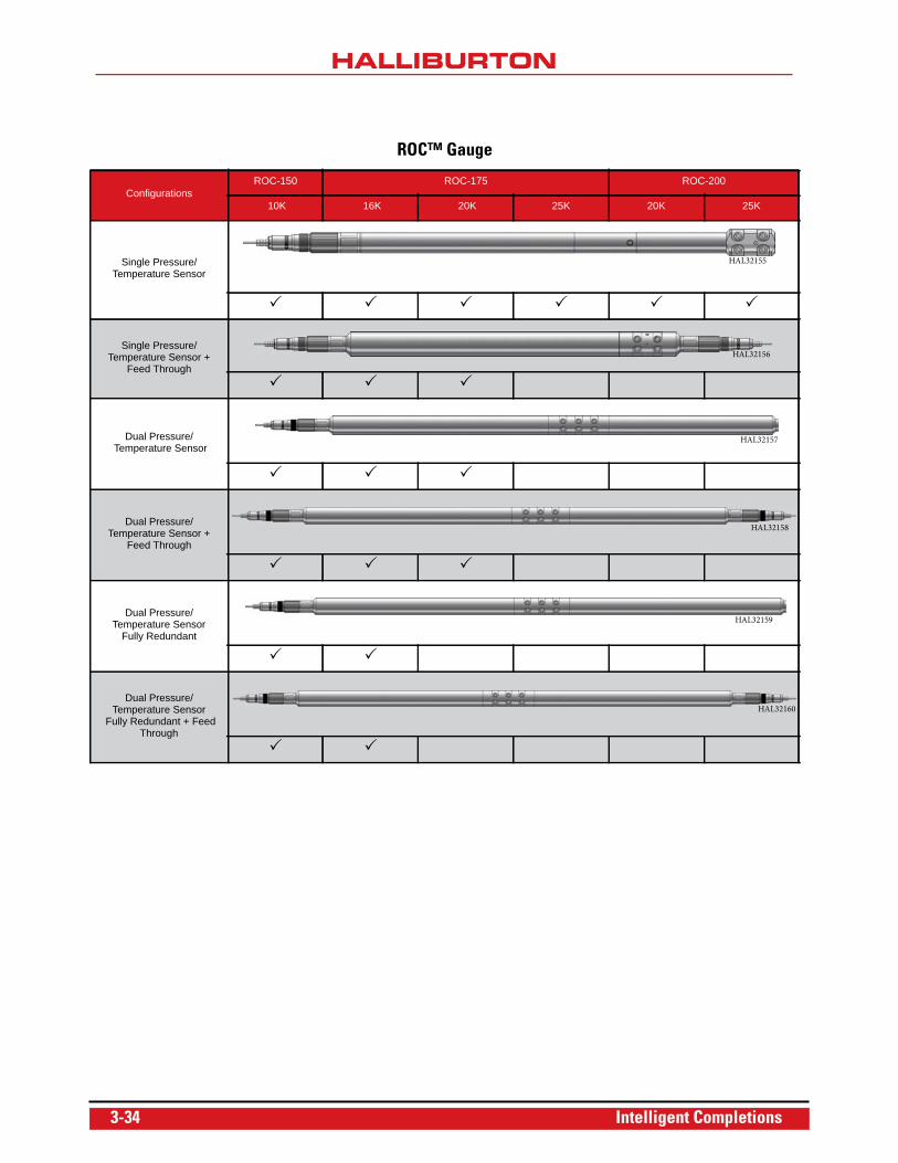
ROC™ Gauge
ConfigurationsROC-150 ROC-175 ROC-200
10K 16K 20K 25K 20K 25K
Single Pressure/Temperature Sensor
Single Pressure/Temperature Sensor +
Feed Through
Dual Pressure/ Temperature Sensor
Dual Pressure/ Temperature Sensor +
Feed Through
Dual Pressure/ Temperature Sensor
Fully Redundant
Dual Pressure/ Temperature Sensor
Fully Redundant + Feed Through
HAL32155
HAL32156
HAL32157
HAL32158
HAL32159
HAL32160
3-34 Intelligent Completions
ROC™ Gauge Mandrels
All Halliburton Intelligent Completions ROC™ gauge
mandrels are sized to match the tubing string in which they
are to be run in accordance with API 5CT. The gauge
mandrel fully contains the ROC gauge assemblies within the
mandrel body slots, protecting the gauges from damage. The
gauge mandrels are machined from solid bar stock and are
profiled to avoid snagging during run-in-hole operations.
The gauge mandrels are also provided with premium threads
to match that of the completion.
The gauges communicate with the production bore through
ports in the sidewall. The gauges are mounted in custom-
profiled locations on the mandrels, and a metal-to-metal seal
with elastomeric backup seals provides a high-confidence
permanent pressure seal between the mandrel and gauge.
All gauge mandrels are fully tested prior to delivery. This
testing includes:
• NDT - MPI to ASTM E709:94
• UT wall to ASME V SA V88
• Gauge-mount pressure testing
• Bore burst testing as per API 5CT to match that of the
tubing string
• High-pressure external testing on completed assembly
• Thread gauging and drift testing
FloStream™ Venturi Flowmeter
The FloStream™ flowmeter incorporates a Venturi flowmeter
profile and two high-accuracy ROC quartz pressure and
temperature gauges. An optional third ROC gauge can be
added to enable continuous calculation of downhole fluid
density to be made.
Benefits• Accurate downhole flow rate measurement
• No moving parts mean high reliability
• Based on proven ROC permanent gauge technology
• Wireline-retrievable Venturi section option allows
measurement of changing flow rates without a workover
• Absolute pressure measurement allows redundancy in
pressure measurement and a wide flow rate
measurement window
• Minimum pressure loss over whole system
Accuracy and Resolution• Accuracy of +5% can be achieved, provided the limits of
the Venturi flowmeter principle are not exceeded
• Resolution of <0.1% of full scale
Operational ParametersThe Venturi flowmeter mandrel can be machined to a specific
profile or can incorporate a wireline-retrievable Venturi
flowmeter section, which can allow for:
• Changing of the Venturi flowmeter should the flow rate
change significantly
• Replacement should the Venturi profile become worn
• Removal of the restriction imposed should it become
necessary to carry out some well maintenance operation
below the flowmeter
Intelligent Completions 3-35
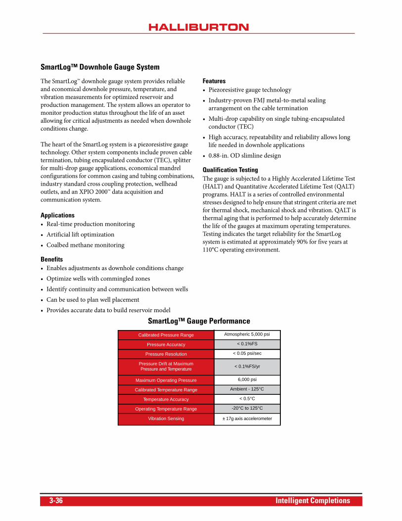
SmartLog™ Downhole Gauge System
The SmartLog™ downhole gauge system provides reliable
and economical downhole pressure, temperature, and
vibration measurements for optimized reservoir and
production management. The system allows an operator to
monitor production status throughout the life of an asset
allowing for critical adjustments as needed when downhole
conditions change.
The heart of the SmartLog system is a piezoresistive gauge
technology. Other system components include proven cable
termination, tubing encapsulated conductor (TEC), splitter
for multi-drop gauge applications, economical mandrel
configurations for common casing and tubing combinations,
industry standard cross coupling protection, wellhead
outlets, and an XPIO 2000™ data acquisition and
communication system.
Applications• Real-time production monitoring
• Artificial lift optimization
• Coalbed methane monitoring
Benefits• Enables adjustments as downhole conditions change
• Optimize wells with commingled zones
• Identify continuity and communication between wells
• Can be used to plan well placement
• Provides accurate data to build reservoir model
Features• Piezoresistive gauge technology
• Industry-proven FMJ metal-to-metal sealing
arrangement on the cable termination
• Multi-drop capability on single tubing-encapsulated
conductor (TEC)
• High accuracy, repeatability and reliability allows long
life needed in downhole applications
• 0.88-in. OD slimline design
Qualification TestingThe gauge is subjected to a Highly Accelerated Lifetime Test
(HALT) and Quantitative Accelerated Lifetime Test (QALT)
programs. HALT is a series of controlled environmental
stresses designed to help ensure that stringent criteria are met
for thermal shock, mechanical shock and vibration. QALT is
thermal aging that is performed to help accurately determine
the life of the gauges at maximum operating temperatures.
Testing indicates the target reliability for the SmartLog
system is estimated at approximately 90% for five years at
110°C operating environment.
SmartLog™ Gauge Performance
Calibrated Pressure Range Atmospheric 5,000 psi
Pressure Accuracy < 0.1%FS
Pressure Resolution < 0.05 psi/sec
Pressure Drift at MaximumPressure and Temperature < 0.1%FS/yr
Maximum Operating Pressure 6,000 psi
Calibrated Temperature Range Ambient - 125°C
Temperature Accuracy < 0.5°C
Operating Temperature Range -20°C to 125°C
Vibration Sensing ± 17g axis accelerometer
3-36 Intelligent Completions
Chemical Injection System
Halliburton Intelligent Completions chemical injection
applications include:
• Scale
• Asphaltines
• Emulsions
• Hydrates
• Defoaming
• Paraffin
• Scavengers
• Corrosion
• Demulsifiers
There are two variations of chemical injection mandrels:
• Deep-set nipple mandrel – A robust one-piece machined
design utilizing the same design criteria as the
permanent downhole gauge mandrel for use in
deepwater or critical applications
• Welded pup nipple mandrel – Designed for use in
shallow set, non-deviated wells, or land applications
Features• Dual check valve (burst disk option available)
• Externally testable connections
• Welded construction check valve body
• Check valve material to suit application
Benefits• Subsea, platform, and land applications
• Cost effective
• Multi-line conveyance
Dual Check ValveThe chemical injection systems include dual check valves,
providing redundant checks (one hard seat and one soft seat).
The connection to the chemical injection line uses primary
and backup ferrules to provide improved sealing and physical
strength. The check valve body is a welded construction to
further reduce the possibility of tubing/annular leak.
The check valve is available in a variety of materials to best
suit well conditions with externally testable connections to
reduce makeup time.
Control Line, Chemical Injection Lines, and ClampsMulti-line conveyance is supplied as a standard service and
includes all necessary spooler units, hydraulic slip rings,
pumps, filters, and sheave wheels. Intelligent Completions can
provide full pump capability for operations during tripping in
hole and for commissioning the well. Control lines and
chemical injection lines are available in all common materials
with tubing sizes and wall thicknesses to suit all applications.
The lines can be provided bare, encapsulated with other lines,
or with a tubing-encapsulated connector (TEC) line. Lines are
supplied fluid filled, flushed, and filtered to the required NAS
standard. Cast steel or press steel clamps are used to protect
the control lines.
Intelligent Completions 3-37
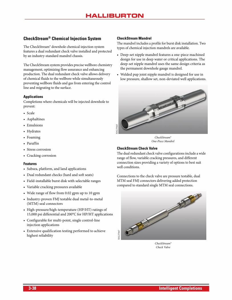
CheckStream® Chemical Injection System
The CheckStream® downhole chemical injection system
features a dual redundant check valve installed and protected
by an industry-standard mandrel chassis.
The CheckStream system provides precise wellbore chemistry
management, optimizing flow assurance and enhancing
production. The dual redundant check valve allows delivery
of chemical fluids to the wellbore while simultaneously
preventing wellbore fluids and gas from entering the control
line and migrating to the surface.
ApplicationsCompletions where chemicals will be injected downhole to
prevent:
• Scale
• Asphaltines
• Emulsions
• Hydrates
• Foaming
• Paraffin
• Stress corrosion
• Cracking corrosion
Features• Subsea, platform, and land applications
• Dual redundant checks (hard and soft seats)
• Field-installable burst disk with selectable ranges
• Variable cracking pressures available
• Wide range of flow from 0.02 gpm up to 10 gpm
• Industry-proven FMJ testable dual metal-to-metal
(MTM) seal connectors
• High-pressure/high-temperature (HP/HT) ratings of
15,000 psi differential and 200°C for HP/HT applications
• Configurable for multi-point, single control-line
injection applications
• Extensive qualification testing performed to achieve
highest reliability
CheckStream MandrelThe mandrel includes a profile for burst disk installation. Two
types of chemical injection mandrels are available.
• Deep-set nipple mandrel features a one-piece machined
design for use in deep water or critical applications. The
deep-set nipple mandrel uses the same design criteria as
the permanent downhole gauge mandrel.
• Welded pup joint nipple mandrel is designed for use in
low pressure, shallow set, non-deviated well applications.
CheckStream Check ValveThe dual redundant check valve configurations include a wide
range of flow, variable cracking pressures, and different
connection sizes providing a variety of options to best suit
well conditions.
Connections to the check valve are pressure testable, dual
MTM seal FMJ connectors delivering added protection
compared to standard single MTM seal connections.
HA
L37
643
CheckStream®
One-Piece Mandrel
CheckStream®
Check Valve
HA
L37
647
3-38 Intelligent Completions
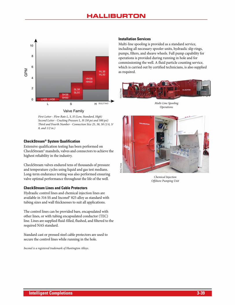
CheckStream® System QualificationExtensive qualification testing has been performed on
CheckStream® mandrels, valves and connectors to achieve the
highest reliability in the industry.
CheckStream valves endured tens of thousands of pressure
and temperature cycles using liquid and gas test medians.
Long-term endurance testing was also performed ensuring
valve optimal performance throughout the life of the well.
CheckStream Lines and Cable ProtectorsHydraulic control lines and chemical injection lines are
available in 316 SS and Inconel® 825 alloy as standard with
tubing sizes and wall thicknesses to suit all applications.
The control lines can be provided bare, encapsulated with
other lines, or with tubing encapsulated conductor (TEC)
line. Lines are supplied fluid-filled, flushed, and filtered to the
required NAS standard.
Standard cast or pressed steel cable protectors are used to
secure the control lines while running in the hole.
Inconel is a registered trademark of Huntington Alloys.
Installation ServicesMulti-line spooling is provided as a standard service,
including all necessary spooler units, hydraulic slip rings,
pumps, filters, and sheave wheels. Full pump capability for
operations is provided during running in hole and for
commissioning the well. A fluid particle counting service,
which is carried out by certified technicians, is also supplied
as required.
First Letter - Flow Rate L, S, H (Low, Standard, High)
Second Letter - Cracking Pressure L, H (50 psi and 500 psi)
Third and Fourth Number - Connection Size 25, 38, 50 (1/4, 3/
8, and 1/2 in.)
HAL37645 Multi-Line Spooling
Operations
HA
L37
646
Chemical Injection
Offshore Pumping Unit
HA
L37
644
Intelligent Completions 3-39
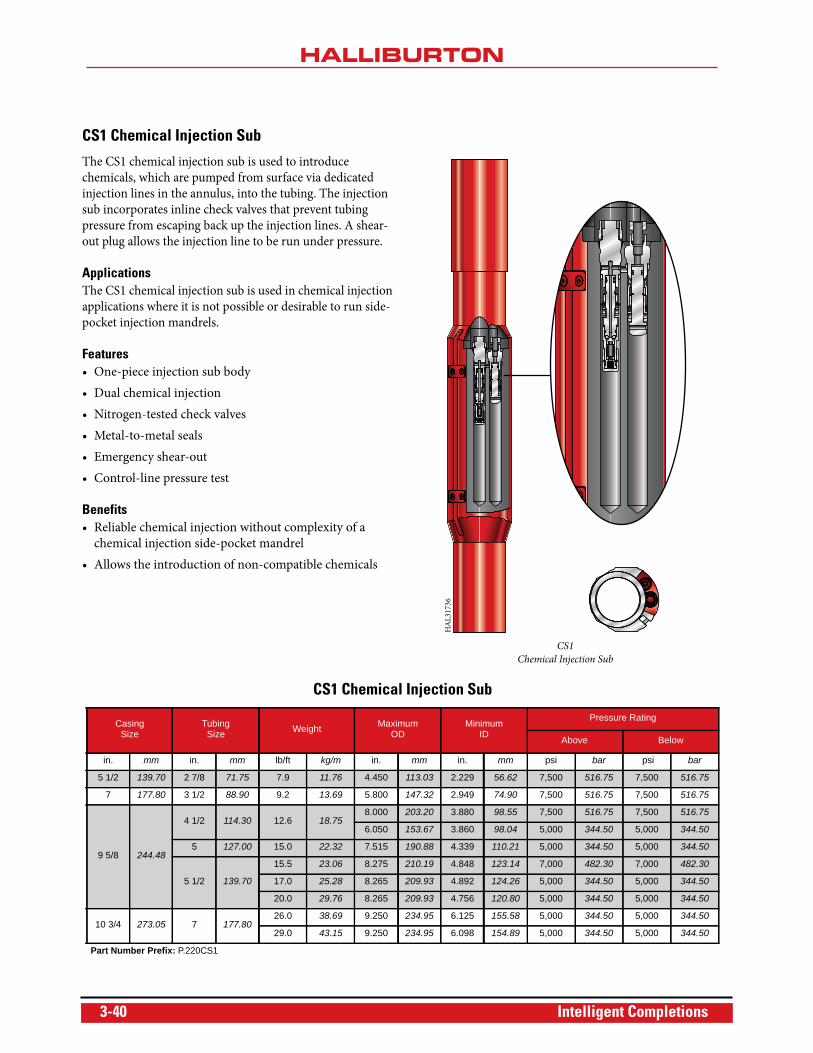
CS1 Chemical Injection Sub
The CS1 chemical injection sub is used to introduce
chemicals, which are pumped from surface via dedicated
injection lines in the annulus, into the tubing. The injection
sub incorporates inline check valves that prevent tubing
pressure from escaping back up the injection lines. A shear-
out plug allows the injection line to be run under pressure.
ApplicationsThe CS1 chemical injection sub is used in chemical injection
applications where it is not possible or desirable to run side-
pocket injection mandrels.
Features• One-piece injection sub body
• Dual chemical injection
• Nitrogen-tested check valves
• Metal-to-metal seals
• Emergency shear-out
• Control-line pressure test
Benefits• Reliable chemical injection without complexity of a
chemical injection side-pocket mandrel
• Allows the introduction of non-compatible chemicals
CS1
Chemical Injection Sub
HA
L31
736
CS1 Chemical Injection Sub
Casing Size
TubingSize Weight Maximum
ODMinimum
ID
Pressure Rating
Above Below
in. mm in. mm lb/ft kg/m in. mm in. mm psi bar psi bar
5 1/2 139.70 2 7/8 71.75 7.9 11.76 4.450 113.03 2.229 56.62 7,500 516.75 7,500 516.75
7 177.80 3 1/2 88.90 9.2 13.69 5.800 147.32 2.949 74.90 7,500 516.75 7,500 516.75
9 5/8 244.48
4 1/2 114.30 12.6 18.758.000 203.20 3.880 98.55 7,500 516.75 7,500 516.75
6.050 153.67 3.860 98.04 5,000 344.50 5,000 344.50
5 127.00 15.0 22.32 7.515 190.88 4.339 110.21 5,000 344.50 5,000 344.50
5 1/2 139.70
15.5 23.06 8.275 210.19 4.848 123.14 7,000 482.30 7,000 482.30
17.0 25.28 8.265 209.93 4.892 124.26 5,000 344.50 5,000 344.50
20.0 29.76 8.265 209.93 4.756 120.80 5,000 344.50 5,000 344.50
10 3/4 273.05 7 177.8026.0 38.69 9.250 234.95 6.125 155.58 5,000 344.50 5,000 344.50
29.0 43.15 9.250 234.95 6.098 154.89 5,000 344.50 5,000 344.50
Part Number Prefix: P.220CS1
3-40 Intelligent Completions
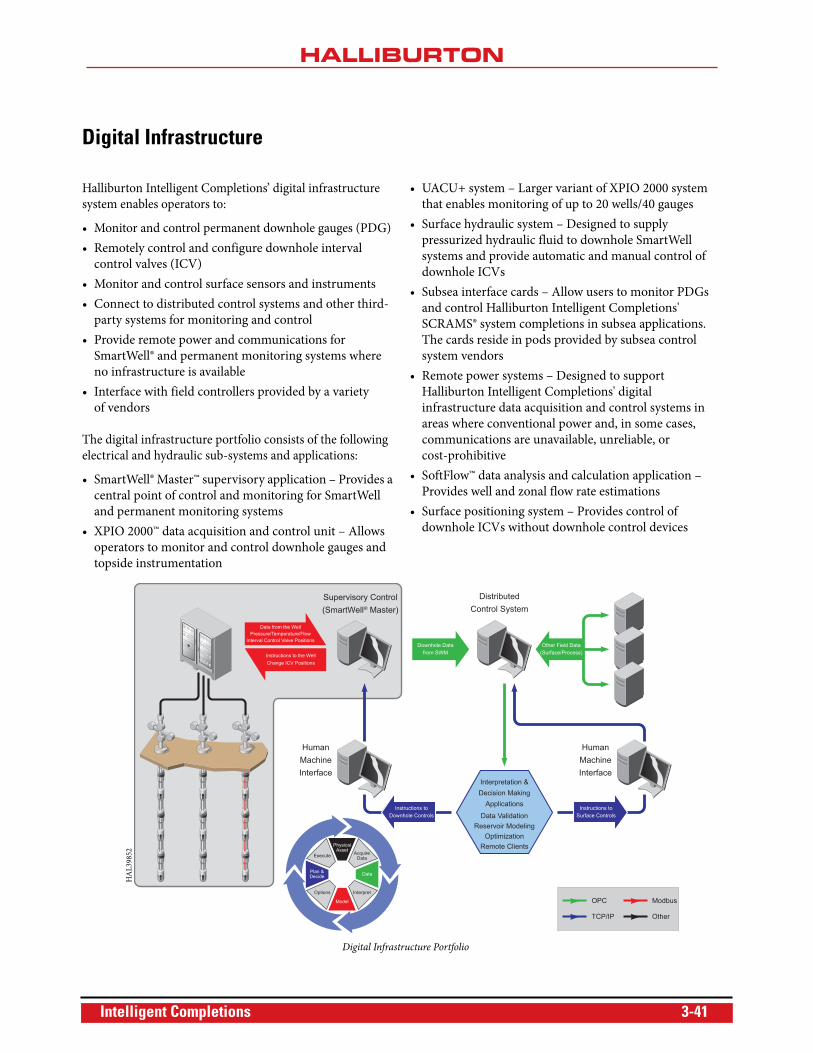
Digital Infrastructure
Halliburton Intelligent Completions’ digital infrastructure
system enables operators to:
• Monitor and control permanent downhole gauges (PDG)
• Remotely control and configure downhole interval
control valves (ICV)
• Monitor and control surface sensors and instruments
• Connect to distributed control systems and other third-
party systems for monitoring and control
• Provide remote power and communications for
SmartWell® and permanent monitoring systems where
no infrastructure is available
• Interface with field controllers provided by a variety
of vendors
The digital infrastructure portfolio consists of the following
electrical and hydraulic sub-systems and applications:
• SmartWell® Master™ supervisory application – Provides a
central point of control and monitoring for SmartWell
and permanent monitoring systems
• XPIO 2000™ data acquisition and control unit – Allows
operators to monitor and control downhole gauges and
topside instrumentation
• UACU+ system – Larger variant of XPIO 2000 system
that enables monitoring of up to 20 wells/40 gauges
• Surface hydraulic system – Designed to supply
pressurized hydraulic fluid to downhole SmartWell
systems and provide automatic and manual control of
downhole ICVs
• Subsea interface cards – Allow users to monitor PDGs
and control Halliburton Intelligent Completions'
SCRAMS® system completions in subsea applications.
The cards reside in pods provided by subsea control
system vendors
• Remote power systems – Designed to support
Halliburton Intelligent Completions' digital
infrastructure data acquisition and control systems in
areas where conventional power and, in some cases,
communications are unavailable, unreliable, or
cost-prohibitive
• SoftFlow™ data analysis and calculation application –
Provides well and zonal flow rate estimations
• Surface positioning system – Provides control of
downhole ICVs without downhole control devices
Data from the WellPressure/Temperature/Flow
Interval Control Valve Positions
Instructions to the WellChange ICV Positions
Supervisory Control(SmartWell® Master)
HumanMachineInterface
HumanMachineInterface
OPC
DistributedControl System
Instructions toDownhole Controls
Other Field Data(Surface/Process)
Instructions toSurface Controls
Downhole Datafrom SWM
Interpretation &Decision Making
Applications
Data ValidationReservoir Modeling
OptimizationRemote Clients
TCP/IP
Modbus
Other
AcquireData
Interpret
Data
Execute
Options
Plan &Decide
Model
PhysicalAsset
Digital Infrastructure Portfolio
HA
L39
852
Intelligent Completions 3-41
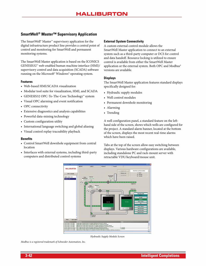
SmartWell® Master™ Supervisory Application
The SmartWell® Master™ supervisory application for the
digital infrastructure product line provides a central point of
control and monitoring for SmartWell and permanent
monitoring systems.
The SmartWell Master application is based on the ICONICS
GENESIS32™ web-enabled human machine interface (HMI)/
supervisory control and data acquisition (SCADA) software
running on the Microsoft® Windows® operating system.
Features• Web-based HMI/SCADA visualization
• Modular tool suite for visualization, HMI, and SCADA
• GENESIS32 OPC-To-The-Core Technology™ system
• Visual OPC alarming and event notification
• OPC connectivity
• Extensive diagnostics and analysis capabilities
• Powerful data-mining technology
• Custom configuration utility
• International language switching and global aliasing
• Visual control replay traceability playback
Benefits• Control SmartWell downhole equipment from central
location
• Interfaces with external systems, including third-party
computers and distributed control systems
External System ConnectivityA custom external control module allows the
SmartWell Master application to connect to an external
system such as a third-party computer or DCS for control
and data handoff. Resource locking is utilized to ensure
control is available from either the SmartWell Master
application or the external system. Both OPC and Modbus®
versions are available.
DisplaysThe SmartWell Master application features standard displays
specifically designed for:
• Hydraulic supply modules
• Well control modules
• Permanent downhole monitoring
• Alarming
• Trending
A well configuration panel, a standard feature on the left-
hand side of the screen, shows which wells are configured for
the project. A standard alarm banner, located at the bottom
of the screen, displays the most recent real-time alarms
which have been raised.
Tabs at the top of the screen allow easy switching between
displays. Various hardware configurations are available,
including standalone PC and rack-mount server with
retractable VDU/keyboard/mouse unit.
Modbus is a registered trademark of Schneider Automation, Inc.
Hydraulic Supply Module Screen
3-42 Intelligent Completions
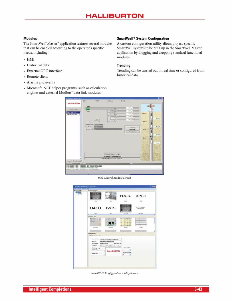
ModulesThe SmartWell® Master™ application features several modules
that can be enabled according to the operator's specific
needs, including:
• HMI
• Historical data
• External OPC interface
• Remote client
• Alarms and events
• Microsoft .NET helper programs, such as calculation
engines and external Modbus® data link modules
SmartWell® System ConfigurationA custom configuration utility allows project-specific
SmartWell systems to be built up in the SmartWell Master
application by dragging and dropping standard functional
modules.
TrendingTrending can be carried out in real time or configured from
historical data.
Well Control Module Screen
SmartWell® Configuration Utility Screen
Intelligent Completions 3-43
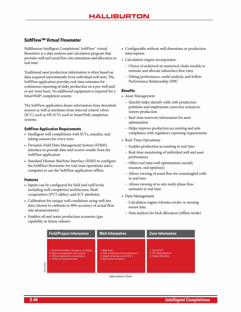
SoftFlow™ Virtual Flowmeter
Halliburton Intelligent Completions’ SoftFlow™ virtual
flowmeter is a data analysis and calculation program that
provides well and zonal flow rate estimation and allocation in
real time.
Traditional asset production information is often based on
data acquired intermittently from individual well tests. The
SoftFlow application provides real-time estimates for
continuous reporting of daily production on a per-well and/
or per-zone basis. No additional equipment is required for a
SmartWell® completion system.
The SoftFlow application draws information from downhole
sensors as well as attributes from interval control valves
(ICV), such as HS-ICVs used in SmartWell completion
systems.
SoftFlow Application Requirements• Intelligent well completions with ICVs, annulus, and
tubing sensors for every zone
• Dynamic Field Data Management System (FDMS)
interface to provide data and receive results from the
SoftFlow application
• Standard Human Machine Interface (HMI) to configure
the SoftFlow flowmeter for real-time operations and a
computer to use the SoftFlow application offline
Features• Inputs can be configured for field and well levels
including well completion architecture, fluid
composition (PVT tables), and ICV attributes
• Calibration for unique well conditions using well test
data (shown to calibrate to 90% accuracy of actual flow
rate measurements)
• Enables oil and water production scenarios (gas
capability in future release)
• Configurable without well downtime or production
interruption
• Calculation engine incorporates:
– Choice of analytical or numerical choke models to
estimate and allocate subsurface flow rates
– Tubing performance, nodal analysis, and Inflow
Performance Relationship (IPR)
Benefits• Asset Management
– Quickly helps identify wells with production
problems and implements corrective actions to
restore production
– Real-time reservoir information for asset
optimization
– Helps improve production accounting and aids
compliance with regulatory reporting requirements
• Real-Time Operations
– Enables production accounting in real time
– Real-time monitoring of individual well and asset
performance
– Offers real-time well optimization (model,
measure, and optimize)
– Allows viewing of zonal flow for commingled wells
in real time
– Allows viewing of in-situ multi-phase flow
estimates in real time
• Data Management
– Calculation engine tolerates erratic or missing
sensor data
– Data analysis for back allocation (offline mode)
Field/Project Information
1. Field information (single or multiple)2. Data management and quality3. Define calculation parameters4. Units of measurements
1. Well type2. Well properties and architecture3. Depth of sensors and ICV’s4. Well administration
1. Zone PVT2. ICV Specification3. Node definition
Well Information Zone Information
Information Chart
HA
L32
364
3-44 Intelligent Completions
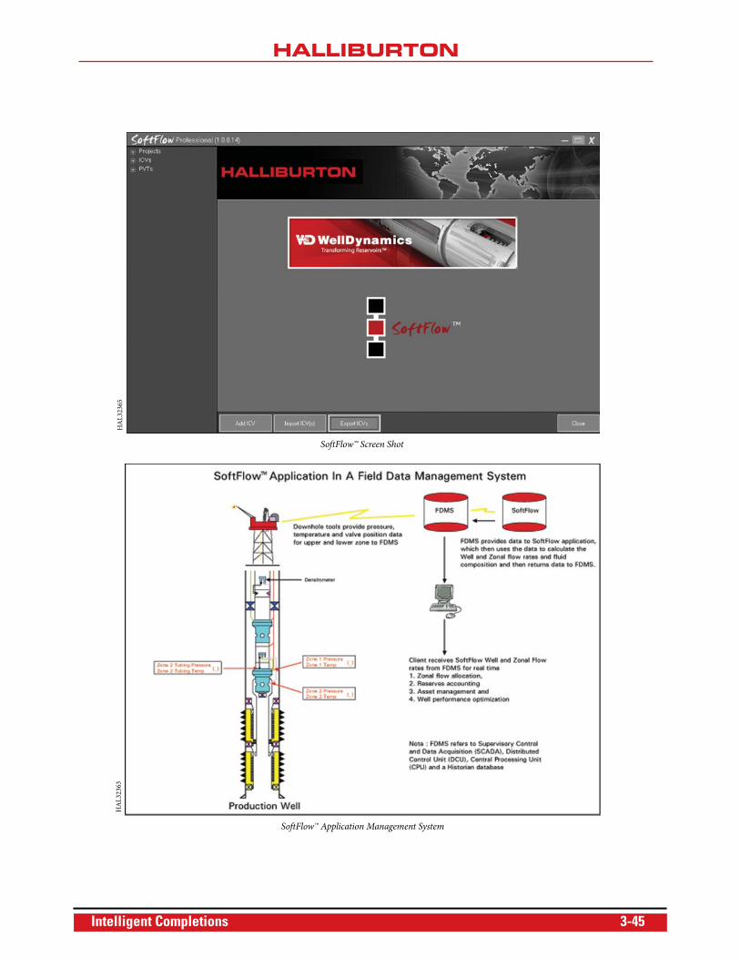
SoftFlow™ Screen Shot
SoftFlow™ Application Management System
HA
L32
365
HA
L32
363
Intelligent Completions 3-45
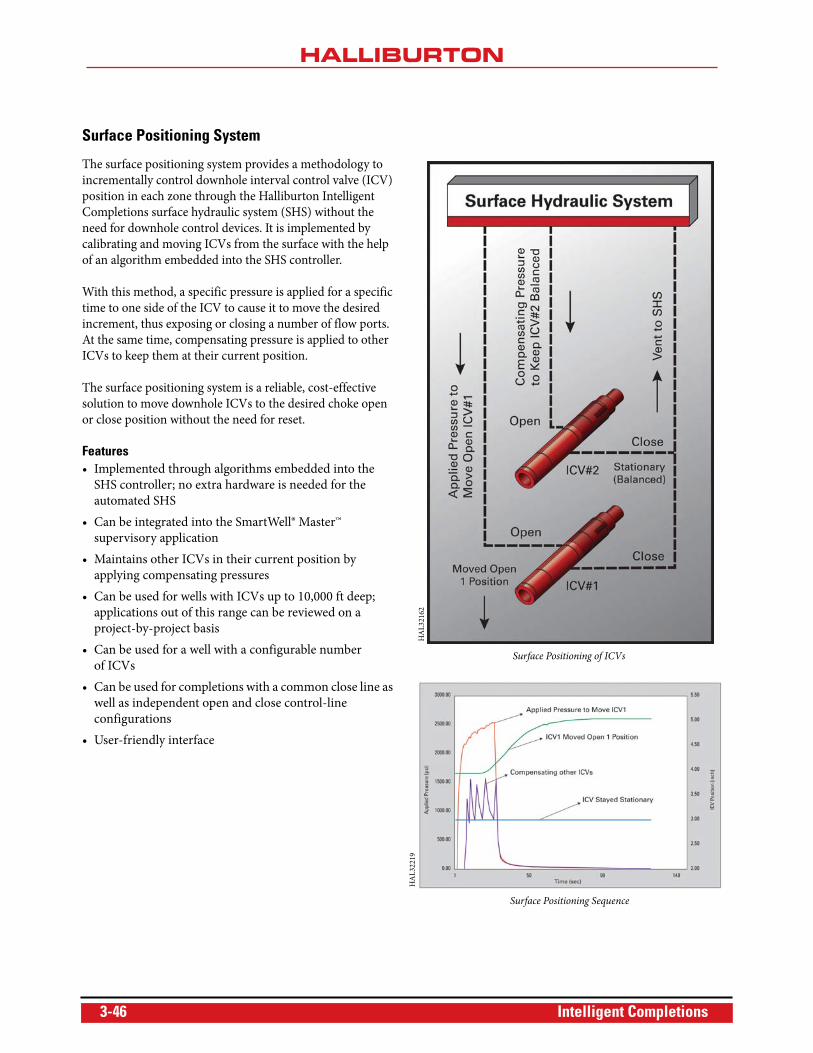
Surface Positioning System
The surface positioning system provides a methodology to
incrementally control downhole interval control valve (ICV)
position in each zone through the Halliburton Intelligent
Completions surface hydraulic system (SHS) without the
need for downhole control devices. It is implemented by
calibrating and moving ICVs from the surface with the help
of an algorithm embedded into the SHS controller.
With this method, a specific pressure is applied for a specific
time to one side of the ICV to cause it to move the desired
increment, thus exposing or closing a number of flow ports.
At the same time, compensating pressure is applied to other
ICVs to keep them at their current position.
The surface positioning system is a reliable, cost-effective
solution to move downhole ICVs to the desired choke open
or close position without the need for reset.
Features• Implemented through algorithms embedded into the
SHS controller; no extra hardware is needed for the
automated SHS
• Can be integrated into the SmartWell® Master™
supervisory application
• Maintains other ICVs in their current position by
applying compensating pressures
• Can be used for wells with ICVs up to 10,000 ft deep;
applications out of this range can be reviewed on a
project-by-project basis
• Can be used for a well with a configurable number
of ICVs
• Can be used for completions with a common close line as
well as independent open and close control-line
configurations
• User-friendly interface
Surface Positioning of ICVs
HA
L32
162
Surface Positioning Sequence
HA
L32
219
3-46 Intelligent Completions
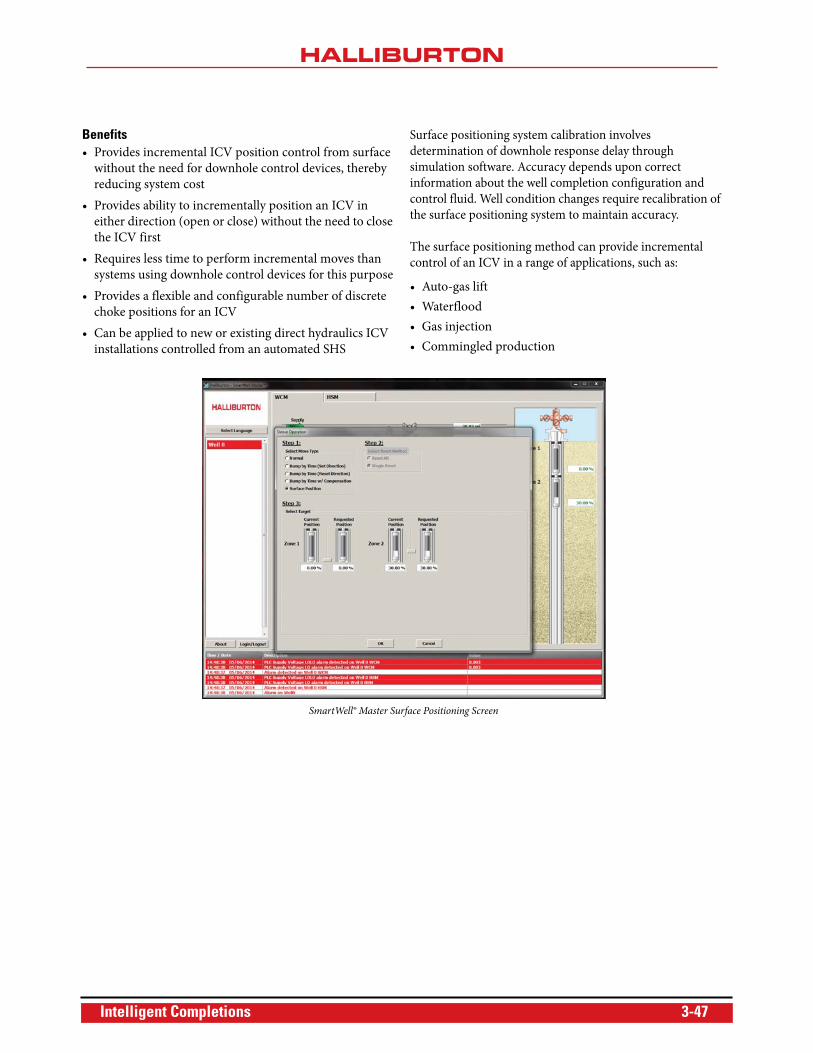
Benefits• Provides incremental ICV position control from surface
without the need for downhole control devices, thereby
reducing system cost
• Provides ability to incrementally position an ICV in
either direction (open or close) without the need to close
the ICV first
• Requires less time to perform incremental moves than
systems using downhole control devices for this purpose
• Provides a flexible and configurable number of discrete
choke positions for an ICV
• Can be applied to new or existing direct hydraulics ICV
installations controlled from an automated SHS
Surface positioning system calibration involves
determination of downhole response delay through
simulation software. Accuracy depends upon correct
information about the well completion configuration and
control fluid. Well condition changes require recalibration of
the surface positioning system to maintain accuracy.
The surface positioning method can provide incremental
control of an ICV in a range of applications, such as:
• Auto-gas lift
• Waterflood
• Gas injection
• Commingled production
SmartWell® Master Surface Positioning Screen
Intelligent Completions 3-47
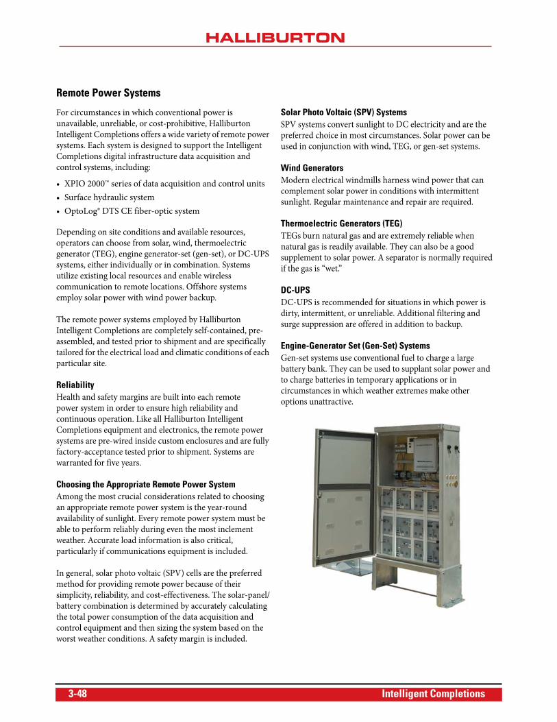
Remote Power Systems
For circumstances in which conventional power is
unavailable, unreliable, or cost-prohibitive, Halliburton
Intelligent Completions offers a wide variety of remote power
systems. Each system is designed to support the Intelligent
Completions digital infrastructure data acquisition and
control systems, including:
• XPIO 2000™ series of data acquisition and control units
• Surface hydraulic system
• OptoLog® DTS CE fiber-optic system
Depending on site conditions and available resources,
operators can choose from solar, wind, thermoelectric
generator (TEG), engine generator-set (gen-set), or DC-UPS
systems, either individually or in combination. Systems
utilize existing local resources and enable wireless
communication to remote locations. Offshore systems
employ solar power with wind power backup.
The remote power systems employed by Halliburton
Intelligent Completions are completely self-contained, pre-
assembled, and tested prior to shipment and are specifically
tailored for the electrical load and climatic conditions of each
particular site.
ReliabilityHealth and safety margins are built into each remote
power system in order to ensure high reliability and
continuous operation. Like all Halliburton Intelligent
Completions equipment and electronics, the remote power
systems are pre-wired inside custom enclosures and are fully
factory-acceptance tested prior to shipment. Systems are
warranted for five years.
Choosing the Appropriate Remote Power SystemAmong the most crucial considerations related to choosing
an appropriate remote power system is the year-round
availability of sunlight. Every remote power system must be
able to perform reliably during even the most inclement
weather. Accurate load information is also critical,
particularly if communications equipment is included.
In general, solar photo voltaic (SPV) cells are the preferred
method for providing remote power because of their
simplicity, reliability, and cost-effectiveness. The solar-panel/
battery combination is determined by accurately calculating
the total power consumption of the data acquisition and
control equipment and then sizing the system based on the
worst weather conditions. A safety margin is included.
Solar Photo Voltaic (SPV) SystemsSPV systems convert sunlight to DC electricity and are the
preferred choice in most circumstances. Solar power can be
used in conjunction with wind, TEG, or gen-set systems.
Wind GeneratorsModern electrical windmills harness wind power that can
complement solar power in conditions with intermittent
sunlight. Regular maintenance and repair are required.
Thermoelectric Generators (TEG)TEGs burn natural gas and are extremely reliable when
natural gas is readily available. They can also be a good
supplement to solar power. A separator is normally required
if the gas is “wet.”
DC-UPSDC-UPS is recommended for situations in which power is
dirty, intermittent, or unreliable. Additional filtering and
surge suppression are offered in addition to backup.
Engine-Generator Set (Gen-Set) SystemsGen-set systems use conventional fuel to charge a large
battery bank. They can be used to supplant solar power and
to charge batteries in temporary applications or in
circumstances in which weather extremes make other
options unattractive.
3-48 Intelligent Completions
XPIO 2000™ Data Acquisition and Control Unit
Halliburton Intelligent Completions' XPIO 2000™ data
acquisition and control system allows operators to monitor
and control downhole gauges and topside instrumentation.
Acquiring data at a rate of 0.5 seconds per gauge, the XPIO
2000 system is available in a range of capacities, from 1 well/4
gauges to 4 wells/8 gauges. A larger variant within the XPIO
2000 range is the UACU+, which extends capacity up to 20
wells/40 gauges for a single unit. The UACU+ is fitted with a
permanent downhole gauge interface card (PDGIC) module
for each downhole channel.
Downhole cable inputs are independent and fully isolated.
Features• Five channels of 4-20mA analog inputs (12-bit)
• Four channels of 4-20mA analog outputs (16-bit)
• 4MB of flash memory
• Modbus® RTU protocol support via RS-485 or RS-232
port, or via TCP/IP port
• Modem communications support via the RS-232 port
• Two relay contacts
• Communications programs that allow full configuration
of the unit
Benefits• Control Halliburton Intelligent Completions' permanent
downhole gauges (PDG), including the ROC™ family,
SmartLog™ gauges, and surface instruments
• Store and display data from PDGs and surface sensors
• Interface with external systems, including third-party
computers and distributed control systems
Analog InputsThe XPIO 2000 system features five channels of 4-20mA
inputs (12-bit) that are fully configurable using the
XPIO 2000 PC program. Users can set the offset, span, and
units of measure, and then can choose to monitor them on
the display or log them into memory.
Analog OutputsThe XPIO 2000 system features four channels of 4-20mA
outputs (16-bit). Users can select the pressure, temperature,
span, and offset of a permanent downhole gauge, and the
XPIO 2000 system will drive the translated value onto an
output as it is decoded from down hole.
Modbus is a registered trademark of Schneider Automation, Inc.
Memory LoggingThe XPIO 2000 system comes standard with 4MB of flash memory. A SanDisk CompactFlash® card option extends the memory by 2GB.
The 4MB memory can hold pressure and temperature data from one gauge at one-minute updates for more than three months. The 2GB option extends memory capacity to hold pressure and temperature data from two gauges at one-second updates for more than a year.
Data is retrieved via an RS-232 port using the supplied PC program or by file transfer protocol (FTP) over the TCP/IP link and can easily be imported to other applications such as a spreadsheet. Data is logged to memory at a maximum rate of once per second.
Both the standard XPIO and UACU+ are available in NEMA4X enclosure and 19-in. rack mount versions. The 19-in. rack mount UACU+ has a 10-well/20-gauge capacity.
Serial CommunicationsThe XPIO 2000 system supports Modbus® RTU protocol via its RS-485 or RS-232 port or via its TCP/IP port. These interfaces are fully configurable in terms of parity, baud rate, etc. As a slave device, the XPIO 2000 system provides gauge data (i.e., pressure and temperature) that can be polled as well as data from any of the 4-20mA inputs. Time and date are also available.
Modem SupportThe XPIO 2000 system supports modem communications via the RS-232 port. Users may dial into the unit using the supplied PC program, or use the port to talk to the Modbus system over a radio modem, cellular modem, or regular modem.
Pressure-Controlled Relay ContactsThe XPIO 2000 system comes with two relay contacts (1/2A at 115VAC) which are controlled by software. When a selected gauge's pressure rises above or falls below a set pressure, the contact is closed. This feature is ideal for alarms and/or pump control.
Web-Installed PC ApplicationThe XPIO 2000 system comes with a web-installed application that provides for full configuration of the unit as well as data memory retrieval, real-time logging of data to the computer hard drive, and real-time data trending.
Intelligent Completions 3-49
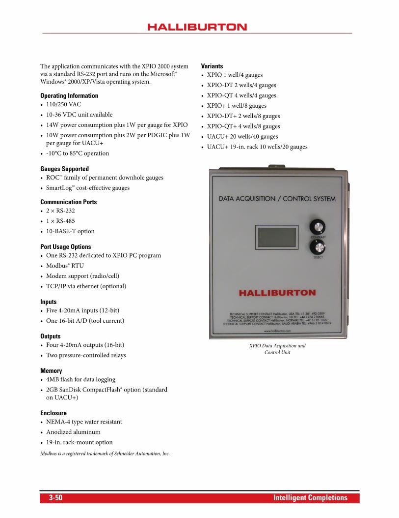
The application communicates with the XPIO 2000 system via a standard RS-232 port and runs on the Microsoft® Windows® 2000/XP/Vista operating system.
Operating Information• 110/250 VAC
• 10-36 VDC unit available
• 14W power consumption plus 1W per gauge for XPIO
• 10W power consumption plus 2W per PDGIC plus 1W
per gauge for UACU+
• -10°C to 85°C operation
Gauges Supported• ROC™ family of permanent downhole gauges
• SmartLog™ cost-effective gauges
Communication Ports• 2 × RS-232
• 1 × RS-485
• 10-BASE-T option
Port Usage Options• One RS-232 dedicated to XPIO PC program
• Modbus® RTU
• Modem support (radio/cell)
• TCP/IP via ethernet (optional)
Inputs• Five 4-20mA inputs (12-bit)
• One 16-bit A/D (tool current)
Outputs• Four 4-20mA outputs (16-bit)
• Two pressure-controlled relays
Memory• 4MB flash for data logging
• 2GB SanDisk CompactFlash® option (standard
on UACU+)
Enclosure• NEMA-4 type water resistant
• Anodized aluminum
• 19-in. rack-mount option
Modbus is a registered trademark of Schneider Automation, Inc.
Variants• XPIO 1 well/4 gauges
• XPIO-DT 2 wells/4 gauges
• XPIO-QT 4 wells/4 gauges
• XPIO+ 1 well/8 gauges
• XPIO-DT+ 2 wells/8 gauges
• XPIO-QT+ 4 wells/8 gauges
• UACU+ 20 wells/40 gauges
• UACU+ 19-in. rack 10 wells/20 gauges
XPIO Data Acquisition and
Control Unit
3-50 Intelligent Completions
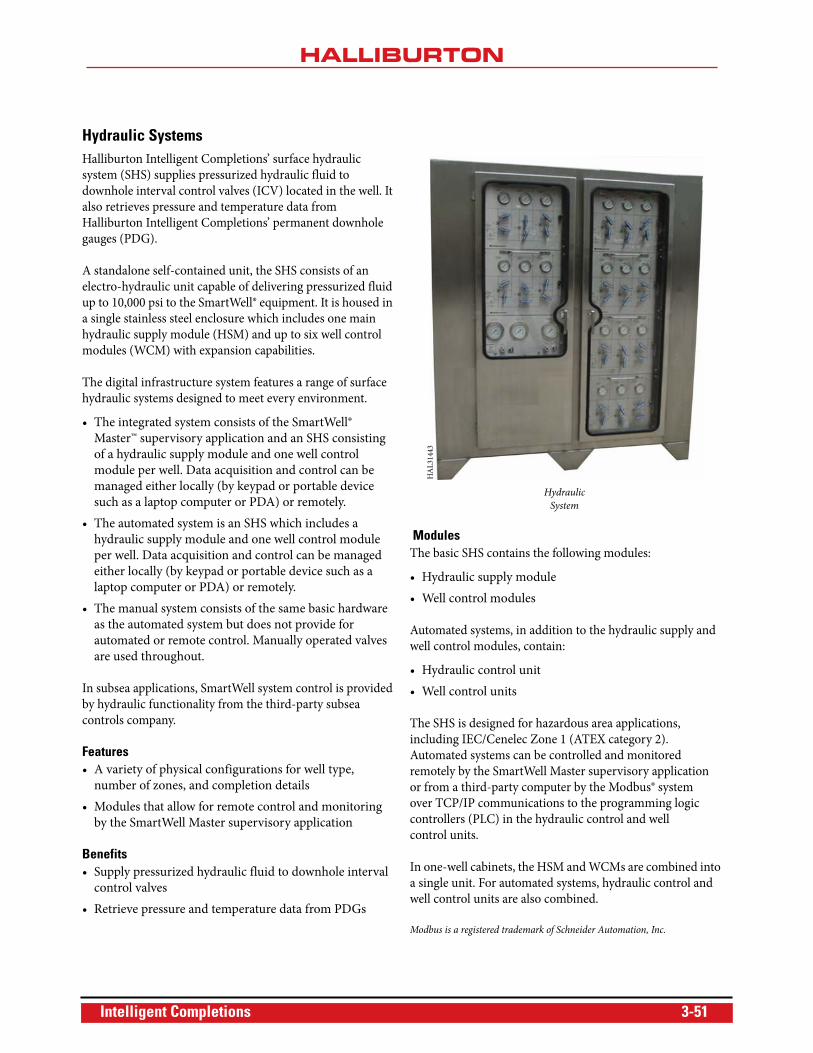
Hydraulic SystemsHalliburton Intelligent Completions’ surface hydraulic
system (SHS) supplies pressurized hydraulic fluid to
downhole interval control valves (ICV) located in the well. It
also retrieves pressure and temperature data from
Halliburton Intelligent Completions’ permanent downhole
gauges (PDG).
A standalone self-contained unit, the SHS consists of an
electro-hydraulic unit capable of delivering pressurized fluid
up to 10,000 psi to the SmartWell® equipment. It is housed in
a single stainless steel enclosure which includes one main
hydraulic supply module (HSM) and up to six well control
modules (WCM) with expansion capabilities.
The digital infrastructure system features a range of surface
hydraulic systems designed to meet every environment.
• The integrated system consists of the SmartWell®
Master™ supervisory application and an SHS consisting
of a hydraulic supply module and one well control
module per well. Data acquisition and control can be
managed either locally (by keypad or portable device
such as a laptop computer or PDA) or remotely.
• The automated system is an SHS which includes a
hydraulic supply module and one well control module
per well. Data acquisition and control can be managed
either locally (by keypad or portable device such as a
laptop computer or PDA) or remotely.
• The manual system consists of the same basic hardware
as the automated system but does not provide for
automated or remote control. Manually operated valves
are used throughout.
In subsea applications, SmartWell system control is provided
by hydraulic functionality from the third-party subsea
controls company.
Features• A variety of physical configurations for well type,
number of zones, and completion details
• Modules that allow for remote control and monitoring
by the SmartWell Master supervisory application
Benefits• Supply pressurized hydraulic fluid to downhole interval
control valves
• Retrieve pressure and temperature data from PDGs
ModulesThe basic SHS contains the following modules:
• Hydraulic supply module
• Well control modules
Automated systems, in addition to the hydraulic supply and
well control modules, contain:
• Hydraulic control unit
• Well control units
The SHS is designed for hazardous area applications,
including IEC/Cenelec Zone 1 (ATEX category 2).
Automated systems can be controlled and monitored
remotely by the SmartWell Master supervisory application
or from a third-party computer by the Modbus® system
over TCP/IP communications to the programming logic
controllers (PLC) in the hydraulic control and well
control units.
In one-well cabinets, the HSM and WCMs are combined into
a single unit. For automated systems, hydraulic control and
well control units are also combined.
Modbus is a registered trademark of Schneider Automation, Inc.
Hydraulic
System
HA
L31
443
Intelligent Completions 3-51
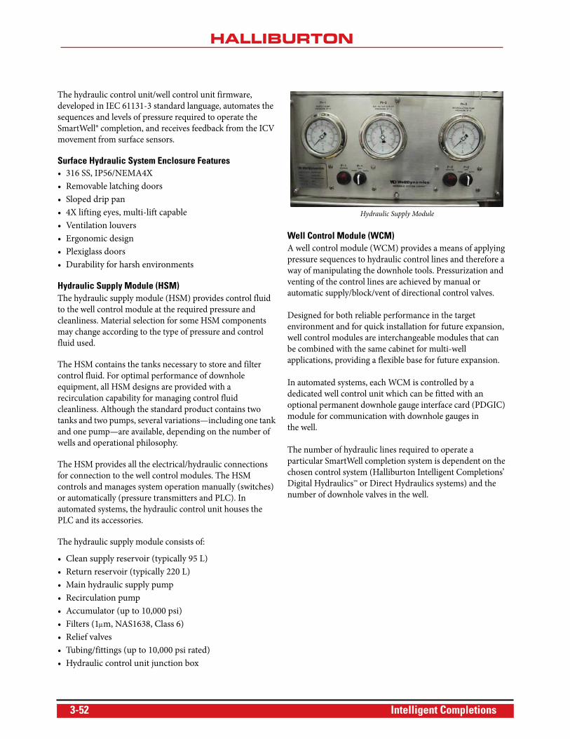
The hydraulic control unit/well control unit firmware,
developed in IEC 61131-3 standard language, automates the
sequences and levels of pressure required to operate the
SmartWell® completion, and receives feedback from the ICV
movement from surface sensors.
Surface Hydraulic System Enclosure Features• 316 SS, IP56/NEMA4X
• Removable latching doors
• Sloped drip pan
• 4X lifting eyes, multi-lift capable
• Ventilation louvers
• Ergonomic design
• Plexiglass doors
• Durability for harsh environments
Hydraulic Supply Module (HSM)The hydraulic supply module (HSM) provides control fluid
to the well control module at the required pressure and
cleanliness. Material selection for some HSM components
may change according to the type of pressure and control
fluid used.
The HSM contains the tanks necessary to store and filter
control fluid. For optimal performance of downhole
equipment, all HSM designs are provided with a
recirculation capability for managing control fluid
cleanliness. Although the standard product contains two
tanks and two pumps, several variations—including one tank
and one pump—are available, depending on the number of
wells and operational philosophy.
The HSM provides all the electrical/hydraulic connections
for connection to the well control modules. The HSM
controls and manages system operation manually (switches)
or automatically (pressure transmitters and PLC). In
automated systems, the hydraulic control unit houses the
PLC and its accessories.
The hydraulic supply module consists of:
• Clean supply reservoir (typically 95 L)
• Return reservoir (typically 220 L)
• Main hydraulic supply pump
• Recirculation pump
• Accumulator (up to 10,000 psi)
• Filters (1m, NAS1638, Class 6)
• Relief valves
• Tubing/fittings (up to 10,000 psi rated)
• Hydraulic control unit junction box
Hydraulic Supply Module
Well Control Module (WCM)A well control module (WCM) provides a means of applying
pressure sequences to hydraulic control lines and therefore a
way of manipulating the downhole tools. Pressurization and
venting of the control lines are achieved by manual or
automatic supply/block/vent of directional control valves.
Designed for both reliable performance in the target
environment and for quick installation for future expansion,
well control modules are interchangeable modules that can
be combined with the same cabinet for multi-well
applications, providing a flexible base for future expansion.
In automated systems, each WCM is controlled by a
dedicated well control unit which can be fitted with an
optional permanent downhole gauge interface card (PDGIC)
module for communication with downhole gauges in
the well.
The number of hydraulic lines required to operate a
particular SmartWell completion system is dependent on the
chosen control system (Halliburton Intelligent Completions’
Digital Hydraulics™ or Direct Hydraulics systems) and the
number of downhole valves in the well.
3-52 Intelligent Completions
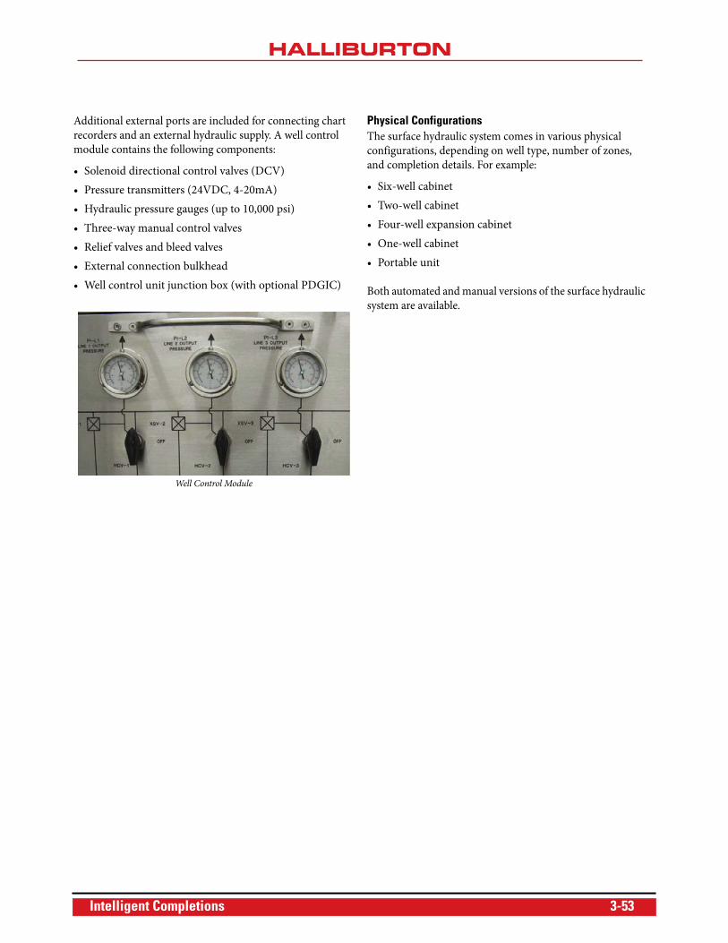
Additional external ports are included for connecting chart
recorders and an external hydraulic supply. A well control
module contains the following components:
• Solenoid directional control valves (DCV)
• Pressure transmitters (24VDC, 4-20mA)
• Hydraulic pressure gauges (up to 10,000 psi)
• Three-way manual control valves
• Relief valves and bleed valves
• External connection bulkhead
• Well control unit junction box (with optional PDGIC)
Well Control Module
Physical ConfigurationsThe surface hydraulic system comes in various physical
configurations, depending on well type, number of zones,
and completion details. For example:
• Six-well cabinet
• Two-well cabinet
• Four-well expansion cabinet
• One-well cabinet
• Portable unit
Both automated and manual versions of the surface hydraulic
system are available.
Intelligent Completions 3-53
Subsea Interface Cards
Halliburton Intelligent Completions offers a range of subsea
interface cards that enable users to monitor permanent
downhole gauges (PDG) and control SCRAMS® surface
controlled reservoir analysis and management system
completions. Each subsea interface card resides in the pod
provided by the respective subsea controls vendor.
VetcoGray Dual Gauge Interface CardHalliburton Intelligent Completions' VetcoGray dual gauge
interface card is compatible with the VetcoGray-type
SEM2000 subsea control module, which features a single
downhole channel that provides communications and power
to the ROC™ family of gauges. It operates in either “Analog
Gauge” or “Digital Gauge” mode.
The card has been subjected to an extensive environmental
qualification program, including tests for:
• Temperature soak
• Temperature cycling
• Sine swept vibration
• Random vibration
• Non-operational shock
Functional card integration testing in the SEM2000 pod was
carried out at VetcoGray's premises in Nailsea, U.K. The card
has been deployed in the VetcoGray pod on major projects
for various operators, including Statoil and ENI.
Cameron Dual Gauge Interface CardHalliburton Intelligent Completions' Cameron dual gauge
interface card is compatible with the generic Cameron subsea
pod. Featuring a single downhole channel that provides
communications and power to the ROC™ gauge family,
the card can operate in either “Analog Gauge” or “Digital
Gauge” mode.
Cameron dual gauge interface card firmware includes a
timeout feature on the gauge communications, ensuring the
card will disconnect power to the downhole gauges if the pod
processor has not communicated with the card for more than
the timeout period. This feature is important in Cameron
dual-SEM pods, where gauge outputs from the interface card
in each SEM are connected together.
The card has been subjected to an extensive environmental
qualification program, including tests for:
• Temperature soak
• Temperature cycling
• Sine swept vibration
• Random vibration
• Non-operational shock
The card underwent extensive integration testing to
Cameron procedure X065418-07-01 at Cameron's premises
in Celle, Germany.
FMC Dual Gauge Interface CardThe Halliburton Intelligent Completions' FMC dual gauge
interface card is compatible with the FMC KS150 subsea
electronics module. The card features a single downhole
channel that provides communications and power to the
ROC gauge family and can operate in either “Analog Gauge”
or “Digital Gauge” mode.
The FMC card was subjected to an extensive environmental
qualification program, including tests for:
• Sine swept vibration
• Shock
• Thermal cycling
• Thermal dwell
The card underwent extensive integration testing at the FMC
premises in Kongsberg, Norway. An older card design, the
FMC digital gauge interface card, is still used exclusively in
Gulf of Mexico projects for a major customer. It has a single
downhole channel providing communications and power to
ROC digital gauges.
Aker Solutions Dual Interface CardHalliburton Intelligent Completions' Aker Solutions dual
gauge interface card is compatible with the Aker Solutions
iCon (formerly 5th Generation) subsea control module. It
has a single downhole channel, providing communications
and power to the ROC family of gauges and can operate in
either “Analog Gauge” or “Digital Gauge” mode.
Unlike other interface cards, the Aker Solutions dual gauge
interface card uses a Hypertac® edge connector rather than a
DIN41612 Euro style connector. The card was subjected to
electromagnetic compatibility qualification testing specific to
Aker Solutions requirements, including:
• Emissions
• Immunity
• Electrical fast transients/burst immunity
Hypertac is a registered trademark of Smiths Interconnect.
3-54 Intelligent Completions