Embed Size (px)
Citation preview

Copyright © 2017 ComAp a.s. Prague, Czech Republic ComAp a.s., U Uranie 1612/14a, 170 00 Praha 7, Czech Republic Tel: +420 246 012 111 E-mail: [email protected], www.comap-control.com
Communication guide
InteliGen
InteliSys
InteliMains
Communication Guide for ComAp Controllers

Communication Guide, ©ComAp – July 2017 2 IGS-NT Communication Guide 07-2017.pdf
Table of contents
Table of contents ..................................................................................................................................... 2 Scope of the document ............................................................................................................................ 5 Definition of terms .................................................................................................................................... 6 Controllers communication capabilities ................................................................................................... 7
▪ IG/IS/IM-NTC-BB - Communications .................................................................................... 7 ▪ IG/IS/IM-NTC-BB - Terminals ............................................................................................... 8 ▪ IG/IS/IM-NTC-BB - Peripheral modules ................................................................................ 9 ▪ IG/IS/IM-NTC-BB - Jumpers settings .................................................................................. 10 ▪ IG/IM-NT-BB - Communication ........................................................................................... 11 ▪ IG/IM-NT-BB - Terminals .................................................................................................... 12 ▪ IG/IM-NT-BB - Peripheral modules ..................................................................................... 13 ▪ IG/IM-NT-BB - Jumpers settings ......................................................................................... 14 ▪ IG-NT - Communications, Terminals .................................................................................. 15 ▪ IG-NTC - Communications, Terminals ................................................................................ 16 ▪ IS-NT-BB - Communications, Terminals............................................................................. 17 ▪ IM-NT - Communications, Terminals .................................................................................. 18
Monitoring Local on site - Comap SW ................................................................................................... 19 ▪ Direct PC connection to Single gen-set ................................................................................ 19
RS232 connection .......................................................................................................................... 19 USB connection .............................................................................................................................. 20 RS485 connection .......................................................................................................................... 20 Ethernet connection (Direct) .......................................................................................................... 21 ▪ Direct PC connection to Multiple gen-sets ............................................................................ 23
RS485 connection .......................................................................................................................... 23 RS232/485 connection (I-LB+) ....................................................................................................... 24 USB connection via I-LB+ module ................................................................................................. 25 Ethernet connection via IB-NT ....................................................................................................... 26 Ethernet connection (Direct) .......................................................................................................... 27
Monitoring Local on site - MODBUS ..................................................................................................... 29 ▪ ModBus - Single gen-set ...................................................................................................... 29
RS232 ModBus .............................................................................................................................. 29 RS485 ModBus .............................................................................................................................. 30 Ethernet - MODBUS/TCP (Direct) .................................................................................................. 31 ▪ ModBus - Multiple gen-sets .................................................................................................. 32
RS485 – MODBUS ......................................................................................................................... 32 RS232/RS485 – MODBUS (I-LB+) ................................................................................................ 33 Ethernet - MODBUS (IB-NT) .......................................................................................................... 34 Ethernet - MODBUS/TCP (Direct) .................................................................................................. 35
Remote monitoring ................................................................................................................................ 36 ▪ Connection to Internet (Direct) .............................................................................................. 36 ▪ Internet connection via AirGate ............................................................................................ 38 ▪ WebSupervisor ..................................................................................................................... 40 ▪ Web interface ........................................................................................................................ 42 ▪ Internet connection via cellular network................................................................................ 47
Connection via Internet bridge IB-NT ............................................................................................. 47 ▪ Active Call ............................................................................................................................. 48 ▪ Active SMS ........................................................................................................................... 48
Active E-mail (SMS E-mail) ............................................................................................................ 49 ▪ Access Lock .......................................................................................................................... 50
Peripheral modules ................................................................................................................................ 51 ▪ Displays ................................................................................................................................ 51
InteliVision 12Touch display ........................................................................................................... 51 InteliVision 8 display ....................................................................................................................... 51 InteliVision 5 display ....................................................................................................................... 52
Communication Guide, ©ComAp – July 2017 3 IGS-NT Communication Guide 07-2017.pdf
▪ Comms extension - I-LB+ Local bridge ................................................................................ 52 ▪ I-CR Module for CAN Bus Extension .................................................................................... 55
I-LB ................................................................................................................................................. 56 ▪ I-CR-R Module for CAN Bus Redundancy............................................................................ 56
Appendix ................................................................................................................................................ 61 ▪ Communication cables.......................................................................................................... 61
RS232 cable ................................................................................................................................... 61 USB cable ...................................................................................................................................... 62 Ethernet cable ................................................................................................................................ 63 ▪ Recommended CAN/RS485 connection .............................................................................. 64
CAN bus connection....................................................................................................................... 64 CAN bus extension options ............................................................................................................ 65 RS485 connection .......................................................................................................................... 66 ▪ Converters ............................................................................................................................ 68
Converter RS232 RS485 ........................................................................................................... 68 RS232 Bluetooth adapter ............................................................................................................... 69 Converter USB RS232 .............................................................................................................. 69 Converter USB RS485 .............................................................................................................. 70 Converter CAN CAN .................................................................................................................. 70 Recommended optical USB extension cables ............................................................................... 71 Radio Link ...................................................................................................................................... 71 Converter Modbus RTU Profibus .............................................................................................. 72 Ethernet converter from twisted pair (UTP/STP) to optic ............................................................... 79 ▪ SMS message commands .................................................................................................... 80
Modbus Connection ............................................................................................................................... 85 ▪ Modbus Step by Step............................................................................................................ 85 ▪ Important setpoints in the controller ...................................................................................... 85
Modbus communication via RS232 – single controller .................................................................. 85 Modbus communication via RS485 ................................................................................................ 86 Modbus communication via RS485 – multiple controllers ............................................................. 86 Modbus communication via I-LB+ .................................................................................................. 87 Modbus communication via IB-NT ................................................................................................. 87
Modbus Communication ........................................................................................................................ 88 ▪ Data reading ......................................................................................................................... 88 ▪ Data writing ........................................................................................................................... 88
Modbus Protocol Description................................................................................................................. 90 ▪ Modbus TCP ......................................................................................................................... 90
Read Multiple Registers ................................................................................................................. 91 ▪ Modbus RTU ......................................................................................................................... 92
Read Multiple Registers ................................................................................................................. 93 Write Single Register...................................................................................................................... 93 Write Multiple Registers ................................................................................................................. 94 ▪ Alarm list reading .................................................................................................................. 95
Alarm list reading via Modbus ........................................................................................................ 95 ▪ History reading ...................................................................................................................... 97 ▪ Check field calculation .......................................................................................................... 98 ▪ How get numbers of ModBus communication objects .......................................................... 98 ▪ Reserved communication objects ....................................................................................... 100 ▪ Access to password protected objects ............................................................................... 101 ▪ Commands for IGS-NT ....................................................................................................... 102 ▪ Commands for IM-NT ......................................................................................................... 103
User Modbus ....................................................................................................................................... 105 Modbus Appendix ................................................................................................................................ 106
▪ Modbus Switches ................................................................................................................ 106 ▪ Data types ........................................................................................................................... 106 ▪ Communication status ........................................................................................................ 108 ▪ Error list ............................................................................................................................... 109
Examples of Modbus Communication ................................................................................................. 112 Battery voltage – reading (read multiple registers) ...................................................................... 112
Communication Guide, ©ComAp – July 2017 4 IGS-NT Communication Guide 07-2017.pdf
Values (Oil press, Water temp, Fuel level) – reading .................................................................. 113 Binary input - reading .................................................................................................................. 113 Password decode - reading ........................................................................................................ 113 Gen-set name - reading .............................................................................................................. 114 Engine state - reading .................................................................................................................. 114 Gear teeth – writing ...................................................................................................................... 115 Nominal Power – writing .............................................................................................................. 115 Mode – writing .............................................................................................................................. 115 Reset / Confirm Alarm .................................................................................................................. 116 Remote Switch 1 – Set (Remote Control 1) ................................................................................. 117 External Value1 – writing ............................................................................................................. 117 User & Password – in two steps .................................................................................................. 118 User & Password – in one step .................................................................................................... 119 Start the engine – in one step ...................................................................................................... 119 Start the engine – in two steps ..................................................................................................... 120 History – reading .......................................................................................................................... 120 AlarmList reading ......................................................................................................................... 121
Communication Guide, ©ComAp – July 2017 5 IGS-NT Communication Guide 07-2017.pdf
Scope of the document
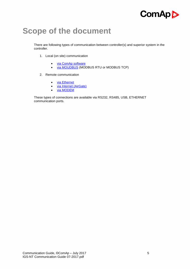
There are following types of communication between controller(s) and superior system in the controller.
1. Local (on site) communication
• via ComAp software
• via MOUDBUS (MODBUS RTU or MODBUS TCP)
2. Remote communication
• via Ethernet
• via Internet (AirGate)
• via MODEM
These types of connections are available via RS232, RS485, USB, ETHERNET communication ports.

Communication Guide, ©ComAp – July 2017 6 IGS-NT Communication Guide 07-2017.pdf
Definition of terms
Local connection Type of connection using direct connection on site via protocol of ports on the controller. Length of connection is given by protocol specification. Remote connection Type of connection using standard communication lines such as Internet, modem connection and GSM connection for communication between controller and other superior device. Comap Protocol Communication between PC with ComAp software (InteliMonitor, GenConfig) and controller is running on this protocol. 3rd party software Software using standardized protocol for sharing of data between particular systems (for example ModBus RTU, ModBus TCP etc.). Single gen-set communication This type of connection allows communication only with one controller. Communication with other controllers on site via this type of connection is not possible. Multiple gen-set communication This type of connection allows communication with more than one controller on site via single communication link. Monitoring Type of communication used for continuous displaying of process data and process control of the system. Configuration Type of communication used for writing of configuration file into the controller. Note: There are used some abbreviations for resolution of all hardware variations of IGS-NT controllers in this document. These abbreviations correspond with order codes of each HW variation.
InteliSys NTC Basebox IS-NTC-BB
InteliSys NT IS-NT-BB
InteliGen NTC Basebox IG-NTS-BB
InteliGen NT Basebox IG-NT-BB
InteliGen NTC IG-NTC
InteliGen NT IG-NT
InteliMains NTC Basebox IM-NTC-BB
InteliMains NT Basebox IM-NT-BB
InteliMains NT IM-NT
Hint: In abbreviation the “C” means “Communications” – controller with extended communication ports. The “Basebox” controller has not inbuilt LCD panel, it is recommended to use IV5, IV8 or IV12 remote display. Abbreviation “IGS-NT” stands for IG-NT or IS-NT and it is used to describe common features of both products.

Communication Guide, ©ComAp – July 2017 7 IGS-NT Communication Guide 07-2017.pdf
Controllers communication capabilities
IG/IS/IM-NTC-BB - Communications

Communication Guide, ©ComAp – July 2017 8 IGS-NT Communication Guide 07-2017.pdf
IG/IS/IM-NTC-BB - Terminals
Communication Guide, ©ComAp – July 2017 9 IGS-NT Communication Guide 07-2017.pdf
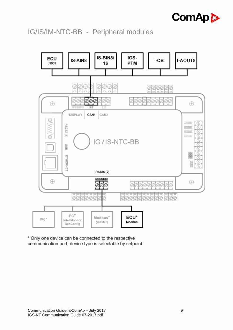
IG/IS/IM-NTC-BB - Peripheral modules

Communication Guide, ©ComAp – July 2017 10 IGS-NT Communication Guide 07-2017.pdf
IG/IS/IM-NTC-BB - Jumpers settings
Communication Guide, ©ComAp – July 2017 11 IGS-NT Communication Guide 07-2017.pdf
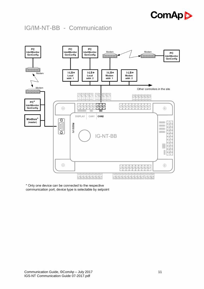
IG/IM-NT-BB - Communication
Communication Guide, ©ComAp – July 2017 12 IGS-NT Communication Guide 07-2017.pdf
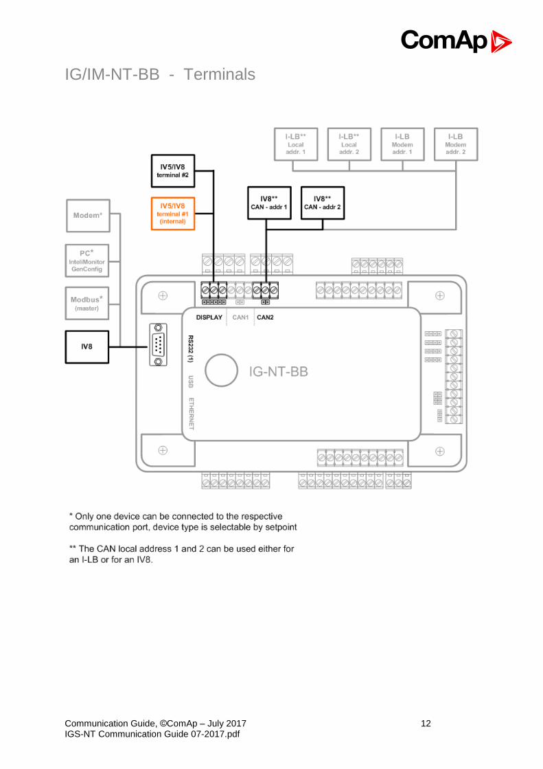
IG/IM-NT-BB - Terminals
Communication Guide, ©ComAp – July 2017 13 IGS-NT Communication Guide 07-2017.pdf
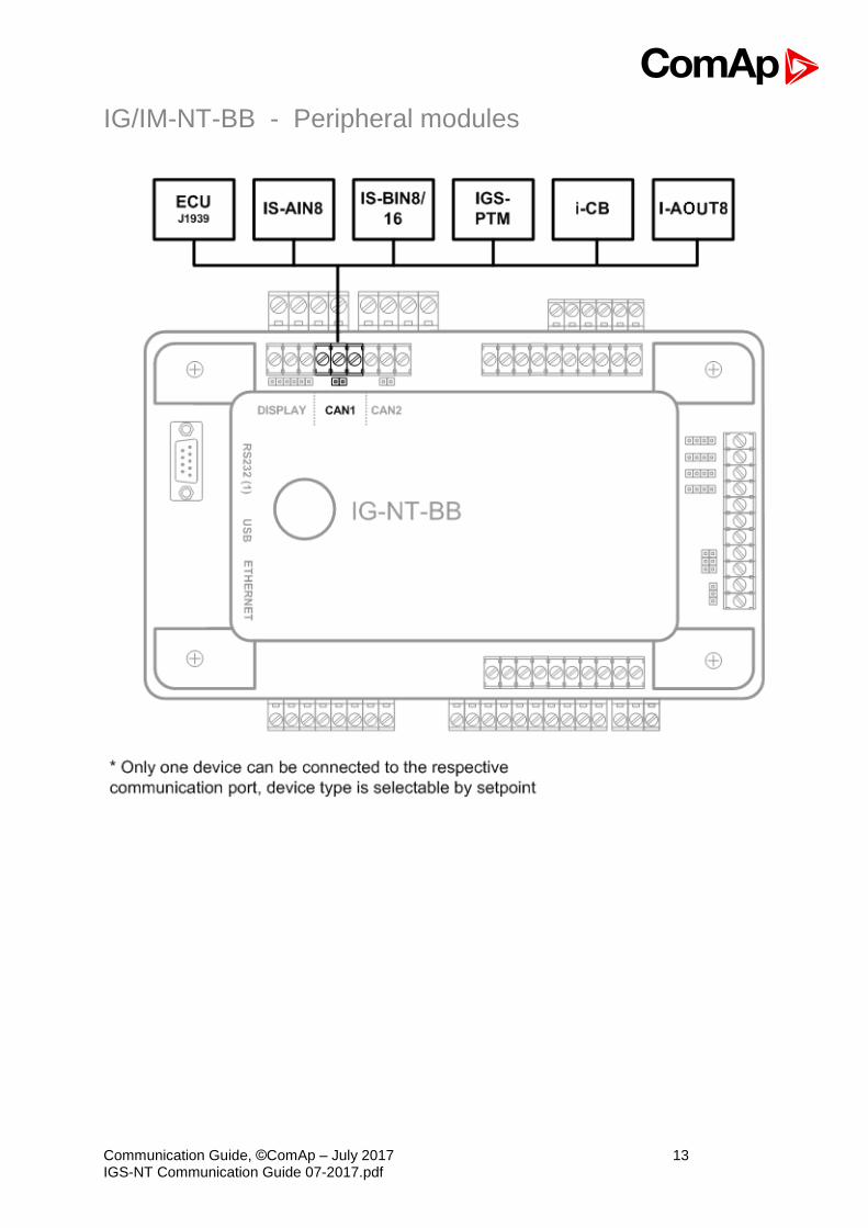
IG/IM-NT-BB - Peripheral modules
Communication Guide, ©ComAp – July 2017 14 IGS-NT Communication Guide 07-2017.pdf
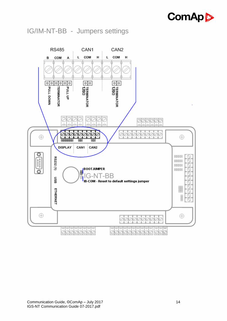
IG/IM-NT-BB - Jumpers settings
Communication Guide, ©ComAp – July 2017 15 IGS-NT Communication Guide 07-2017.pdf
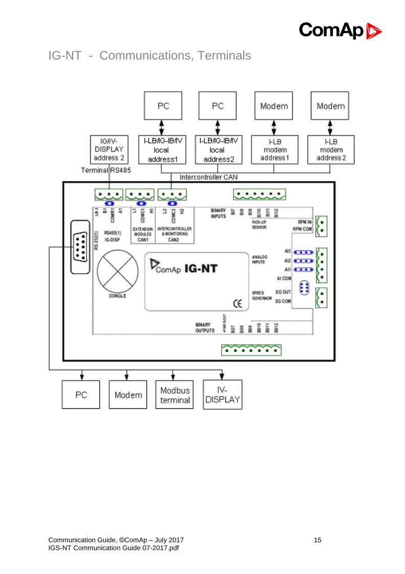
IG-NT - Communications, Terminals
Communication Guide, ©ComAp – July 2017 16 IGS-NT Communication Guide 07-2017.pdf
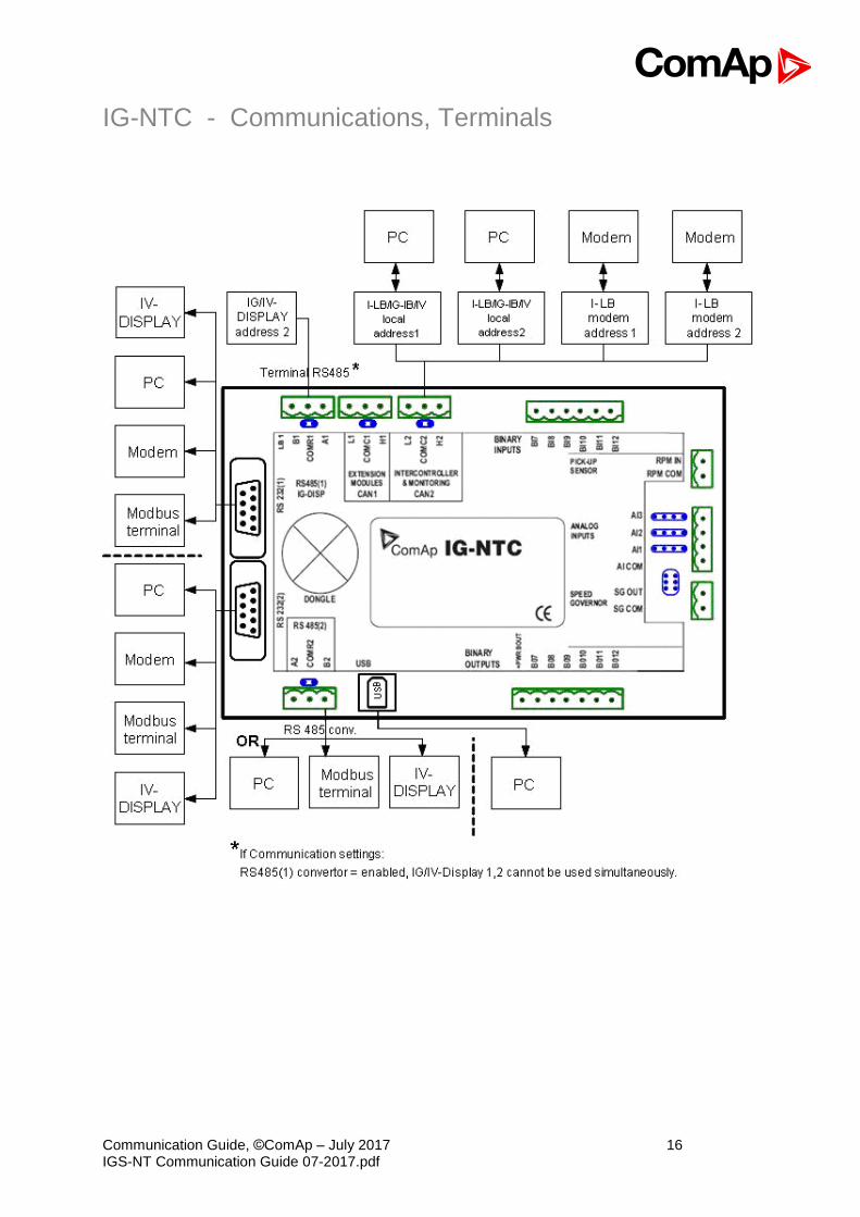
IG-NTC - Communications, Terminals

Communication Guide, ©ComAp – July 2017 17 IGS-NT Communication Guide 07-2017.pdf
IS-NT-BB - Communications, Terminals
Communication Guide, ©ComAp – July 2017 18 IGS-NT Communication Guide 07-2017.pdf
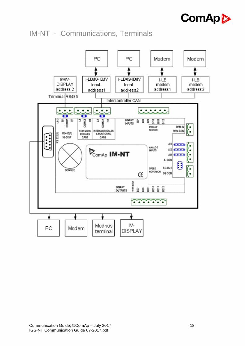
IM-NT - Communications, Terminals
Communication Guide, ©ComAp – July 2017 19 IGS-NT Communication Guide 07-2017.pdf
Monitoring Local on site - Comap SW
Direct PC connection to Single gen-set
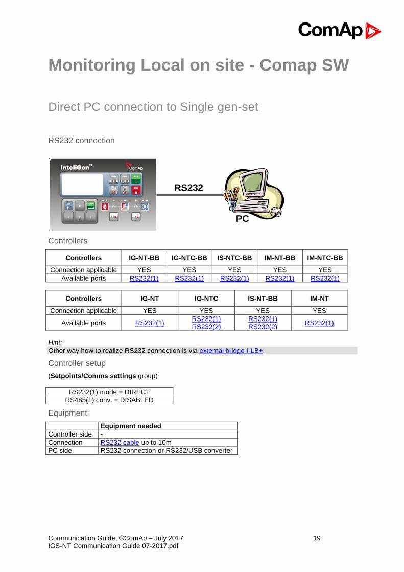
RS232 connection
RS232
PC
Controllers
Controllers IG-NT-BB IG-NTC-BB IS-NTC-BB IM-NT-BB IM-NTC-BB
Connection applicable YES YES YES YES YES
Available ports RS232(1) RS232(1) RS232(1) RS232(1) RS232(1)
Controllers IG-NT IG-NTC IS-NT-BB IM-NT
Connection applicable YES YES YES YES
Available ports RS232(1) RS232(1) RS232(2)
RS232(1) RS232(2)
RS232(1)
Hint: Other way how to realize RS232 connection is via external bridge I-LB+.
Controller setup
(Setpoints/Comms settings group)
RS232(1) mode = DIRECT
RS485(1) conv. = DISABLED
Equipment
Equipment needed
Controller side -
Connection RS232 cable up to 10m
PC side RS232 connection or RS232/USB converter
Communication Guide, ©ComAp – July 2017 20 IGS-NT Communication Guide 07-2017.pdf
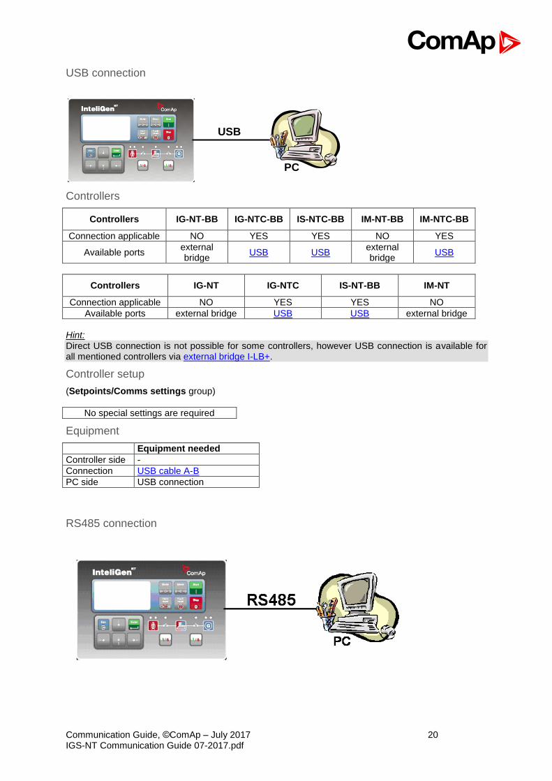
USB connection
USB
PC
Controllers
Controllers IG-NT-BB IG-NTC-BB IS-NTC-BB IM-NT-BB IM-NTC-BB
Connection applicable NO YES YES NO YES
Available ports external bridge
USB USB external bridge
USB
Controllers IG-NT IG-NTC IS-NT-BB IM-NT
Connection applicable NO YES YES NO
Available ports external bridge USB USB external bridge
Hint: Direct USB connection is not possible for some controllers, however USB connection is available for all mentioned controllers via external bridge I-LB+.
Controller setup
(Setpoints/Comms settings group)
No special settings are required
Equipment
Equipment needed
Controller side -
Connection USB cable A-B
PC side USB connection
RS485 connection
Communication Guide, ©ComAp – July 2017 21 IGS-NT Communication Guide 07-2017.pdf
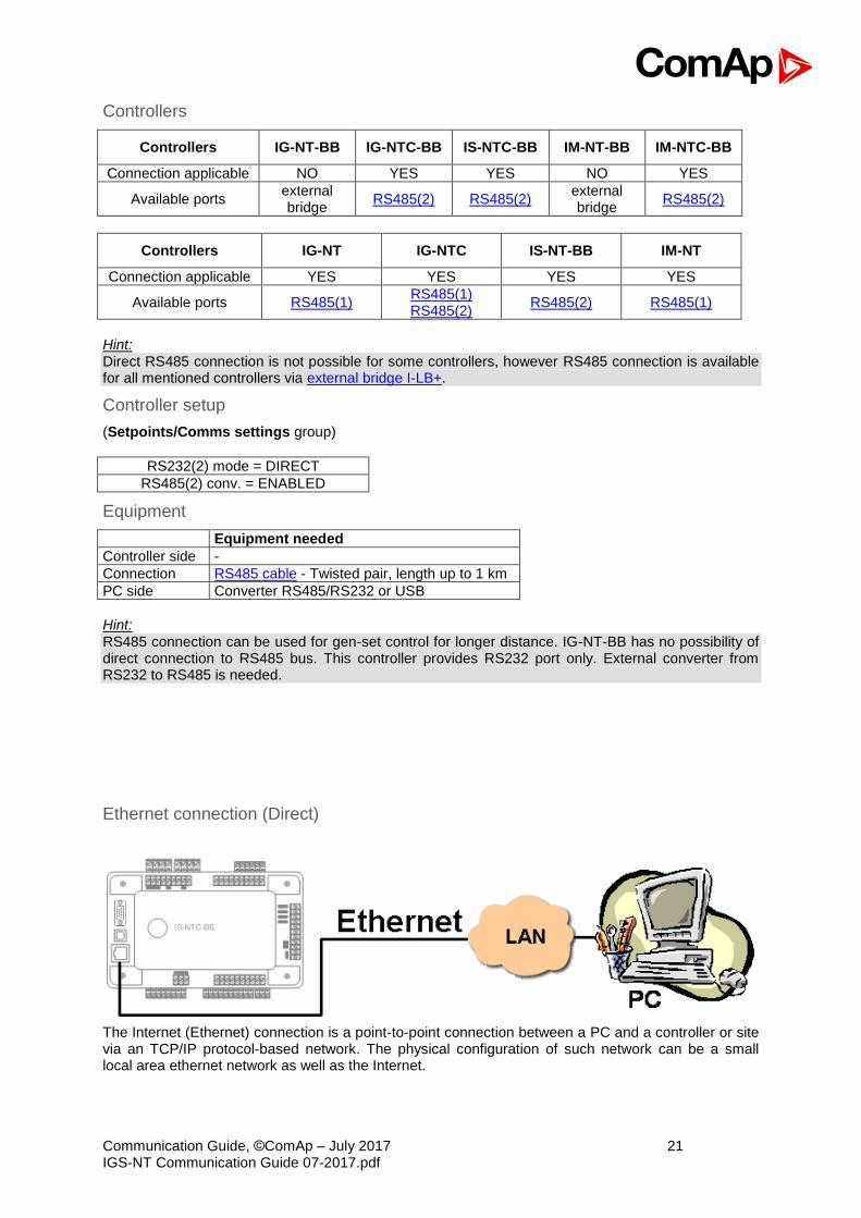
Controllers
Controllers IG-NT-BB IG-NTC-BB IS-NTC-BB IM-NT-BB IM-NTC-BB
Connection applicable NO YES YES NO YES
Available ports external bridge
RS485(2) RS485(2) external bridge
RS485(2)
Controllers IG-NT IG-NTC IS-NT-BB IM-NT
Connection applicable YES YES YES YES
Available ports RS485(1) RS485(1) RS485(2)
RS485(2) RS485(1)
Hint: Direct RS485 connection is not possible for some controllers, however RS485 connection is available for all mentioned controllers via external bridge I-LB+.
Controller setup
(Setpoints/Comms settings group)
RS232(2) mode = DIRECT
RS485(2) conv. = ENABLED
Equipment
Equipment needed
Controller side -
Connection RS485 cable - Twisted pair, length up to 1 km
PC side Converter RS485/RS232 or USB
Hint: RS485 connection can be used for gen-set control for longer distance. IG-NT-BB has no possibility of direct connection to RS485 bus. This controller provides RS232 port only. External converter from RS232 to RS485 is needed.
Ethernet connection (Direct)
The Internet (Ethernet) connection is a point-to-point connection between a PC and a controller or site via an TCP/IP protocol-based network. The physical configuration of such network can be a small local area ethernet network as well as the Internet.
Communication Guide, ©ComAp – July 2017 22 IGS-NT Communication Guide 07-2017.pdf
Controllers
Controllers IG-NT-BB IG-NTC-BB IS-NTC-BB IM-NT-BB IM-NTC-BB
Connection applicable NO YES YES NO YES
Available ports or modules external bridge
ETHERNET ETHERNET external bridge
ETHERNET
Controllers IG-NT IG-NTC IS-NT-BB IM-NT
Connection applicable NO NO NO NO
Available ports or modules external bridge external bridge external bridge external bridge
Hint: Ethernet connection is available for all mentioned controllers via external bridge or IB-NT (see the chapter Ethernet connection via IB-NT).
Number of clients connected simultaneously
2 clients with InteliMonitor or WebSupervisor (Comap/TCP protocol) 2 clients with web interface
Using a web browser
Ethernet connection to controller makes possible using any web browser for basic monitoring and adjustment of the controller. Simply put the IP address of the module into the address line in your web
browser like http://192.168.1.254 and then enter access code. In case of connection from web
browser there is 5 minutes timeout after closing the browser window. After that the client is automatically logged out.
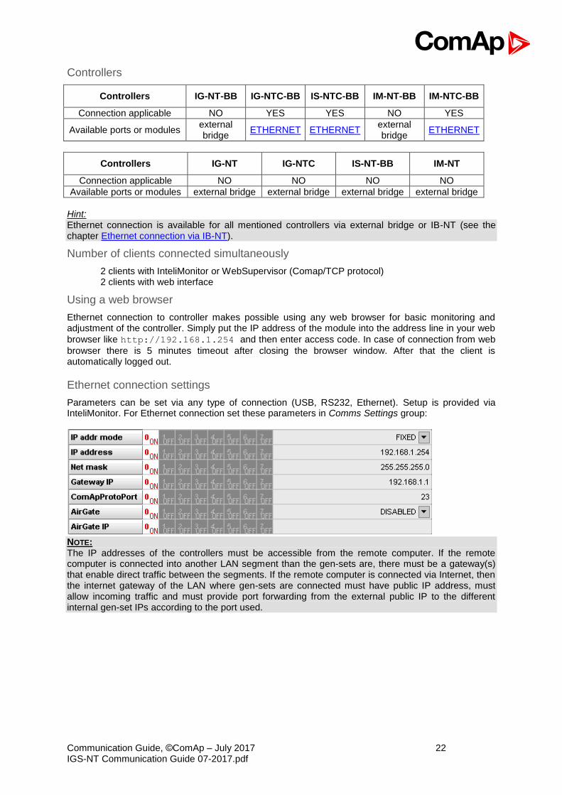
Ethernet connection settings
Parameters can be set via any type of connection (USB, RS232, Ethernet). Setup is provided via InteliMonitor. For Ethernet connection set these parameters in Comms Settings group:
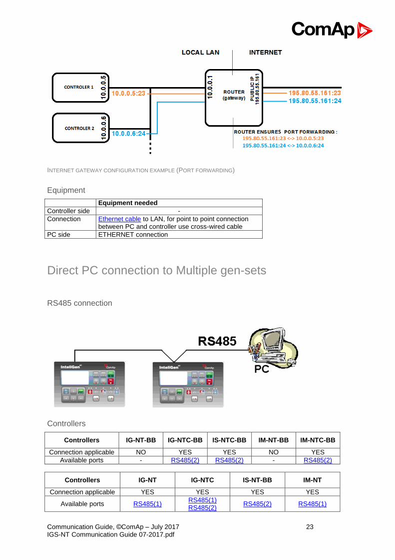
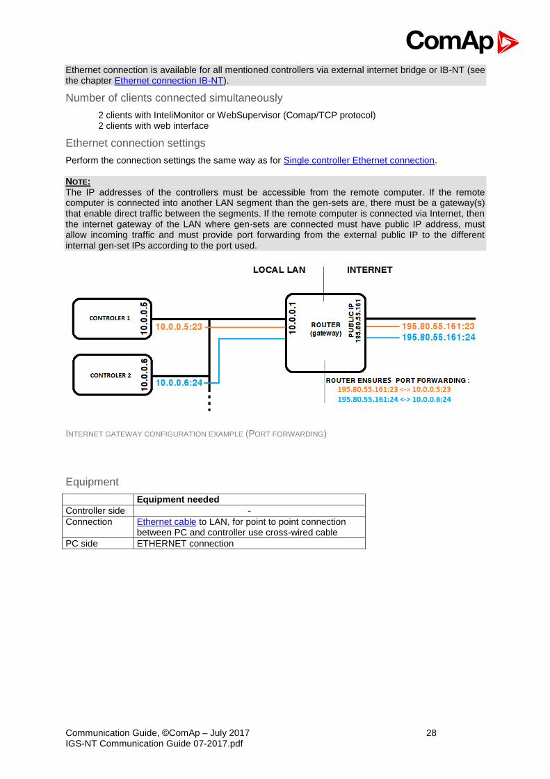
NOTE: The IP addresses of the controllers must be accessible from the remote computer. If the remote computer is connected into another LAN segment than the gen-sets are, there must be a gateway(s) that enable direct traffic between the segments. If the remote computer is connected via Internet, then the internet gateway of the LAN where gen-sets are connected must have public IP address, must allow incoming traffic and must provide port forwarding from the external public IP to the different internal gen-set IPs according to the port used.
Communication Guide, ©ComAp – July 2017 23 IGS-NT Communication Guide 07-2017.pdf
INTERNET GATEWAY CONFIGURATION EXAMPLE (PORT FORWARDING)
Equipment
Equipment needed
Controller side -
Connection Ethernet cable to LAN, for point to point connection between PC and controller use cross-wired cable
PC side ETHERNET connection
Direct PC connection to Multiple gen-sets
RS485 connection
Controllers
Controllers IG-NT-BB IG-NTC-BB IS-NTC-BB IM-NT-BB IM-NTC-BB
Connection applicable NO YES YES NO YES
Available ports - RS485(2) RS485(2) - RS485(2)
Controllers IG-NT IG-NTC IS-NT-BB IM-NT
Connection applicable YES YES YES YES
Available ports RS485(1) RS485(1) RS485(2)
RS485(2) RS485(1)
Communication Guide, ©ComAp – July 2017 24 IGS-NT Communication Guide 07-2017.pdf
Controller setup
(Setpoints/Comms settings group)
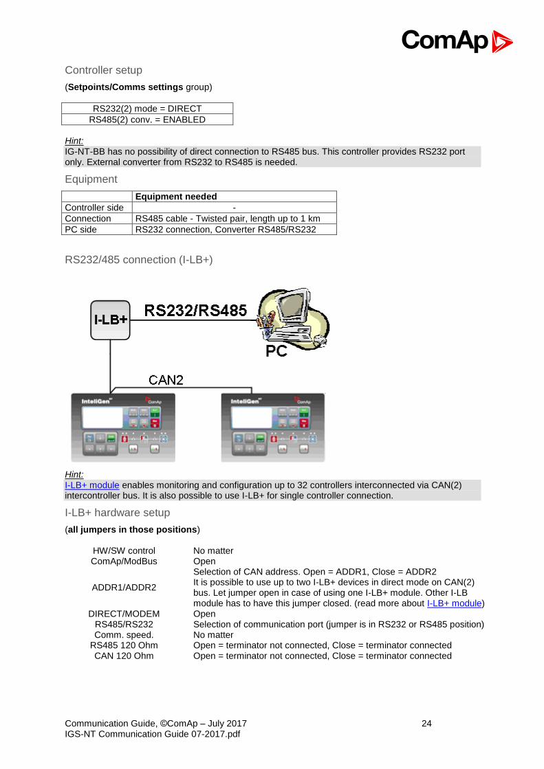
RS232(2) mode = DIRECT
RS485(2) conv. = ENABLED
Hint: IG-NT-BB has no possibility of direct connection to RS485 bus. This controller provides RS232 port only. External converter from RS232 to RS485 is needed.
Equipment
Equipment needed
Controller side -
Connection RS485 cable - Twisted pair, length up to 1 km
PC side RS232 connection, Converter RS485/RS232
RS232/485 connection (I-LB+)
Hint: I-LB+ module enables monitoring and configuration up to 32 controllers interconnected via CAN(2) intercontroller bus. It is also possible to use I-LB+ for single controller connection.
I-LB+ hardware setup
(all jumpers in those positions)
HW/SW control No matter ComAp/ModBus Open
ADDR1/ADDR2
Selection of CAN address. Open = ADDR1, Close = ADDR2 It is possible to use up to two I-LB+ devices in direct mode on CAN(2) bus. Let jumper open in case of using one I-LB+ module. Other I-LB module has to have this jumper closed. (read more about I-LB+ module)
DIRECT/MODEM Open RS485/RS232 Selection of communication port (jumper is in RS232 or RS485 position) Comm. speed. No matter
RS485 120 Ohm Open = terminator not connected, Close = terminator connected CAN 120 Ohm Open = terminator not connected, Close = terminator connected

Communication Guide, ©ComAp – July 2017 25 IGS-NT Communication Guide 07-2017.pdf
Controllers
Controllers IG-NT-BB IG-NTC-BB IS-NTC-BB IM-NT-BB IM-NTC-BB
Connection applicable YES YES YES YES YES
Available ports
RS232 on I-LB+
RS485 on I-LB+
RS232 on I-LB+
RS485 on I-LB+
RS232 on I-LB+
RS485 on I-LB+
RS232 on I-LB+
RS485 on I-LB+
RS232 on I-LB+
RS485 on I-LB+
Controllers IG-NT IG-NTC IS-NT-BB IM-NT
Connection applicable YES YES YES YES
Available ports RS232 on I-LB+ RS485 on I-LB+
RS232 on I-LB+ RS485 on I-LB+
RS232 on I-LB+ RS485 on I-LB+
RS232 on I-LB+ RS485 on I-LB+
Equipment
Equipment needed
Controller side I-LB+ unit
Connection RS232 or RS485 cable
PC side RS232 connection or RS232/USB converter RS485 connection or RS485/USB converter
USB connection via I-LB+ module
Hint:
I-LB+ module enables monitoring and configuration up to 32 controllers interconnected via CAN(2) intercontroller bus. It is also possible to use I-LB+ for single controller connection.
I-LB+ hardware setup
(all jumpers in those positions)
HW/SW control no matter (Open) ComAp/ModBus Open ADDR1/ADDR2 Selection of CAN address. Open = ADDR2, Close = ADDR1
Communication Guide, ©ComAp – July 2017 26 IGS-NT Communication Guide 07-2017.pdf
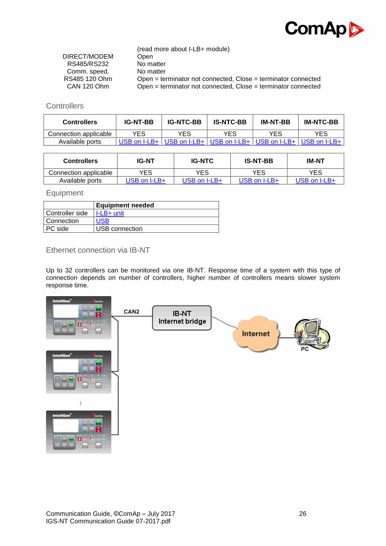
(read more about I-LB+ module) DIRECT/MODEM Open
RS485/RS232 No matter Comm. speed. No matter
RS485 120 Ohm Open = terminator not connected, Close = terminator connected CAN 120 Ohm Open = terminator not connected, Close = terminator connected
Controllers
Controllers IG-NT-BB IG-NTC-BB IS-NTC-BB IM-NT-BB IM-NTC-BB
Connection applicable YES YES YES YES YES
Available ports USB on I-LB+ USB on I-LB+ USB on I-LB+ USB on I-LB+ USB on I-LB+
Controllers IG-NT IG-NTC IS-NT-BB IM-NT
Connection applicable YES YES YES YES
Available ports USB on I-LB+ USB on I-LB+ USB on I-LB+ USB on I-LB+
Equipment
Equipment needed
Controller side I-LB+ unit
Connection USB
PC side USB connection
Ethernet connection via IB-NT
Up to 32 controllers can be monitored via one IB-NT. Response time of a system with this type of connection depends on number of controllers, higher number of controllers means slower system response time.

Communication Guide, ©ComAp – July 2017 27 IGS-NT Communication Guide 07-2017.pdf
Controllers
Controllers IG-NT-BB IG-NTC-BB IS-NTC-BB IM-NT-BB IM-NTC-BB
Connection applicable YES YES YES YES YES
Available ports / modules IB-NT IB-NT IB-NT IB-NT IB-NT
Controllers IG-NT IG-NTC IS-NT-BB IM-NT
Connection applicable YES YES YES YES
Available ports / modules IB-NT IB-NT IB-NT IB-NT
NOTE: Max. 3 clients of ComAp type (InteliDDE server, WinScope, WebSupervisor) can be connected simultaneously to the IB-NT. Hint: For more information about IB-NT internet bridge read IB-NT-2.0-Reference Guide.pdf.
Ethernet connection (Direct)
Controllers
Controllers IG-NT-BB IG-NTC-BB IS-NTC-BB IM-NT-BB IM-NTC-BB
Connection applicable NO YES YES NO YES
Available ports external bridge
ETHERNET ETHERNET external bridge
ETHERNET
Controllers IG-NT IG-NTC IS-NT-BB IM-NT
Connection applicable NO NO NO NO
Available ports external bridge external bridge external bridge external bridge
Hint:
Communication Guide, ©ComAp – July 2017 28 IGS-NT Communication Guide 07-2017.pdf
Ethernet connection is available for all mentioned controllers via external internet bridge or IB-NT (see the chapter Ethernet connection IB-NT).
Number of clients connected simultaneously
2 clients with InteliMonitor or WebSupervisor (Comap/TCP protocol) 2 clients with web interface
Ethernet connection settings
Perform the connection settings the same way as for Single controller Ethernet connection. NOTE: The IP addresses of the controllers must be accessible from the remote computer. If the remote computer is connected into another LAN segment than the gen-sets are, there must be a gateway(s) that enable direct traffic between the segments. If the remote computer is connected via Internet, then the internet gateway of the LAN where gen-sets are connected must have public IP address, must allow incoming traffic and must provide port forwarding from the external public IP to the different internal gen-set IPs according to the port used.
INTERNET GATEWAY CONFIGURATION EXAMPLE (PORT FORWARDING)
Equipment
Equipment needed
Controller side -
Connection Ethernet cable to LAN, for point to point connection between PC and controller use cross-wired cable
PC side ETHERNET connection
Communication Guide, ©ComAp – July 2017 29 IGS-NT Communication Guide 07-2017.pdf
Monitoring Local on site - MODBUS
ModBus - Single gen-set
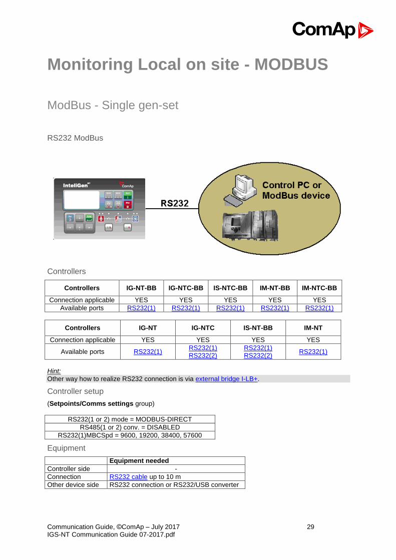
RS232 ModBus
Controllers
Controllers IG-NT-BB IG-NTC-BB IS-NTC-BB IM-NT-BB IM-NTC-BB
Connection applicable YES YES YES YES YES
Available ports RS232(1) RS232(1) RS232(1) RS232(1) RS232(1)
Controllers IG-NT IG-NTC IS-NT-BB IM-NT
Connection applicable YES YES YES YES
Available ports RS232(1) RS232(1) RS232(2)
RS232(1) RS232(2)
RS232(1)
Hint: Other way how to realize RS232 connection is via external bridge I-LB+.
Controller setup
(Setpoints/Comms settings group)
RS232(1 or 2) mode = MODBUS-DIRECT
RS485(1 or 2) conv. = DISABLED
RS232(1)MBCSpd = 9600, 19200, 38400, 57600
Equipment
Equipment needed
Controller side -
Connection RS232 cable up to 10 m
Other device side RS232 connection or RS232/USB converter
Communication Guide, ©ComAp – July 2017 30 IGS-NT Communication Guide 07-2017.pdf
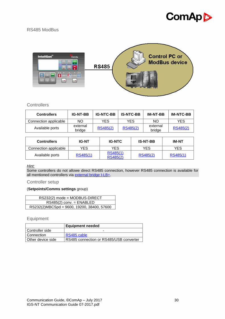
RS485 ModBus
Controllers
Controllers IG-NT-BB IG-NTC-BB IS-NTC-BB IM-NT-BB IM-NTC-BB
Connection applicable NO YES YES NO YES
Available ports external bridge
RS485(2) RS485(2) external bridge
RS485(2)
Controllers IG-NT IG-NTC IS-NT-BB IM-NT
Connection applicable YES YES YES YES
Available ports RS485(1) RS485(1) RS485(2)
RS485(2) RS485(1)
Hint: Some controllers do not allowe direct RS485 connection, however RS485 connection is available for all mentioned controllers via external bridge I-LB+.
Controller setup
(Setpoints/Comms settings group)
RS232(2) mode = MODBUS-DIRECT
RS485(2) conv. = ENABLED
RS232(2)MBCSpd = 9600, 19200, 38400, 57600
Equipment
Equipment needed
Controller side -
Connection RS485 cable
Other device side RS485 connection or RS485/USB converter
Communication Guide, ©ComAp – July 2017 31 IGS-NT Communication Guide 07-2017.pdf
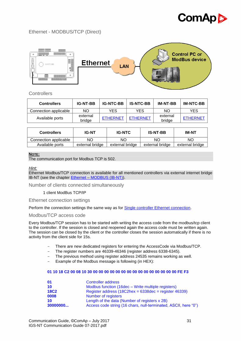
Ethernet - MODBUS/TCP (Direct)
Controllers
Controllers IG-NT-BB IG-NTC-BB IS-NTC-BB IM-NT-BB IM-NTC-BB
Connection applicable NO YES YES NO YES
Available ports external bridge
ETHERNET ETHERNET external bridge
ETHERNET
Controllers IG-NT IG-NTC IS-NT-BB IM-NT
Connection applicable NO NO NO NO
Available ports external bridge external bridge external bridge external bridge
NOTE: The communication port for Modbus TCP is 502. Hint: Ethernet Modbus/TCP connection is available for all mentioned controllers via external internet bridge IB-NT (see the chapter Ethernet – MODBUS (IB-NT)).
Number of clients connected simultaneously
1 client ModBus TCP/IP
Ethernet connection settings
Perform the connection settings the same way as for Single controller Ethernet connection.
Modbus/TCP access code
Every Modbus/TCP session has to be started with writing the access code from the modbus/tcp client to the controller. If the session is closed and reopened again the access code must be written again. The session can be closed by the client or the controller closes the session automatically if there is no activity from the client side for 15s.
- There are new dedicated registers for entering the AccessCode via Modbus/TCP.
- The register numbers are 46339-46346 (register address 6338-6345).
- The previous method using register address 24535 remains working as well.
- Example of the Modbus message is following (in HEX):
01 10 18 C2 00 08 10 30 00 00 00 00 00 00 00 00 00 00 00 00 00 00 00 FE F3
01 Controller address 10 Modbus function (16dec – Write multiple registers) 18C2 Register address (18C2hex = 6338dec = register 46339) 0008 Number of registers 10 Length of the data (Number of registers x 2B) 30000000... Access code string (16 chars, null-terminated, ASCII, here “0”)
Communication Guide, ©ComAp – July 2017 32 IGS-NT Communication Guide 07-2017.pdf
FEF3 CRC
Some devices do not support the modbus function 16. In this case can be the access code writen in controller as one register No. 46339 using the function 6. The access code has to be the number in the range 0 to 65535.
Equipment
Equipment needed
Controller side -
Connection Ethernet cable to LAN, for point to point connection between PC and controller use cross-wired cable
PC side ETHERNET connection
For more informations about ModBus implementation to ComAp controllers read the chapter ModBus communication.
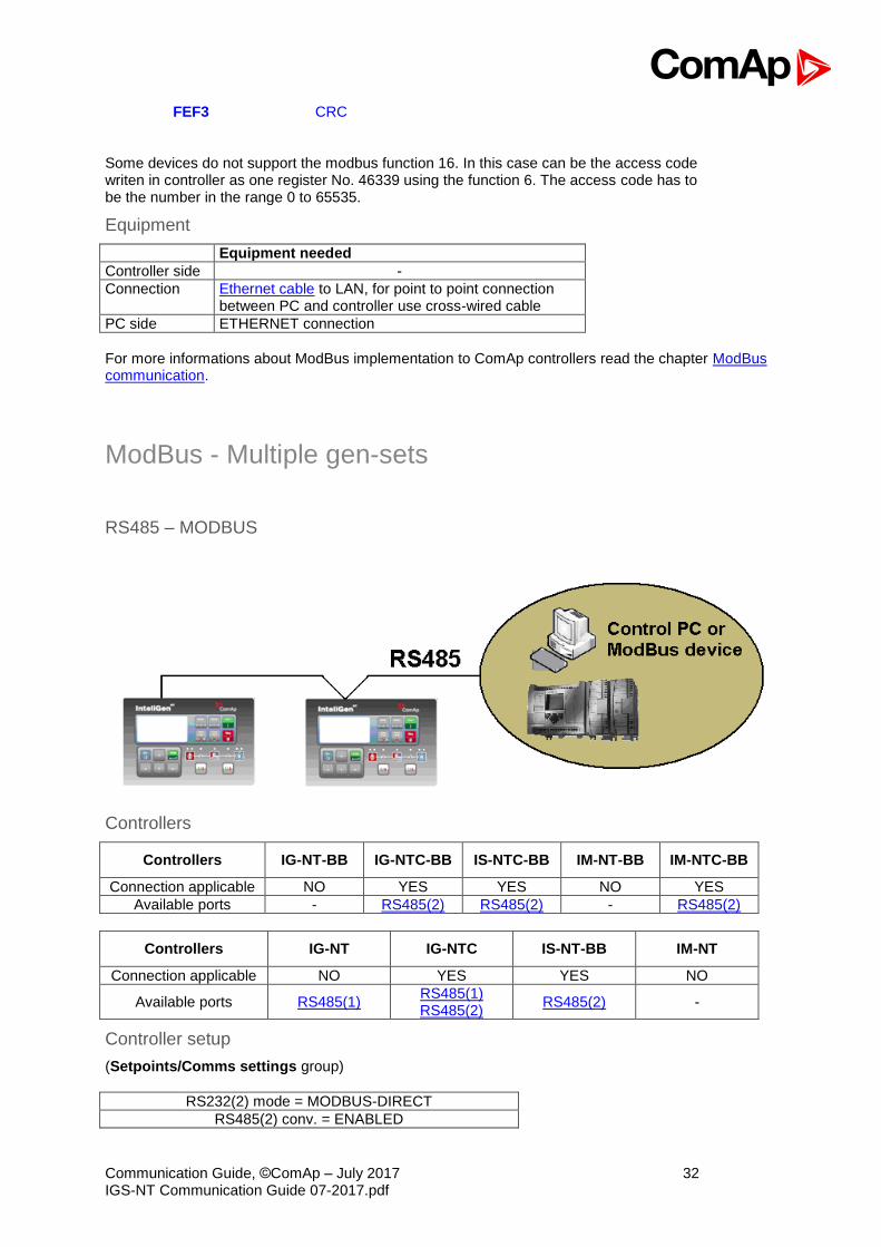
ModBus - Multiple gen-sets
RS485 – MODBUS
Controllers
Controllers IG-NT-BB IG-NTC-BB IS-NTC-BB IM-NT-BB IM-NTC-BB
Connection applicable NO YES YES NO YES
Available ports - RS485(2) RS485(2) - RS485(2)
Controllers IG-NT IG-NTC IS-NT-BB IM-NT
Connection applicable NO YES YES NO
Available ports RS485(1) RS485(1) RS485(2)
RS485(2) -
Controller setup
(Setpoints/Comms settings group)
RS232(2) mode = MODBUS-DIRECT
RS485(2) conv. = ENABLED

Communication Guide, ©ComAp – July 2017 33 IGS-NT Communication Guide 07-2017.pdf
RS232(2)MBCSpd = 9600, 19200, 38400, 57600
Hint: For gen-set control for longer distance can be RS485 used. IG-NT-BB has no possibility of direct connection to RS485 bus. This controller provides RS232 port only. External converter from RS232 to RS485 may be a good solution (for example...ADAM).
Equipment
Equipment needed
Controller side -
Connection RS485 cable - Twisted pair, length up to 1 km
Other device side RS485 connection or RS485/RS232 or USB converter
RS232/RS485 – MODBUS (I-LB+)
Hint: I-LB+ module enables monitoring and configuration up to 32 controllers interconnected via CAN(2) intercontroller bus. It is also possible to use I-LB+ for single controller connection.
I-LB+ hardware setup
(all jumpers in those positions)
HW/SW control No matter ComAp/ModBus Close
ADDR1/ADDR2
Selection of CAN address. Open = ADDR1, Close = ADDR2 It is possible to use up to two I-LB+ devices in direct mode on CAN(2) bus. Let jumper open in case of using one I-LB+ module. Other I-LB module has to have this jumper closed. (read more about I-LB+ module)
DIRECT/MODEM No matter RS485/RS232 Selection of communication port (jumper is in RS232 or RS485 position)
Comm. speed. Selection of communication speed by jumpers P13, P14 to 9600, 19200, 38400, 57600 bps
RS485 120 Ohm Open = terminator not connected, Close = terminator connected CAN 120 Ohm Open = terminator not connected, Close = terminator connected
Controllers
Controllers IG-NT-BB IG-NTC-BB IS-NTC-BB IM-NT-BB IM-NTC-BB
Connection applicable
YES YES YES YES YES
Available RS232 on I-LB+ RS232 on I-LB+ RS232 on I-LB+ RS232 on I-LB+ RS232 on I-LB+

Communication Guide, ©ComAp – July 2017 34 IGS-NT Communication Guide 07-2017.pdf
ports RS485 on I-LB+ RS485 on I-LB+ RS485 on I-LB+ RS485 on I-LB+ RS485 on I-LB+
Controllers IG-NT IG-NTC IS-NT-BB IM-NT
Connection applicable NO YES YES NO
Available ports RS232 on I-LB+ RS485 on I-LB+
RS232 on I-LB+ RS485 on I-LB+
RS232 on I-LB+ RS485 on I-LB+
RS232 on I-LB+ RS485 on I-LB+
Equipment
Equipment needed
Controller side I-LB+ unit
Connection RS232, RS485 cable
PC side RS232 connection or RS232/USB converter RS485 connection or RS485/USB converter
Ethernet - MODBUS (IB-NT)
Up to 32 controllers can be monitored via one IB-NT. Response time of a system with this type of connection depends on number of controllers, higher number of controllers means slower system response time.
Controllers
Controllers IG-NT-BB IG-NTC-BB IS-NTC-BB IM-NT-BB IM-NTC-BB
Connection applicable YES YES YES YES YES
Available ports / modules external
bridge IB-NT external
bridge IB-NT external
bridge IB-NT external
bridge IB-NT external
bridge IB-NT
Controllers IG-NT IG-NTC IS-NT-BB IM-NT
Connection applicable YES YES YES YES
Available ports / modules external bridge
IB-NT external bridge
IB-NT external bridge
IB-NT external bridge
IB-NT
Hint:
Communication Guide, ©ComAp – July 2017 35 IGS-NT Communication Guide 07-2017.pdf
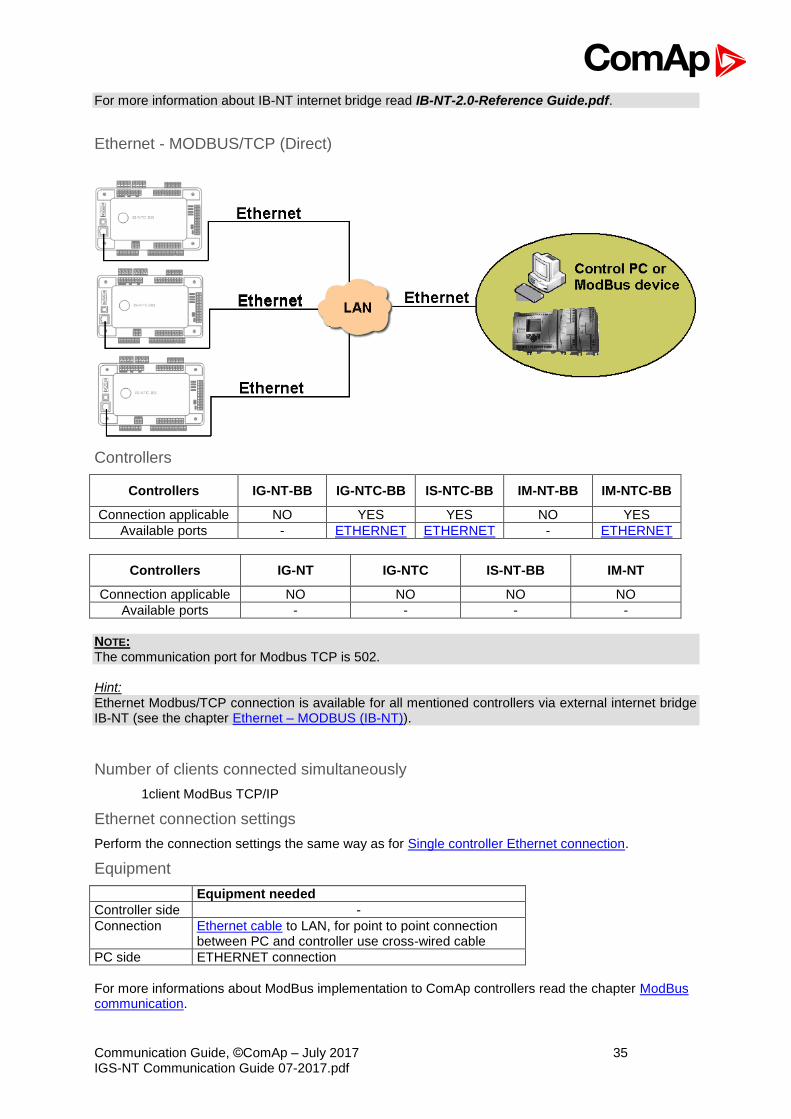
For more information about IB-NT internet bridge read IB-NT-2.0-Reference Guide.pdf.
Ethernet - MODBUS/TCP (Direct)
Controllers
Controllers IG-NT-BB IG-NTC-BB IS-NTC-BB IM-NT-BB IM-NTC-BB
Connection applicable NO YES YES NO YES
Available ports - ETHERNET ETHERNET - ETHERNET
Controllers IG-NT IG-NTC IS-NT-BB IM-NT
Connection applicable NO NO NO NO
Available ports - - - -
NOTE: The communication port for Modbus TCP is 502. Hint: Ethernet Modbus/TCP connection is available for all mentioned controllers via external internet bridge IB-NT (see the chapter Ethernet – MODBUS (IB-NT)).
Number of clients connected simultaneously
1client ModBus TCP/IP
Ethernet connection settings
Perform the connection settings the same way as for Single controller Ethernet connection.
Equipment
Equipment needed
Controller side -
Connection Ethernet cable to LAN, for point to point connection between PC and controller use cross-wired cable
PC side ETHERNET connection
For more informations about ModBus implementation to ComAp controllers read the chapter ModBus communication.

Communication Guide, ©ComAp – July 2017 36 IGS-NT Communication Guide 07-2017.pdf
Remote monitoring
Connection to Internet (Direct)
Controllers
Controllers IG-NT-BB IG-NTC-BB IS-NTC-BB IM-NT-BB IM-NTC-BB
Connection applicable NO YES YES NO YES
Available ports external bridge
ETHERNET ETHERNET external bridge
ETHERNET
Controllers IG-NT IG-NTC IS-NT-BB IM-NT
Connection applicable NO NO NO NO
Available ports external bridge external bridge external bridge external bridge
Hint:
Internet connection is available for all mentioned controllers via external bridge or IB-NT (see the chapter Ethernet connection via IB-NT).
Number of clients connected simultaneously
2 clients with InteliMonitor or WebSupervisor (Comap/TCP protocol) 1 client Modbus/TCP 2 clients with web interface

Communication Guide, ©ComAp – July 2017 37 IGS-NT Communication Guide 07-2017.pdf
Ethernet connection settings
Perform the connection settings the same way as for Single controller Ethernet connection.
How to open Internet connection in InteliMonitor?
Use the same procedure as well as for Multiple gen-sets Ethernet connection.
Using a web browser
Ethernet connection to controller makes possible using any web browser for basic monitoring and adjustment of the controller. Simply put the IP address of the module into the address line in your web
browser like http://192.168.1.254 and then enter access code. In case of connection from web
browser there is 5 minutes timeout after closing the browser window. After that the client is automatically logged out.
NOTE: The IP addresses of the controllers must be accessible from the remote computer. If the remote computer is connected into another LAN segment than the gen-sets are, there must be a gateway(s) that enable direct traffic between the segments. If the remote computer is connected via Internet, then the internet gateway of the LAN where gen-sets are connected must have public IP address, must allow incoming traffic and must provide port forwarding from the external public IP to the different internal gen-set IPs according to the port used.
INTERNET GATEWAY CONFIGURATION EXAMPLE (PORT FORWARDING)
Equipment
Equipment needed
Controller side -
Connection Ethernet cable to LAN, for point to point connection between PC and controller use cross-wired cable
PC side ETHERNET connection
Available software for IG/IS-NT
Software GenConfig InteliMonitor WinScope
Applicable YES YES YES
Communication Guide, ©ComAp – July 2017 38 IGS-NT Communication Guide 07-2017.pdf
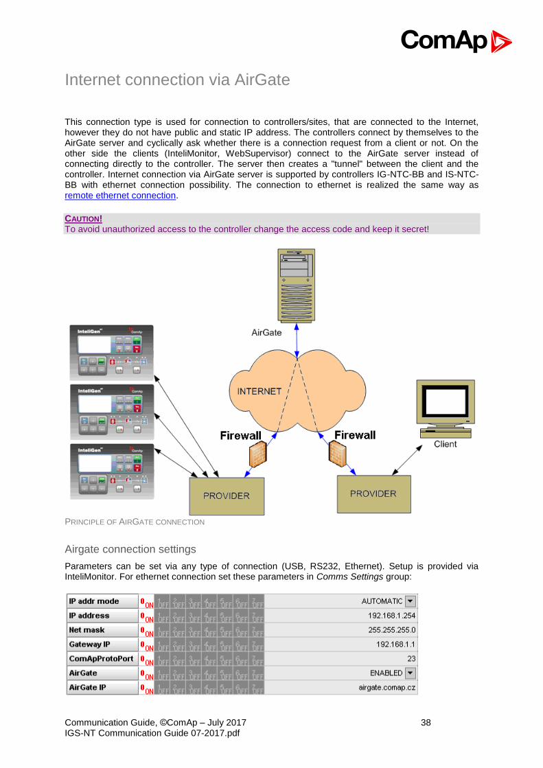
Internet connection via AirGate
This connection type is used for connection to controllers/sites, that are connected to the Internet, however they do not have public and static IP address. The controllers connect by themselves to the AirGate server and cyclically ask whether there is a connection request from a client or not. On the other side the clients (InteliMonitor, WebSupervisor) connect to the AirGate server instead of connecting directly to the controller. The server then creates a "tunnel" between the client and the controller. Internet connection via AirGate server is supported by controllers IG-NTC-BB and IS-NTC-BB with ethernet connection possibility. The connection to ethernet is realized the same way as remote ethernet connection.
CAUTION! To avoid unauthorized access to the controller change the access code and keep it secret!
PRINCIPLE OF AIRGATE CONNECTION
Airgate connection settings
Parameters can be set via any type of connection (USB, RS232, Ethernet). Setup is provided via InteliMonitor. For ethernet connection set these parameters in Comms Settings group:

Communication Guide, ©ComAp – July 2017 39 IGS-NT Communication Guide 07-2017.pdf
Controllers
Controllers IG-NT-BB IG-NTC-BB IS-NTC-BB IM-NT-BB IM-NTC-BB
Connection applicable NO YES YES NO YES
Available ports external
bridge IB-NT ETHERNET ETHERNET
external bridge IB-NT
ETHERNET
Controllers IG-NT IG-NTC IS-NT-BB IM-NT
Connection applicable NO NO NO NO
Available ports external bridge
IB-NT external bridge
IB-NT external bridge
IB-NT external bridge
IB-NT
CAUTION! Connection via AirGate is supported by controllers with direct connection to LAN only or via IB-NT module.
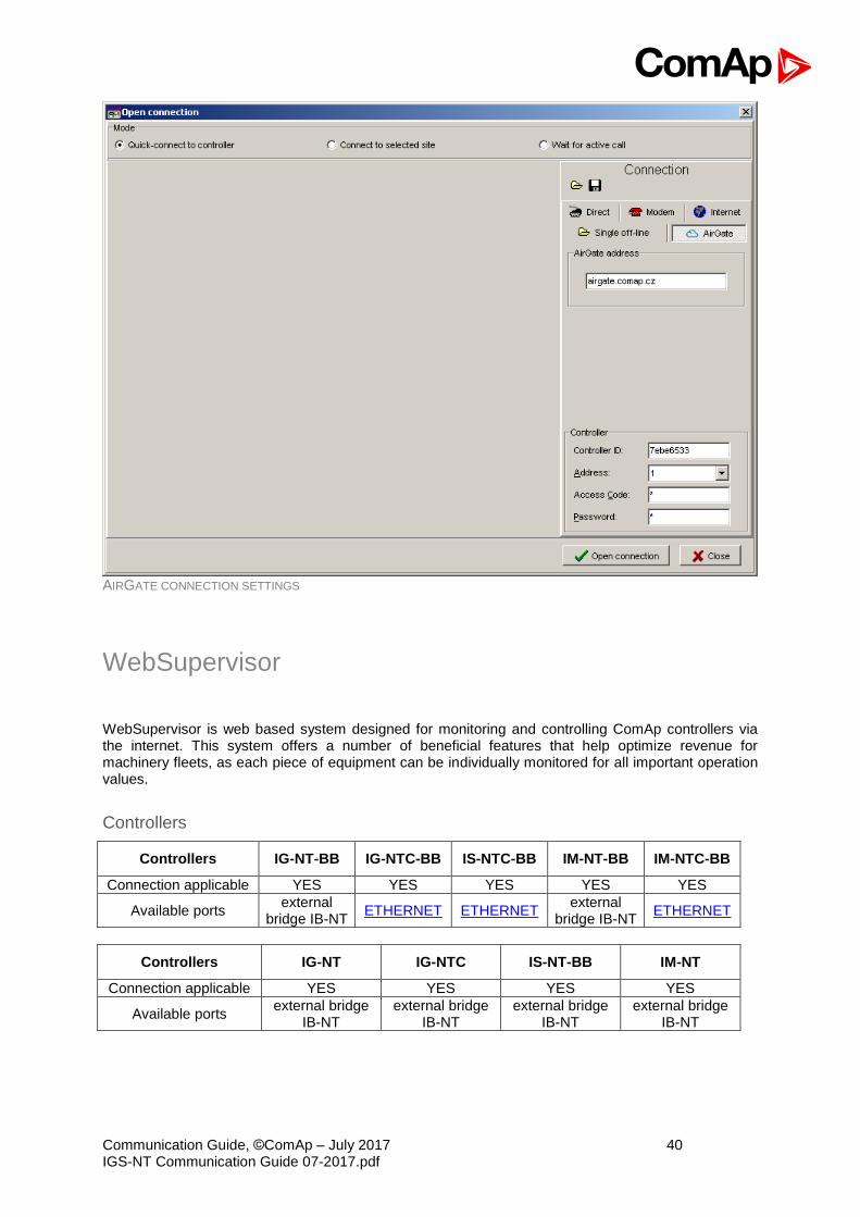
Connection to InteliMonitor via AirGate server
1. Select the AirGate connection type. 2. Fill-in the correct AirGate ID for each controller. 3. Enter the AirGate server address.
Hint: You will obtain the AirGate ID by the registration of the particular controller on the AirGate server. Set all setpoints in Comms Settings group according to AirGate connecgtion settings and connect controller to LAN. Controller AirGate ID will be viewed on the screen. NOTE: This function is available in InteliMonitor ver. 2.6 and higher. Please watch the ComAp web site for detailed information. NOTE: Although the controllers in your site are not connected together by the CAN2 bus they must have different controller addresses.
Communication Guide, ©ComAp – July 2017 40 IGS-NT Communication Guide 07-2017.pdf
AIRGATE CONNECTION SETTINGS
WebSupervisor
WebSupervisor is web based system designed for monitoring and controlling ComAp controllers via the internet. This system offers a number of beneficial features that help optimize revenue for machinery fleets, as each piece of equipment can be individually monitored for all important operation values.
Controllers
Controllers IG-NT-BB IG-NTC-BB IS-NTC-BB IM-NT-BB IM-NTC-BB
Connection applicable YES YES YES YES YES
Available ports external
bridge IB-NT ETHERNET ETHERNET
external bridge IB-NT
ETHERNET
Controllers IG-NT IG-NTC IS-NT-BB IM-NT
Connection applicable YES YES YES YES
Available ports external bridge
IB-NT external bridge
IB-NT external bridge
IB-NT external bridge
IB-NT
Communication Guide, ©ComAp – July 2017 41 IGS-NT Communication Guide 07-2017.pdf
WebSupervisor connection settings
Connection of controllers with direct Ethernet port can be realized two diferent ways: 1. Internet connection via AirGate: No fixed and public IP address is needed. Connect
and set the controller the same way as for Internet connection via AirGate. 2. Internet connection without AirgGate: Controller has to have fixed and public IP
address. Connect and set the controller the same way as for Ethernet Connection (Direct).
Connection of all controllers can be realized using IB-NT external bridge.
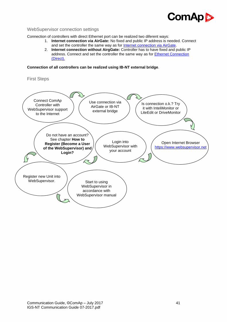
First Steps
Connect ComAp Controller with
WebSupervisor support to the Internet
Use connection via AirGate or IB-NT external bridge
Is connection o.k.? Try it with InteliMonitor or
LiteEdit or DriveMonitor
Open Internet Browser
https://www.websupervisor.net
Login into WebSupervisor with
your account
Do not have an account?
See chapter How to Register (Become a User
of the WebSupervisor) and Login?
Register new Unit into WebSupervisor. Start to using
WebSupervisor in accordance with
WebSupervisor manual

Communication Guide, ©ComAp – July 2017 42 IGS-NT Communication Guide 07-2017.pdf
Start to using
How to Register (Become a User of the WebSupervisor) and Login? You can start using WebSupervisor without installation any special software on your PC. To start and login into WebSupervisor open https://www.websupervisor.net in your browser and follow the steps at WebSupervisor.
More information about WebSupervisor you can get at https://www.websupervisor.net/download/WebSupervisor 4.0 - Global Guide.pdf
Web interface
The web interface is intended to monitor the controller from a web browser. Static IP address is required for this function as you must know the IP address to put it into the browser. Public IP address or port forwarding is required if you want to see the web pages from the Internet.
PORT FORWARDING EXAMPLE FOR WEB CONNECTION

Communication Guide, ©ComAp – July 2017 43 IGS-NT Communication Guide 07-2017.pdf
The web server is designed for basic monitoring and adjustment of the controller using a web browser. Put the Controller IP address into the browser. You will be asked for the controller access code prior to entering the controller web.
NOTE: The web server is optimized for IE6 or higher and screen resolution 1024x768 pixels. NOTE: For update inbuilt Ethernet module see IB-COM manual. Or add suffix to IP address “/sp_index.htm” and follow instructions, eg: “192.168.1.1/sp_index.htm”. CAUTION! Do not use the browser navigation buttons as "Back", "Forward" or "Reload". Use the links and the reload button located in the toolbar instead.
Scada
Click to the SCADA link in the toolbar to display the scada page. The scada page is also the main page which is displayed by default if you just put the controller address into the browser.
NOTE: The scada page layout may differ according to the firmware branch, version and application. Certain old firmware versions does not support web access at all.
Measurement
Click to the MEASUREMENT link in the toolbar to display the measurement page. Then click to the required group name in the left box to display values of the group in the right box.
NOTE: The measurement page is automatically refreshed every 60 seconds.

Communication Guide, ©ComAp – July 2017 44 IGS-NT Communication Guide 07-2017.pdf
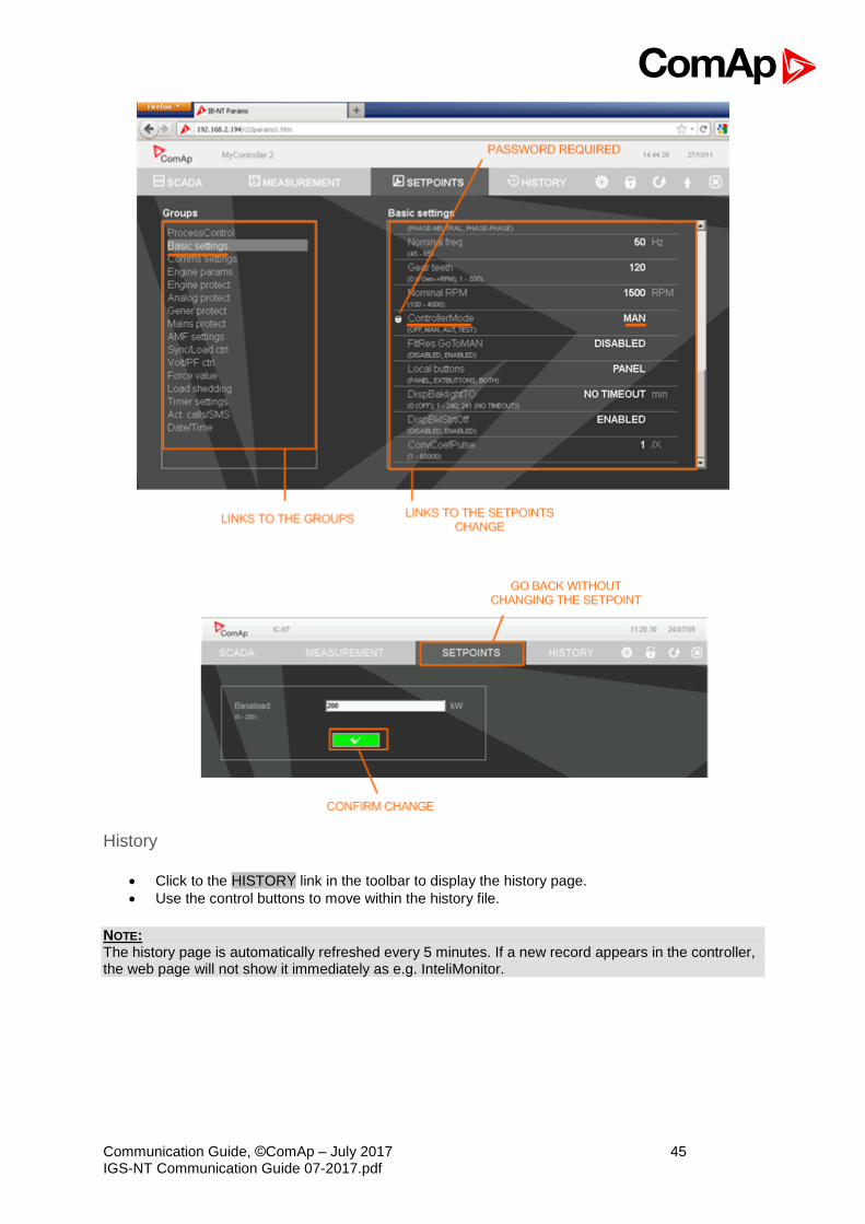
Setpoints
• Click to the SETPOINTS link in the toolbar to display the setpoints page.
• Click to the required group name in the left box to display setpoints of the group in the right box.
• Click to the required setpoint name or value to change the value. If the respective setpoint is protected by password, which is indicated by a lock icon by the setpoint name, you have to click on the "Controller password" icon located in the toolbar and then enter valid password.
NOTE: The setpoint page is automatically refreshed every 60 seconds. If an another user changes a setpoint from other terminal, the web page will not show this change immediately as e.g. InteliMonitor.
Communication Guide, ©ComAp – July 2017 45 IGS-NT Communication Guide 07-2017.pdf
History
• Click to the HISTORY link in the toolbar to display the history page.
• Use the control buttons to move within the history file.
NOTE: The history page is automatically refreshed every 5 minutes. If a new record appears in the controller, the web page will not show it immediately as e.g. InteliMonitor.

Communication Guide, ©ComAp – July 2017 46 IGS-NT Communication Guide 07-2017.pdf
Web server adjustment
• Click to the "Webserver settings" icon in the toolbar to display the settings page.
• Select the controller language the web pages will appear in.
• Select the rate of automatic refresh of the scada page.
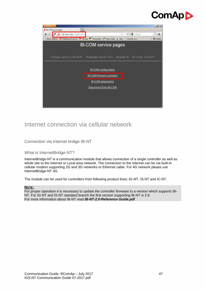
Commnication module firmware upgrade
Firmware in inbuilt communication module (IB-COM) can be upgraded. For upgrade type in wour web browser IP address of controller and behind the address type “/SP_INDEX.HTM”.
For more information please follow manual related to IB-COM. https://www.comap-control.com/support/download-center/documentation/man/ib-com-1-4-1-1-new-features-pdf
Communication Guide, ©ComAp – July 2017 47 IGS-NT Communication Guide 07-2017.pdf
Internet connection via cellular network
Connection via Internet bridge IB-NT
What is InternetBridge-NT?
InternetBridge-NT is a communication module that allows connection of a single controller as well as whole site to the Internet or Local area network. The connection to the Internet can be via built-in cellular modem supporting 2G and 3G networks or Ethernet cable. For 4G network please use InternetBridge-NT 4G.
The module can be used for controllers from following product lines: IG-NT, IS-NT and IC-NT.
NOTE: For proper operation it is necessary to update the controller firmware to a version which supports IB-NT. For IG-NT and IS-NT standard branch the first version supporting IB-NT is 2.6. For more information about IB-NT read IB-NT-2.0-Reference Guide.pdf.
Communication Guide, ©ComAp – July 2017 48 IGS-NT Communication Guide 07-2017.pdf
Features
• Direct ethernet connection to ComAp PC programs
• AirGate® support
• SMTP protocol for sending of active emails from the controller
• HTTP protocol for web-based monitoring and adjustment
• MODBUS/TCP server
• SNMP protocol
Active Call
Function
When active calls are activated for alarms on site (warning, shut-down…) the controller calls to the preselected telephone number and sends the ANT archive file. Software (e.g. InteliMonitor) on the PC side must be running and waiting for active call.
Controllers
Controllers IG-NT-BB IG-NTC-BB IS-NTC-BB IM-NT-BB IM-NTC-BB
Connection applicable YES YES YES YES YES
Controllers IG-NT IG-NTC IS-NT-BB IM-NT
Connection applicable YES YES YES YES
Controller setup
(Setpoints/Comms settings group)
Act. calls/SMS: AcallCH1(-3)-Type = DATA
Act. calls/SMS: AcallCH1(-3)-Addr = telephone number
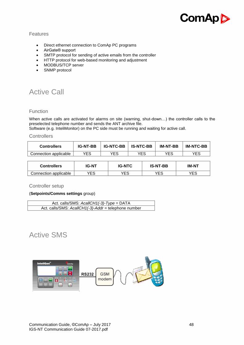
Active SMS
Communication Guide, ©ComAp – July 2017 49 IGS-NT Communication Guide 07-2017.pdf
Function
When SMS active calls are activated for alarms on site (warning, shut-down…) the controller sends SMS message to the predefined GSM number.
Controllers
Controllers IG-NT-BB IG-NTC-BB IS-NTC-BB IM-NT-BB IM-NTC-BB
Connection applicable YES YES YES YES YES
Controllers IG-NT IG-NTC IS-NT-BB IM-NT
Connection applicable YES YES YES YES
Equipment
Equipment needed
Controller side GSM Modem or I-LB+ + GSM Modem
Connection GSM
PC side GSM Mobile Phone
Controller setup
(Setpoints/Comms settings group)
Act. Calls/SMS: AcallCH1(-3)-Type = SMS
Act. calls/SMS: AcallCH1(-3)-Addr = mobil phone number
Act. calls/Acall+SMS lang: AcallCH1(-3)-Addr = 1, 2, 3, ...
Hint: Maximum length of SMS sent in not default language is 70 characters. Number of language corresponds with number of language in GenConfig (card “Languages”).
Example
SMS in format #Gen-set name:AL=(Wrn PrimWater temp, !Emergency stop)
is sent in case that the primary water temperature exceeded the warning limit and Emergency stop input has been deactivated.
Active E-mail (SMS E-mail)
Controllers
Controllers IG-NT-BB IG-NTC-BB IS-NTC-BB IM-NT-BB IM-NTC-BB
Connection applicable YES YES YES YES YES
Available ports external
bridge IB-NT ETHERNET ETHERNET
external bridge IB-NT
ETHERNET
Controllers IG-NT IG-NTC IS-NT-BB IM-NT
Connection applicable YES YES YES YES
Available ports external bridge
IB-NT ETHERNET ETHERNET
external bridge IB-NT

Communication Guide, ©ComAp – July 2017 50 IGS-NT Communication Guide 07-2017.pdf
Equipment
Equipment needed
Controller side Ethernet connection
Connection Internet
PC side Ethernet connection, e-mail message box
Function
When active e-mails are activated for alarms on site (warning, shut-down…) the controller sends e-mail message to the predefined e-mail address. The function and settings for Direct Ethernet port connection and connection via external bridge IG-IB are the same.
Controller setup
(Setpoints/Comms settings group)
Act. calls/SMS: AcallCH1(-3)-Type = IB-E-MAIL
Act. calls/SMS: AcallCH1(-3)-Addr = email address (maximum length of email address is 31 characters)
Act. calls/Acall+SMS lang: AcallCH1(-3)-Addr = 1, 2, 3, ...
Hint: Number of language corresponds with number of language in GenConfig (card “Languages”).
Access Lock
This functionality limits access to the controller, from fully control to monitoring only (it means that commands are blocked, no setpoint changes). The reading all values is still available, change the screens on displays is available. Access Lock is located at LBI card in GenConfig and can be attached to binary input.
Communication Guide, ©ComAp – July 2017 51 IGS-NT Communication Guide 07-2017.pdf
Peripheral modules
Displays
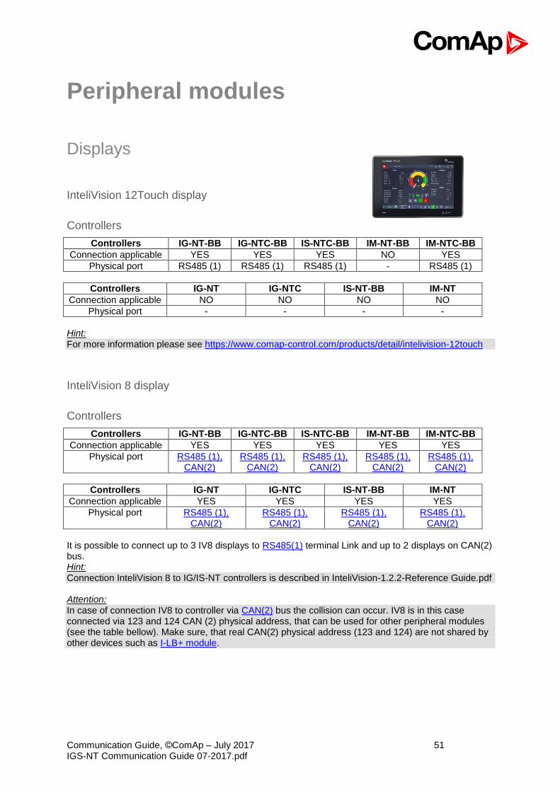
InteliVision 12Touch display
Controllers
Controllers IG-NT-BB IG-NTC-BB IS-NTC-BB IM-NT-BB IM-NTC-BB
Connection applicable YES YES YES NO YES
Physical port RS485 (1) RS485 (1) RS485 (1) - RS485 (1)
Controllers IG-NT IG-NTC IS-NT-BB IM-NT
Connection applicable NO NO NO NO
Physical port - - - -
Hint: For more information please see https://www.comap-control.com/products/detail/intelivision-12touch
InteliVision 8 display
Controllers
Controllers IG-NT-BB IG-NTC-BB IS-NTC-BB IM-NT-BB IM-NTC-BB
Connection applicable YES YES YES YES YES
Physical port RS485 (1), CAN(2)
RS485 (1), CAN(2)
RS485 (1), CAN(2)
RS485 (1), CAN(2)
RS485 (1), CAN(2)
Controllers IG-NT IG-NTC IS-NT-BB IM-NT
Connection applicable YES YES YES YES
Physical port RS485 (1), CAN(2)
RS485 (1), CAN(2)
RS485 (1), CAN(2)
RS485 (1), CAN(2)
It is possible to connect up to 3 IV8 displays to RS485(1) terminal Link and up to 2 displays on CAN(2) bus. Hint: Connection InteliVision 8 to IG/IS-NT controllers is described in InteliVision-1.2.2-Reference Guide.pdf Attention: In case of connection IV8 to controller via CAN(2) bus the collision can occur. IV8 is in this case connected via 123 and 124 CAN (2) physical address, that can be used for other peripheral modules (see the table bellow). Make sure, that real CAN(2) physical address (123 and 124) are not shared by other devices such as I-LB+ module.
Communication Guide, ©ComAp – July 2017 52 IGS-NT Communication Guide 07-2017.pdf
Controller setup
(Setpoints/Comms settings group)
RS485(1) conv. = DISABLED
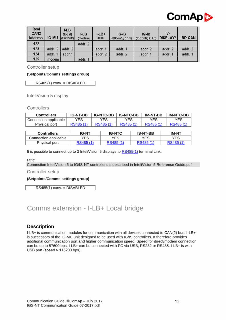
InteliVision 5 display
Controllers
Controllers IG-NT-BB IG-NTC-BB IS-NTC-BB IM-NT-BB IM-NTC-BB
Connection applicable YES YES YES YES YES
Physical port RS485 (1) RS485 (1) RS485 (1) RS485 (1) RS485 (1)
Controllers IG-NT IG-NTC IS-NT-BB IM-NT
Connection applicable YES YES YES YES
Physical port RS485 (1) RS485 (1) RS485 (1) RS485 (1)
It is possible to connect up to 3 InteliVision 5 displays to RS485(1) terminal Link. Hint: Connection InteliVision 5 to IG/IS-NT controllers is described in InteliVision 5 Reference Guide.pdf
Controller setup
(Setpoints/Comms settings group)
RS485(1) conv. = DISABLED
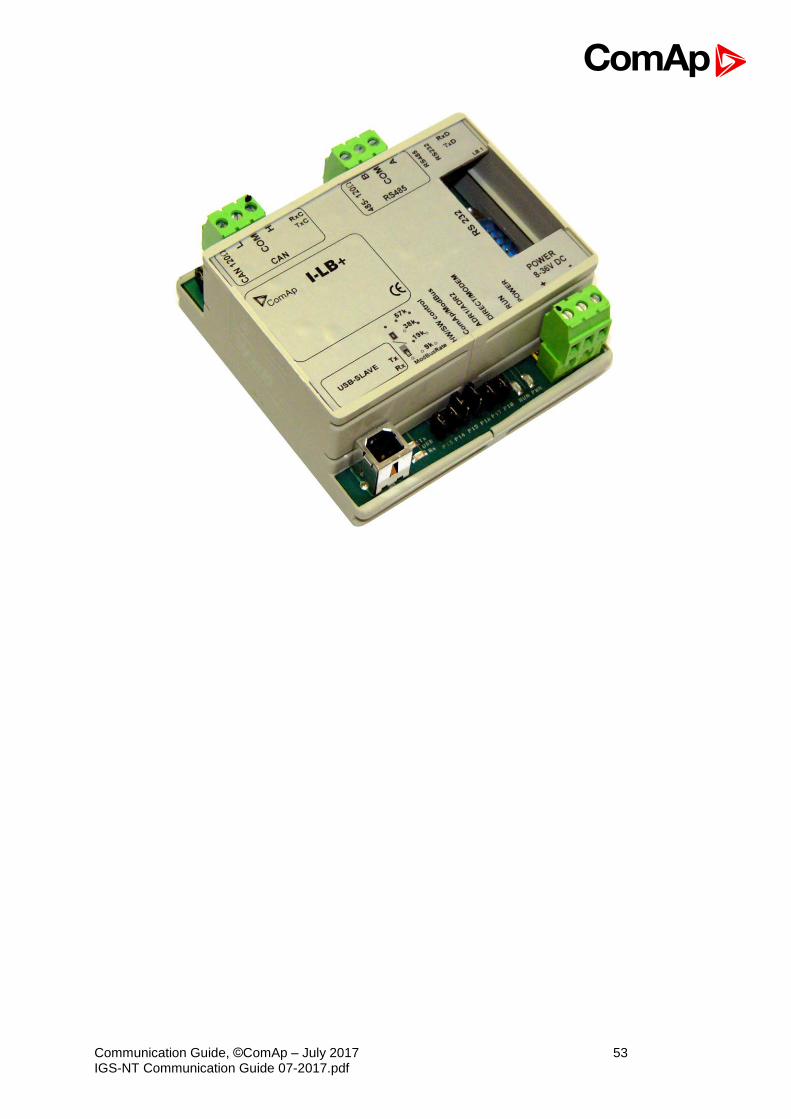
Comms extension - I-LB+ Local bridge
Description
I-LB+ is communication modules for communication with all devices connected to CAN(2) bus. I-LB+ is successors of the IG-MU unit designed to be used with IG/IS controllers. It therefore provides additional communication port and higher communication speed. Speed for direct/modem connection can be up to 57600 bps. I-LB+ can be connected with PC via USB, RS232 or RS485. I-LB+ is with USB port (speed ≈ 115200 bps).
Communication Guide, ©ComAp – July 2017 53 IGS-NT Communication Guide 07-2017.pdf

Communication Guide, ©ComAp – July 2017 54 IGS-NT Communication Guide 07-2017.pdf
Jumper setings:
Jumper Description State
P1 CAN terminating resistor Opened – not connect
P2 RS485 terminating resistor Opened – not connect
P3 RS232 or RS485 1–2 – active RS485
P8 USB enable/disable Opened – disabled
P13 Modbus rate 9600, 19200, 38400, 57600 bps (according to picture: O = Open, C = Close.
P14 Modbus rate
P15 HW or SW modem control Opened – HW control
P16 ComAp or Modbus Opened – ComAp protocol
P17 ADR1 or ADR2 Opened – ADR1
P18 Direct or Modem Opened – Direct
According Addr.1/Addr.2 setings real CAN address is assigned to port.
RS232/485 DIRECT MODEM USB Addr. 1 124 125 123 Addr. 2 123 122 124 It is possible to use those combinations simultaneously:
• 2x direct RS232/RS485 and 2x MODEM (USB communication has to be disabled, P8 is opened)
• 1x USB and 1x RS232/RS485

Communication Guide, ©ComAp – July 2017 55 IGS-NT Communication Guide 07-2017.pdf
Jumper selection tree
ComAp / ModBus – selects between ComAp PC tools (InteliMonitor, WinScope, ...) and third party PC SW for monitoring:
- ComAp o Direct / Modem – selects between direct connection (via RS232 or RS485) and
modem connection type ▪ DIRECT
• RS232 / RS485 – selection of serial communication type
• ADR1 / ADR2 – selection between two available local communication channels; if I-LB+ is used, the USB communication automatically occupies the other channel
▪ MODEM
• HW / SW control – selection between modems with full interface
• ADR1 / ADR2 – selection between two available modem communication channels; IG/IS-NT controllers only, in ID the secondary modem channel not available
• Setting RS232 / RS485 jumper to RS232 position is obligatory
- ModBus (not available at USB port of I-LB+, USB port always works in ComAp mode)
o Direct / Modem – selects between direct connection (via RS232 or RS485) and modem connection type
▪ DIRECT
• RS232 / RS485 – selection of serial communication type
• ADR1 / ADR2 – selection between two available local communication channels; if I-LB+ is used, the USB communication automatically occupies the other channel
▪ MODEM
• ADR1 / ADR2 – selection between two available modem communication channels; IG/IS-NT controllers only, in ID the secondary modem channel not available
• Setting HW / SW control has no influence; a modem with HW control is always expected in this mode
o ModBus Rate (9600 / 19200 / 38400 / 57600 bps) – selects the communication speed when ModBus protocol is selected, no matter if in Direct or Modem mode
For more information read IGS-NT accessory modules manual.
I-CR Module for CAN Bus Extension
If the distance between units is too high to fit into the 200 m limit (or 900 m for 8 controllers), CAN repeater module (I-CR) can be used to extend it. Typical case – in line extension:
total bus length up to 400 m – 32C mode
total segment length up to 200 m total segment length up to 200 m
IG-NT (1)
IG-NT (32)
IG-NT (2)
I-CR A CAN B
IG-NT(x+1
)
IG-NT (x)

Communication Guide, ©ComAp – July 2017 56 IGS-NT Communication Guide 07-2017.pdf
Connection of I-LB, combination of different CAN bus speeds: This connection allows PC communication to all controllers in the system (e.g. via InteliMonitor), including a distant InteliMains unit.
I-CR module functions:
- Intercontroller CAN bus extension (one or more I-CR modules can be used). - Intercontroller CAN bus bus-tie bridging – makes groups of controllers in segments A and B
“invisible” one for another depending on bus-tie breaker state, keeping the PC communication (I-LB, IG-IB) in function for all controllers.
- Peripheral CAN bus extension
I-CR configuration jumpers:
P2 – Forces 250 kbps mode (32C) on CAN A, otherwise speed autodetection is used. P3 – Forces 250 kbps mode (32C) on CAN B, otherwise speed autodetection is used. P4 – Activates Filter mode (bus-tie bridging). P5 – Forces alternate controller address 3 for bus-tie status reading (default controller address is 4). P10 – If “H” network configuration used (two I-CR units), it must be switched to RS-485 mode. For more detailed information about I-CR, see the Application sheet “Extending the CAN bus” or IGS-NT-x.y-Installation guide.pdf. Hint: CAN bus has to be terminated at both ends. In the case of surge hazard (connection out of building in case of storm etc.) see the “CAN and RS485 bus wiring” chapter of the IGS-NT-Installation-Guide-08-2014-r1.pdf.
I-CR-R Module for CAN Bus Redundancy
This module is intended to provide CAN bus redundancy in applications where IG/IS-NT controllers are placed in several switchboards that need to be interconnected by the CAN bus communication line and where there is essential to keep the line working. As a side effect, the module also provides the CAN bus line extension. As the CAN bus provides data exchange needed for Load Sharing and VAr Sharing and also for Power Management features, it’s redundancy can be very important in complex systems with more engines, more mains incomers. Hint: I-CR-R may be used as a redundancy module for a maximum of 20 controllers (counted all controllers on the CAN2 bus). For usage I-CR-R in an installation of more as 20 controllers please contact our technical support for another redundancy solution.
total segment length up to 900 m total segment length up to 200 m
IG-NT (1)
IM (8) IG-NT (x)
I-CR A CAN B
I-LB
Communication Guide, ©ComAp – July 2017 57 IGS-NT Communication Guide 07-2017.pdf
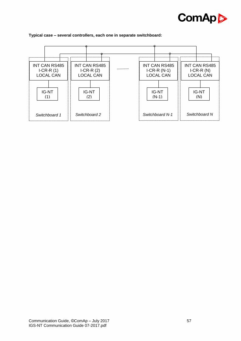
Typical case – several controllers, each one in separate switchboard:
IG-NT (1)
INT CAN RS485 I-CR-R (1)
LOCAL CAN
IG-NT (2)
INT CAN RS485 I-CR-R (2)
LOCAL CAN
IG-NT (N-1)
INT CAN RS485 I-CR-R (N-1) LOCAL CAN
IG-NT (N)
INT CAN RS485 I-CR-R (N)
LOCAL CAN
Switchboard 1 Switchboard 2 Switchboard N-1 Switchboard N
Communication Guide, ©ComAp – July 2017 58 IGS-NT Communication Guide 07-2017.pdf
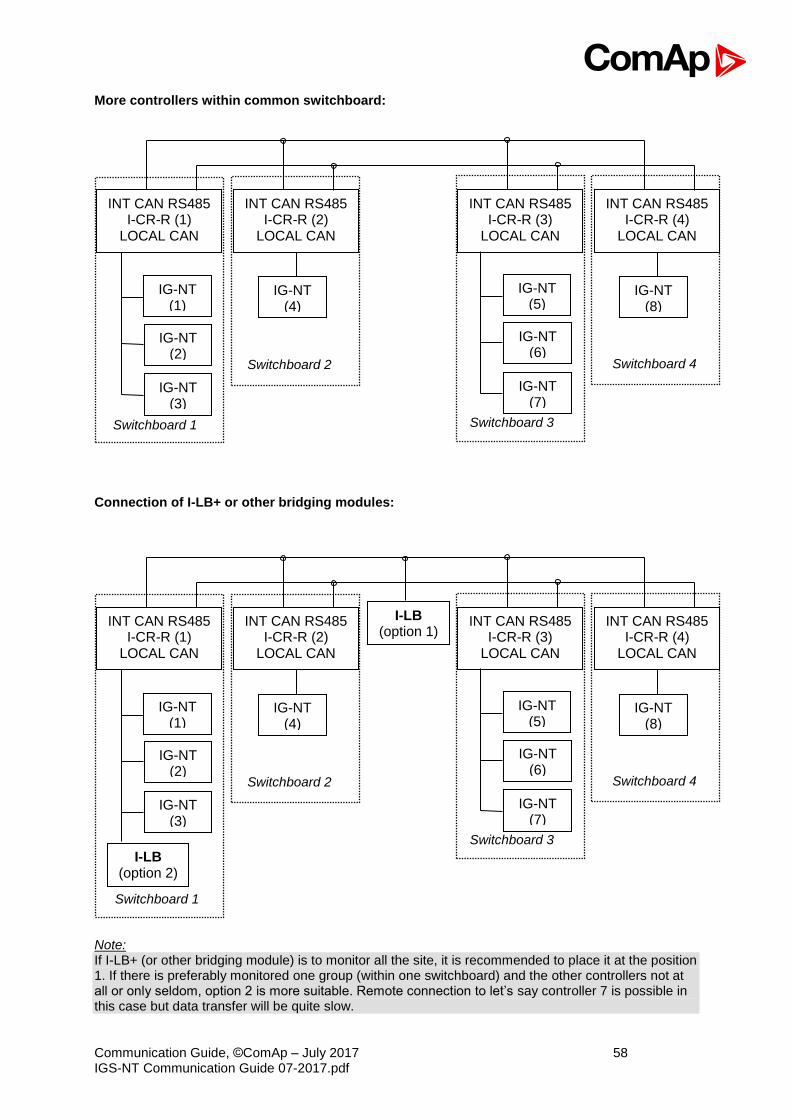
More controllers within common switchboard:
Connection of I-LB+ or other bridging modules:
Note: If I-LB+ (or other bridging module) is to monitor all the site, it is recommended to place it at the position 1. If there is preferably monitored one group (within one switchboard) and the other controllers not at all or only seldom, option 2 is more suitable. Remote connection to let’s say controller 7 is possible in this case but data transfer will be quite slow.
IG-NT (1)
INT CAN RS485 I-CR-R (1)
LOCAL CAN
IG-NT (4)
INT CAN RS485 I-CR-R (2)
LOCAL CAN
INT CAN RS485 I-CR-R (3)
LOCAL CAN
IG-NT (8)
INT CAN RS485 I-CR-R (4)
LOCAL CAN
Switchboard 1
Switchboard 2
Switchboard 3
Switchboard 4
IG-NT (3)
IG-NT (2)
IG-NT (5)
IG-NT (7)
IG-NT (6)
I-LB (option 1)
I-LB (option 2)
IG-NT (1)
INT CAN RS485 I-CR-R (1)
LOCAL CAN
IG-NT (4)
INT CAN RS485 I-CR-R (2)
LOCAL CAN
INT CAN RS485 I-CR-R (3)
LOCAL CAN
IG-NT (8)
INT CAN RS485 I-CR-R (4)
LOCAL CAN
Switchboard 1
Switchboard 2
Switchboard 3
Switchboard 4
IG-NT (3)
IG-NT (2)
IG-NT (5)
IG-NT (7)
IG-NT (6)
Communication Guide, ©ComAp – July 2017 59 IGS-NT Communication Guide 07-2017.pdf
I-CR-R module functions:
- Intercontroller CAN bus redundancy – basic description of terminology used: o Local CAN bus – a bus going from the module to the local controller(s) = within one
switchboard; name on the sticker CAN1 CONTROLLER; in standard installation (with no redundancy) this would be the intercontroller bus (CAN2)
o Primary intercontroller CAN bus – a bus interconnecting all I-CR-R modules and providing 1 to 1 replacement of standard intercontroller CAN bus (CAN2); name on the sticker CAN EMS
o Backup intercontroller RS485 bus – secondary bus interconnecting all I-CR-R modules; transmits only intercontroller communication (Load Sharing, VAr Sharing, Power Management), not the remote communication (I-LB, IG-IB connection to a PC monitoring tool); controller with address 1 must be presented in the system to make backup bus working
- The module preferably uses the Primary CAN bus line for data transfer. However, if the connection from any of the controllers connected to other I-CR-R modules is broken the module automatically re-routes it to the Backup RS485 line and continues in operation. From controllers’ point of view, no data transfer interruption is observed.
- It is possible to indicate the problem with Primary or Backup buses using “fake” SHBOUT6 message which is normally used for signal sharing among the controllers. See jumper description further in the text.
- Intercontroller CAN bus extension – each I-CR-R module provides also CAN bus extension in the same way as I-CR module, i.e. creates segments of the bus where the length of the line is limited within the segment only, not within the whole system.
Note: The redundancy system only makes sense if the cables of Primary and Backup buses are placed physically into different cable routes! Placing them into the same cable route increases the risk of damage of both cables at once.
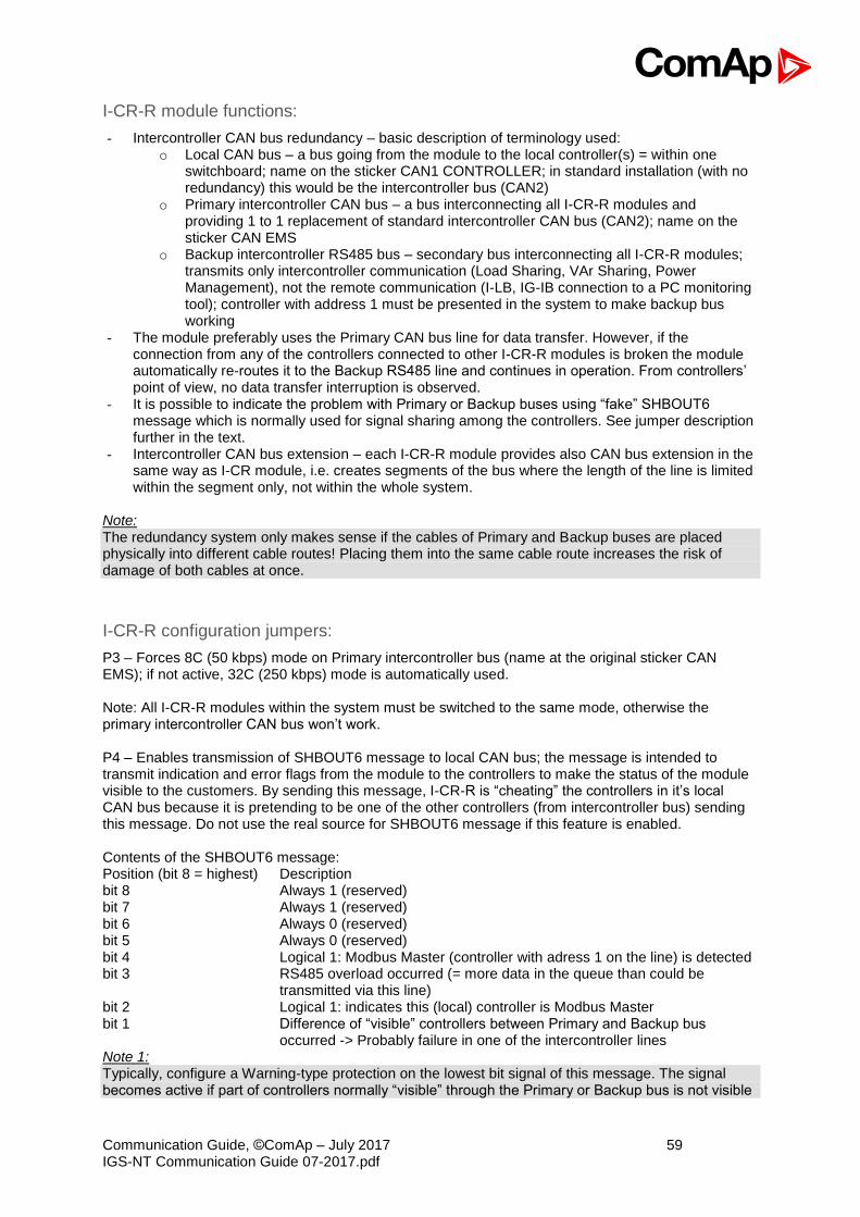
I-CR-R configuration jumpers:
P3 – Forces 8C (50 kbps) mode on Primary intercontroller bus (name at the original sticker CAN EMS); if not active, 32C (250 kbps) mode is automatically used. Note: All I-CR-R modules within the system must be switched to the same mode, otherwise the primary intercontroller CAN bus won’t work. P4 – Enables transmission of SHBOUT6 message to local CAN bus; the message is intended to transmit indication and error flags from the module to the controllers to make the status of the module visible to the customers. By sending this message, I-CR-R is “cheating” the controllers in it’s local CAN bus because it is pretending to be one of the other controllers (from intercontroller bus) sending this message. Do not use the real source for SHBOUT6 message if this feature is enabled. Contents of the SHBOUT6 message: Position (bit 8 = highest) Description bit 8 Always 1 (reserved) bit 7 Always 1 (reserved) bit 6 Always 0 (reserved) bit 5 Always 0 (reserved) bit 4 Logical 1: Modbus Master (controller with adress 1 on the line) is detected bit 3 RS485 overload occurred (= more data in the queue than could be
transmitted via this line) bit 2 Logical 1: indicates this (local) controller is Modbus Master bit 1 Difference of “visible” controllers between Primary and Backup bus
occurred -> Probably failure in one of the intercontroller lines Note 1: Typically, configure a Warning-type protection on the lowest bit signal of this message. The signal becomes active if part of controllers normally “visible” through the Primary or Backup bus is not visible
Communication Guide, ©ComAp – July 2017 60 IGS-NT Communication Guide 07-2017.pdf
anymore; this means the cable was cut or shorted or otherwise damaged and doesn’t connect anymore some part or all the controllers. Note 2: Because bit 1 activates with the difference between Primary and Backup buses it is able to indicate failures of both Primary and Backup buses, so even if Primary bus works fine, it is able to show the problem with Backup bus to allow the technician to repair it before it actually becomes a problem. Otherwise the problem with the Backup bus would stay hidden until Primary bus would have failed and then the intercontroller communication would stop working completely.
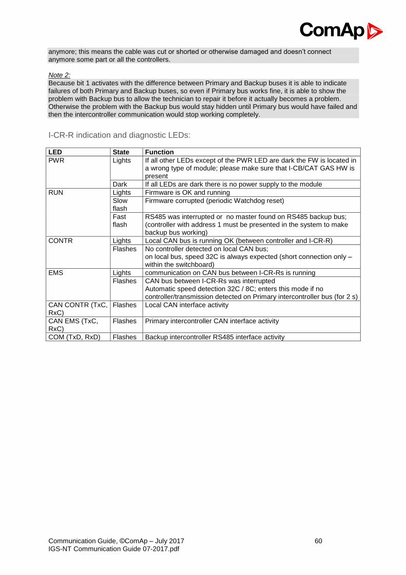
I-CR-R indication and diagnostic LEDs:
LED State Function
PWR Lights If all other LEDs except of the PWR LED are dark the FW is located in a wrong type of module; please make sure that I-CB/CAT GAS HW is present
Dark If all LEDs are dark there is no power supply to the module
RUN Lights Firmware is OK and running
Slow flash
Firmware corrupted (periodic Watchdog reset)
Fast flash
RS485 was interrupted or no master found on RS485 backup bus; (controller with address 1 must be presented in the system to make backup bus working)
CONTR Lights Local CAN bus is running OK (between controller and I-CR-R)
Flashes No controller detected on local CAN bus; on local bus, speed 32C is always expected (short connection only – within the switchboard)
EMS Lights communication on CAN bus between I-CR-Rs is running
Flashes CAN bus between I-CR-Rs was interrupted Automatic speed detection 32C / 8C; enters this mode if no controller/transmission detected on Primary intercontroller bus (for 2 s)
CAN CONTR (TxC, RxC)
Flashes Local CAN interface activity
CAN EMS (TxC, RxC)
Flashes Primary intercontroller CAN interface activity
COM (TxD, RxD) Flashes Backup intercontroller RS485 interface activity

Communication Guide, ©ComAp – July 2017 61 IGS-NT Communication Guide 07-2017.pdf
Appendix
Communication cables
Recommended communication cables for ComAp controllers Interface Cable Connector max. Length Max. Comm.
Rate RS232 Serial cross-wired cable
standard Null-modem cable DB 9 DB 9
10 m 57.6kBd
RS485 Shield twisted pair 1) NONE 1000 m 57.6kBd Ethernet STP or UTP cable RJ45 100 m 10/100 Mbps USB Standard USB A-B cable USB A-USB B 5 m 115200 Bd CAN Shield twisted pair 2) NONE 200 m / 900 m 250 kBd 1) RS 485 cable B) For longer distances: 3106A Paired - EIA Industrial RS-485 PLTC/CM (1x2+1 conductors) Recommended data cables: BELDEN (http://www.belden.com) A) For shorter distances (up to 50 m): 3105A Paired - EIA Industrial RS-485 PLTC/CM (1x2 conductors) 2) CAN bus cable Galvanically separated Maximal CAN bus length 200m Speed 250kBd Nominal impedance 120Ω Cable type twisted pair (shielded) Following dynamic cable parameters are important especially for maximal 200 meters CAN bus length and 32 iS-COM units connected: Nominal Velocity of Propagation min. 75% (max. 4,4 ns/m) Recommended data cables: BELDEN (http://www.belden.com) A) For shorter distances (up to 50 m): 3105A Paired - EIA Industrial RS-485 PLTC/CM (1x2 conductors)
B) For longer distances: 3106A Paired - EIA Industrial RS-485 PLTC/CM (1x2+1 conductors)
In case of surge hazard: 3106A Paired - EIA Industrial RS-485 PLTC/CM (1x2+1 conductors)
RS232 cable
It is recommended to use standard Null-modem cable for local connection between controller and PC, although the three wires (TxD, RxD, GND) RS 232 connection is enough for direct controller to PC communication:

Communication Guide, ©ComAp – July 2017 62 IGS-NT Communication Guide 07-2017.pdf
Cables for direct and modem connections
PC to RS232 on controller / I-LB DB9 Female to DB9 Female
2 3 3 2 5 5
Modem to RS232 on controller / I-LB Comms settings: MODEM (HW) or I-LB jumper HW control DB9 Male to DB9 Female
1 1 2 2 3 3 4 4 5 5 6 6 7 7 8 8 9 9
Comms settings: MODEM (SW) or I-LB jumper SW control DB9 Male to DB9 Female
2 2 3 3 5 5
USB cable
Use standard USB A-B cable (distance up to 5 meters).
CAUTION! Use shielded USB cable only! (ComAp order code: USB-LINK CABLE 1.8m) ! IMPORTANT ! To use USB connection it is necessary to install drivers on your PC. The drivers can be downloaded from the website http://www.ftdichip.com/Drivers/VCP.htm. Download the driver for your operating system and follow the enclosed instructions.
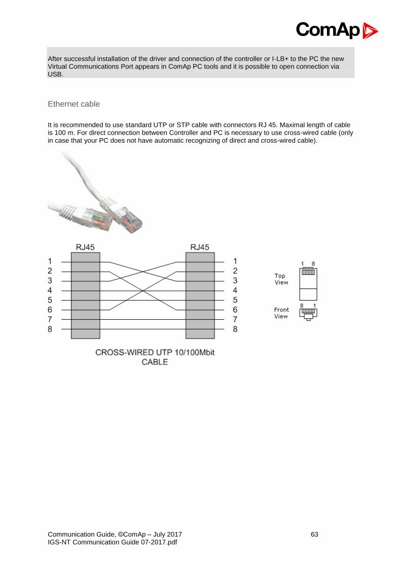
Communication Guide, ©ComAp – July 2017 63 IGS-NT Communication Guide 07-2017.pdf
After successful installation of the driver and connection of the controller or I-LB+ to the PC the new Virtual Communications Port appears in ComAp PC tools and it is possible to open connection via USB.
Ethernet cable
It is recommended to use standard UTP or STP cable with connectors RJ 45. Maximal length of cable is 100 m. For direct connection between Controller and PC is necessary to use cross-wired cable (only in case that your PC does not have automatic recognizing of direct and cross-wired cable).
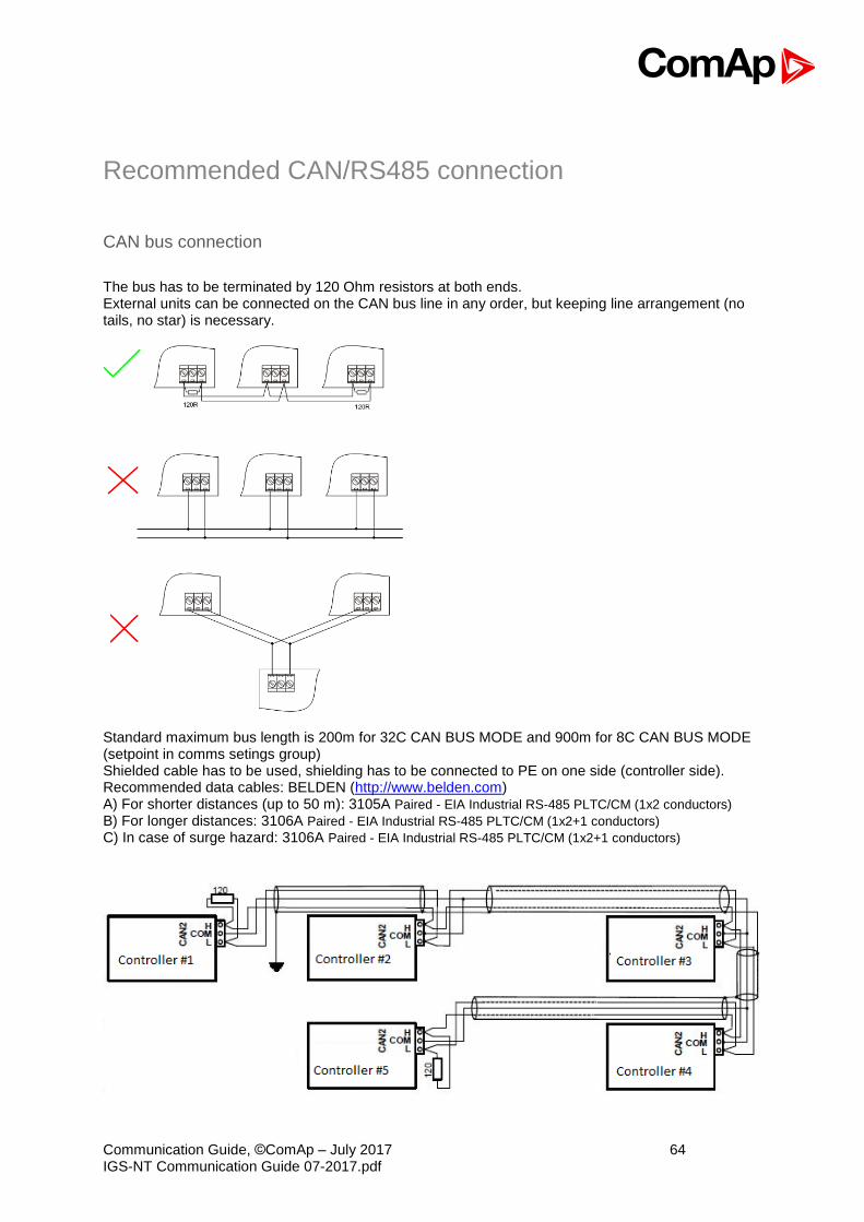
Communication Guide, ©ComAp – July 2017 64 IGS-NT Communication Guide 07-2017.pdf
Recommended CAN/RS485 connection
CAN bus connection
The bus has to be terminated by 120 Ohm resistors at both ends. External units can be connected on the CAN bus line in any order, but keeping line arrangement (no tails, no star) is necessary.
Standard maximum bus length is 200m for 32C CAN BUS MODE and 900m for 8C CAN BUS MODE (setpoint in comms setings group) Shielded cable has to be used, shielding has to be connected to PE on one side (controller side). Recommended data cables: BELDEN (http://www.belden.com) A) For shorter distances (up to 50 m): 3105A Paired - EIA Industrial RS-485 PLTC/CM (1x2 conductors)
B) For longer distances: 3106A Paired - EIA Industrial RS-485 PLTC/CM (1x2+1 conductors)
C) In case of surge hazard: 3106A Paired - EIA Industrial RS-485 PLTC/CM (1x2+1 conductors)
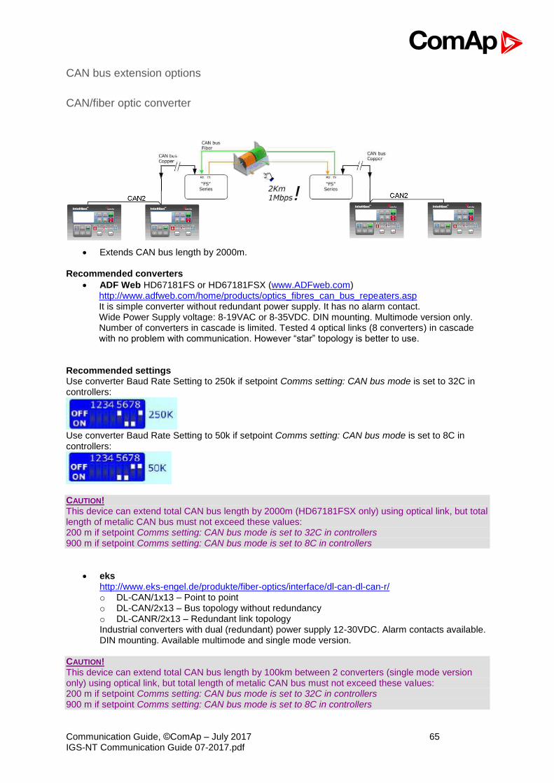
Communication Guide, ©ComAp – July 2017 65 IGS-NT Communication Guide 07-2017.pdf
CAN bus extension options
CAN/fiber optic converter
• Extends CAN bus length by 2000m.
Recommended converters
• ADF Web HD67181FS or HD67181FSX (www.ADFweb.com) http://www.adfweb.com/home/products/optics_fibres_can_bus_repeaters.asp It is simple converter without redundant power supply. It has no alarm contact. Wide Power Supply voltage: 8-19VAC or 8-35VDC. DIN mounting. Multimode version only. Number of converters in cascade is limited. Tested 4 optical links (8 converters) in cascade with no problem with communication. However “star” topology is better to use.
Recommended settings Use converter Baud Rate Setting to 250k if setpoint Comms setting: CAN bus mode is set to 32C in controllers:
Use converter Baud Rate Setting to 50k if setpoint Comms setting: CAN bus mode is set to 8C in controllers:
CAUTION! This device can extend total CAN bus length by 2000m (HD67181FSX only) using optical link, but total length of metalic CAN bus must not exceed these values: 200 m if setpoint Comms setting: CAN bus mode is set to 32C in controllers 900 m if setpoint Comms setting: CAN bus mode is set to 8C in controllers
• eks http://www.eks-engel.de/produkte/fiber-optics/interface/dl-can-dl-can-r/ o DL-CAN/1x13 – Point to point o DL-CAN/2x13 – Bus topology without redundancy o DL-CANR/2x13 – Redundant link topology Industrial converters with dual (redundant) power supply 12-30VDC. Alarm contacts available. DIN mounting. Available multimode and single mode version.
CAUTION! This device can extend total CAN bus length by 100km between 2 converters (single mode version only) using optical link, but total length of metalic CAN bus must not exceed these values: 200 m if setpoint Comms setting: CAN bus mode is set to 32C in controllers 900 m if setpoint Comms setting: CAN bus mode is set to 8C in controllers
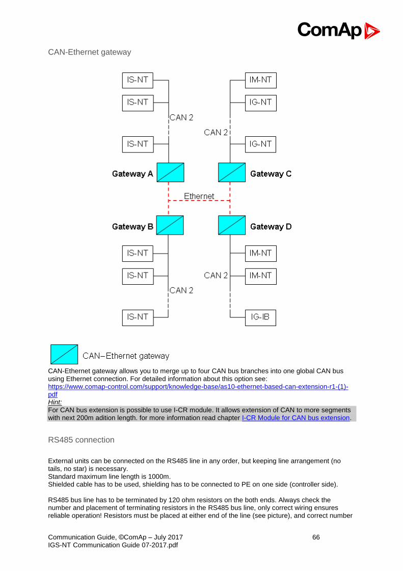
Communication Guide, ©ComAp – July 2017 66 IGS-NT Communication Guide 07-2017.pdf
CAN-Ethernet gateway
CAN-Ethernet gateway allows you to merge up to four CAN bus branches into one global CAN bus using Ethernet connection. For detailed information about this option see: https://www.comap-control.com/support/knowledge-base/as10-ethernet-based-can-extension-r1-(1)-pdf Hint: For CAN bus extension is possible to use I-CR module. It allows extension of CAN to more segments with next 200m adition length. for more information read chapter I-CR Module for CAN bus extension.
RS485 connection
External units can be connected on the RS485 line in any order, but keeping line arrangement (no tails, no star) is necessary. Standard maximum line length is 1000m. Shielded cable has to be used, shielding has to be connected to PE on one side (controller side). RS485 bus line has to be terminated by 120 ohm resistors on the both ends. Always check the number and placement of terminating resistors in the RS485 bus line, only correct wiring ensures reliable operation! Resistors must be placed at either end of the line (see picture), and correct number
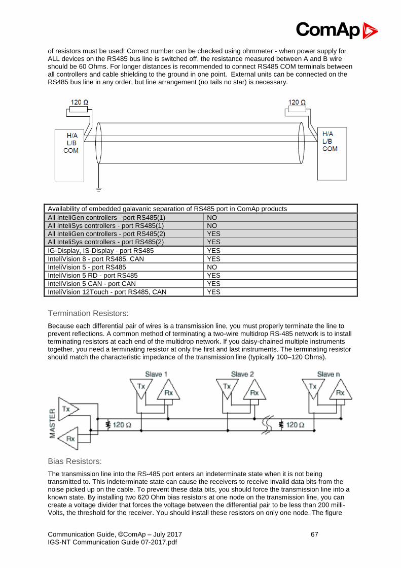
Communication Guide, ©ComAp – July 2017 67 IGS-NT Communication Guide 07-2017.pdf
of resistors must be used! Correct number can be checked using ohmmeter - when power supply for ALL devices on the RS485 bus line is switched off, the resistance measured between A and B wire should be 60 Ohms. For longer distances is recommended to connect RS485 COM terminals between all controllers and cable shielding to the ground in one point. External units can be connected on the RS485 bus line in any order, but line arrangement (no tails no star) is necessary.
Availability of embedded galavanic separation of RS485 port in ComAp products
All InteliGen controllers - port RS485(1) NO
All InteliSys controllers - port RS485(1) NO
All InteliGen controllers - port RS485(2) YES
All InteliSys controllers - port RS485(2) YES
IG-Display, IS-Display - port RS485 YES
InteliVision 8 - port RS485, CAN YES
InteliVision 5 - port RS485 NO
InteliVision 5 RD - port RS485 YES
InteliVision 5 CAN - port CAN YES
InteliVision 12Touch - port RS485, CAN YES
Termination Resistors:
Because each differential pair of wires is a transmission line, you must properly terminate the line to prevent reflections. A common method of terminating a two-wire multidrop RS-485 network is to install terminating resistors at each end of the multidrop network. If you daisy-chained multiple instruments together, you need a terminating resistor at only the first and last instruments. The terminating resistor should match the characteristic impedance of the transmission line (typically 100–120 Ohms).
Bias Resistors:
The transmission line into the RS-485 port enters an indeterminate state when it is not being transmitted to. This indeterminate state can cause the receivers to receive invalid data bits from the noise picked up on the cable. To prevent these data bits, you should force the transmission line into a known state. By installing two 620 Ohm bias resistors at one node on the transmission line, you can create a voltage divider that forces the voltage between the differential pair to be less than 200 milli-Volts, the threshold for the receiver. You should install these resistors on only one node. The figure

Communication Guide, ©ComAp – July 2017 68 IGS-NT Communication Guide 07-2017.pdf
below shows a transmission line using bias resistors. Bias resistors are placed directly on the PCB of controller. Use jumpers PULL UP / PULL DOWN to connect the bias resistors.
Converters
Converter RS232 RS485
General properties of RS232 to RS485 converters:
• Has to be set to passive DSR signal (when DSR connected) after switch on.
• No external data flow control signals are allowed – automatic data flow control required.
Recommended converters
• External: ADAM 4520, ADVANTECH, (http://www.advantech.com/) - DIN rail, automatic RS485 bus supervision, no external data flow control signals, galvanic isolated, baud rate 19200 bps - When communication is working the LED on ADAM 4520 is going from full illumination to short darkness then again full illuminated - When communication of I-LB is working, PWR and RUN LEDs full red illuminated; TxD and RxD flashing when transmitting
ADAM 4520
PC RS232
(not crossed)
A
B
I-LB IG/IS-NT ID
RS485 Jumper for RS485
connected
SW1: 1 closed (10bit)
SW2: 6 closed
DATA+
DATA-

Communication Guide, ©ComAp – July 2017 69 IGS-NT Communication Guide 07-2017.pdf
Hint: In the case of surge hazard (connection out of building in case of storm etc.) see the “Recommended CAN/RS485 connection” chapter of the IGS-NT-2.2-Installation guide.pdf.
RS232 Bluetooth adapter
Recommended adapter
BL-830 (http://www.brainboxes.com/category/bluetooth.aspx) – doesn’t work with Windows Vista
Converter USB RS232
• Useful for PC/laptops without serial port
Recommended converters
• UCAB232 Full, ASIX (http://www.asix.cz/) UCAB232 is designated for all standard RS232 devices (mouses, modems, data terminals, barcode readers, serial printers) and industrial applications. UCAB232 supports Baud rates from 300 Bd to 250 kBaud (guaranteed) / 500 kBaud (typ.).
• VPI - USS-101/111, VPI (http://www.vpi.us/usb-serial.html) Supports serial devices with speeds up to 230kb/sec (e.g. PDAs, modems, scanners, etc.).
• C-232-MM, (http://www.usbgear.com/item_288.html) The USB Serial Adapter provides instant connectivity with modems, ISDN TAs, PDS, handheld & pocket PCs, digital cameras, POS, serial printers, etc. It supports data rates up to 230 Kbps.
USB RS232 PC
IL,ID, IG/IS-NT
USB RS232
PC
ETHERNET ADAPTER
IG-IB IG/IS-NT
ID
ETHERNET ADAPTER
CAN ETHERNET ETHERNET 230 V
RS232
PC BL-830
RS232 BL-830
10 - 30 m Controller

Communication Guide, ©ComAp – July 2017 70 IGS-NT Communication Guide 07-2017.pdf
Converter USB RS485
• Extends distance between PC and controller up to 1200 meters
Recommended converter
• SB485S, SB485C, SB585L PaPouch elektronika (http://www.papouch.com/)
Converter CAN CAN
• Allows to change the baudrate. Can be usefull to connect specific types of ECU.
• Allows to map CAN identifier to another. Usefull in case of collision at the CAN bus.
• Allows to filter range of CAN identifiers. May be appropriate at sites with heavy traffic on the CAN bus.
Recommended converter
• I-7532: http://www.icpdas.com/root/product/solutions/industrial_communication/fieldbus/can_bus/repeater/i-7532.html From FW 1.4 and higher allows to map short CAN identifiers to long and vice versa.
CAN 250 kbit/s
CAN 500 kbit/s
USB RS485
RS485 RS232
PC IL,ID,
IG/IS-NT
RS232 USB RS485
ECU J1939 500 kbit/s
CAN-CAN converter
IG/IS-NT
Peripheral modules

Communication Guide, ©ComAp – July 2017 71 IGS-NT Communication Guide 07-2017.pdf
Recommended optical USB extension cables
• Opticis M2-100-xx http://opticis.com
• USB Rover 200 http://www.icron.com
Radio Link
• Useful when the control room is distant from the site
• Can be more economical than to hard wire it
PC RL-2400E IB-NT IG/IS-NT
ID
CAN ETHERNET ETHERNET RL-2400E 1 km

Communication Guide, ©ComAp – July 2017 72 IGS-NT Communication Guide 07-2017.pdf
Recommended equipment
• RadioLinx RL-2400E wireless Ethernet switch, ProSoft Technology Inc. (www.prosoft-technology.com)
• ADAM-4571, ADVANTECH (www.advantech.com)
• MOXA DE311, MOXA (www.moxa.com)
• MOXA Nport 5230, MOXA
Converter Modbus RTU Profibus
GE Digital Energy - P485 Modbus to Profibus Converter
• For connection of 1-32 NT line controllers to a Profibus network
• RS485 or RS232 physical layer for connection to the controller(s)
• Full Profibus-DP slave functionality according IEC61158
• 244 bytes input data size (122 Modbus registers)
• 244 bytes output data size (122 Modbus registers)
• 416 bytes total
• See deatils on the web page of the manufacturer: http://www.gedigitalenergy.com/multilin/catalog/p485.htm
IGS-NT
RS485 (RS232)
Profibus
Profibus Master
Pro
fibus D
P
Modbus RTU
IGS-NT
IGS-NT

Communication Guide, ©ComAp – July 2017 73 IGS-NT Communication Guide 07-2017.pdf
Converter settings
• Use EnerVista software to setup the converter. It can be downloaded from the web page http://pm.geindustrial.com/download/download.asp?id=p485&file=1.
• To configure the converter in the Profibus network, download the description file http://www.geindustrial.com/products/software/d485/P48509E5.zip and import it to the Profibus configuration tool.
Follow instructions in the P485 manual while configuring the converter. The setup wizard incorporated in the Enervista software will make the setup process much easier, but finally some manual corrections are needed. Below are some notes specific to the connection with ComAp controllers.
1. The physical layer for Modbus communication is select table. The selected type (RS232/RS485) and speed must be same in the P485 and controller, see Controller settings.
2. Use RS485 in case more controllers are connected to the P485. 3. A Device mentioned in the wizard represents a controller type (IG-NT, IM-NT, IS-NT).
Once a device is defined, more nodes of the same type (device) can be created easily. 4. A modbus network node represents a controller. The slave address must correspond to
the Controller address setpoint of the related controller. 5. See Modbus Connection chapter in this document for details about Modbus, register
numbers, sizes etc. 6. Use triggered update mode for writing objects (registers) to the controller. Never
use cyclic update mode!
Setup example (using wizard): 1. Select wizard.
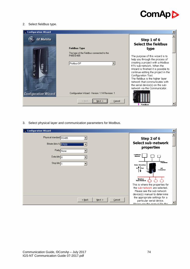
Communication Guide, ©ComAp – July 2017 74 IGS-NT Communication Guide 07-2017.pdf
2. Select fieldbus type.
3. Select physical layer and communication parameters for Modbus.

Communication Guide, ©ComAp – July 2017 75 IGS-NT Communication Guide 07-2017.pdf
4. Define IGS-NT Device, it’s Parameters and related Modbus registers.
5. Define nodes connected to the Modbus network.

Communication Guide, ©ComAp – July 2017 76 IGS-NT Communication Guide 07-2017.pdf
6. For each node select parameters that have to be mapped to the Profibus network.
7. Save the configuration overview (the picture below is only a general example, not a real one).
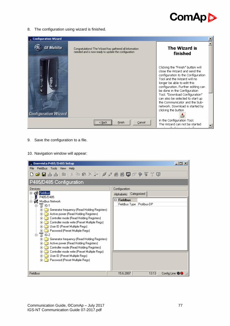
Communication Guide, ©ComAp – July 2017 77 IGS-NT Communication Guide 07-2017.pdf
8. The configuration using wizard is finished.
9. Save the configuration to a file. 10. Navigation window will appear:
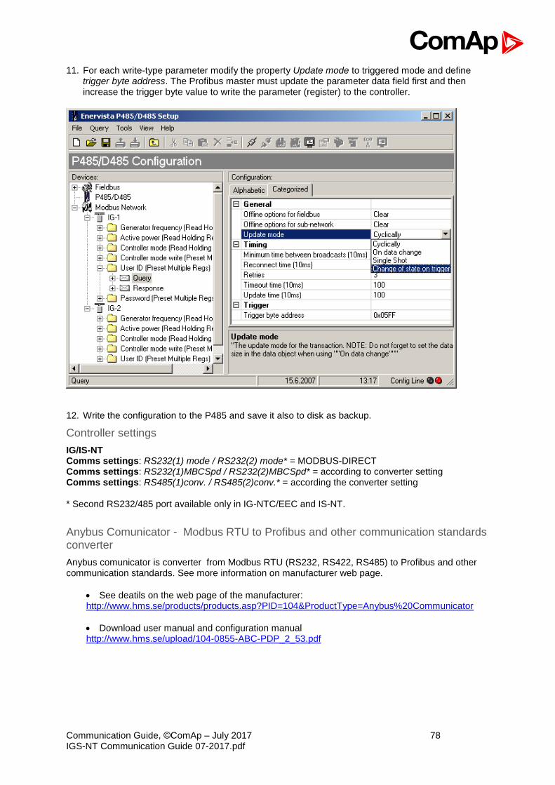
Communication Guide, ©ComAp – July 2017 78 IGS-NT Communication Guide 07-2017.pdf
11. For each write-type parameter modify the property Update mode to triggered mode and define trigger byte address. The Profibus master must update the parameter data field first and then increase the trigger byte value to write the parameter (register) to the controller.
12. Write the configuration to the P485 and save it also to disk as backup.
Controller settings
IG/IS-NT Comms settings: RS232(1) mode / RS232(2) mode* = MODBUS-DIRECT Comms settings: RS232(1)MBCSpd / RS232(2)MBCSpd* = according to converter setting Comms settings: RS485(1)conv. / RS485(2)conv.* = according the converter setting * Second RS232/485 port available only in IG-NTC/EEC and IS-NT.
Anybus Comunicator - Modbus RTU to Profibus and other communication standards converter
Anybus comunicator is converter from Modbus RTU (RS232, RS422, RS485) to Profibus and other communication standards. See more information on manufacturer web page.
• See deatils on the web page of the manufacturer: http://www.hms.se/products/products.asp?PID=104&ProductType=Anybus%20Communicator
• Download user manual and configuration manual http://www.hms.se/upload/104-0855-ABC-PDP_2_53.pdf
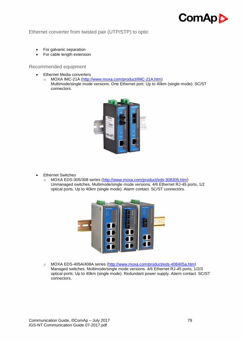
Communication Guide, ©ComAp – July 2017 79 IGS-NT Communication Guide 07-2017.pdf
Ethernet converter from twisted pair (UTP/STP) to optic
• For galvanic separation
• For cable length extension
Recommended equipment
• Ethernet Media converters o MOXA IMC-21A (http://www.moxa.com/product/IMC-21A.htm)
Multimode/single mode versions. One Ethernet port. Up to 40km (single mode). SC/ST connectors.
• Ethernet Switches o MOXA EDS-305/308 series (http://www.moxa.com/product/eds-308305.htm)
Unmanaged switches. Multimode/single mode versions. 4/6 Ethernet RJ-45 ports, 1/2 optical ports. Up to 40km (single mode). Alarm contact. SC/ST connectors.
o MOXA EDS-405A/408A series (http://www.moxa.com/product/eds-408405a.htm)
Managed switches. Multimode/single mode versions. 4/6 Ethernet RJ-45 ports, 1/2/3 optical ports. Up to 40km (single mode). Redundant power supply. Alarm contact. SC/ST connectors.
Communication Guide, ©ComAp – July 2017 80 IGS-NT Communication Guide 07-2017.pdf
SMS message commands
Controller address
Controller address is unique controller identification number located in setpoint group Basic setting : Contr addr [1 to 32]. Syntax: #XX
XX … controller address [1 to 32]
Example: #5
Message is addressed to controller with address 5.
Access code
InteliGen / InteliSys Access code is 15 characters length string. Access code is separated from controller address by column. Syntax: #5:X
X … controller access code up to 15 characters length
Example: #5:accesscode
Message is addressed to controller with address 5 and its access code is set
to value ‘accesscode’.
Read value or setpoint
Command for reading of selected value or setpoint. Return value is in appropriate numerical or string format. Syntax: r XXXX (or rXXXX)
r … command
XXXX… value or setpoint code
Example: #5:accesscode r 8252
Reading of setpoint 8252 (8252 = Gear teeth) Hint: Access code can’t contain space character. Access code can be changed in InteliMonitor only.
Adjust setpoint
Command for adjusting of selected setpoint. Answer message contains only confirmation of successful adjusting or appropriate error. Syntax: w XXXX YYYY (or wXXXX YYYY)
w … command
XXXX… setpoint code
YYYY… value of setpoint in appropriate format
Example: #5:accesscode w 8252 144
Adjusting of setpoint 8252 to value 144 (8252 = Gear teeth).
Return code: ok … adjusting setpoint was correct
w_err … adjusting setpoint was not successful
er_pass … adjusting setpoint required that valid password was entered
er_old … command for adjusting was read out from SMS during
GSM modem initialization – in this case command will not be served.
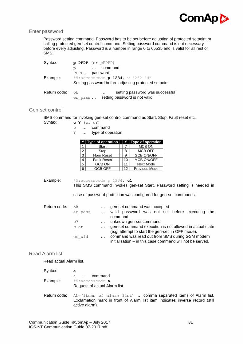
Communication Guide, ©ComAp – July 2017 81 IGS-NT Communication Guide 07-2017.pdf
Enter password
Password setting command. Password has to be set before adjusting of protected setpoint or calling protected gen-set control command. Setting password command is not necessary before every adjusting. Password is a number in range 0 to 65535 and is valid for all rest of SMS. Syntax: p PPPP (or pPPPP)
p … command
PPPP… password
Example: #5:accesscode p 1234, w 8252 144
Setting password before adjusting protected setpoint.
Return code: ok … setting password was successful
er_pass … setting password is not valid
Gen-set control
SMS command for invoking gen-set control command as Start, Stop, Fault reset etc. Syntax: c Y (or cY)
c … command
Y … type of operation
Y Type of operation Y Type of operation
1 Start 7 MCB ON
2 Stop 8 MCB OFF
3 Horn Reset 9 GCB ON/OFF
4 Fault Reset 10 MCB ON/OFF
5 GCB ON 11 Next Mode
6 GCB OFF 12 Previous Mode
Example: #5:accesscode p 1234, c1
This SMS command invokes gen-set Start. Password setting is needed in
case of password protection was configured for gen-set commands.
Return code: ok … gen-set command was accepted
er_pass … valid password was not set before executing the
command
c? … unknown gen-set command
c_er … gen-set command execution is not allowed in actual state
(e.g. attempt to start the gen-set in OFF mode).
er_old … command was read out from SMS during GSM modem
initialization – in this case command will not be served.
Read Alarm list
Read actual Alarm list. Syntax: a
a … command
Example: #5:accesscode a
Request of actual Alarm list.
Return code: AL=(items of alarm list) … comma separated items of Alarm list.
Exclamation mark in front of Alarm list item indicates inverse record (still active alarm).

Communication Guide, ©ComAp – July 2017 82 IGS-NT Communication Guide 07-2017.pdf
Note: 1. Answer message contains at most eight items of Alarm list. 2. Alarm list is not separated to more messages.
Time delay
Insert time delay before serving next part of SMS command. Syntax: d T
d … command
T … time delay in sec (in range 1 to 600)
Example: #5:accesscode d 10
Request 10 sec delay before serving next SMS command.
Return code: d_ok … time delay was successful performed
d_over … requested time delay is out of range (1 to 600 sec)
Note: Any other SMS messages are not served during time delay!
Remote switches (IG/IS-NT only)
Set or reset RemoteControl1-8 output.
Syntax: s 1/0
s … command
1/0 … set/reset
Example: #5:accesscode p0, s1 1
Enters password p0 and sets RemoteControl1 output.
Return code: p_OK,s_OK
ExtValues (IG/IS-NT only)
Enters value to ExtValue.
Syntax: e xxx
e … command
xxx … value Example: #5:accesscode p0, e1 50
Enters password p0 and sets ExtValue1 = 50. Return code: p_OK,e_OK
Help (IG/IS-NT only)
Request for list of supported SMS command. Syntax: ?
Example: #5:accesscode ?
Return code: ?=(p <user:>passwd,r comm_obj,w com_obj val,c cmd_num,d sec,a,sx y,ex y,?)…... ..... list of supported SMS commands
Note: Return code is not separated to more message.
Answer message
Answer message start with # character followed by Gen-set name. Colon separates this header form return codes of SMS commands. Answer message is generated during serving of received message and is sent in case that 160 characters or end of received message are achieved. Answer message is sent to the originator phone number. Tree dots at the end of message indicate separation and next following message.

Communication Guide, ©ComAp – July 2017 83 IGS-NT Communication Guide 07-2017.pdf
Example: #5:accesscode r8252,w8252 100,r8252
answer message #Gen-setname: 144,ok,100
Examples of SMS commands
Here is following several examples of SMS messages addresses to controller IG/IS-NT with address 5, named ‘Gen-set name’. Access code in this controller is set to ‘accesscode’ and password is ‘1234’. In examples are used setpoints and values 8276 – Nomin.power, 10123 – RPM, 8315 – Controller Mode, 8235 – binary inputs, 8296 – Gen > f.
Example 1 – reading value
SMS:
#5:accesscode r8276 read value 8276
Answer:
#Gen-set name:100
Example 2 – adjusting setpoint SMS: #5:accesscode p 1234, r8276,w8276
110,r8276 read value 8276, write 110, read value 8276
Answer: #Gen-set name:ok,100,ok,110 Password was accepted, read value of 8276 is 100, writing to 8276 was ok, new value of 8276 is 110
If wrong password sent: #Gen-set name:p_er,100, w_pass, 100
Password was not accepted, read value of 8276 is 100 writing to 8276 was not successful read value of 8276 is still 100
Example 3 – Gen-set control and delay time SMS: #5:accesscode
r8276,c1,d30,r10123 read value 8276, invoke gen-set command START, delay 30 sec, read value 10123
Answer: #Gen-set name:110,ok,d_ok,1499 read value of 8276 is 110, Gen-set command START was accepted, confirm delay command, read value of 10123 is 1499
Example 4 – adjusting special setpoint SMS: #5:accesscode r8315,w8315
0,r8315 read value 8315, write 0 (index of stringlist type), read value 8315
Answer: #Gen-set name:MAN,ok,OFF read value of 8315 as string, writing was ok, read new value of 8315 as string
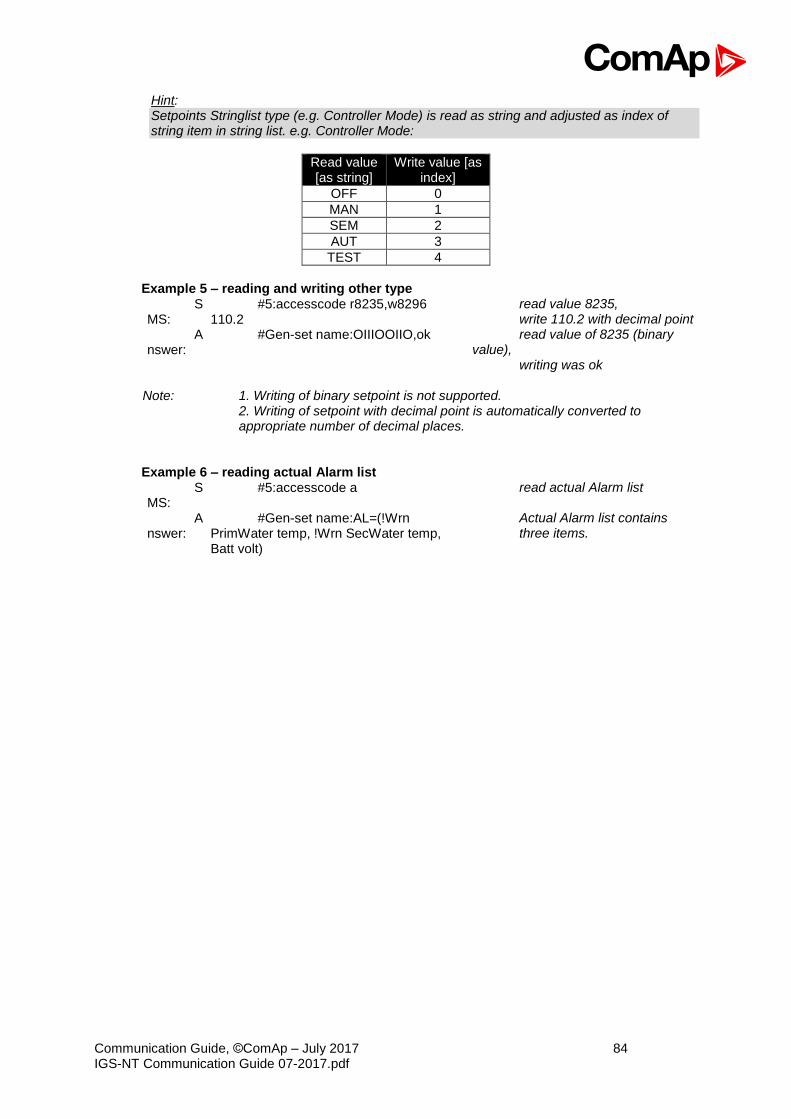
Communication Guide, ©ComAp – July 2017 84 IGS-NT Communication Guide 07-2017.pdf
Hint: Setpoints Stringlist type (e.g. Controller Mode) is read as string and adjusted as index of string item in string list. e.g. Controller Mode:
Read value [as string]
Write value [as index]
OFF 0
MAN 1
SEM 2
AUT 3
TEST 4
Example 5 – reading and writing other type
SMS:
#5:accesscode r8235,w8296 110.2
read value 8235, write 110.2 with decimal point
Answer:
#Gen-set name:OIIIOOIIO,ok read value of 8235 (binary value),
writing was ok Note: 1. Writing of binary setpoint is not supported. 2. Writing of setpoint with decimal point is automatically converted to
appropriate number of decimal places. Example 6 – reading actual Alarm list
SMS:
#5:accesscode a read actual Alarm list
Answer:
#Gen-set name:AL=(!Wrn PrimWater temp, !Wrn SecWater temp, Batt volt)
Actual Alarm list contains three items.
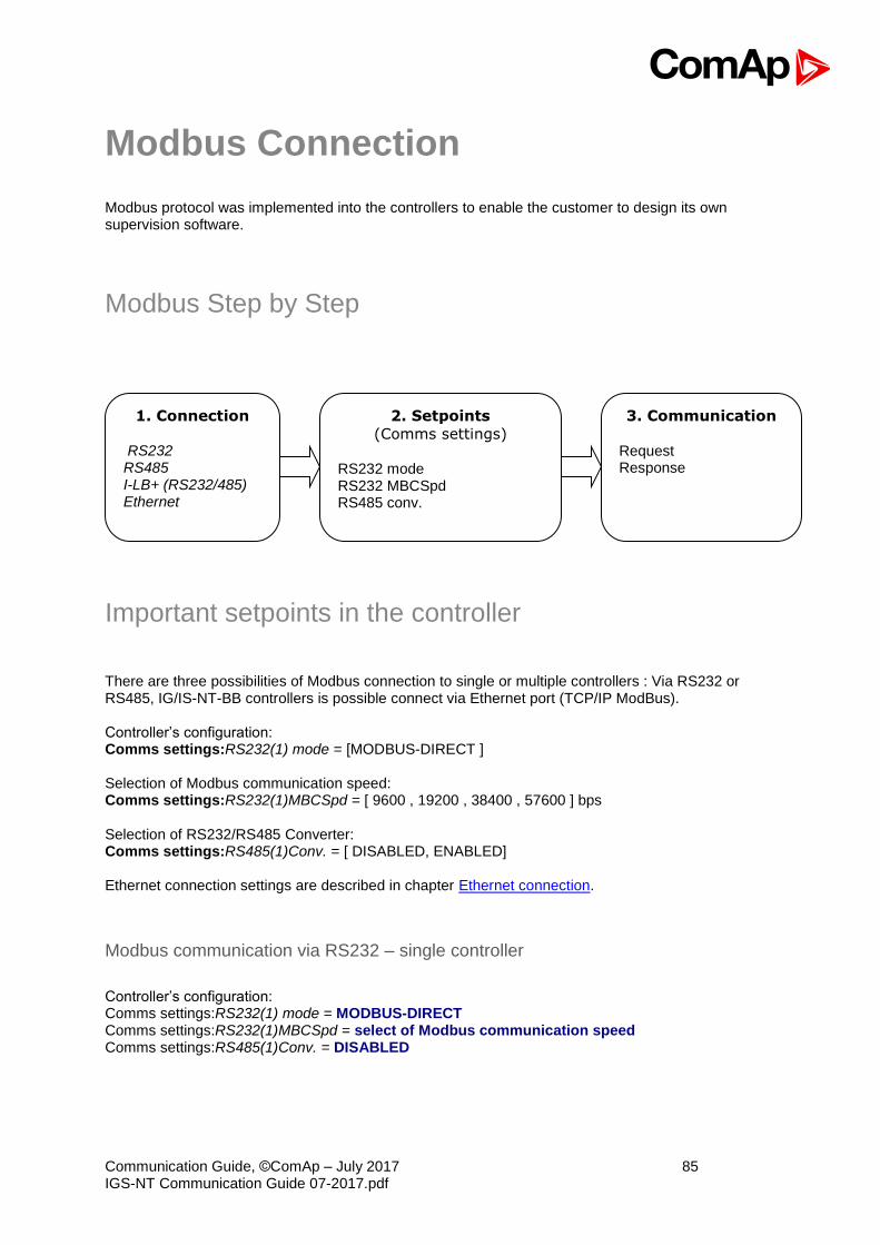
Communication Guide, ©ComAp – July 2017 85 IGS-NT Communication Guide 07-2017.pdf
Modbus Connection
Modbus protocol was implemented into the controllers to enable the customer to design its own supervision software.
Modbus Step by Step
Important setpoints in the controller
There are three possibilities of Modbus connection to single or multiple controllers : Via RS232 or RS485, IG/IS-NT-BB controllers is possible connect via Ethernet port (TCP/IP ModBus). Controller’s configuration: Comms settings:RS232(1) mode = [MODBUS-DIRECT ] Selection of Modbus communication speed: Comms settings:RS232(1)MBCSpd = [ 9600 , 19200 , 38400 , 57600 ] bps Selection of RS232/RS485 Converter: Comms settings:RS485(1)Conv. = [ DISABLED, ENABLED] Ethernet connection settings are described in chapter Ethernet connection.
Modbus communication via RS232 – single controller
Controller’s configuration: Comms settings:RS232(1) mode = MODBUS-DIRECT Comms settings:RS232(1)MBCSpd = select of Modbus communication speed Comms settings:RS485(1)Conv. = DISABLED
1. Connection
RS232 RS485 I-LB+ (RS232/485) Ethernet
2. Setpoints
(Comms settings)
RS232 mode RS232 MBCSpd RS485 conv.
3. Communication
Request Response
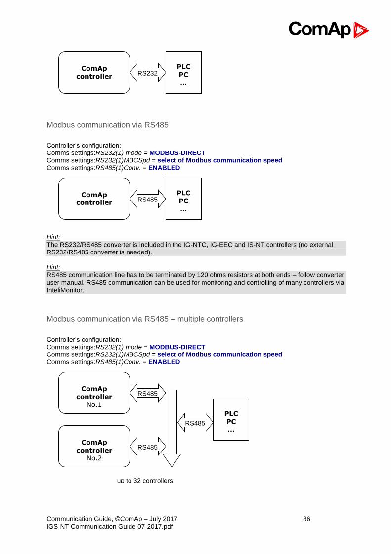
Communication Guide, ©ComAp – July 2017 86 IGS-NT Communication Guide 07-2017.pdf
Modbus communication via RS485
Controller’s configuration: Comms settings:RS232(1) mode = MODBUS-DIRECT Comms settings:RS232(1)MBCSpd = select of Modbus communication speed Comms settings:RS485(1)Conv. = ENABLED
Hint: The RS232/RS485 converter is included in the IG-NTC, IG-EEC and IS-NT controllers (no external RS232/RS485 converter is needed). Hint: RS485 communication line has to be terminated by 120 ohms resistors at both ends – follow converter user manual. RS485 communication can be used for monitoring and controlling of many controllers via InteliMonitor.
Modbus communication via RS485 – multiple controllers
Controller’s configuration: Comms settings:RS232(1) mode = MODBUS-DIRECT Comms settings:RS232(1)MBCSpd = select of Modbus communication speed Comms settings:RS485(1)Conv. = ENABLED
ComAp controller
PLC
PC
…
RS485
ComAp
controller
No.1
PLC
PC …
ComAp
controller No.2
RS485
RS485
RS485
ComAp
controller
PLC
PC …
RS232
up to 32 controllers

Communication Guide, ©ComAp – July 2017 87 IGS-NT Communication Guide 07-2017.pdf
Modbus communication via I-LB+
I-LB+ configuration: Jumpers P13, P14 = select of Modbus communication speed Jumper P16 = Modbus Jumper P17 = Address 1 or Address 2 Jumper P18 = Direct
Hint: To use I-LB Modbus communication connect Modbus jumper in I-LB unit (P16). Additionally, you can choose the communication speed using the speed selection jumpers (P13, P14). Their combination allows the speed selection of 9600 / 19200 / 38400 / 57600 bps.
Modbus communication via IB-NT
Modbus communication needst to be enabled in settings via IB-NT config. Modbus is available as Modbus TCP or Modbus RTU over RS485. Hint: For more information regarding IB-NT please see documentation https://www.comap-control.com/products/detail/internetbridge-nt .
ComAp
controller No.1
PLC
PC …
ComAp
controller No.2
RS232 I-LB+
USB
CAN2
CAN2
CAN2S485
up to 32 controllers
RS232 or USB
Communication Guide, ©ComAp – July 2017 88 IGS-NT Communication Guide 07-2017.pdf
Modbus Communication
Hint: It is possible to define your own Modbus register numbers for any value or setpoint in the BaseBox controllers with standard FW v3.0 (IG-NT-BB, IS-NT-BB and IM-NT-BB firmware) and higher. For more information about this function please refer to the chapter User Modbus. Hint: In the firs time, you have to correctly configure the controller connection.
Data reading
The function Read Multiple Registers has to be used for data reading. The terminal sends a query and from the controller receives either the normal response containing the requested data or the exceptional response indicating a read error.
• It is possible to use function 3 for reading (Read Multiple Registers).
• It is not possible to read from the middle. The register number must correspond with the beginning of the data object. The only exception are the objects of „multipacket values“ (registers 46367 – 46491) and „data part of the history record“ (registers 46543 – 46667).
• All read registers must be implemented. If an unimplemented register appears among the read registers, the controller returns an error message.
• Even unnamed values can be included among read registers (See Cfg image - column Name = (N/A)). The read value must be treated as meaningless.
• The length of a block is 127 registers.
Data writing
All data can be written by the function Write Multiple Registers. Data up to 2 bytes can be written by the function Write Single Register, too. The terminal sends a query containing a written data and the controller either confirms it (normal response) or refuses it (exceptional response).
• For writing it is possible to use function 6 (Write Single Register) or function 16 (Write Multiple Registers).
• Using function 16 it is possible to write maximum 16 registers at once.
• Data cannot be written from the middle. Register number must correspond with the beginning of the data object. Written data must be complete to perform writing of all requested data objects.
• Writing to EEPROM is executed using a queue. The queue is common for writing from all terminals. The request for next writing is accepted in case that there is empty space in the queue. Otherwise the controller returns an error message and the terminal must repeat the request.
• All written registers must be implemented. If an unimplemented register appears among the read registers, the controller returns an error message.
• It is possible to include also unnamed registers in the written sequence (See Cfg image - column Name = (N/A)). The controller confirms this writing but writing of
unnamed registers is not performed.
Request :

Communication Guide, ©ComAp – July 2017 89 IGS-NT Communication Guide 07-2017.pdf
- controller address (1 - 32), you can set or check your controller’s address in the controller setpoints. Setpoints -> Comms settings -> Contr.address
- Modbus function code, you can use the 3, 6, 16 Modbus function code,
Function 3 (Read Multiple Registers) Function 6 (Write Single Register) Command 10 Function 16 (Write Multiple Registers)
- Register address (40001 - 47168), it means Modbus address of controller communication
object (setpoint, value, et al.). You can crate list of Modbus registers, if you can’t find the register address in this list, see the table of dedicated communication objects.
- Number of registers (1 - 127). It means, how many registers you want read. - CRC (no range)
After sent your request, you receive the response. The response has also five parts:
- Controller address (1 - 32), the same as the address in the request - Modbus function code (3,6,16, …), mostly the same as in the request - Length of data (1 - 127), here is specified the length of the received data - Data (0 - FF), data are in the HEX form, length is defined above - CRC (no range)
Hint: The setpoints in IG-NT are placed in EEPROM which has maximum 500 000 of rewrites. Please consider how fast the setpoints are overwritten. (1 sec writing period, 6 days ~ 500 000 rewrites). IS-NTC-BB using memory with maximum of 500 000 000 rewrites.

Communication Guide, ©ComAp – July 2017 90 IGS-NT Communication Guide 07-2017.pdf
Modbus Protocol Description
Modbus TCP
• Direct connection:
ETH
Port 502
• Bridge connection: - IB-NT
• Transfer mode TCP/IP
• Function codes - 3 (Read Multiple Registers) - 6 (Write Single Register) - 10 (Command) - 16 (Write Multiple Registers)
• The response to an incoming message depends on the network performace and on the controller configuration. Typical response time is 25 ms.
• Connection timeout is set to 15 seconds. If no message comes within the timeout then controller close the connection.
Hint: Data structure is the same as Modbus RTU. Modbus TCP adds 6 bytes header before data. CRC calculation is not used in Modbus TCP.
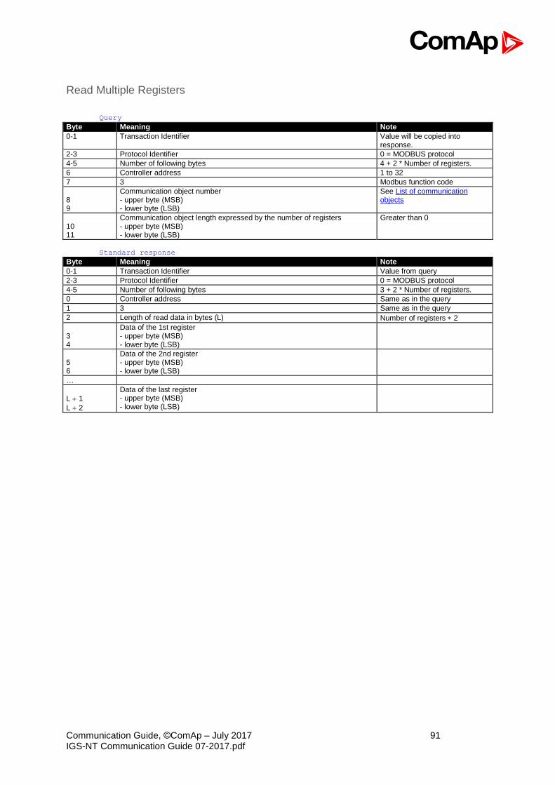
Communication Guide, ©ComAp – July 2017 91 IGS-NT Communication Guide 07-2017.pdf
Read Multiple Registers
Query Byte Meaning Note
0-1 Transaction Identifier Value will be copied into response.
2-3 Protocol Identifier 0 = MODBUS protocol
4-5 Number of following bytes 4 + 2 * Number of registers.
6 Controller address 1 to 32
7 3 Modbus function code
8 9
Communication object number - upper byte (MSB) - lower byte (LSB)
See List of communication objects
10 11
Communication object length expressed by the number of registers - upper byte (MSB) - lower byte (LSB)
Greater than 0
Standard response Byte Meaning Note
0-1 Transaction Identifier Value from query
2-3 Protocol Identifier 0 = MODBUS protocol
4-5 Number of following bytes 3 + 2 * Number of registers.
0 Controller address Same as in the query
1 3 Same as in the query
2 Length of read data in bytes (L) Number of registers 2
3 4
Data of the 1st register - upper byte (MSB) - lower byte (LSB)
5 6
Data of the 2nd register - upper byte (MSB) - lower byte (LSB)
…
L 1
L 2
Data of the last register - upper byte (MSB) - lower byte (LSB)

Communication Guide, ©ComAp – July 2017 92 IGS-NT Communication Guide 07-2017.pdf
Modbus RTU
• Direct connection:
RS232, RS485, (I-LB+), (IB-NT)
8 data bits
1 stop bit
no parity
• Modem connection
8 data bits
1 stop bit
no parity
• Communication speed:
9600 / 19200 / 38400 / 57600 bps
• Transfer mode RTU
• Function codes - 3 (Read Multiple Registers) - 6 (Write Single Register) - 10 (Command) - 16 (Write Multiple Registers)
• The response to an incoming message depends on the communication speed. The delay is not shorter than the time needed to send/receive 3 and ½ characters.
The complete description of Modbus communication protocol can be found in http://modbus.org/docs/PI_MBUS_300.pdf and http://www.rtaautomation.com/modbustcp/files/Open_ModbusTCP_Standard.pdf.
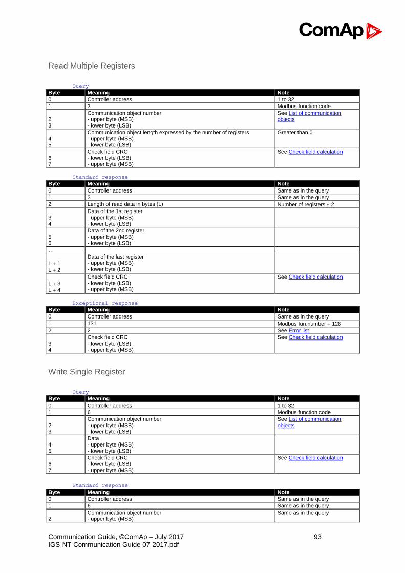
Communication Guide, ©ComAp – July 2017 93 IGS-NT Communication Guide 07-2017.pdf
Read Multiple Registers
Query Byte Meaning Note
0 Controller address 1 to 32
1 3 Modbus function code
2 3
Communication object number - upper byte (MSB) - lower byte (LSB)
See List of communication objects
4 5
Communication object length expressed by the number of registers - upper byte (MSB) - lower byte (LSB)
Greater than 0
6 7
Check field CRC - lower byte (LSB) - upper byte (MSB)
See Check field calculation
Standard response Byte Meaning Note
0 Controller address Same as in the query
1 3 Same as in the query
2 Length of read data in bytes (L) Number of registers 2
3 4
Data of the 1st register - upper byte (MSB) - lower byte (LSB)
5 6
Data of the 2nd register - upper byte (MSB) - lower byte (LSB)
…
L 1
L 2
Data of the last register - upper byte (MSB) - lower byte (LSB)
L 3
L 4
Check field CRC - lower byte (LSB) - upper byte (MSB)
See Check field calculation
Exceptional response Byte Meaning Note
0 Controller address Same as in the query
1 131 Modbus fun.number 128
2 2 See Error list
3 4
Check field CRC - lower byte (LSB) - upper byte (MSB)
See Check field calculation
Write Single Register
Query Byte Meaning Note
0 Controller address 1 to 32
1 6 Modbus function code
2 3
Communication object number - upper byte (MSB) - lower byte (LSB)
See List of communication objects
4 5
Data - upper byte (MSB) - lower byte (LSB)
6 7
Check field CRC - lower byte (LSB) - upper byte (MSB)
See Check field calculation
Standard response Byte Meaning Note
0 Controller address Same as in the query
1 6 Same as in the query
2
Communication object number - upper byte (MSB)
Same as in the query
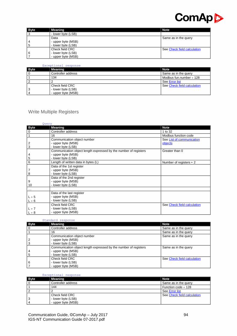
Communication Guide, ©ComAp – July 2017 94 IGS-NT Communication Guide 07-2017.pdf
Byte Meaning Note
3 - lower byte (LSB)
4 5
Data - upper byte (MSB) - lower byte (LSB)
Same as in the query
6 7
Check field CRC - lower byte (LSB) - upper byte (MSB)
See Check field calculation
Exceptional response Byte Meaning Note
0 Controller address Same as in the query
1 134 Modbus fun.number 128
2 2 See Error list
3 4
Check field CRC - lower byte (LSB) - upper byte (MSB)
See Check field calculation
Write Multiple Registers
Query Byte Meaning Note
0 Controller address 1 to 32
1 16 Modbus function code
2 3
Communication object number - upper byte (MSB) - lower byte (LSB)
See List of communication objects
4 5
Communication object length expressed by the number of registers - upper byte (MSB) - lower byte (LSB)
Greater than 0
6 Length of written data in bytes (L) Number of registers 2
7 8
Data of the 1st register - upper byte (MSB) - lower byte (LSB)
9 10
Data of the 2nd register - upper byte (MSB) - lower byte (LSB)
…
L 5
L 6
Data of the last register - upper byte (MSB) - lower byte (LSB)
L 7
L 8
Check field CRC - lower byte (LSB) - upper byte (MSB)
See Check field calculation
Standard response Byte Meaning Note
0 Controller address Same as in the query
1 16 Same as in the query
2 3
Communication object number - upper byte (MSB) - lower byte (LSB)
Same as in the query
4 5
Communication object length expressed by the number of registers - upper byte (MSB) - lower byte (LSB)
Same as in the query
6 7
Check field CRC - lower byte (LSB) - upper byte (MSB)
See Check field calculation
Exceptional response Byte Meaning Note
0 Controller address Same as in the query
1 144 Function code 128
2 2 See Error list
3 4
Check field CRC - lower byte (LSB) - upper byte (MSB)
See Check field calculation
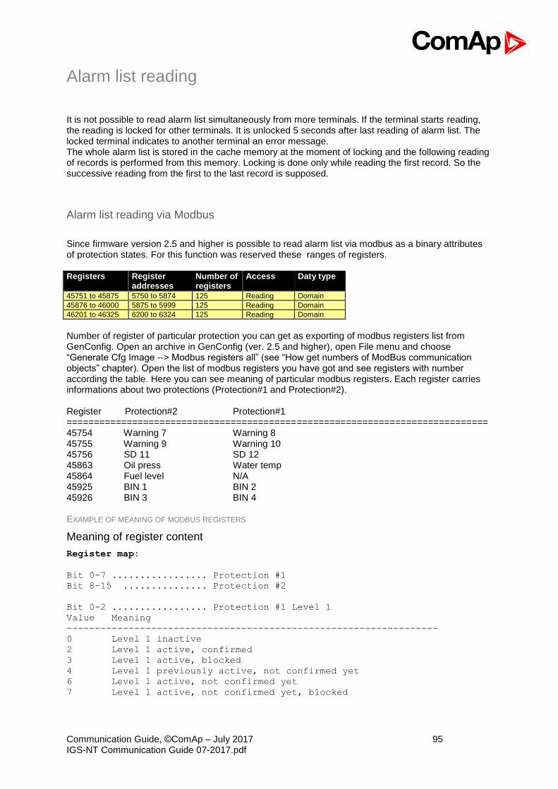
Communication Guide, ©ComAp – July 2017 95 IGS-NT Communication Guide 07-2017.pdf
Alarm list reading
It is not possible to read alarm list simultaneously from more terminals. If the terminal starts reading, the reading is locked for other terminals. It is unlocked 5 seconds after last reading of alarm list. The locked terminal indicates to another terminal an error message. The whole alarm list is stored in the cache memory at the moment of locking and the following reading of records is performed from this memory. Locking is done only while reading the first record. So the successive reading from the first to the last record is supposed.
Alarm list reading via Modbus
Since firmware version 2.5 and higher is possible to read alarm list via modbus as a binary attributes of protection states. For this function was reserved these ranges of registers. Registers Register
addresses Number of registers
Access
Daty type
45751 to 45875 5750 to 5874 125 Reading Domain
45876 to 46000 5875 to 5999 125 Reading Domain
46201 to 46325 6200 to 6324 125 Reading Domain
Number of register of particular protection you can get as exporting of modbus registers list from GenConfig. Open an archive in GenConfig (ver. 2.5 and higher), open File menu and choose “Generate Cfg Image --> Modbus registers all” (see “How get numbers of ModBus communication objects” chapter). Open the list of modbus registers you have got and see registers with number according the table. Here you can see meaning of particular modbus registers. Each register carries informations about two protections (Protection#1 and Protection#2). Register Protection#2 Protection#1 ============================================================================= 45754 Warning 7 Warning 8 45755 Warning 9 Warning 10 45756 SD 11 SD 12 45863 Oil press Water temp 45864 Fuel level N/A 45925 BIN 1 BIN 2 45926 BIN 3 BIN 4 EXAMPLE OF MEANING OF MODBUS REGISTERS
Meaning of register content
Register map:
Bit 0-7 ................. Protection #1
Bit 8-15 ............... Protection #2
Bit 0-2 ................. Protection #1 Level 1
Value Meaning
------------------------------------------------------------------
0 Level 1 inactive
2 Level 1 active, confirmed
3 Level 1 active, blocked
4 Level 1 previously active, not confirmed yet
6 Level 1 active, not confirmed yet
7 Level 1 active, not confirmed yet, blocked
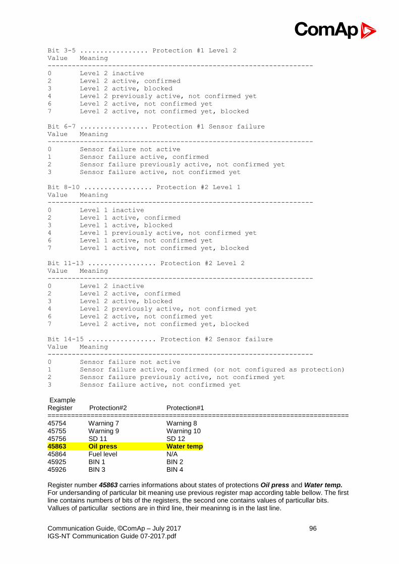
Communication Guide, ©ComAp – July 2017 96 IGS-NT Communication Guide 07-2017.pdf
Bit 3-5 ................. Protection #1 Level 2
Value Meaning
------------------------------------------------------------------
0 Level 2 inactive
2 Level 2 active, confirmed
3 Level 2 active, blocked
4 Level 2 previously active, not confirmed yet
6 Level 2 active, not confirmed yet
7 Level 2 active, not confirmed yet, blocked
Bit 6-7 ................. Protection #1 Sensor failure
Value Meaning
------------------------------------------------------------------
0 Sensor failure not active
1 Sensor failure active, confirmed
2 Sensor failure previously active, not confirmed yet
3 Sensor failure active, not confirmed yet
Bit 8-10 ................. Protection #2 Level 1
Value Meaning
------------------------------------------------------------------
0 Level 1 inactive
2 Level 1 active, confirmed
3 Level 1 active, blocked
4 Level 1 previously active, not confirmed yet
6 Level 1 active, not confirmed yet
7 Level 1 active, not confirmed yet, blocked
Bit 11-13 ................. Protection #2 Level 2
Value Meaning
------------------------------------------------------------------
0 Level 2 inactive
2 Level 2 active, confirmed
3 Level 2 active, blocked
4 Level 2 previously active, not confirmed yet
6 Level 2 active, not confirmed yet
7 Level 2 active, not confirmed yet, blocked
Bit 14-15 ................. Protection #2 Sensor failure
Value Meaning
------------------------------------------------------------------
0 Sensor failure not active
1 Sensor failure active, confirmed (or not configured as protection)
2 Sensor failure previously active, not confirmed yet
3 Sensor failure active, not confirmed yet
Example Register Protection#2 Protection#1 ============================================================================= 45754 Warning 7 Warning 8 45755 Warning 9 Warning 10 45756 SD 11 SD 12 45863 Oil press Water temp 45864 Fuel level N/A 45925 BIN 1 BIN 2 45926 BIN 3 BIN 4 Register number 45863 carries informations about states of protections Oil press and Water temp. For undersanding of particular bit meaning use previous register map according table bellow. The first line contains numbers of bits of the registers, the second one contains values of particullar bits. Vallues of particullar sections are in third line, their meaninng is in the last line.
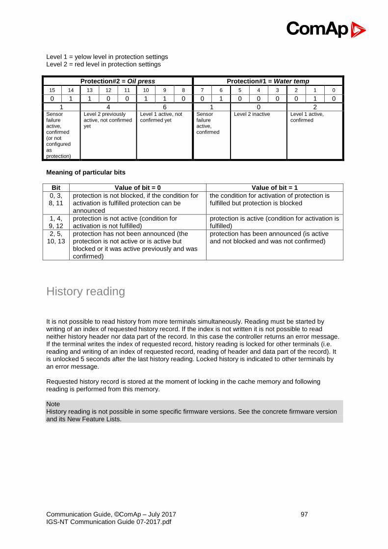
Communication Guide, ©ComAp – July 2017 97 IGS-NT Communication Guide 07-2017.pdf
Level 1 = yelow level in protection settings Level 2 = red level in protection settings
Protection#2 = Oil press Protection#1 = Water temp
15 14 13 12 11 10 9 8 7 6 5 4 3 2 1 0
0 1 1 0 0 1 1 0 0 1 0 0 0 0 1 0
1 4 6 1 0 2 Sensor failure active, confirmed (or not configured as protection)
Level 2 previously active, not confirmed yet
Level 1 active, not confirmed yet
Sensor failure active, confirmed
Level 2 inactive Level 1 active, confirmed
Meaning of particular bits
Bit Value of bit = 0 Value of bit = 1
0, 3, 8, 11
protection is not blocked, if the condition for activation is fulfilled protection can be announced
the condition for activation of protection is fulfilled but protection is blocked
1, 4, 9, 12
protection is not active (condition for activation is not fulfilled)
protection is active (condition for activation is fulfilled)
2, 5, 10, 13
protection has not been announced (the protection is not active or is active but blocked or it was active previously and was confirmed)
protection has been announced (is active and not blocked and was not confirmed)
History reading
It is not possible to read history from more terminals simultaneously. Reading must be started by writing of an index of requested history record. If the index is not written it is not possible to read neither history header nor data part of the record. In this case the controller returns an error message. If the terminal writes the index of requested record, history reading is locked for other terminals (i.e. reading and writing of an index of requested record, reading of header and data part of the record). It is unlocked 5 seconds after the last history reading. Locked history is indicated to other terminals by an error message. Requested history record is stored at the moment of locking in the cache memory and following reading is performed from this memory. Note History reading is not possible in some specific firmware versions. See the concrete firmware version and its New Feature Lists.

Communication Guide, ©ComAp – July 2017 98 IGS-NT Communication Guide 07-2017.pdf
Check field calculation
The check field allows the receiver to check the validity of the message. The check field value is the Cyclical Redundancy Check (CRC) based on the polynomial x16+x15+x2+1. CRC is counted from all message bytes preceding the check field.
How get numbers of ModBus communication objects
Communication objects can be spitted into two groups: 1. Communication objects
dependent on the application type (SSB, SPM, SPtM, MEXT, MINT, …).
2. Communication objects independent on the application type.
Use GenConfig menu command File –> Generate Cfg Image –> Generate Cfg Image (Comm. Objects …) and Generate Cfg Image (Modbus Registers all/used).
A part of Cfg Image (Modbus Register …) file

Communication Guide, ©ComAp – July 2017 99 IGS-NT Communication Guide 07-2017.pdf
Description of Cfg Image
Header Descritpion
Registers(s) Register number; register address = register number – 1
Com.Obj. Corresponding communication object number
Name Communication object name
Dim Value dimension
Type Value data type (see Data types)
Len Data length in Bytes (max. 64)
Dec Number of decimals
Min Value low limit
Max Value high limit
Group Group of setpoints/values

Communication Guide, ©ComAp – July 2017 100 IGS-NT Communication Guide 07-2017.pdf
Reserved communication objects
These objects are always available regardless of the controller software modification: Registers (*) Register
addresses (*) Number of registers
Access Data type Meaning
46347 – 46348 6346 – 6347 2 read/write Time Actual time
46349 – 46350 6348 – 6349 2 read/write Date Actual date
46351 6350 1 read/write Unsigned8 Language index selected for displaying of texts specified by data type String (# 7)
46352 – 4653 6351 – 6352 2 read Domain Code of the last communication fault See Error list
46354 6353 1 read Unsigned8 Number of records in the alarm list
46355 6354 1 read Unsigned16 Number of records in history (# 6)
46356 6355 1 Reserved (register not implemented)
46357 6356 1 read/write Integer16 Index of requested history record (# 5)
46358 6357 1 write Unsigned16 Remote key
46359 – 46360 6358 – 6359 2 read/write Unsigned32 For writing:command argument For reading: command release value (# 3)
46361 6360 1 write Unsigned16 Command (# 3)
46362 6361 1 Reserved (register not implemented)
46363 6362 1 read/write Unsigned8 User identification number (
# 4)
46364 6363 1 write Unsigned16 Entering of password for writing (
# 4)
46365 6364 1 Reserved (register not implemented)
46366 – 46490 6365 – 6489 125 read Domain Values multipacket(#8)
46491 6490 1 Reserved (register not implemented)
46493 – 46541 6492 – 6540 50 read String Header of the particular history record (# 1)
46542 6541 1 Reserved (register not implemented)
46543 – 46667 6542 – 6666 125 read Domain Data part of the particular history record (# 2)
46668 6667 1 Reserved (register not implemented)
46669 – 46693 6668 – 6692 25 read String 1. record in alarm list (# 1)
46694 – 46718 6693 – 6717 25 read String 2. record in alarm list (# 1)
46719 – 46743 6718 – 6742 25 read String 3. record in alarm list (# 1)
46744 – 46768 6743 – 6767 25 read String 4. record in alarm list (# 1)
46769 – 46793 6768 – 6792 25 read String 5. record in alarm list (# 1)
46794 – 46818 6793 – 6817 25 read String 6. record in alarm list (# 1)
46819 – 46843 6818 – 6842 25 read String 7. record in alarm list (# 1)
46844 – 46868 6843 – 6867 25 read String 8. record in alarm list (# 1)
46869 – 46893 6868 – 6892 25 read String 9. record in alarm list (# 1)
46894 – 46918 6893 – 6917 25 read String 10. record in alarm list (# 1)
46919 – 46943 6918 – 6942 25 read String 11. record in alarm list (# 1)
46944 – 46968 6943 – 6967 25 read String 12. record in alarm list (# 1)
46969 – 46993 6968 – 6992 25 read String 13. record in alarm list (# 1)
46994 – 47018 6993 – 7017 25 read String 14. record in alarm list (# 1)
47019 – 47043 7018 – 7042 25 read String 15. record in alarm list (# 1)
47044 – 47068 7043 – 7067 25 read String 16. record in alarm list (# 1)
47069 – 47168 7068 – 7167 100 Reserved (registers not implemented)
(*) in DEC # 1 The result of reading of an unused record is an empty string. # 2 The result of reading of an unused record is a domain with zero value. # 3 The appropriate argument must be written before writing of the command code, because immediately after the command code has been written the command is executed. For MODBUS-RTU the argument and command code can be written at once, in a multiple registers write using MODBUS function 16 (3 registers). As the argument has lower register address than command, the required

Communication Guide, ©ComAp – July 2017 101 IGS-NT Communication Guide 07-2017.pdf
sequence is maintained. However, for MODBUS/TCP the argument and function code must be written separately, the argument first, then the function code. The argument must be written using MODBUS function 16 (2 registers) and then the command code using MODBUS function 6 or 16 (1 register). In MODBUS/TCP It is not allowed to write both argument and command code as one block using function 16. See List of commands and modbus communication examples. # 4 Before entering the password for writing it is necessary to define user identification number. It is recommended to enter user identification number and password simultaneously. Entered password stays valid 5 minutes after the last successful writing. # 5 The latest record has index 0, older record has index -1, next record has index -2, …
# 6 It is possible to read and write only in case that history reading is not locked by another terminal. Second necessary condition is to previously write the index. # 7 Implicitly = 0. #8 „Values multipacket“ contains values that are currently configured in the history record.
Access to password protected objects
Dedicated communication objects are setpoints and commands that are protected by a password against writing. The set of protected objects is given in the controller configuration and is fixed for a particular controller. In IG/IS-NT controllers it is possible to specify access levels to protected objects for 8 different users. For each user a set of access attributes is defined and each of them has his password. The user can gain the right for writing to 8 groups of objects with different access levels by entering his password. The objects are assigned into groups in the controller configuration. For example setpoints in the ProcessControl group can be configured in GenConfig on Setpoints card:
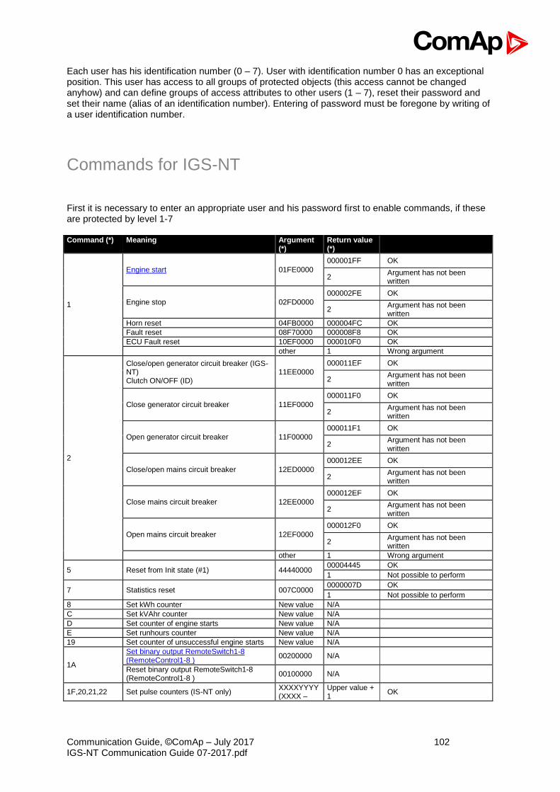
Communication Guide, ©ComAp – July 2017 102 IGS-NT Communication Guide 07-2017.pdf
Each user has his identification number (0 – 7). User with identification number 0 has an exceptional position. This user has access to all groups of protected objects (this access cannot be changed anyhow) and can define groups of access attributes to other users (1 – 7), reset their password and set their name (alias of an identification number). Entering of password must be foregone by writing of a user identification number.
Commands for IGS-NT
First it is necessary to enter an appropriate user and his password first to enable commands, if these are protected by level 1-7 Command (*) Meaning Argument
(*) Return value (*)
1
Engine start 01FE0000
000001FF OK
2 Argument has not been written
Engine stop 02FD0000
000002FE OK
2 Argument has not been written
Horn reset 04FB0000 000004FC OK
Fault reset 08F70000 000008F8 OK
ECU Fault reset 10EF0000 000010F0 OK
other 1 Wrong argument
2
Close/open generator circuit breaker (IGS-NT) Clutch ON/OFF (ID)
11EE0000
000011EF OK
2 Argument has not been written
Close generator circuit breaker 11EF0000
000011F0 OK
2 Argument has not been written
Open generator circuit breaker 11F00000
000011F1 OK
2 Argument has not been written
Close/open mains circuit breaker 12ED0000
000012EE OK
2 Argument has not been written
Close mains circuit breaker 12EE0000
000012EF OK
2 Argument has not been written
Open mains circuit breaker 12EF0000
000012F0 OK
2 Argument has not been written
other 1 Wrong argument
5 Reset from Init state (#1) 44440000 00004445 OK
1 Not possible to perform
7 Statistics reset 007C0000 0000007D OK
1 Not possible to perform
8 Set kWh counter New value N/A
C Set kVAhr counter New value N/A
D Set counter of engine starts New value N/A
E Set runhours counter New value N/A
19 Set counter of unsuccessful engine starts New value N/A
1A
Set binary output RemoteSwitch1-8 (RemoteControl1-8 )
00200000 N/A
Reset binary output RemoteSwitch1-8 (RemoteControl1-8 )
00100000 N/A
1F,20,21,22 Set pulse counters (IS-NT only) XXXXYYYY (XXXX –
Upper value + 1
OK
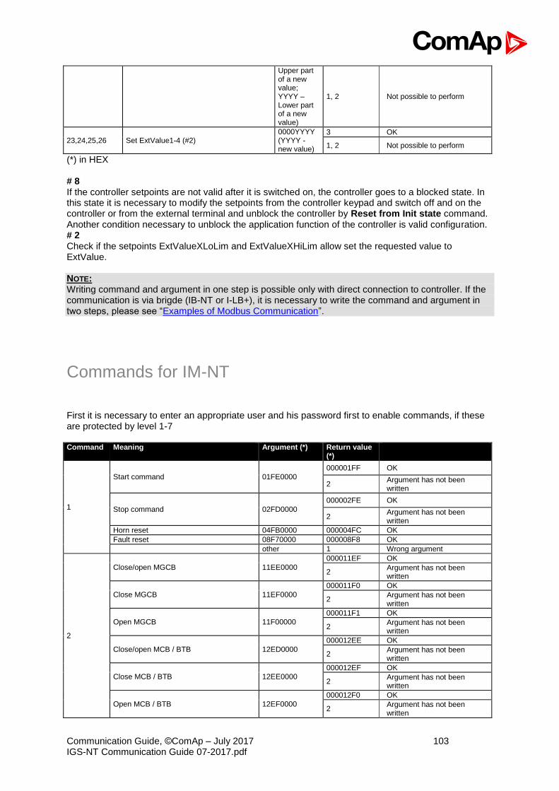
Communication Guide, ©ComAp – July 2017 103 IGS-NT Communication Guide 07-2017.pdf
Upper part of a new value; YYYY – Lower part of a new value)
1, 2 Not possible to perform
23,24,25,26 Set ExtValue1-4 (#2) 0000YYYY (YYYY - new value)
3 OK
1, 2 Not possible to perform
(*) in HEX # 8 If the controller setpoints are not valid after it is switched on, the controller goes to a blocked state. In this state it is necessary to modify the setpoints from the controller keypad and switch off and on the controller or from the external terminal and unblock the controller by Reset from Init state command. Another condition necessary to unblock the application function of the controller is valid configuration. # 2 Check if the setpoints ExtValueXLoLim and ExtValueXHiLim allow set the requested value to ExtValue. NOTE: Writing command and argument in one step is possible only with direct connection to controller. If the communication is via brigde (IB-NT or I-LB+), it is necessary to write the command and argument in two steps, please see “Examples of Modbus Communication”.
Commands for IM-NT
First it is necessary to enter an appropriate user and his password first to enable commands, if these are protected by level 1-7 Command Meaning Argument (*) Return value
(*)
1
Start command 01FE0000
000001FF OK
2 Argument has not been written
Stop command 02FD0000
000002FE OK
2 Argument has not been written
Horn reset 04FB0000 000004FC OK
Fault reset 08F70000 000008F8 OK
other 1 Wrong argument
2
Close/open MGCB 11EE0000
000011EF OK
2 Argument has not been written
Close MGCB 11EF0000
000011F0 OK
2 Argument has not been written
Open MGCB 11F00000
000011F1 OK
2 Argument has not been written
Close/open MCB / BTB 12ED0000
000012EE OK
2 Argument has not been written
Close MCB / BTB 12EE0000
000012EF OK
2 Argument has not been written
Open MCB / BTB 12EF0000
000012F0 OK
2 Argument has not been written
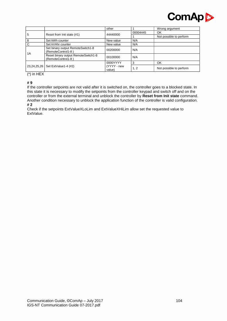
Communication Guide, ©ComAp – July 2017 104 IGS-NT Communication Guide 07-2017.pdf
other 1 Wrong argument
5 Reset from Init state (#1) 44440000 00004445 OK
1 Not possible to perform
8 Set kWh counter New value N/A
C Set kVAhr counter New value N/A
1A
Set binary output RemoteSwitch1-8 (RemoteControl1-8 )
00200000 N/A
Reset binary output RemoteSwitch1-8 (RemoteControl1-8 )
00100000 N/A
23,24,25,26 Set ExtValue1-4 (#2) 0000YYYY (YYYY - new value)
3 OK
1, 2 Not possible to perform
(*) in HEX # 9 If the controller setpoints are not valid after it is switched on, the controller goes to a blocked state. In this state it is necessary to modify the setpoints from the controller keypad and switch off and on the controller or from the external terminal and unblock the controller by Reset from Init state command. Another condition necessary to unblock the application function of the controller is valid configuration. # 2 Check if the setpoints ExtValueXLoLim and ExtValueXHiLim allow set the requested value to ExtValue.
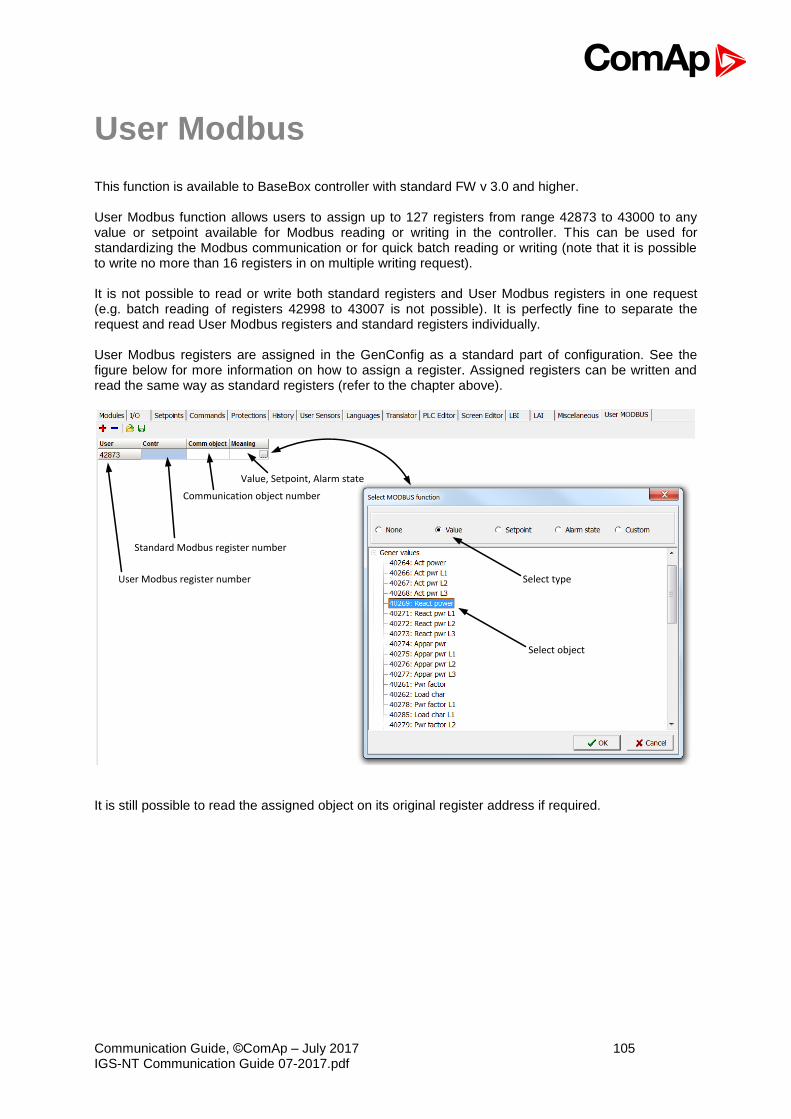
Communication Guide, ©ComAp – July 2017 105 IGS-NT Communication Guide 07-2017.pdf
User Modbus
This function is available to BaseBox controller with standard FW v 3.0 and higher. User Modbus function allows users to assign up to 127 registers from range 42873 to 43000 to any value or setpoint available for Modbus reading or writing in the controller. This can be used for standardizing the Modbus communication or for quick batch reading or writing (note that it is possible to write no more than 16 registers in on multiple writing request). It is not possible to read or write both standard registers and User Modbus registers in one request (e.g. batch reading of registers 42998 to 43007 is not possible). It is perfectly fine to separate the request and read User Modbus registers and standard registers individually. User Modbus registers are assigned in the GenConfig as a standard part of configuration. See the figure below for more information on how to assign a register. Assigned registers can be written and read the same way as standard registers (refer to the chapter above).
User Modbus register number
Standard Modbus register number
Communication object number
Value, Setpoint, Alarm state
Select type
Select object
It is still possible to read the assigned object on its original register address if required.
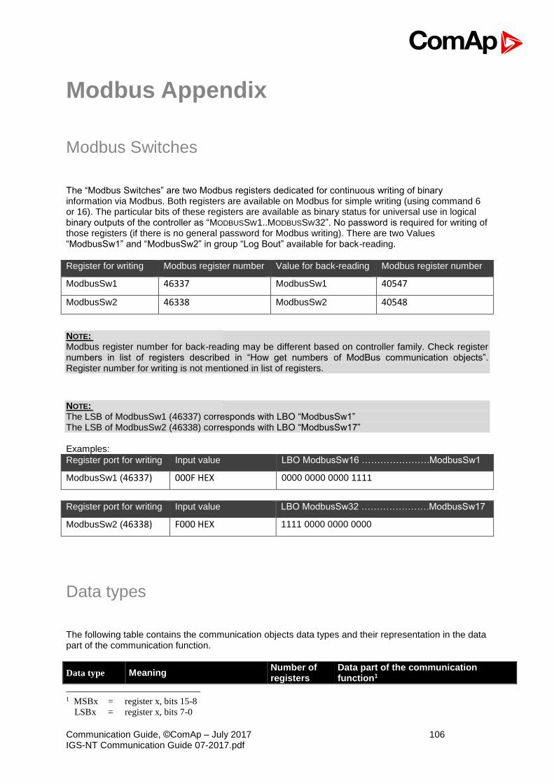
Communication Guide, ©ComAp – July 2017 106 IGS-NT Communication Guide 07-2017.pdf
Modbus Appendix
Modbus Switches
The “Modbus Switches” are two Modbus registers dedicated for continuous writing of binary information via Modbus. Both registers are available on Modbus for simple writing (using command 6 or 16). The particular bits of these registers are available as binary status for universal use in logical binary outputs of the controller as “MODBUSSW1..MODBUSSW32”. No password is required for writing of those registers (if there is no general password for Modbus writing). There are two Values “ModbusSw1” and “ModbusSw2” in group “Log Bout” available for back-reading.
Register for writing Modbus register number Value for back-reading Modbus register number
ModbusSw1 46337 ModbusSw1 40547
ModbusSw2 46338 ModbusSw2 40548
NOTE: Modbus register number for back-reading may be different based on controller family. Check register numbers in list of registers described in “How get numbers of ModBus communication objects”. Register number for writing is not mentioned in list of registers.
NOTE: The LSB of ModbusSw1 (46337) corresponds with LBO “ModbusSw1” The LSB of ModbusSw2 (46338) corresponds with LBO “ModbusSw17” Examples:
Register port for writing Input value LBO ModbusSw16 ………………….ModbusSw1
ModbusSw1 (46337) 000F HEX 0000 0000 0000 1111
Register port for writing Input value LBO ModbusSw32 ………………….ModbusSw17
ModbusSw2 (46338) F000 HEX 1111 0000 0000 0000
Data types
The following table contains the communication objects data types and their representation in the data part of the communication function.
Data type Meaning Number of registers
Data part of the communication function1
1 MSBx = register x, bits 15-8
LSBx = register x, bits 7-0

Communication Guide, ©ComAp – July 2017 107 IGS-NT Communication Guide 07-2017.pdf
Integer8 Signed integer – 8 bits 1 MSB1 = sign extension LSB1 LSB1 = comm. object value
Unsigned8 Unsigned integer – 8 bits 1 MSB1 = 0 LSB1 = comm. object value
Integer16 Signed integer – 16 bits 1 MSB1 = comm. object value, bits 15-8 LSB1 = comm. object value, bits 7-0
Unsigned16 Unsigned integer – 16 bits 1 MSB1 = comm. object value, bits 15-8 LSB1 = comm. object value, bits 7-0
Integer32 Signed integer – 32 bits 2
MSB1 = comm. object value, bits 31-24 LSB1 = comm. object value, bits 23-16 MSB2 = comm. object value, bits 15-8 LSB2 = comm. object value, bits 7-0
Unsigned32 Unsigned integer – 32 bits 2
MSB1 = comm. object value, bits 31-24 LSB1 = comm. object value, bits 23-16 MSB2 = comm. object value, bits 15-8 LSB2 = comm. object value, bits 7-0
Binary8 Binary number – 8 bits 1 MSB1 = 0 LSB1 = comm. object value
Binary16 Binary number – 16 bits 1 MSB1 = comm. object value, bits 15-8 LSB1 = comm. object value, bits 7-0
Binary32 Binary number – 32 bits 2
MSB1 = comm. object value, bits 31-24 LSB1 = comm. object value, bits 23-16 MSB2 = comm. object value, bits 15-8 LSB2 = comm. object value, bits 7-0
Char ASCII character 1 MSB1 = 0 LSB1 = comm. object value
List String list 1 MSB1 = 0 LSB1 = comm. object value
ShortStr ASCII string of max. length of 15
characters (zero terminated string) 8
MSB1 = 1. character of the string LSB1 = 2. character of the string MSB2 = 3. character of the string LSB2 = 4. character of the string …
LongStr ASCII string of max. length of 31
characters (zero terminated string) 16
MSB1 = 1. character of the string LSB1 = 2. character of the string MSB2 = 3. character of the string LSB2 = 4. character of the string …
Date Date 2
MSB1 = BCD(day) LSB1 = BCD(month) MSB2 = BCD(year) LSB2 = 0 example: MSB1 = 18 (HEX) LSB1 = 04 (HEX) MSB2 = 01 (HEX) LSB2 = 0
Date = 18.4.(20)01
Time Time 2
MSB1 = BCD(hour) LSB1 = BCD(minute) MSB2 = BCD(second) LSB2 = 0 example: MSB1 = 20 (HEX) LSB1 = 24 (HEX) MSB2 = 02 (HEX) LSB2 = 0
Time = 20:24:02

Communication Guide, ©ComAp – July 2017 108 IGS-NT Communication Guide 07-2017.pdf
Domain Field n bytes
C-declaratione: unsigned char x[n] n
MSB1 = x[0] LSB1 = x[1] MSB2 = x[2] LSB2 = x[3] … n is even number: MSBm-1 = x[n-2] LSBm = x[n-1] n is odd number: MSBm-1 = x[n-1] LSBm = 0
String String
(Zero terminated string)
depends on register number
string characters coding depends on chosen language (8bit coding, EUC)
Communication status
Communication object number:
24571
Operation:
Read only
Data type:
Binary32
Meaning:
Bit 0 Internal terminal in InteliSys does not work (0 for other controllers)
Bit 1 Invalid controller software (based on CRC).
Bit 2 Invalid controller configuration (based on CRC).
Bit 3 In the event history is present at least one unread record.
Bit 4 P type setpoints are invalid.
P type setpoints are representing the controller setpoints. Values of these setpoints can be set
from connected terminals. If these setpoints are invalid, the application functions are blocked.
Setpoints recovery is needed.
Bit 5 R type setpoints are invalid.
R type setpoints are representing the data, that is only initialized from connected terminals, but
its updating is made by the controller itself (e.g. statistic or time and date). If these setpoints
are invalid, their change from the controller is blocked. Setpoints recovery is needed.
Bit 6 The event history was cleared.
Bit 7 The event history was filled up at least once.
Bit 8 P type setpoint change occurred (reading resets this bit).
Bit 9 R type setpoint change occurred (reading resets this bit).
Bit 10 Controller type – see the table below.
Bit 11 Alarm list not empty.
Bit 12 Alarm list change (reading resets this bit).
Bit 13 New item added into alarm list (reading resets this bit).
Bit 14 Internal controller terminal is locked up for setpoint change.
Bit 15 Invalid configuration format.
Bit 16 Diagnostic codes change (reading resets this bit, only for IL-NT /ID controllers).
Bits 20 Controller type (*)
Bit 21-17 Reserve (= 0)
Bits 22-21 Password level for Setpoints and Commands write (only for IL-NT /ID controllers).
Bit 23 Controller was initiated.
Bits 28-24 Communication module version.
Bits 29 Remote terminal is connected.
Bits 30 Controller type – see the table below.
Bits 31 Reserve (= 0)
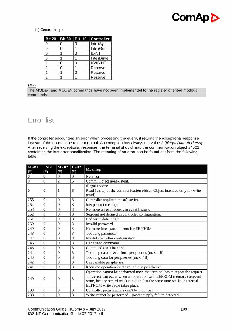
Communication Guide, ©ComAp – July 2017 109 IGS-NT Communication Guide 07-2017.pdf
(*) Controller type
Bit 20 Bit 30 Bit 10 Controller
0 0 0 InteliSys
0 0 1 InteliGen
0 1 0 IL-NT
0 1 1 InteliDrive
1 0 0 IG/IS-NT
1 0 1 Reserve
1 1 0 Reserve
1 1 1 Reserve
Hint: The MODE< and MODE> commands have not been implemented to the register oriented modbus commands.
Error list
If the controller encounters an error when processing the query, it returns the exceptional response instead of the normal one to the terminal. An exception has always the value 2 (Illegal Data Address). After receiving the exceptional response, the terminal should read the communication object 24523 containing the last error specification. The meaning of an error can be found out from the following table.
MSB1
(*)
LSB1
(*)
MSB2
(*)
LSB2
(*) Meaning
0 0 0 0 No error.
0 0 2 6 Comm. Object nonexistent.
0 0 1 6
Illegal access:
Read (write) of the communication object. Object intended only for write
(read).
255 0 0 8 Controller application isn’t active
254 0 0 8 Inexpectant message
253 0 0 8 No more unread records in event history.
252 0 0 8 Setpoint not defined in controller configuration.
251 0 0 8 Bad write data length.
250 0 0 8 Invalid password.
249 0 0 8 No more free space in front for EEPROM
248 0 0 8 Too long parameter
247 0 0 8 Invalid controller configuration.
246 0 0 8 Undefined command
245 0 0 8 Command can’t be done
244 0 0 8 Too long data answer form peripheries (max. 4B)
243 0 0 8 Too long data for peripheries (max. 4B)
242 0 0 8 Unavailable peripheries
241 0 0 8 Required operation isn’t available in peripheries
240 0 0 8
Operation cannot be performed now, the terminal has to repeat the request.
This error can occur when an operation with EEPROM memory (setpoint
write, history record read) is required at the same time while an internal
EEPROM write cycle takes place.
239 0 0 8 Controller programming can’t be carry out
238 0 0 8 Write cannot be performed – power supply failure detected.
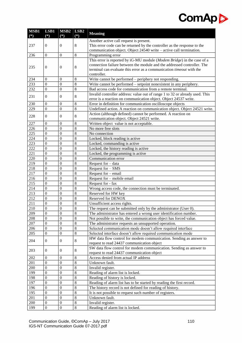
Communication Guide, ©ComAp – July 2017 110 IGS-NT Communication Guide 07-2017.pdf
MSB1
(*)
LSB1
(*)
MSB2
(*)
LSB2
(*) Meaning
237 0 0 8
Another active call request is present.
This error code can be returned by the controller as the response to the
communication object. Object 24540 write – active call termination.
236 0 0 8 Programming error
235 0 0 8
This error is reported by iG-MU module (Modem Bridge) in the case of a
connection failure between the module and the addressed controller. The
terminal can evaluate this error as a communication timeout with the
controller.
234 0 0 8 Write cannot be performed – periphery not responding.
233 0 0 8 Write cannot be performed – setpoint nonexistent in any periphery.
232 0 0 8 Bad access code for communication from a remote terminal.
231 0 0 8 Invalid controller address: value out of range 1 to 32 or already used. This
error is a reaction on communication object. Object 24537 write.
230 0 0 8 Error in definition for communication oscilloscope objects
229 0 0 8 Undefined action. A reaction on communication object. Object 24521 write.
228 0 0 8 Action (although defined) cannot be performed. A reaction on
communication object. Object 24521 write.
227 0 0 8 Written object value is not acceptable.
226 0 0 8 No more free slots
225 0 0 8 No connection
224 0 0 8 Locked, block reading is active
223 0 0 8 Locked, commanding is active
222 0 0 8 Locked, the history reading is active
221 0 0 8 Locked, the programming is active
220 0 0 8 Communication error
219 0 0 8 Request for – data
218 0 0 8 Request for – SMS
217 0 0 8 Request for – email
216 0 0 8 Request for – mobile email
215 0 0 8 Request for - fax
214 0 0 8 Wrong access code, the connection must be terminated.
213 0 0 8 Reserved for HW key
212 0 0 8 Reserved for DENOX
211 0 0 8 Unsufficient access rights.
210 0 0 8 The request can be submitted only by the administrator (User 0).
209 0 0 8 The administrator has entered a wrong user identification number.
208 0 0 8 Not possible to write, the communication object has forced value.
207 0 0 8 The administrator requests an unsupported operation.
206 0 0 8 Selected communication mode doesn’t allow required interface
205 0 0 8 Selected interface doesn’t allow required communication mode
204 0 0 8 HW data flow control for modem communication. Sending as answer to
request to read 24437 communication object
203 0 0 8 SW data flow control for modem communication. Sending as answer to
request to read 24437 communication object
202 0 0 8 Access denied from actual IP address
201 0 0 8 Unknown fault.
200 0 0 8 Invalid register.
199 0 0 8 Reading of alarm list is locked.
198 0 0 8 Reading of history is locked.
197 0 0 8 Reading of alarm list has to be started by reading the first record.
196 0 0 8 The history record is not defined for reading of history.
195 0 0 8 It is not possible to request such number of registers.
201 0 0 8 Unknown fault.
200 0 0 8 Invalid register.
199 0 0 8 Reading of alarm list is locked.

Communication Guide, ©ComAp – July 2017 111 IGS-NT Communication Guide 07-2017.pdf
MSB1
(*)
LSB1
(*)
MSB2
(*)
LSB2
(*) Meaning
198 0 0 8 Reading of history is locked.
(*) in DEC dedicated for Internet Bridge
Note: ComAp believes that all information provided herein is correct and reliable and reserves the right to update at any time. ComAp does not assume any responsibility for its use unless otherwise expressly undertaken.
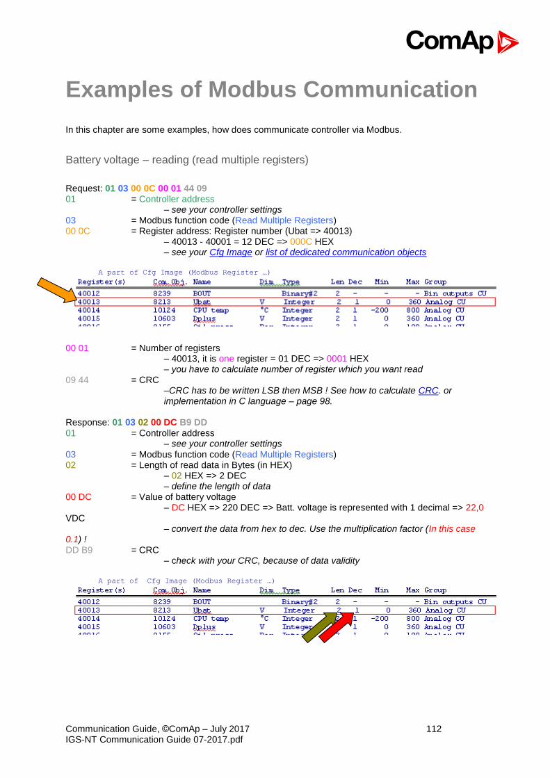
Communication Guide, ©ComAp – July 2017 112 IGS-NT Communication Guide 07-2017.pdf
Examples of Modbus Communication
In this chapter are some examples, how does communicate controller via Modbus.
Battery voltage – reading (read multiple registers)
Request: 01 03 00 0C 00 01 44 09 01 = Controller address
– see your controller settings 03 = Modbus function code (Read Multiple Registers) 00 0C = Register address: Register number (Ubat => 40013)
– 40013 - 40001 = 12 DEC => 000C HEX – see your Cfg Image or list of dedicated communication objects
A part of Cfg Image (Modbus Register …)
00 01 = Number of registers
– 40013, it is one register = 01 DEC => 0001 HEX – you have to calculate number of register which you want read
09 44 = CRC –CRC has to be written LSB then MSB ! See how to calculate CRC. or implementation in C language – page 98.
Response: 01 03 02 00 DC B9 DD 01 = Controller address
– see your controller settings 03 = Modbus function code (Read Multiple Registers) 02 = Length of read data in Bytes (in HEX) – 02 HEX => 2 DEC – define the length of data 00 DC = Value of battery voltage – DC HEX => 220 DEC => Batt. voltage is represented with 1 decimal => 22,0 VDC – convert the data from hex to dec. Use the multiplication factor (In this case 0.1) ! DD B9 = CRC – check with your CRC, because of data validity
A part of Cfg Image (Modbus Register …)

Communication Guide, ©ComAp – July 2017 113 IGS-NT Communication Guide 07-2017.pdf
Values (Oil press, Water temp, Fuel level) – reading
Request: 01 03 00 0F 00 03 35 C8 01 = Controller address 03 = Modbus function code (Read Multiple Registers) 00 0F = Register address: Register number (40016) – 40001 = 15 DEC => 0F HEX 00 03 = Number of registers (40016 – Oil press, 40017 – Water temp, 40018 – Fuel level)
= 3 DEC = > 03 HEX C8 35 = CRC (write LSB MSB !)
A part of Cfg Image (Modbus Register …)
Response: 01 03 06 00 27 00 2E 00 2B 35 64 01 = Controller address 03 = Modbus function code (Read Multiple Registers) 06 = Length of read data in Bytes (in HEX) 00 27 = 27 HEX => 39 DEC => 3,9 Bar (Oil pressure is represented with 1 decimal in Bars) 00 2E = 2E HEX => 46 DEC => 46°C (Water temperature is represented with 0 decimals in °C) 00 2B = 2B HEX => 43 DEC => 43% (Fuel level is represented with 0 decimals in %) 64 35 = CRC
Binary input - reading
Request: 01 03 00 02 00 01 25 CA 01 = Controller address 03 = Modbus function code (Read Multiple Registers) 00 02 = Register address: Register number (40003) – 40001 = 02 DEC => 02 HEX 00 01 = Number of registers (40003) = 01 DEC => 01 HEX CA 25 = CRC (write LSB MSB !) Response: 01 03 02 00 0A 38 43 01 = Controller address 03 = Modbus function code (Read Multiple Registers) 02 = Length of read data in Bytes (in HEX) 00 0A = Object data value (Binary input = 00000000000001010 i.e. BI2 and BI4 are set)* 43 38 = CRC
* Table of binary inputs (BI) BI16 BI15 BI14 BI13 BI12 BI11 BI10 BI9 BI8 BI7 BI6 BI5 BI4 BI3 BI2 BI1
0 0 0 A 0 0 0 0 0 0 0 0 0 0 0 0 1 0 1 0
Password decode - reading
Request: 01 03 00 A0 00 02 C4 29 01 = Controller address 03 = Modbus function code (Read Multiple Registers) 00 A0 = Register address: Register number (40161) – 40001 = 160 DEC => A0 HEX

Communication Guide, ©ComAp – July 2017 114 IGS-NT Communication Guide 07-2017.pdf
00 02 = Number of registers (40161 and 40162) = 02 DEC => 02 HEX 29 C4 = CRC (write LSB MSB !) Response: 01 03 04 68 73 90 00 7B 88 01 = Controller address 03 = Modbus function code (Read Multiple Registers) 04 = Length of read data in Bytes (in HEX) 68 73 90 00 = 68739000 HEX => 1752403968 DEC = > password decode is 1752403968 88 7B = CRC
Gen-set name - reading
Request: 01 03 0B B8 00 08 C6 0D 01 = Controller address 03 = Modbus function code (Read Multiple Registers) 0B B8 = Register address: Register number (43001) – 40001 = 3000 DEC => BB8 HEX 00 08 = Number of registers (43001 - 43008) = 08 DEC => 08 HEX 0D C6 = CRC (write LSB MSB !) Response: 01 03 10 49 47 53 2D 4E 54 00 00 00 00 00 00 00 00 00 00 D7 6A 01 = Controller address 03 = Modbus function code (Read Multiple Registers) 10 = Length of read data in Bytes (in HEX) 49 47 = Object data value (IG) 53 2D = Object data value (S-) 4E 54 = Object data value (NT) 00 00 = Object data value (_ _) 00 00 = Object data value (_ _) 00 00 = Object data value (_ _) 00 00 = Object data value (_ _) 00 00 = Object data value (_ _) =.> gen-set name is IGS-NT 6A D7 = CRC
Engine state - reading
Request: 01 03 00 A2 00 01 25 E8 01 = Controller address 03 = Modbus function code (Read Multiple Registers) 00 A2 = Register address: Register number (40163) – 40001 = 162 DEC => A2 HEX 00 01 = Number of registers (40163) E8 25 = CRC (write LSB MSB !) Response: 01 03 02 00 02 39 85 01 = Controller address 03 = Modbus function code (Read Multiple Registers) 02 = Length of read data in Bytes (in HEX) 00 02 = Object data value – see the List#1 in the Cfg Image => (NotReady) 85 39 = CRC
A part of Cfg Image (Modbus Register …)
A part of Cfg Image (Modbus Register …)
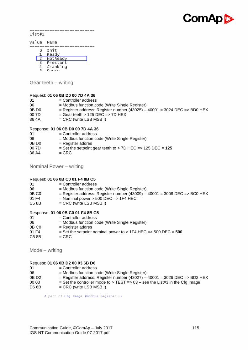
Communication Guide, ©ComAp – July 2017 115 IGS-NT Communication Guide 07-2017.pdf
Gear teeth – writing
Request: 01 06 0B D0 00 7D 4A 36 01 = Controller address 06 = Modbus function code (Write Single Register) 0B D0 = Register address: Register number (43025) – 40001 = 3024 DEC => BD0 HEX 00 7D = Gear teeth > 125 DEC => 7D HEX 36 4A = CRC (write LSB MSB !) Response: 01 06 0B D0 00 7D 4A 36 01 = Controller address 06 = Modbus function code (Write Single Register) 0B D0 = Register addres 00 7D = Set the setpoint gear teeth to > 7D HEC => 125 DEC = 125 36 A4 = CRC
Nominal Power – writing
Request: 01 06 0B C0 01 F4 8B C5 01 = Controller address 06 = Modbus function code (Write Single Register) 0B C0 = Register address: Register number (43009) – 40001 = 3008 DEC => BC0 HEX 01 F4 = Nominal power > 500 DEC => 1F4 HEC C5 8B = CRC (write LSB MSB !) Response: 01 06 0B C0 01 F4 8B C5 01 = Controller address 06 = Modbus function code (Write Single Register) 0B C0 = Register addres 01 F4 = Set the setpoint nominal power to > 1F4 HEC => 500 DEC = 500 C5 8B = CRC
Mode – writing
Request: 01 06 0B D2 00 03 6B D6 01 = Controller address 06 = Modbus function code (Write Single Register) 0B D2 = Register address: Register number (43027) – 40001 = 3026 DEC => BD2 HEX 00 03 = Set the controller mode to > TEST => 03 – see the List#3 in the Cfg Image D6 6B = CRC (write LSB MSB !)
A part of Cfg Image (Modbus Register …)

Communication Guide, ©ComAp – July 2017 116 IGS-NT Communication Guide 07-2017.pdf
Response: 01 06 0B D2 00 03 6B D6 01 = Controller address 06 = Modbus function code (Write Single Register) 0B D2 = Register addres 00 03 = Object data value > TEST D6 6B = CRC
Reset / Confirm Alarm
Request: 01 10 18 D6 00 03 06 08 F7 00 00 00 01 49 CB 01 = controller address 10 = Modbus command 18 D6 = Register address: Object for engine commands (46359) – 40001 = 6358 DEC
=> 18D6 HEX 00 03 = number of Modbus registers 06 = data length in bytes (08F70000+0001) 08F70000 = argument for Fault reset (page 102) 0001 = command number (page 102) CB 49 = CRC (write LSB MSB !)
A part of dedicated communication objects table
Registers (*) Register
addresses (*) Number of registers
Access Data type Meaning
46359 – 46360 6358 – 6359 2 read/write Unsigned32 For writing:command argument For reading: command release value (# 3)
46361 6360 1 write Unsigned16 Command (# 3)
A part of list of commands
Command Meaning Argument
(*) Return value (*)
1
Engine start 01FE0000 000001FF OK
2 Argument has not been written
Engine stop
02FD0000 000002FE OK
2 Argument has not been written
Horn reset 04FB0000 000004FC OK
Fault reset 08F70000 000008F8 OK
ECU Fault reset 10EF0000 000010F0 OK other 1 Wrong argument
Response: 01,10,18,D6,00,03,67,50 01 = Controller address 10 = Modbus command 18 D6 = Register addres 00 03 = Release value, number of written Modbus registers 50 67 = CRC

Communication Guide, ©ComAp – July 2017 117 IGS-NT Communication Guide 07-2017.pdf
Remote Switch 1 – Set (Remote Control 1)
Request: 01 10 18 D6 00 03 06 00 20 00 00 00 1A 7C 9A 01 = controller address 10 = Modbus command 18 D6 = Register address: Object for engine commands (46359) – 40001 = 6358 DEC
=> 18D6 HEX 00 03 = number of Modbus registers 06 = data length in bytes (08F70000+001A) 00200000 = argument for RemoteSwitch1-8 (page 102) 001A = command number (page 102), command = 26 DEC = 001A HEX 9A 7C = CRC (write LSB MSB !) Response: 01 10 18 D6 00 03 67 50 01 = Controller address 10 = Modbus command 18 D6 = Register addres 00 03 = Release value, number of written Modbus registers 50 67 = CRC Request: 01 10 18 D6 00 03 06 00 10 00 00 00 1A 3C E9 – Remote Switch 1 – Off Request: 01 10 18 D6 00 03 06 00 20 00 01 00 1A 8C 9A – Remote Switch 2 – Set
Table of arguments
RemoteSwitch 1 2 3 4 5 6 7 8 Set / On 00200000 00200001 00200002 00200003 00200004 00200005 00200006 00200007
Off 00100000 00100001 00100002 00100003 00100004 00100005 00100006 00100007
External Value1 – writing
Request: 01 10 18 D6 00 03 06 00 02 00 24 00 23 04 84 01 = controller address 10 = Modbus command 18 D6 = Register address: Object for engine commands (46359) – 40001 = 6358 DEC
=> 18D6 HEX 00 03 = number of Modbus registers 06 = data length in bytes (00020024+0023) 00020024 = argument for Set ExtValue 1-4 (page 102) (value 36DEC = 0024HEX) 0023 = command number (page 102), command = 35 DEC = 0023 HEX 84 04 = CRC (write LSB MSB !) Response: 01 10 18 D6 00 03 67 50 01 = Controller address 10 = Modbus command 18 D6 = Register addres 00 03 = Release value, number of written Modbus registers 50 67 = CRC NOTE: Writing External Value in one step is possible only with direct connection to controller. If communication brigde (IB-NT or I-LB+) is used, it is necessary to write the command and argument in two steps.

Communication Guide, ©ComAp – July 2017 118 IGS-NT Communication Guide 07-2017.pdf
User & Password – in two steps
Request: 01 06 18 DA 00 00 AE 91 01 = controller address 06 = Modbus function code (Write Single Register) 18 DA = Register address: Object for user identification (46363) – 40001 = 6362 DEC
=> 18DA HEX 00 00 = ID of user; Administrator = 00 => 0000 91 AE = CRC (write LSB MSB !)
A part of dedicated communication objects table
Registers (*) Register
addresses (*) Number of registers
Access Data type Meaning
46361 6360 1 write Unsigned16 Command (# 3) 46362 6361 1 Reserved (register not implemented)
46363 6362 1 read/write Unsigned8 User identification number (# 4)
46364 6363 1 write Unsigned16 Entering of password for writing (# 4)
46365 6364 1 Reserved (register not implemented) 46366 – 46490 6365 – 6489 125 read Domain Values multipacket(#8)
Response: 01 06 18 DA 00 00 AE 91 01 = Controller address 06 = Modbus command 18 DA = Register addres 00 00 = Release value 91 AE = CRC Request: 01 06 18 DB 00 00 FF 51 01 = controller address 06 = Modbus function code (Write Single Register) 18 DB = Register address: Object for entering password (46364) – 40001 = 6363 DEC
=> 18DB HEX 00 00 = Password = 00 => 0000 51 FF = CRC (write LSB MSB !) Response: 01 06 18 DB 00 00 FF 51 01 = Controller address 06 = Modbus command 18 DB = Register addres 00 00 = Release value 51 FF = CRC Hint: Before entering the password for writing it is necessary to define user identification number. It is recommended to enter user identification number and password simultaneously. Entered password stays valid 5 minutes after the last successful writing.

Communication Guide, ©ComAp – July 2017 119 IGS-NT Communication Guide 07-2017.pdf
User & Password – in one step
Request: 01 10 18 DA 00 02 04 00 00 00 00 D4 8C 01 = controller address 10 = Modbus command (Write Multiple Register) 18 DA = Register address: Object (46363) – 40001 = 6362 DEC => 18DA HEX 00 02 = number of Modbus registers (user & password) 04 = data length in bytes (00 00 00 00) 00 00 00 00 = User identification “00 00” & password “00 00” 8C D4 = CRC (write LSB MSB !)
A part of dedicated communication objects table
Registers (*) Register
addresses (*) Number of registers
Access Data type Meaning
46361 6360 1 write Unsigned16 Command (# 3) 46362 6361 1 Reserved (register not implemented)
46363 6362 1 read/write Unsigned8 User identification number (# 4)
46364 6363 1 write Unsigned16 Entering of password for writing (# 4)
46365 6364 1 Reserved (register not implemented) 46366 – 46490 6365 – 6489 125 read Domain Values multipacket(#8)
Response: 01,10,18,DA,00,02,66,93 01 = Controller address 10 = Modbus command 18 DA = Register addres 00 02 = number of written Modbus registers 93 66 = CRC
Start the engine – in one step
To start the engine it is necessary to enter an appropriate user and his password first to enable commands, if these are protected by level 1-7. Request: 01 10 18 D6 00 03 06 01 FE 00 00 00 01 95 53 01 = controller address 10 = Modbus command (Write Multiple Register) 18D6 = 6538 object for engine commands (46359) – 40001 = 6358 DEC => 18D6 HEX 0003 = number of Modbus registers 06 = data length in bytes (01FE0000+0001) 01FE0000 = argument for Engine start (page 102) 0001 = command number (page 102) 53 95 = CRC (write LSB MSB !) Response: 01 10 18 D6 00 03 67 50 01 = Controller address 10 = Modbus function code (Read Multiple Registers) 18 D6 = Register addres 00 03 = Release value, number of written Modbus registers 50 67 = CRC NOTE: Starting the engine in one step is possible only with direct connection to controller. If communication brigde (IB-NT or I-LB+) is used, it is necessary to write the command and argument in two steps, please see “Start the engine – in two steps”.
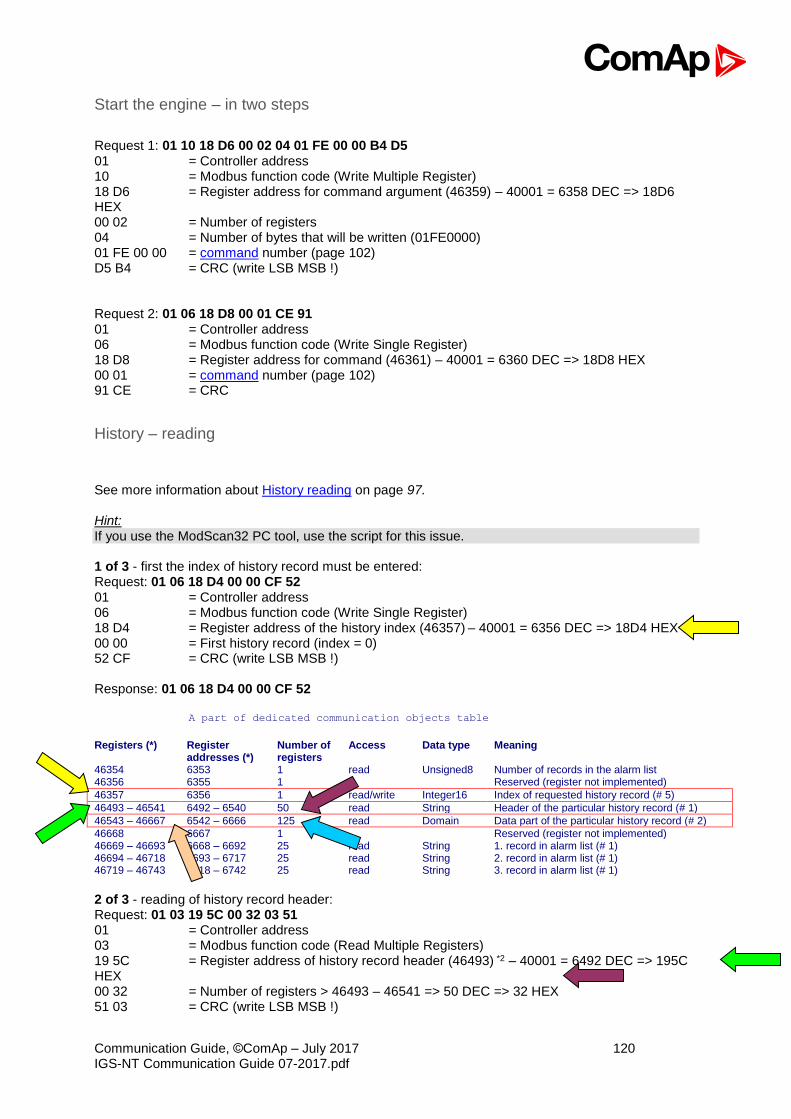
Communication Guide, ©ComAp – July 2017 120 IGS-NT Communication Guide 07-2017.pdf
Start the engine – in two steps
Request 1: 01 10 18 D6 00 02 04 01 FE 00 00 B4 D5 01 = Controller address 10 = Modbus function code (Write Multiple Register) 18 D6 = Register address for command argument (46359) – 40001 = 6358 DEC => 18D6 HEX 00 02 = Number of registers 04 = Number of bytes that will be written (01FE0000) 01 FE 00 00 = command number (page 102) D5 B4 = CRC (write LSB MSB !) Request 2: 01 06 18 D8 00 01 CE 91 01 = Controller address 06 = Modbus function code (Write Single Register) 18 D8 = Register address for command (46361) – 40001 = 6360 DEC => 18D8 HEX 00 01 = command number (page 102) 91 CE = CRC
History – reading
See more information about History reading on page 97. Hint: If you use the ModScan32 PC tool, use the script for this issue. 1 of 3 - first the index of history record must be entered: Request: 01 06 18 D4 00 00 CF 52 01 = Controller address 06 = Modbus function code (Write Single Register) 18 D4 = Register address of the history index (46357) – 40001 = 6356 DEC => 18D4 HEX 00 00 = First history record (index = 0) 52 CF = CRC (write LSB MSB !) Response: 01 06 18 D4 00 00 CF 52
A part of dedicated communication objects table
Registers (*) Register
addresses (*) Number of registers
Access Data type Meaning
46354 6353 1 read Unsigned8 Number of records in the alarm list 46356 6355 1 Reserved (register not implemented)
46357 6356 1 read/write Integer16 Index of requested history record (# 5)
46493 – 46541 6492 – 6540 50 read String Header of the particular history record (# 1)
46543 – 46667 6542 – 6666 125 read Domain Data part of the particular history record (# 2)
46668 6667 1 Reserved (register not implemented) 46669 – 46693 6668 – 6692 25 read String 1. record in alarm list (# 1) 46694 – 46718 6693 – 6717 25 read String 2. record in alarm list (# 1) 46719 – 46743 6718 – 6742 25 read String 3. record in alarm list (# 1)
2 of 3 - reading of history record header: Request: 01 03 19 5C 00 32 03 51 01 = Controller address 03 = Modbus function code (Read Multiple Registers) 19 5C = Register address of history record header (46493) *2 – 40001 = 6492 DEC => 195C HEX 00 32 = Number of registers > 46493 – 46541 => 50 DEC => 32 HEX 51 03 = CRC (write LSB MSB !)

Communication Guide, ©ComAp – July 2017 121 IGS-NT Communication Guide 07-2017.pdf
Response: 01 03 64 4D 43 42 20 63 6C 6F 73 65 64 20 20 20 20 20 20 20 20 20 20 30 33 2F 30 39 2F 32 30 30 38 20 20 31 35 3A 34 34 3A 35 37 2E 39 00 … 00 00 0E E0 01 = Controller address 03 = Modbus function code (Read Multiple Registers) 64 = Length of read data in Bytes (in HEX) 4D .. 39 … = Object data value > 1.record in alarmlist is MCB closed 03.09.2008 15:44:57.9 E0 0E = CRC 3 of 3 - reading of the data part of history record: Request: 01 03 19 8E 00 7D E2 9C 01 = Controller address 03 = Modbus function code (Read Multiple Registers) 19 8E = Register address of history record header (46543) – 40001 = 6542 DEC => 198E HEX
00 7D = Number of registers > 46542 – 46667 => 125 DEC => 7D HEX 9C E2 = CRC (write LSB MSB !)
Response: 01 03 FA 00 00 00 00 00 00 00 20 00 … 00 00 F4 01 FD 00 FD 00 FD 00 00 00 00 00 00 00 00 64 20 00 00 00 00 64 00 D8 00 55 01 00 00 A1 00 7A 00 64 00 0A 00 18 00 00 00 00 … 00 00 20 3B 01 = Controller address 03 = Modbus function code (Read Multiple Registers) FA = Length of read data in Bytes (in HEX) 00 .. 00 = Object data value > for reading this data see table 7 History Record in Communication object description (in PC tool -> File –> Generate Cfg Image –> Generate Cfg Image (Comm. Objects …)) 3B 20 = CRC
AlarmList reading
See more information about AlarmList reading on page 95. Request: 01 03 1A 0C 00 19 43 B1 01 = Controller address 03 = Modbus function code (Read Multiple Registers) 1A 0C = Register address: Register number (46669) – 40001 = 6668 DEC => 1A0C HEX 00 19 = Number of registers > 46669 – 46693 => 25 DEC => 19 HEX B1 43 = CRC (write LSB MSB !)
A part of dedicated communication objects table
Registers (*) Register
addresses (*) Number of registers
Access Data type Meaning
46354 6353 1 read Unsigned8 Number of records in the alarm list 46357 6356 1 read/write Integer16 Index of requested history record (# 5) 46364 6363 1 write Unsigned16 Entering of password for writing (
# 4)
46542 6541 1 Reserved (register not implemented) 46668 6667 1 Reserved (register not implemented)
46669 – 46693 6668 – 6692 25 read String 1. record in alarm list (# 1)
46694 – 46718 6693 – 6717 25 read String 2. record in alarm list (# 1) 46719 – 46743 6718 – 6742 25 read String 3. record in alarm list (# 1)
Response: 01 03 32 2A 53 64 20 53 44 20 31 32 … 00 00 18 F5 01 = Controller address 03 = Modbus function code (Read Multiple Registers) 32 = Length of read data in Bytes (in HEX) 2A 53 = Object data value (* S) 64 20 = Object data value (d _)

Communication Guide, ©ComAp – July 2017 122 IGS-NT Communication Guide 07-2017.pdf
53 44 = Object data value (S D) 20 31 = Object data value (_ 1) 32 00 … = Object data value (2) = > 1.record in alarmlist is *Sd SD 12 (inactive, not accepted) F5 18 = CRC Response: 01 03 32 21 2A 53 64 20 53 44 20 31 32 00 00 … 00 00 89 38 01 = Controller address 03 = Modbus function code (Read Multiple Registers) 32 = Length of read data in Bytes (in HEX) 21 2A = Object data value (! *) 53 64 = Object data value (S d) 20 53 = Object data value (_ S) 44 20 = Object data value (D _) 31 32 … = Object data value (1 2) = > 1.record in alarmlist is !*Sd SD 12 (active, not accepted) 38 89 = CRC
Change the communication language (only String type data) Write to the communication object 6350 the index of language to be used.
A part of dedicated communication objects table Registers (*) Register
addresses (*) Number of registers
Access Data type Meaning
46349 – 46350 6348 – 6349 2 read/write Date Actual date
46351 6350 1 read/write Unsigned8 Language index selected for displaying of texts specified by data type String (# 7)
46352 – 4653 6351 – 6352 2 read Domain Code of the last communication fault See Error list
46354 6353 1 read Unsigned8 Number of records in the alarm list 46349 – 46350 6348 – 6349 2 read/write Date Actual date 46351 6350 1 read/write Unsigned8 Language index selected for displaying of texts
specified by data type String (# 7)
Request: 01 06 18 CE 00 01 2F 55 01 = Controller address 06 = Modbus function code (Write Single Register) 18 CE = Register address: Register number (46351) – 40001 = 6350 DEC => 18CE HEX 00 01 = Set the language index to > 1 55 2F = CRC (write LSB MSB !)
Response: 01 06 18 CE 00 00 EE 95 01 = Controller address 06 = Modbus function code (Read Multiple Registers) 18 CE = Register address 00 01 = Language index set to > 1 55 2F = CRC