Embed Size (px)
Citation preview
Copyright © 2008 ComAp a.s.
ComAp a.s.
Kundratka 2359/17, 180 00 Prague 8, Czech Republic Tel: +420 246 012 111, Fax: +420 266 316 647
E-mail: [email protected], www.comap.cz
REFERENCE GUIDE
GenConfig
Configuration Tool for Gen-set controllers
To be used with ComAp controllers from following product lines:
InteliGen-NT, InteliSys-NT, InteliMains-NT
SW version 3.0, June 2013
GenConfig, SW version 3.0, ©ComAp – June 2013 2 Genconfig-3.0-Reference guide.pdf
Table of contents
Table of contents ..................................................................................................................................... 2 Document information ............................................................................................................................. 4
Clarification of notation ........................................................................................................................ 4 General guidelines ................................................................................................................................... 5
What is GenConfig? ............................................................................................................................. 5 Installation ............................................................................................................................................ 5
GenConfig directories....................................................................................................................... 6 PC Hardware requirements .............................................................................................................. 6
Basic and advanced modes ................................................................................................................. 7 Archive versus Configuration ............................................................................................................... 7 How to check GenConfig version? ...................................................................................................... 8
Working with GenConfig .......................................................................................................................... 9 Typical workflow ................................................................................................................................. 10 Open archive from disk ...................................................................................................................... 11 Read archive from controller .............................................................................................................. 11 Write configuration to the controller ................................................................................................... 11 Save archive to disk ........................................................................................................................... 12 Configuration import ........................................................................................................................... 12
Archive compatibility overview ....................................................................................................... 12 Controller firmware upgrade .............................................................................................................. 13
Importing new firmware .................................................................................................................. 13 Firmware upgrade (default configuration) ...................................................................................... 14 Firmware upgrade (existing configuration) ..................................................................................... 14 Cloning ........................................................................................................................................... 16 Programming firmware into a non-responding controller ............................................................... 17
Controller configuration ......................................................................................................................... 18 Essential configuration steps ............................................................................................................. 18 Optional configuration steps .............................................................................................................. 19 Configuration locking ......................................................................................................................... 19 Modules.............................................................................................................................................. 20
Controller ........................................................................................................................................ 22 ECU ................................................................................................................................................ 23 Extension modules ......................................................................................................................... 25 Shared virtual extension modules .................................................................................................. 26
Inputs and Outputs ............................................................................................................................. 29 Binary inputs ................................................................................................................................... 29 Binary outputs ................................................................................................................................ 31 Analog inputs .................................................................................................................................. 33 Analog outputs ............................................................................................................................... 37
Setpoints ............................................................................................................................................ 42 Adjusting setpoints ......................................................................................................................... 42 Access groups and rights ............................................................................................................... 43 Setpoint value forcing ..................................................................................................................... 44 Timer settings ................................................................................................................................. 45
Commands ......................................................................................................................................... 47 Universal analog protections ............................................................................................................. 48 History ................................................................................................................................................ 53 User sensors ...................................................................................................................................... 54 Languages and Translator ................................................................................................................. 56
Create language ............................................................................................................................. 56 Translating the texts ....................................................................................................................... 57
PLC Editor .......................................................................................................................................... 60 Working with the editor ................................................................................................................... 60 PLC Editor toolbar .......................................................................................................................... 69 PLC blocks ..................................................................................................................................... 70
GenConfig, SW version 3.0, ©ComAp – June 2013 3 Genconfig-3.0-Reference guide.pdf
InteliVision Screen Editor ................................................................................................................... 71 Logical binary inputs .......................................................................................................................... 72 Logical analog inputs ......................................................................................................................... 73 Other configuration items ................................................................................................................... 74 User MODBUS ................................................................................................................................... 75
Menu description ................................................................................................................................... 76 File menu ........................................................................................................................................... 76
Open archive from disk .................................................................................................................. 76 Save archive to disk ....................................................................................................................... 76 Recently saved archives ................................................................................................................ 76 Close archive .................................................................................................................................. 76 Read archive from controller .......................................................................................................... 76 Write configuration to the controller ............................................................................................... 77 Consistency check ......................................................................................................................... 77 Select configuration language ........................................................................................................ 77 Controller/Archive info .................................................................................................................... 77 Configuration export ....................................................................................................................... 77 Configuration import ....................................................................................................................... 78 Configuration image ....................................................................................................................... 78 Manual edit of the controller screens layout .................................................................................. 78 Controller firmware upgrade ........................................................................................................... 79
Options menu ..................................................................................................................................... 86 GenConfig settings ......................................................................................................................... 86 Connection settings ........................................................................................................................ 86 Overwrite setpoints option .............................................................................................................. 91 Clear history option ........................................................................................................................ 92 Reset from Init ................................................................................................................................ 92 Save history to archive ................................................................................................................... 92 Check consistency before save ..................................................................................................... 92 Import firmware .............................................................................................................................. 92 Dictionary manager ........................................................................................................................ 92 ECU List ......................................................................................................................................... 93
DDE Server ........................................................................................................................................... 94 DDE Server status ............................................................................................................................. 94 DDE Server error messages .............................................................................................................. 95
Appendix ................................................................................................................................................ 96 PLC toolbar functions ......................................................................................................................... 96 PLC blocks ....................................................................................................................................... 101
GenConfig, SW version 3.0, ©ComAp – June 2013 4 Genconfig-3.0-Reference guide.pdf
Document information
GENCONFIG - REFERENCE GUIDE WRITTEN BY: JAN TOMANDL, JAKUB SAFANDA ©2009-2013 COMAP A.S. KUNDRATKA 2359/17, PRAGUE 8, CZECH REPUBLIC PHONE: +420246012111, FAX: +420266316647 WEB: HTTP://WWW.COMAP.CZ, E-MAIL: [email protected] DOCUMENT HISTORY
REVISION NUMBER RELATED SW. VERSION DATE
1 2.4 30.6.2009
2 2.4.1 30.9.2009
3 2.4.2 20.1.2010
4 2.5 20.12.2010
5 2.6 30.9.2010
6 3.0 3.6.2013
Clarification of notation
NOTE: This type of paragraph calls readers attention to a notice or related theme. CAUTION! This type of paragraph highlights a procedure, adjustment etc., which can cause a damage or unproper function of the equipment if not performed correctly and may not be clear at first sight. WARNING! This type of paragraph indicates things, procedures, adjustments etc. which need high level of attention, otherwise can cause personal injury or death.
GenConfig, SW version 3.0, ©ComAp – June 2013 5 Genconfig-3.0-Reference guide.pdf
General guidelines
What is GenConfig?
GenConfig is Windows 2000/XP/Vista/Windows 7 based software which provides following main functions:
Read/write configuration from/into the controller
Load configuration from file, save it to file
Modify the controller configuration
Controller firmware firmware upgrade
Adjust initial values of setpoints
NOTE: GenConfig supports InteliGen-NT®, InteliSys-NT® and InteliMains-NT® controllers.
Installation
Execute the "ComAp PC Suite" installation package (e.g. IGS-NT-Install-Suite-2.4.exe) to install GenConfig, controller firmware and other components into your computer. If there is GenConfig already installed, the installation program will offer an upgrade (if your current version is older) or re-installation (if your current version is identical).
If your current version is older, then it is recommended to perform the upgrade, as the controller firmware, that you are about to install, may not be compatible with older GenConfig version.
NOTE: The latest version of the standard branch controller firmware will be installed together with the GenConfig. New firmwares can be installed into the GenConfig also later using import of the IGC packages. See the chapter Firmware upgrade.
GenConfig, SW version 3.0, ©ComAp – June 2013 6 Genconfig-3.0-Reference guide.pdf
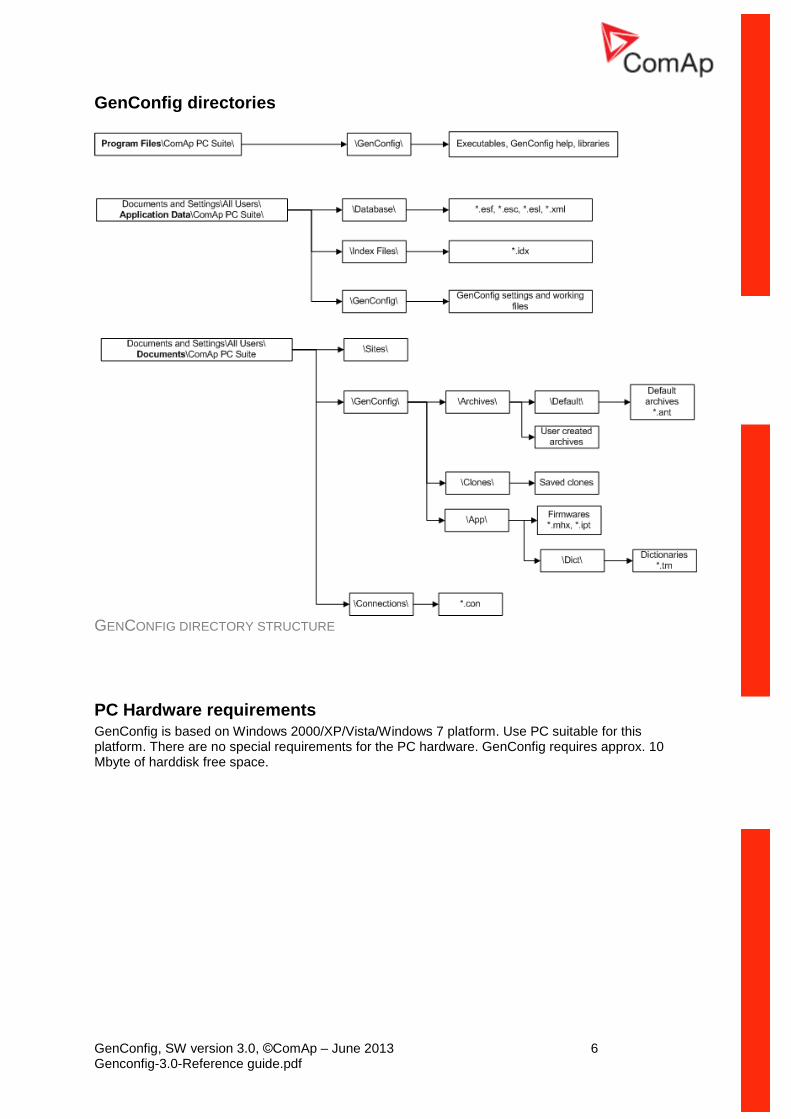
GenConfig directories
GENCONFIG DIRECTORY STRUCTURE
PC Hardware requirements GenConfig is based on Windows 2000/XP/Vista/Windows 7 platform. Use PC suitable for this platform. There are no special requirements for the PC hardware. GenConfig requires approx. 10 Mbyte of harddisk free space.
GenConfig, SW version 3.0, ©ComAp – June 2013 7 Genconfig-3.0-Reference guide.pdf
Basic and advanced modes
There are two program modes available. Basic mode will fit to those people, who do not need special features of the controller and like simpler program interface, less settings etc. The Advanced mode is then for those, who need all functions and features.
Go to Options -> Settings -> Display to select the program mode.
NOTE: Each archive contains information about GenConfig mode last time used for modification of it. If an archive has been modified with GenConfig running in advanced mode, it is no more possible to work with this archive in basic mode, so next time you will open this archive (from the controller or from file) and the GenConfig is set to basic mode, it will switch automatically and temporarily into advanced mode. NOTE: Archives from older firmware versions, which do not support the basic mode, are opened as advanced automatically.
Archive versus Configuration
The table below explains meaning of the terms archive and configuration and difference between them.
Archive
Package of data which is read out from a controller and can be stored in a file. File extension for IGS-NT family archives is "ant". An archive contains following data:
Configuration
Setpoints
Current operational values
History (performance log)
Default archives are distributed together with the controller firmware and contain default configuration and default adjustment of setpoints. These archives do not contain operational values and history.
Configuration
A segment of data (stored in the controller flash memory), which contains properties of attached modules, inputs, outputs, protections, languages, PLC and other information. The configuration can be changed only with GenConfig. Normally the configuration needs to be changed only to adapt the controller to the site requirements prior to or during commisioning. Obviously there is no need to change it during the lifecycle of the gen-set. NOTE: Configuration is contained in each archive!
GenConfig, SW version 3.0, ©ComAp – June 2013 8 Genconfig-3.0-Reference guide.pdf
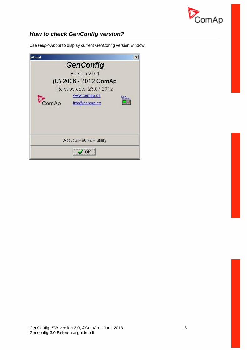
How to check GenConfig version?
Use Help->About to display current GenConfig version window.
GenConfig, SW version 3.0, ©ComAp – June 2013 9 Genconfig-3.0-Reference guide.pdf
Working with GenConfig
In principle GenConfig software should be used as an off-line tool to create or change the configuration and write it to the controller. Communication with the controller is running only while the configuration is being read and written to the controller. During this time you can see the InteliDDE server running.
NOTE: Although GenConfig can be started directly from Windows start menu, it is intended to be started from InteliMonitor:
1. Start InteliMonitor and click on Connection -> Open to activate the Open connection window.
2. Create new site/gen-set in the Open connection window if required or select Quick connect to
controller if you do not want to work with sites.
3. Select desired type of connection and click to Open connection button.
4. Once the connection is running (InteliMonitor status line is green..) start GenConfig by clicking
on Tools -> GenConfig. GenConfig will read the configuration from the controller
automatically.
GenConfig, SW version 3.0, ©ComAp – June 2013 10 Genconfig-3.0-Reference guide.pdf
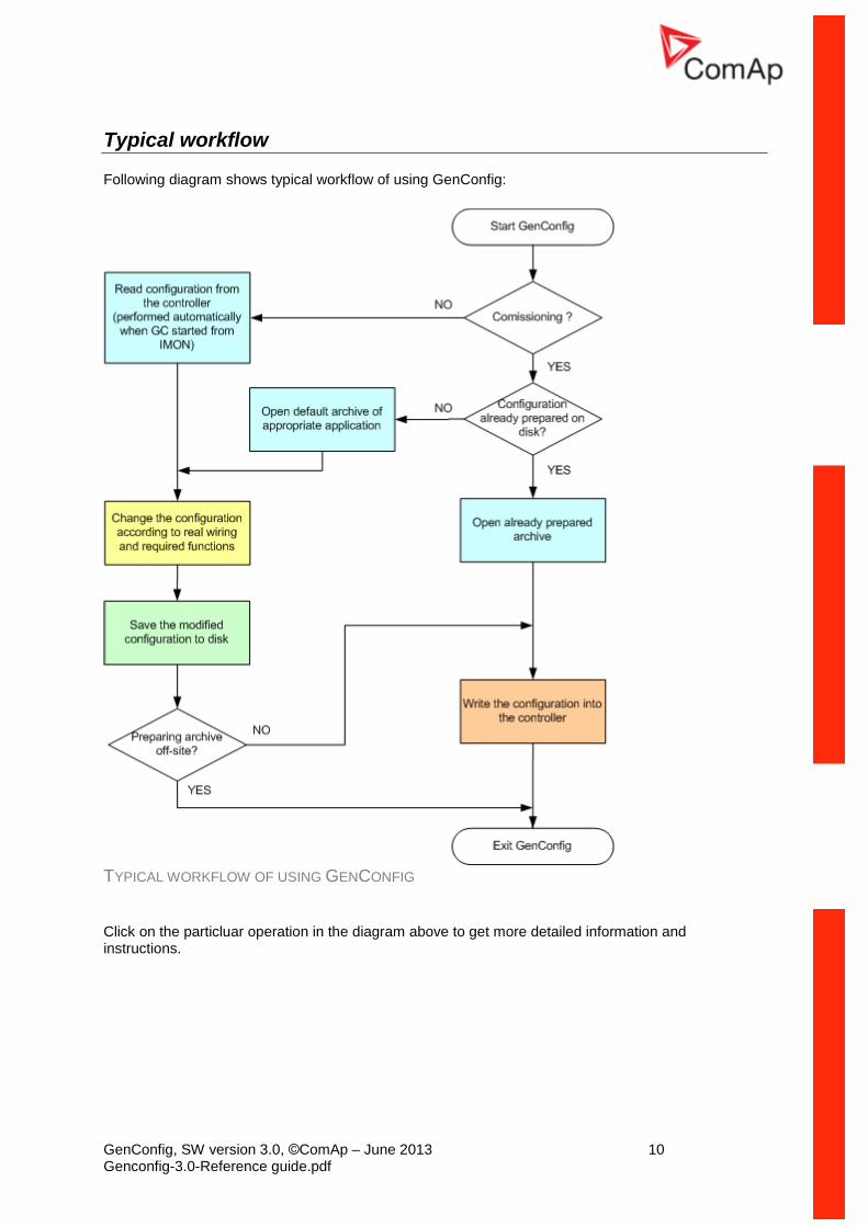
Typical workflow
Following diagram shows typical workflow of using GenConfig:
TYPICAL WORKFLOW OF USING GENCONFIG
Click on the particluar operation in the diagram above to get more detailed information and instructions.
GenConfig, SW version 3.0, ©ComAp – June 2013 11 Genconfig-3.0-Reference guide.pdf
Open archive from disk
Click to icon or select File -> Open to activate a dialog for opening an archive.
The default archives are located in shared documents folder: C:\Documents and Settings\All Users\Documents\ComAp PC Suite\GenConfig\Archives\Default
The user created archives are intended to be in shared documents folder as well: C:\Documents
and Settings\All Users\Documents\ComAp PC Suite\GenConfig\Archives, however
they can be read from anywhere in the computer.
Read archive from controller
Click to icon or use File -> Read from controller to read out the archive from a connected
controller.
CAUTION! Make sure that Connection settings are adjusted properly prior to reading the archive. Wrong connection settings may cause you will read out the archive from different controller than intended. NOTE: If GenConfig is started from InteliMonitor, then the connections settings are adjusted by InteliMonitor and the archive is read out from the controller automatically.
Write configuration to the controller
Click to icon or use File -> Write to controller to write the configuration into the connected
controller. Administrator is prompted to log-in to complete this operation. Following options are related to writing the configuration:
Overwrite setpoints
Clear history
CAUTION! Make sure that Connection settings are adjusted properly prior to writing the configuration. Wrong connection settings may cause you will write the configuration into different controller than intended. This situation might occur especially if an ethernet connection is used. NOTE: If GenConfig is started from InteliMonitor, then the connections settings are adjusted by InteliMonitor and do not require any user attention.
GenConfig, SW version 3.0, ©ComAp – June 2013 12 Genconfig-3.0-Reference guide.pdf
Save archive to disk
Click to icon or use File -> Save to save the archive to disk. If a filename is not assigned to the
archive yet, you will be asked for it, otherwise the archive will be saved under the assigned filename.
Use File -> Save As to save the archive under different filename.
Following options are related to saving the archive:
Save history to archive
Check consistency before save
Configuration import
If you want to use a configuration from an archive, which is not directly compatible with your firmware, the configuration import must be used for importing of the configuration from the original archive into the compatible default archive according to your firmware.
1. Open the target default archive into which you want to import the configuration.
2. Go to menu File -> Import configuration wizard
3. Select the source archive and press Next button.
4. The following window shows differencies between the configurations. You can not make any modifications here.
5. Press Next button to execute the import function.
6. When the import is finished, press Next button to see the information window with the results.
Here you will see possible warnings or errors that occurred during the import.
7. Press OK button to finish the import.
CAUTION! Check the new configuration, especially if some warnings or errors occurred. It may need manual corrections. Manual corrections are required if the configuration was imported from different firmware branch or different application type, as certain functions may not be present in the target firmware.
Archive compatibility overview
Compatible archives:
Archives from different releases of the same firmware and major + minor version (e.g. IG-NT-2.3 x IG-NT-2.3.1 x IG-NT-2.3.2)
Incompatible archives:
Archives from different major or minor versions of the same firmware branch (IG-NT-2.2 x IG-NT-2.3)
Archives from different firmware branches
Archives from different controller types (IG-NT x IS-NT)
GenConfig, SW version 3.0, ©ComAp – June 2013 13 Genconfig-3.0-Reference guide.pdf
Controller firmware upgrade
Although the controllers are supplied always with latest version of standard firmware it may be needed in some cases to upgrade the firmware to newer version. Also customized firmware branches require the controller firmware to be reprogrammed.
NOTE: Administrator is prompted to log-in prior to programming of firmware and/or configuration into the controller.
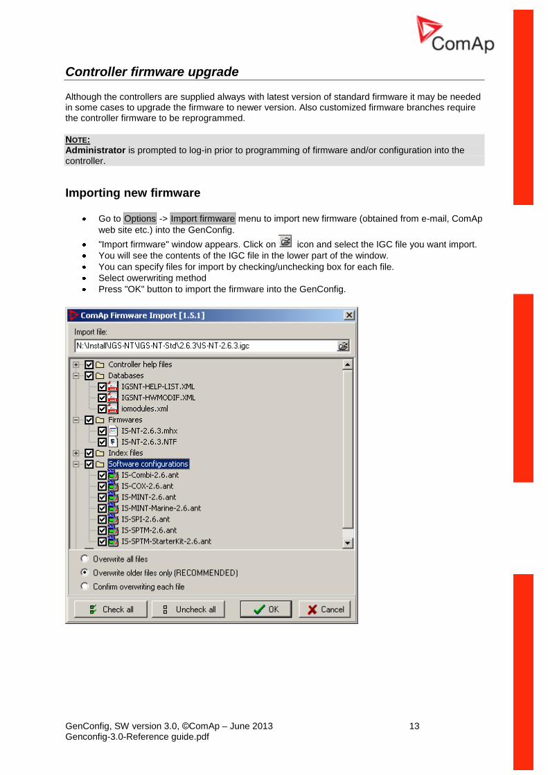
Importing new firmware
Go to Options -> Import firmware menu to import new firmware (obtained from e-mail, ComAp
web site etc.) into the GenConfig.
"Import firmware" window appears. Click on icon and select the IGC file you want import.
You will see the contents of the IGC file in the lower part of the window.
You can specify files for import by checking/unchecking box for each file.
Select owerwriting method
Press "OK" button to import the firmware into the GenConfig.
GenConfig, SW version 3.0, ©ComAp – June 2013 14 Genconfig-3.0-Reference guide.pdf
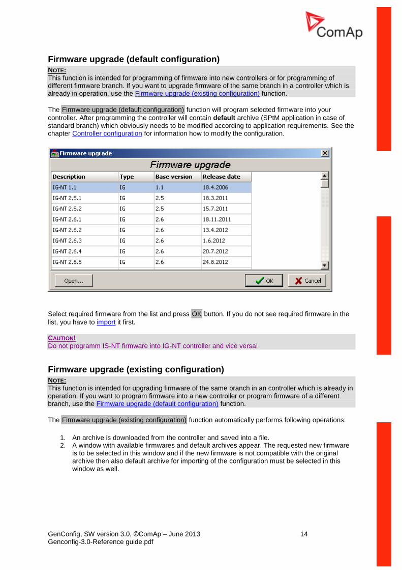
Firmware upgrade (default configuration) NOTE: This function is intended for programming of firmware into new controllers or for programming of different firmware branch. If you want to upgrade firmware of the same branch in a controller which is already in operation, use the Firmware upgrade (existing configuration) function.
The Firmware upgrade (default configuration) function will program selected firmware into your
controller. After programming the controller will contain default archive (SPtM application in case of standard branch) which obviously needs to be modified according to application requirements. See the chapter Controller configuration for information how to modify the configuration.
Select required firmware from the list and press OK button. If you do not see required firmware in the
list, you have to import it first.
CAUTION! Do not programm IS-NT firmware into IG-NT controller and vice versa!
Firmware upgrade (existing configuration) NOTE: This function is intended for upgrading firmware of the same branch in an controller which is already in operation. If you want to program firmware into a new controller or program firmware of a different branch, use the Firmware upgrade (default configuration) function.
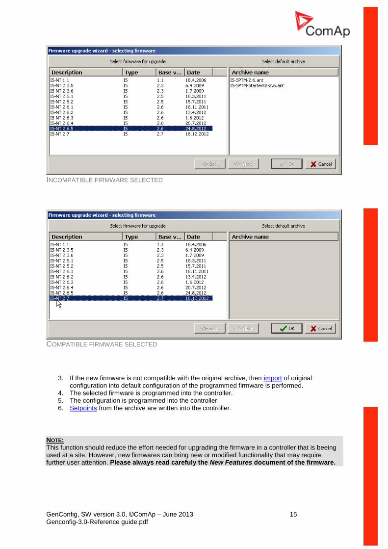
The Firmware upgrade (existing configuration) function automatically performs following operations:
1. An archive is downloaded from the controller and saved into a file. 2. A window with available firmwares and default archives appear. The requested new firmware
is to be selected in this window and if the new firmware is not compatible with the original archive then also default archive for importing of the configuration must be selected in this window as well.
GenConfig, SW version 3.0, ©ComAp – June 2013 15 Genconfig-3.0-Reference guide.pdf
INCOMPATIBLE FIRMWARE SELECTED
COMPATIBLE FIRMWARE SELECTED
3. If the new firmware is not compatible with the original archive, then import of original configuration into default configuration of the programmed firmware is performed.
4. The selected firmware is programmed into the controller. 5. The configuration is programmed into the controller. 6. Setpoints from the archive are written into the controller.
NOTE: This function should reduce the effort needed for upgrading the firmware in a controller that is beeing used at a site. However, new firmwares can bring new or modified functionality that may require further user attention. Please always read carefuly the New Features document of the firmware.
GenConfig, SW version 3.0, ©ComAp – June 2013 16 Genconfig-3.0-Reference guide.pdf
Cloning
Use cloning function to create an identical copy of one controller to another one. This function can help you in following situations:
Replacing defective controller with another controller on one site.
Production of more identical gen-sets.
The procedure consists of following steps:
1. Save for later cloning 2. Create clone
Contents of a clone:
Clone description file
Controller archive
Controller firmware according to the archive
External display firmwares (optional, for terminals connected to the dedicated terminal RS485 line)
Graphic fonts (optional, only for controllers/terminals that support graphic fonts)
Save for later cloning
Save for later clonning (controller only) function will save currently opened configuration including all
changes that were made since opening it from disk or reading from controller. This option does not save firmwares of external terminals and graphic fonts into the clone.
Save for later clonning (controller and displays) function connects automatically to the controller,
reads the configuration from it and saves it into the clone. Firmwares of external terminals connected via the dedicated RS485 bus and graphic fonts are saved into the clone as well.
NOTE: If you get an error message "Firmware XXXX was not found" instead of opening the "Save clone" window, it means you do not have on your disk the firmware, that is present in the controller, so the clone can't be saved. In such a case the proper firmware has to be imported into the GenConfig.
Create clone
Use the function Create clone... to make the connected controller identical (firmware, configuration,
setpoints, fonts..) with the original controller from which was the clone saved. The function is intended to be used either for the purpose of complete backup of a site in case the controller or terminal will need to be replaced or for preparing of more identical controllers.
1. Connect the target controller (and displays if needed) to the PC. 2. Start GenConfig and adjust properly connection settings.
3. Go to menu File -> Create clone... and then select required clone.
4. Press OK to program the selected clone into the controller.
Import/Export clone
Press the to export selected saved clone into one file for the purpose of archivation, sending
per e-mail etc. Press the to import previously saved clone into GenConfig.
GenConfig, SW version 3.0, ©ComAp – June 2013 17 Genconfig-3.0-Reference guide.pdf
Programming firmware into a non-responding controller If the controller does not contain valid firmware a new firmware can't be programmed by standard way. This situation can occur if the connection between PC and the controller was interrupted during previous firmware upgrade. In such a case the controller has blank display and does not communicate with the PC. The boot-jumper must be used to get a valid firmware into the controller.
1. Disconnect power supply from the controller and close the boot-jumper. See the controller manual for details about boot-jumper location.
2. Connect communication cable (appropriate type according to the module used) between the controller and PC.
3. Select direct connection to controller address 1.
4. Go to menu Controller -> Programming and clonning -> Firmware upgrade, select
appropriate firmware and press OK button.
5. Follow instructions given by a message appeared and finally press OK button.
6. Another message will appear when programming is finished. Follow instructions given there.
GenConfig, SW version 3.0, ©ComAp – June 2013 18 Genconfig-3.0-Reference guide.pdf
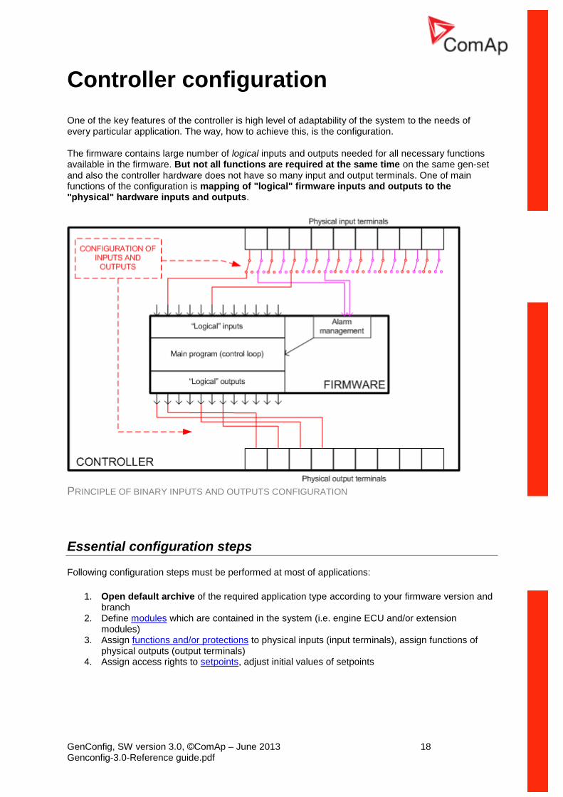
Controller configuration
One of the key features of the controller is high level of adaptability of the system to the needs of every particular application. The way, how to achieve this, is the configuration.
The firmware contains large number of logical inputs and outputs needed for all necessary functions available in the firmware. But not all functions are required at the same time on the same gen-set and also the controller hardware does not have so many input and output terminals. One of main functions of the configuration is mapping of "logical" firmware inputs and outputs to the "physical" hardware inputs and outputs.
PRINCIPLE OF BINARY INPUTS AND OUTPUTS CONFIGURATION
Essential configuration steps
Following configuration steps must be performed at most of applications:
1. Open default archive of the required application type according to your firmware version and branch
2. Define modules which are contained in the system (i.e. engine ECU and/or extension modules)
3. Assign functions and/or protections to physical inputs (input terminals), assign functions of physical outputs (output terminals)
4. Assign access rights to setpoints, adjust initial values of setpoints
GenConfig, SW version 3.0, ©ComAp – June 2013 19 Genconfig-3.0-Reference guide.pdf
Optional configuration steps
Following configuration steps may not be needed to go through at less complex applications:
1. Assign access rights to remote gen-set control commands 2. Create additional protections to any analog value 3. Modify content of the history header 4. Create user-defined analog sensor conversion characteristics 5. Add/Remove controller languages, translate the texts 6. Create internal connections from logical outputs to logical inputs 7. Create PLC program for control of additional technology
NOTE: There are two modes of GenConfig operation - Basic mode and Advanced mode. Some features are hidden in the basic mode. Learn more in the chapter Basic and advanced modes.
Configuration locking
It is possible to lock the archive against unauthorized usage. If the archive is locked, the user 0 password (administarator password) is required to open and display the archive in GenConfig.
NOTE: The configuration lock works only if the configuration has been downloaded from the controller and requires password that was vaild in the moment of downloading. The configuration lock is not active in configurations derived directly from default archives that were not uploaded into the controller yet.
GenConfig, SW version 3.0, ©ComAp – June 2013 20 Genconfig-3.0-Reference guide.pdf
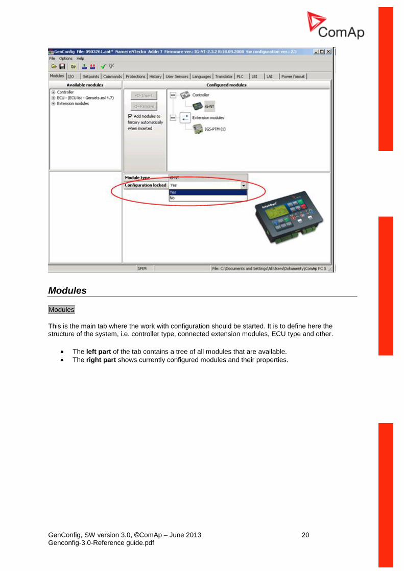
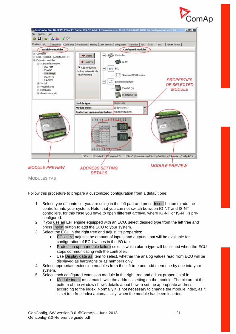
Modules
Modules
This is the main tab where the work with configuration should be started. It is to define here the structure of the system, i.e. controller type, connected extension modules, ECU type and other.
The left part of the tab contains a tree of all modules that are available.
The right part shows currently configured modules and their properties.
GenConfig, SW version 3.0, ©ComAp – June 2013 21 Genconfig-3.0-Reference guide.pdf
MODULES TAB
Follow this procedure to prepare a customized configuration from a default one:
1. Select type of controller you are using in the left part and press Insert button to add the
controller into your system. Note, that you can not switch between IG-NT and IS-NT controllers, for this case you have to open different archive, where IG-NT or IS-NT is pre-configured.
2. If you use an EFI engine equipped with an ECU, select desired type from the left tree and
press Insert button to add the ECU to your system.
3. Select the ECU in the right tree and adjust it's properties:
ECU size adjusts the amount of inputs and outputs, that will be available for
configuration of ECU values in the I/O tab.
Protection upon module failure selects which alarm type will be issued when the ECU
stops communicating with the controller.
Use Display data as item to select, whether the analog values read from ECU will be
displayed as bargraphs or as numbers only. 4. Select appropriate extension modules from the left tree and add them one by one into your
system. 5. Select each configured extension module in the right tree and adjust properties of it:
Module index must match with the address setting on the module. The picture at the
bottom of the window shows details about how to set the appropriate address according to the index. Normally it is not necessary to change the module index, as it is set to a free index automatically, when the module has been inserted.
GenConfig, SW version 3.0, ©ComAp – June 2013 22 Genconfig-3.0-Reference guide.pdf
NOTE:
Some modules share physical CAN addresses and this can cause using one type of module with specific index will disable using another module with specific index. Example: if AIN8 modules with indexes 1 - 4 are configured, it will be not possible to configure IGS-PTM module, as the IGS-PTM index 1 – 4 shares the CAN addresses with AIN8 modules. In such a case the solution is to configure AIN8 modules to indexes 2-5 and the IGS-PTM to the index 1.
Protection upon module failure selects which alarm type will be issued when the
module stops communicating with the controller.
Use Display data as item to select, whether the analog values read from the module
will be displayed as bargraphs or as numbers only.
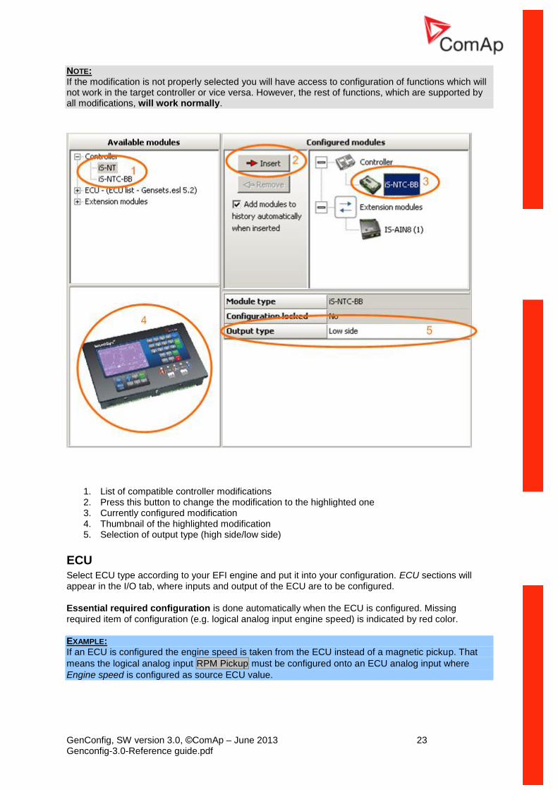
Controller
Below version 2.5 of standard firmware
The controller type is fixedly configured in the archive and it can not be changed. There are different firmware files and default archives for IG-NT and for IS-NT controllers.
Changing of the controller type is possible only from IG-NT to IG-EE and vice versa.
Version 2.5 of standard firmware and above
There are groups of compatible hardware modifications of the controller and separate firmware and archive for each group, which works with each controller modification from the particular group. The groups are following:
COMPATIBLE CONTROLLER MODIFICATIONS FIRMWARE FILE ARCHIVE FILE
IG-NT, IG-NTC, IG-EE(C), IG-NT-BB, IG-NTC-BB ig-nt-x.y.z.mhx ig-appl-x.y.ant
IS-NT, IS-NTC-BB is-nt-x.y.z.mhx is-appl-x.y.ant
IM-NT, IM-NT-BB, IM-NTC-BB im-nt-x.y.z.mhx im-appl-x.y.ant
It is possible to change the controller modification to any of the compatible modifications. GenConfig will then show and hide certain adjustments and configuration items according to what does the selected modification support and what doesn't.
NOTE: Default archives for the each group are configured to IG-NT, IS-NT or IM-NT respectively. However, to get access to all features and functions that are supported by your controller you have to change the controller modification in the configuration to match the target controller. EXAMPLE: The default IG-NT-MINT archive is switched to IG-NT modification, which does not support high side switches at the outputs. If you have IG-NT-BB hardware, which supports HSS, you have to change the modification to IG-NT-BB and then you will be able to select the HSS mode for controller outputs.
GenConfig, SW version 3.0, ©ComAp – June 2013 23 Genconfig-3.0-Reference guide.pdf
NOTE: If the modification is not properly selected you will have access to configuration of functions which will not work in the target controller or vice versa. However, the rest of functions, which are supported by all modifications, will work normally.
1. List of compatible controller modifications 2. Press this button to change the modification to the highlighted one 3. Currently configured modification 4. Thumbnail of the highlighted modification 5. Selection of output type (high side/low side)
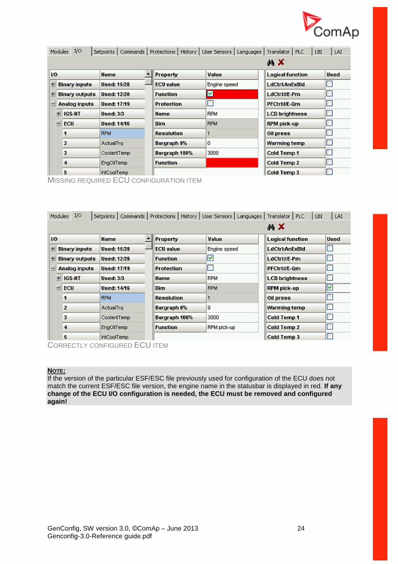
ECU Select ECU type according to your EFI engine and put it into your configuration. ECU sections will appear in the I/O tab, where inputs and output of the ECU are to be configured.
Essential required configuration is done automatically when the ECU is configured. Missing required item of configuration (e.g. logical analog input engine speed) is indicated by red color.
EXAMPLE: If an ECU is configured the engine speed is taken from the ECU instead of a magnetic pickup. That
means the logical analog input RPM Pickup must be configured onto an ECU analog input where
Engine speed is configured as source ECU value.
GenConfig, SW version 3.0, ©ComAp – June 2013 24 Genconfig-3.0-Reference guide.pdf
MISSING REQUIRED ECU CONFIGURATION ITEM
CORRECTLY CONFIGURED ECU ITEM
NOTE: If the version of the particular ESF/ESC file previously used for configuration of the ECU does not match the current ESF/ESC file version, the engine name in the statusbar is displayed in red. If any change of the ECU I/O configuration is needed, the ECU must be removed and configured again!
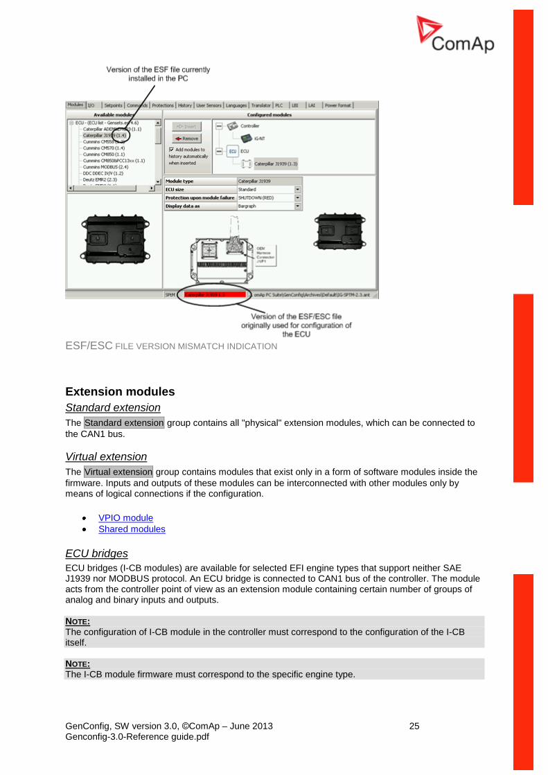
GenConfig, SW version 3.0, ©ComAp – June 2013 25 Genconfig-3.0-Reference guide.pdf
ESF/ESC FILE VERSION MISMATCH INDICATION
Extension modules
Standard extension
The Standard extension group contains all "physical" extension modules, which can be connected to
the CAN1 bus.
Virtual extension
The Virtual extension group contains modules that exist only in a form of software modules inside the
firmware. Inputs and outputs of these modules can be interconnected with other modules only by means of logical connections if the configuration.
VPIO module
Shared modules
ECU bridges
ECU bridges (I-CB modules) are available for selected EFI engine types that support neither SAE J1939 nor MODBUS protocol. An ECU bridge is connected to CAN1 bus of the controller. The module acts from the controller point of view as an extension module containing certain number of groups of analog and binary inputs and outputs.
NOTE: The configuration of I-CB module in the controller must correspond to the configuration of the I-CB itself. NOTE: The I-CB module firmware must correspond to the specific engine type.
GenConfig, SW version 3.0, ©ComAp – June 2013 26 Genconfig-3.0-Reference guide.pdf
How to configure an I-CB module:
1. Check whether the I-CB module contains appropriate firmware according to your engine (ECU) type. The original firmware type and version is indicated on the sticker at the I-CB module.
2. In ICBEdit open the default I-CB configuration according to your engine type, modify it if needed, and write it into the I-CB.
3. Use ICBEdit menu File -> Export... to export the I-CB configuration into a text file.
4. In GenConfig put an I-CB of appropriate type into your configuration and then go to the I/O
Tab and configure inputs and outputs.
NOTE: Always use electronic sensor type for analog inputs at ECU bridges.
Generic extension
There is also the I-CB (generic) available, which is not prepared for any specific engine and by default
does not contain any inputs and outputs. Groups of inputs and outputs must be configured then
manually using the generic modules from the Generic extension group.
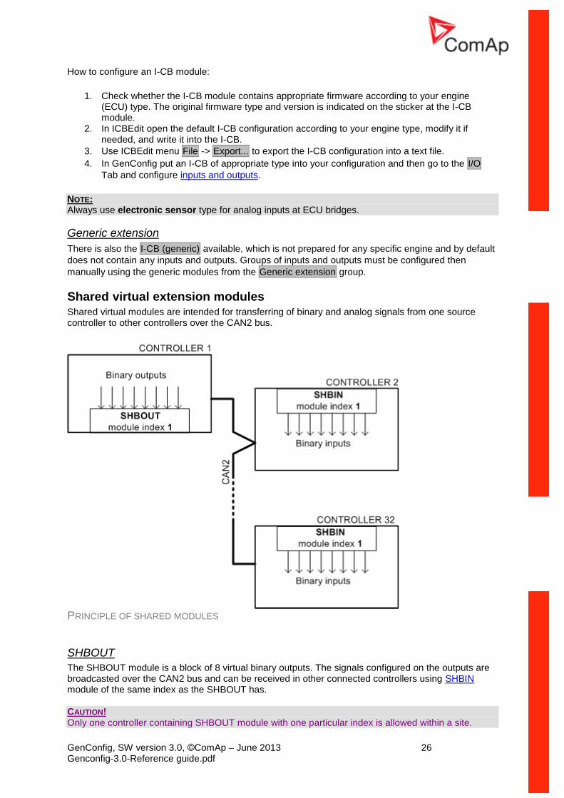
Shared virtual extension modules Shared virtual modules are intended for transferring of binary and analog signals from one source controller to other controllers over the CAN2 bus.
PRINCIPLE OF SHARED MODULES
SHBOUT
The SHBOUT module is a block of 8 virtual binary outputs. The signals configured on the outputs are broadcasted over the CAN2 bus and can be received in other connected controllers using SHBIN module of the same index as the SHBOUT has.
CAUTION! Only one controller containing SHBOUT module with one particular index is allowed within a site.
GenConfig, SW version 3.0, ©ComAp – June 2013 27 Genconfig-3.0-Reference guide.pdf
SHBIN
The SHBIN module is a block of 8 virtual binary inputs intended for receiving of binary signals that are broadcasted by SHBOUT module.
NOTE: The receiving SHBIN module must have identical module index as the broadcasting one.
SHAOUT
The SHAIN module is a block of 4 virtual analog outputs. The signals configured on the outputs are broadcasted over the CAN2 bus and can be received in other connected controllers using SHAIN module of the same index as the SHAOUT has.
CAUTION! Only one controller containing SHAOUT module with one particular index is allowed within a site.
SHAIN
The SHAIN module is a block of 4 virtual analog inputs intended for receiving of analog signals that are broadcasted by SHAOUT module.
NOTE: The receiving SHAIN module must have identical module index as the broadcasting one. NOTE: Always use electronic sensor type for analog inputs of the SHAIN modules.
DISTBOUT
The DISTBOUT module is a block of 8 virtual binary outputs. The signals configured on the outputs are broadcasted over the CAN2 bus and can be received in other connected controllers using DISTBIN module of the same index as the DISTBOUT has. DISTBOUT has always module index equal to CAN address of controller.
NOTE: Only one DISTBOUT module per controller can be configured. NOTE: DISTBOUT module is available only in following controllers:
1. IG-NT(C)-BB controllers with firmware 3.0 and higher and LSM-PMS dongle installed. Module is not available in IG-NT GC controller.
2. IS-NT controllers with firmware 3.0 and higher and LSM-PMS dongle installed. 3. IM-NT controllers with firmware 3.0 and higher (no dongle required)
DISTBIN
The DISTBIN module is a block of 8 virtual binary inputs intended for receiving of binary signals that are broadcasted by DISTBOUT module.
NOTE: The receiving DISTBIN module must have identical module index as the broadcasting one. NOTE: Up to 32 DISTBIN modules with unique index (1-32) can be configured per controller.
GenConfig, SW version 3.0, ©ComAp – June 2013 28 Genconfig-3.0-Reference guide.pdf
NOTE: DISTBIN module is available only in following controllers:
1. IG-NT(C)-BB controllers with firmware 3.0 and higher and LSM-PMS dongle installed. Module is not available in IG-NT GC controller.
2. IS-NT controllers with firmware 3.0 and higher and LSM-PMS dongle installed. 3. IM-NT controllers with firmware 3.0 and higher (no dongle required)
GenConfig, SW version 3.0, ©ComAp – June 2013 29 Genconfig-3.0-Reference guide.pdf
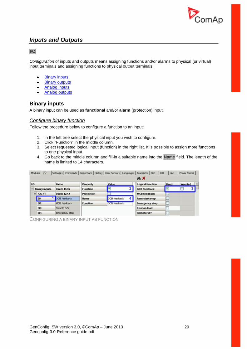
Inputs and Outputs
I/O
Configuration of inputs and outputs means assigning functions and/or alarms to physical (or virtual) input terminals and assigning functions to physical output terminals.
Binary inputs
Binary outputs
Analog inputs
Analog outputs
Binary inputs A binary input can be used as functional and/or alarm (protection) input.
Configure binary function
Follow the procedure below to configure a function to an input:
1. In the left tree select the physical input you wish to configure. 2. Click "Function" in the middle column. 3. Select requested logical input (function) in the right list. It is possible to assign more functions
to one physical input.
4. Go back to the middle column and fill-in a suitable name into the Name field. The length of the
name is limited to 14 characters.
CONFIGURING A BINARY INPUT AS FUNCTION
GenConfig, SW version 3.0, ©ComAp – June 2013 30 Genconfig-3.0-Reference guide.pdf
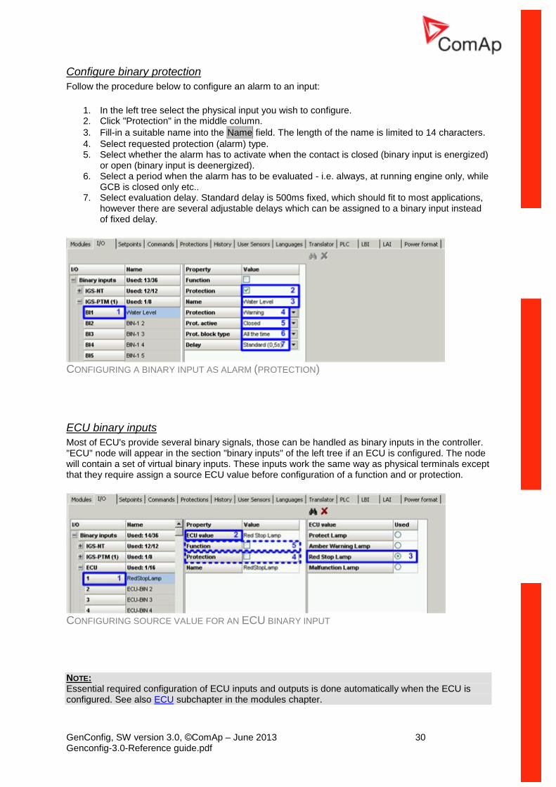
Configure binary protection
Follow the procedure below to configure an alarm to an input:
1. In the left tree select the physical input you wish to configure. 2. Click "Protection" in the middle column.
3. Fill-in a suitable name into the Name field. The length of the name is limited to 14 characters.
4. Select requested protection (alarm) type. 5. Select whether the alarm has to activate when the contact is closed (binary input is energized)
or open (binary input is deenergized). 6. Select a period when the alarm has to be evaluated - i.e. always, at running engine only, while
GCB is closed only etc.. 7. Select evaluation delay. Standard delay is 500ms fixed, which should fit to most applications,
however there are several adjustable delays which can be assigned to a binary input instead of fixed delay.
CONFIGURING A BINARY INPUT AS ALARM (PROTECTION)
ECU binary inputs
Most of ECU's provide several binary signals, those can be handled as binary inputs in the controller. "ECU" node will appear in the section "binary inputs" of the left tree if an ECU is configured. The node will contain a set of virtual binary inputs. These inputs work the same way as physical terminals except that they require assign a source ECU value before configuration of a function and or protection.
CONFIGURING SOURCE VALUE FOR AN ECU BINARY INPUT
NOTE: Essential required configuration of ECU inputs and outputs is done automatically when the ECU is configured. See also ECU subchapter in the modules chapter.
GenConfig, SW version 3.0, ©ComAp – June 2013 31 Genconfig-3.0-Reference guide.pdf
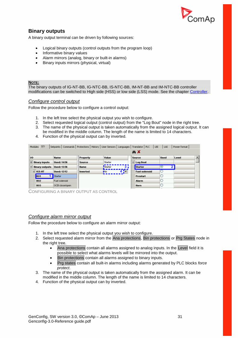
Binary outputs
A binary output terminal can be driven by following sources:
Logical binary outputs (control outputs from the program loop)
Informative binary values
Alarm mirrors (analog, binary or built-in alarms)
Binary inputs mirrors (physical, virtual)
NOTE: The binary outputs of IG-NT-BB, IG-NTC-BB, IS-NTC-BB, IM-NT-BB and IM-NTC-BB controller modifications can be switched to High side (HSS) or low side (LSS) mode. See the chapter Controller.
Configure control output
Follow the procedure below to configure a control output:
1. In the left tree select the physical output you wish to configure. 2. Select requested logical output (control output) from the "Log Bout" node in the right tree. 3. The name of the physical output is taken automatically from the assigned logical output. It can
be modified in the middle column. The length of the name is limited to 14 characters. 4. Function of the physical output can by inverted.
CONFIGURING A BINARY OUTPUT AS CONTROL
Configure alarm mirror output
Follow the procedure below to configure an alarm mirror output:
1. In the left tree select the physical output you wish to configure.
2. Select requested alarm mirror from the Ana protections, Bin protections or Prg States node in
the right tree.
Ana protections contain all alarms assigned to analog inputs. In the Level field it is
possible to select what alarms levels will be mirrored into the output.
Bin protections contain all alarms assigned to binary inputs.
Prg states contain all built-in alarms including alarms generated by PLC blocks force
protect. 3. The name of the physical output is taken automatically from the assigned alarm. It can be
modified in the middle column. The length of the name is limited to 14 characters. 4. Function of the physical output can by inverted.
GenConfig, SW version 3.0, ©ComAp – June 2013 32 Genconfig-3.0-Reference guide.pdf
CONFIGURING A BINARY OUTPUT AS ALARM MIRROR
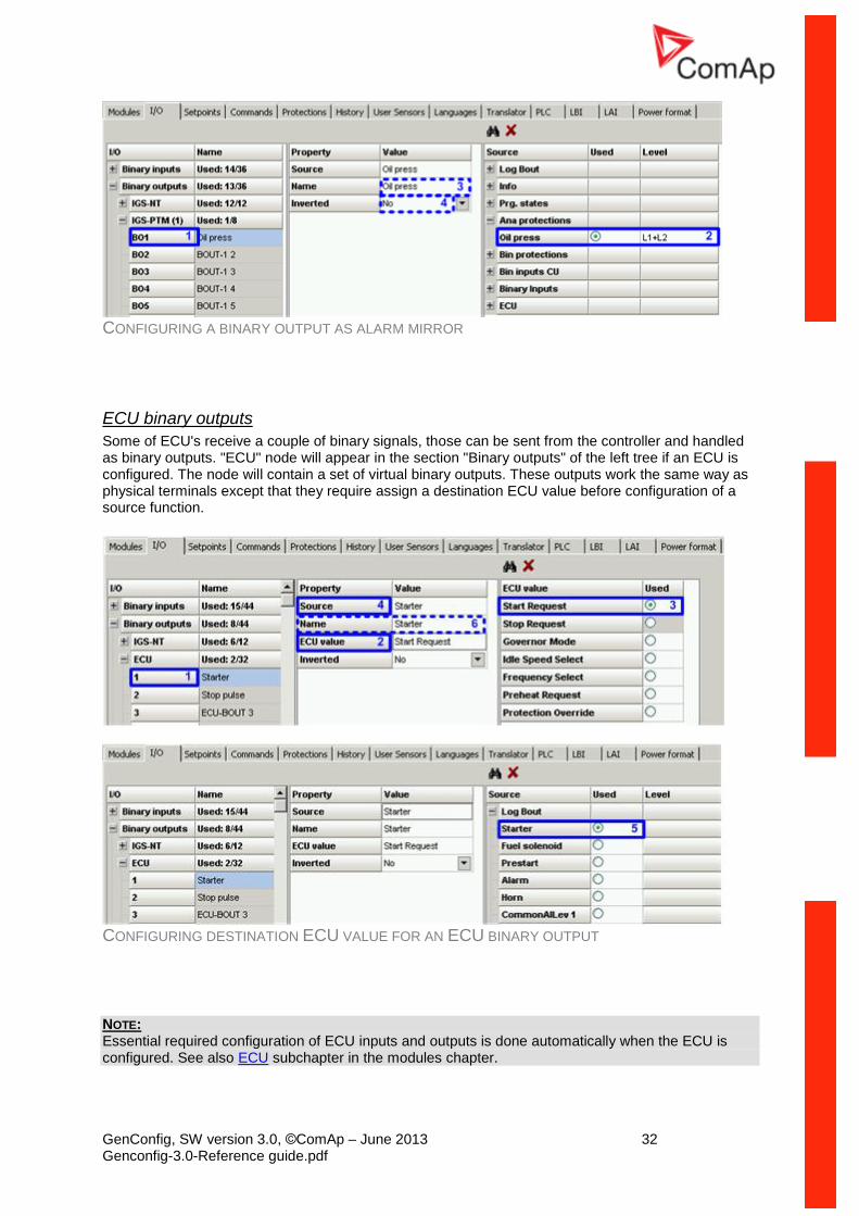
ECU binary outputs
Some of ECU's receive a couple of binary signals, those can be sent from the controller and handled as binary outputs. "ECU" node will appear in the section "Binary outputs" of the left tree if an ECU is configured. The node will contain a set of virtual binary outputs. These outputs work the same way as physical terminals except that they require assign a destination ECU value before configuration of a source function.
CONFIGURING DESTINATION ECU VALUE FOR AN ECU BINARY OUTPUT
NOTE: Essential required configuration of ECU inputs and outputs is done automatically when the ECU is configured. See also ECU subchapter in the modules chapter.
GenConfig, SW version 3.0, ©ComAp – June 2013 33 Genconfig-3.0-Reference guide.pdf
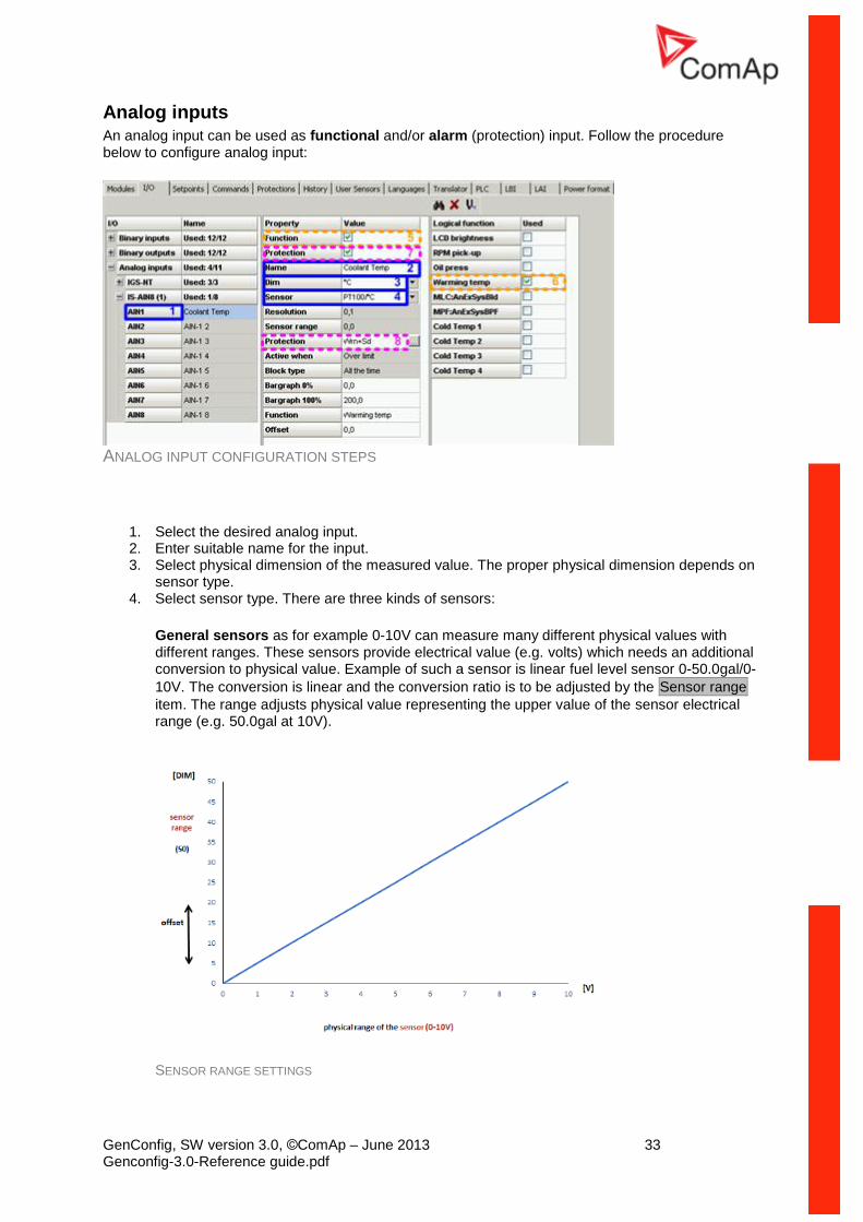
Analog inputs An analog input can be used as functional and/or alarm (protection) input. Follow the procedure below to configure analog input:
ANALOG INPUT CONFIGURATION STEPS
1. Select the desired analog input. 2. Enter suitable name for the input. 3. Select physical dimension of the measured value. The proper physical dimension depends on
sensor type. 4. Select sensor type. There are three kinds of sensors:
General sensors as for example 0-10V can measure many different physical values with different ranges. These sensors provide electrical value (e.g. volts) which needs an additional conversion to physical value. Example of such a sensor is linear fuel level sensor 0-50.0gal/0-
10V. The conversion is linear and the conversion ratio is to be adjusted by the Sensor range
item. The range adjusts physical value representing the upper value of the sensor electrical range (e.g. 50.0gal at 10V).
SENSOR RANGE SETTINGS
GenConfig, SW version 3.0, ©ComAp – June 2013 34 Genconfig-3.0-Reference guide.pdf
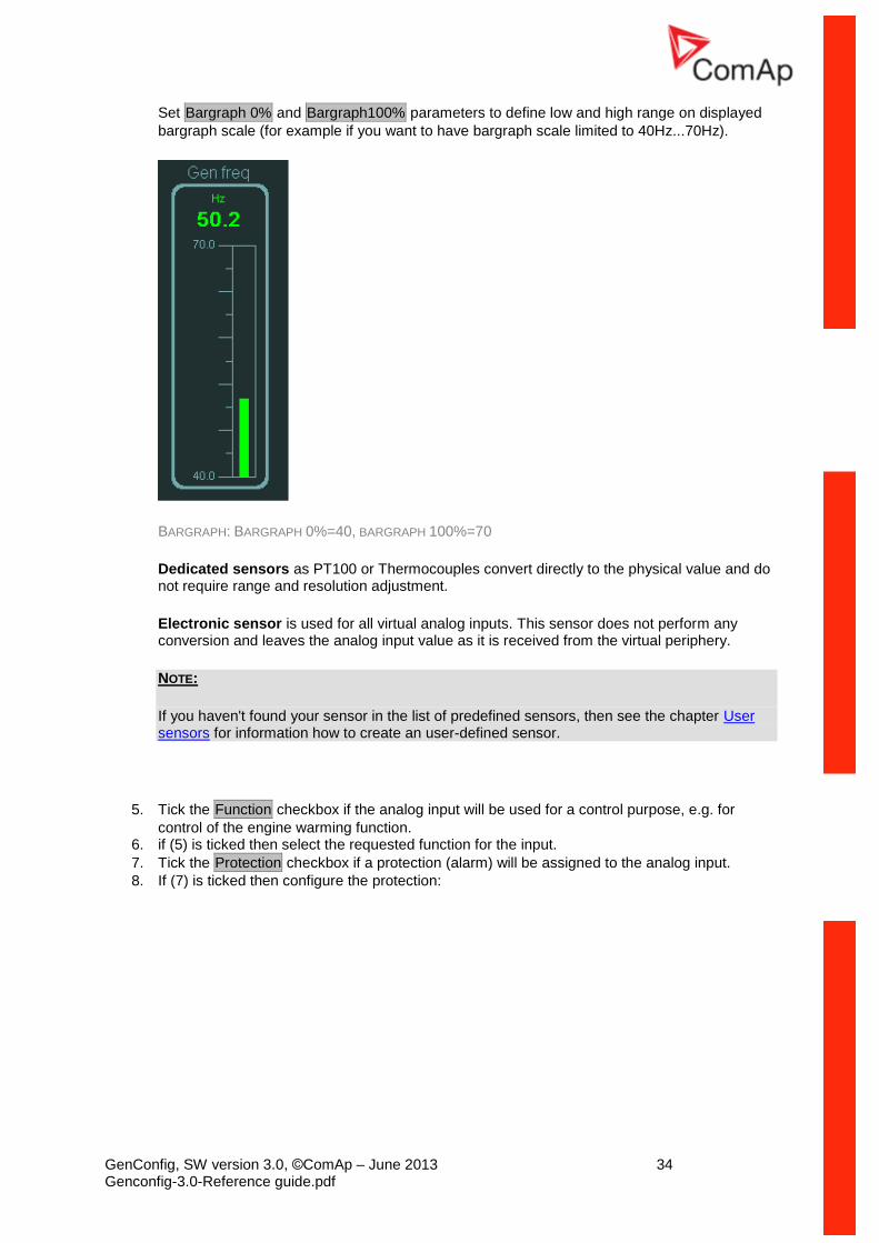
Set Bargraph 0% and Bargraph100% parameters to define low and high range on displayed
bargraph scale (for example if you want to have bargraph scale limited to 40Hz...70Hz).
BARGRAPH: BARGRAPH 0%=40, BARGRAPH 100%=70
Dedicated sensors as PT100 or Thermocouples convert directly to the physical value and do not require range and resolution adjustment.
Electronic sensor is used for all virtual analog inputs. This sensor does not perform any conversion and leaves the analog input value as it is received from the virtual periphery.
NOTE:
If you haven't found your sensor in the list of predefined sensors, then see the chapter User sensors for information how to create an user-defined sensor.
5. Tick the Function checkbox if the analog input will be used for a control purpose, e.g. for
control of the engine warming function. 6. if (5) is ticked then select the requested function for the input.
7. Tick the Protection checkbox if a protection (alarm) will be assigned to the analog input.
8. If (7) is ticked then configure the protection:
GenConfig, SW version 3.0, ©ComAp – June 2013 35 Genconfig-3.0-Reference guide.pdf
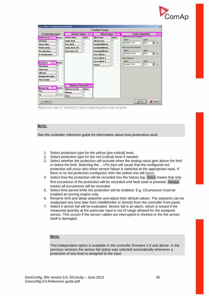
ANALOG INPUT PROTECTION CONFIGURATION STEPS
NOTE:
See the controller reference guide for information about how protections work.
1. Select protection type for the yellow (pre-critical) level. 2. Select protection type for the red (critical) level if needed. 3. Select whether the protection will activate when the analog value gets above the limit
or below the limit. Selecting the ...+Fls item will cause that the configured red protection will occur also when sensor failure is detected at the appropriate input. If there is no red protection configured, then the yellow one will occur.
4. Select how the protection will be recorded into the history log. Once means that only
first occurence of the protection will be recorded until fault reset is pressed, Always
means all occurences will be recorded. 5. Select time period while the protection will be enabled. E.g. Oil pressure must be
enabled at running engine only. 6. Rename limit and delay setpoints and adjust their default values. The setpoints can be
readjusted any time later from InteliMonitor or directly from the controller front panel. 7. Select if sensor fail will be evaluated. Sensor fail is an alarm, which is issued if the
measured quantity at the particular input is out of range allowed for the assigned sensor. This occurs if the sensor cables are interrupted or shorted or the the sensor itself is damaged.
NOTE:
This independent option is available in the controller firmware 2.5 and above. In the previous versions the sensor fail option was selected automatically whenever a protection of any level is assigned to the input
GenConfig, SW version 3.0, ©ComAp – June 2013 36 Genconfig-3.0-Reference guide.pdf
NOTE:
The feature is intended for ECU analog inputs.
CAUTION!
It is not reccomended to configure classic analog input with a protection and without sensor fail option.
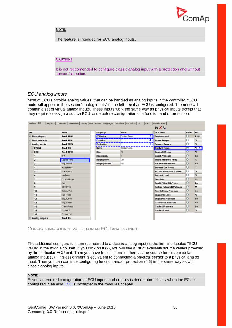
ECU analog inputs
Most of ECU's provide analog values, that can be handled as analog inputs in the controller. "ECU" node will appear in the section "analog inputs" of the left tree if an ECU is configured. The node will contain a set of virtual analog inputs. These inputs work the same way as physical inputs except that they require to assign a source ECU value before configuration of a function and or protection.
CONFIGURING SOURCE VALUE FOR AN ECU ANALOG INPUT
The additional configuration item (compared to a classic analog input) is the first line labeled "ECU value" in the middle column. If you click on it (2), you will see a list of available source values provided by the particular ECU unit. Then you have to select one of them as the source for this particular analog input (3). This assignment is equivalent to connecting a physical sensor to a physical analog input. Then you can continue configuring function and/or protection (4,5) in the same way as with classic analog inputs.
NOTE: Essential required configuration of ECU inputs and outputs is done automatically when the ECU is configured. See also ECU subchapter in the modules chapter.
GenConfig, SW version 3.0, ©ComAp – June 2013 37 Genconfig-3.0-Reference guide.pdf
Cyliders configuration wizard
The wizard makes the configuration of cylinder temperature inputs easier. It helps to configure measurement and 2-level protection with common setpoints for up to 32 cylinder temperature sensors.
Go to the I/O tab, then select the analog input where the first cylinder is connected and press the
button to start the wizard.
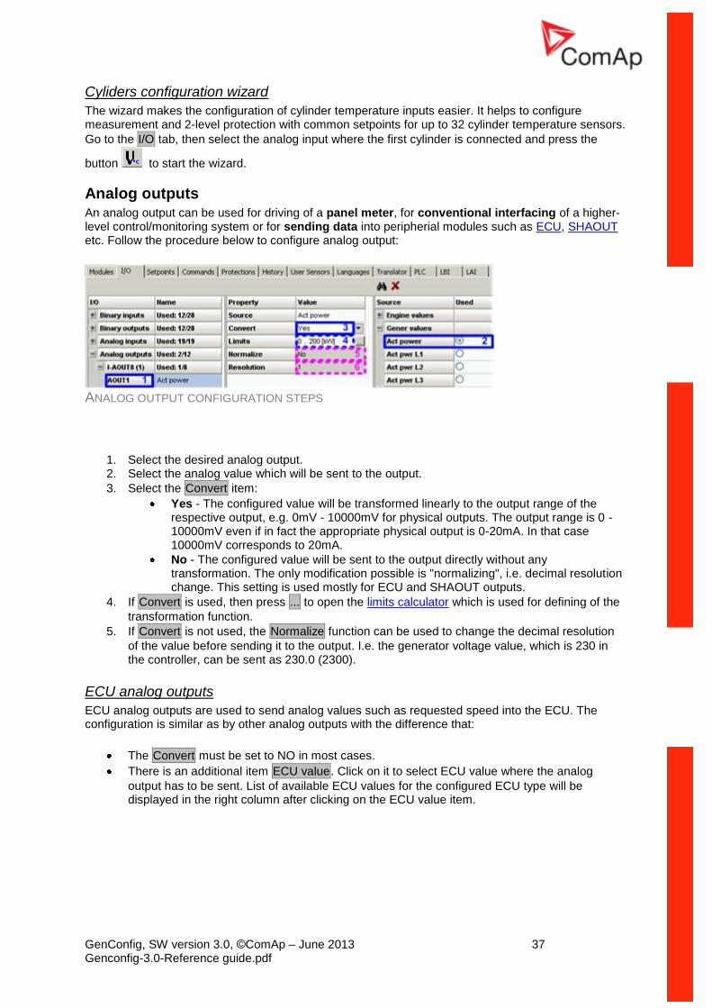
Analog outputs An analog output can be used for driving of a panel meter, for conventional interfacing of a higher-level control/monitoring system or for sending data into peripherial modules such as ECU, SHAOUT etc. Follow the procedure below to configure analog output:
ANALOG OUTPUT CONFIGURATION STEPS
1. Select the desired analog output. 2. Select the analog value which will be sent to the output.
3. Select the Convert item:
Yes - The configured value will be transformed linearly to the output range of the respective output, e.g. 0mV - 10000mV for physical outputs. The output range is 0 - 10000mV even if in fact the appropriate physical output is 0-20mA. In that case 10000mV corresponds to 20mA.
No - The configured value will be sent to the output directly without any transformation. The only modification possible is "normalizing", i.e. decimal resolution change. This setting is used mostly for ECU and SHAOUT outputs.
4. If Convert is used, then press ... to open the limits calculator which is used for defining of the
transformation function.
5. If Convert is not used, the Normalize function can be used to change the decimal resolution
of the value before sending it to the output. I.e. the generator voltage value, which is 230 in the controller, can be sent as 230.0 (2300).
ECU analog outputs
ECU analog outputs are used to send analog values such as requested speed into the ECU. The configuration is similar as by other analog outputs with the difference that:
The Convert must be set to NO in most cases.
There is an additional item ECU value. Click on it to select ECU value where the analog
output has to be sent. List of available ECU values for the configured ECU type will be displayed in the right column after clicking on the ECU value item.
GenConfig, SW version 3.0, ©ComAp – June 2013 38 Genconfig-3.0-Reference guide.pdf
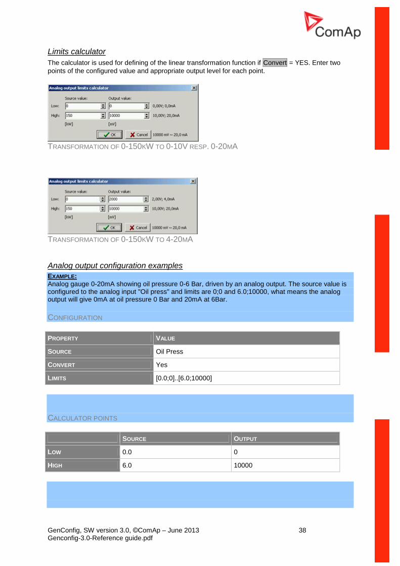
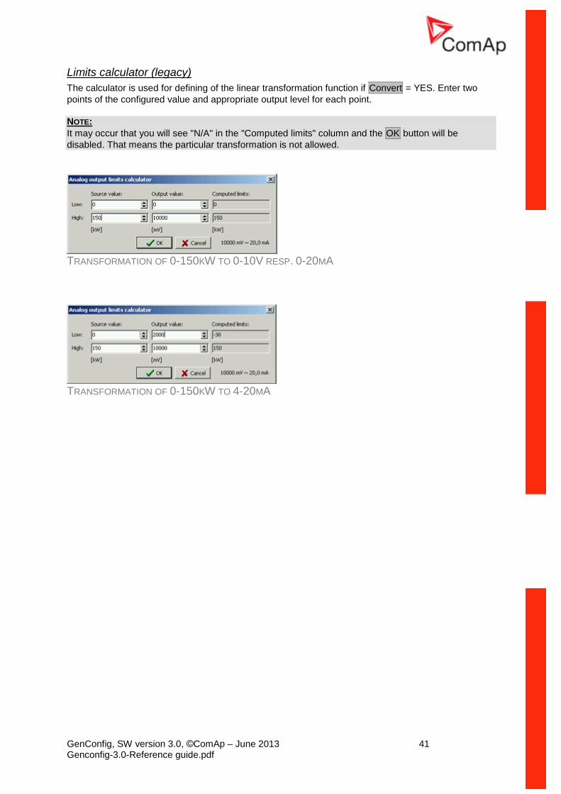
Limits calculator
The calculator is used for defining of the linear transformation function if Convert = YES. Enter two
points of the configured value and appropriate output level for each point.
TRANSFORMATION OF 0-150KW TO 0-10V RESP. 0-20MA
TRANSFORMATION OF 0-150KW TO 4-20MA
Analog output configuration examples
EXAMPLE: Analog gauge 0-20mA showing oil pressure 0-6 Bar, driven by an analog output. The source value is configured to the analog input "Oil press" and limits are 0;0 and 6.0;10000, what means the analog output will give 0mA at oil pressure 0 Bar and 20mA at 6Bar.
CONFIGURATION
PROPERTY VALUE
SOURCE Oil Press
CONVERT Yes
LIMITS [0.0;0]..[6.0;10000]
CALCULATOR POINTS
SOURCE OUTPUT
LOW 0.0 0
HIGH 6.0 10000
GenConfig, SW version 3.0, ©ComAp – June 2013 39 Genconfig-3.0-Reference guide.pdf
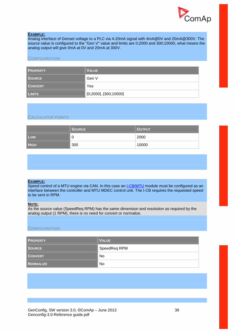
EXAMPLE: Analog interface of Genset voltage to a PLC via 4-20mA signal with 4mA@0V and 20mA@300V. The source value is configured to the "Gen V" value and limits are 0;2000 and 300;10000, what means the analog output will give 0mA at 0V and 20mA at 300V.
CONFIGURATION
PROPERTY VALUE
SOURCE Gen V
CONVERT Yes
LIMITS [0;2000]..[300;10000]
CALCULATOR POINTS
SOURCE OUTPUT
LOW 0 2000
HIGH 300 10000
EXAMPLE: Speed control of a MTU engine via CAN. In this case an I-CB/MTU module must be configured as an interface between the controller and MTU MDEC control unit. The I-CB requires the requested speed to be sent in RPM.
NOTE: As the source value (SpeedReq RPM) has the same dimension and resolution as required by the analog output (1 RPM), there is no need for convert or normalize.
CONFIGURATION
PROPERTY VALUE
SOURCE SpeedReq RPM
CONVERT No
NORMALIZE No
GenConfig, SW version 3.0, ©ComAp – June 2013 40 Genconfig-3.0-Reference guide.pdf
EXAMPLE: Speed control of a Volvo AUX engine via CAN J1939 (using APP value of VP_AUX propietary frame). The APP value of the VP_AUX frame has range of 0-100.0%.
NOTE: As the source value (Speed request) has the same dimension and resolution as required by the VP_AUX frame (0.1%), there is no need for convert or normalize.
CONFIGURATION
PROPERTY VALUE
SOURCE Speed request
CONVERT No
ECU VALUE Accelerator Pedal Position
NORMALIZE No
EXAMPLE: Speed control of a John Deere engine via CAN J1939 (using TSC1 frame). The TSC1 frame requires the requested speed in RPM.
NOTE: As the source value (SpeedReq RPM) has the same dimension and resolution as required by the TSC1 frame (1 RPM), there is no need for convert or normalize.
CONFIGURATION
PROPERTY VALUE
SOURCE SpeedReq RPM
CONVERT No
ECU VALUE Requested speed
NORMALIZE No
NOTE: See the ComAp Electronic Engines Support guide for detailed information about speed control of electronic engines.
GenConfig, SW version 3.0, ©ComAp – June 2013 41 Genconfig-3.0-Reference guide.pdf
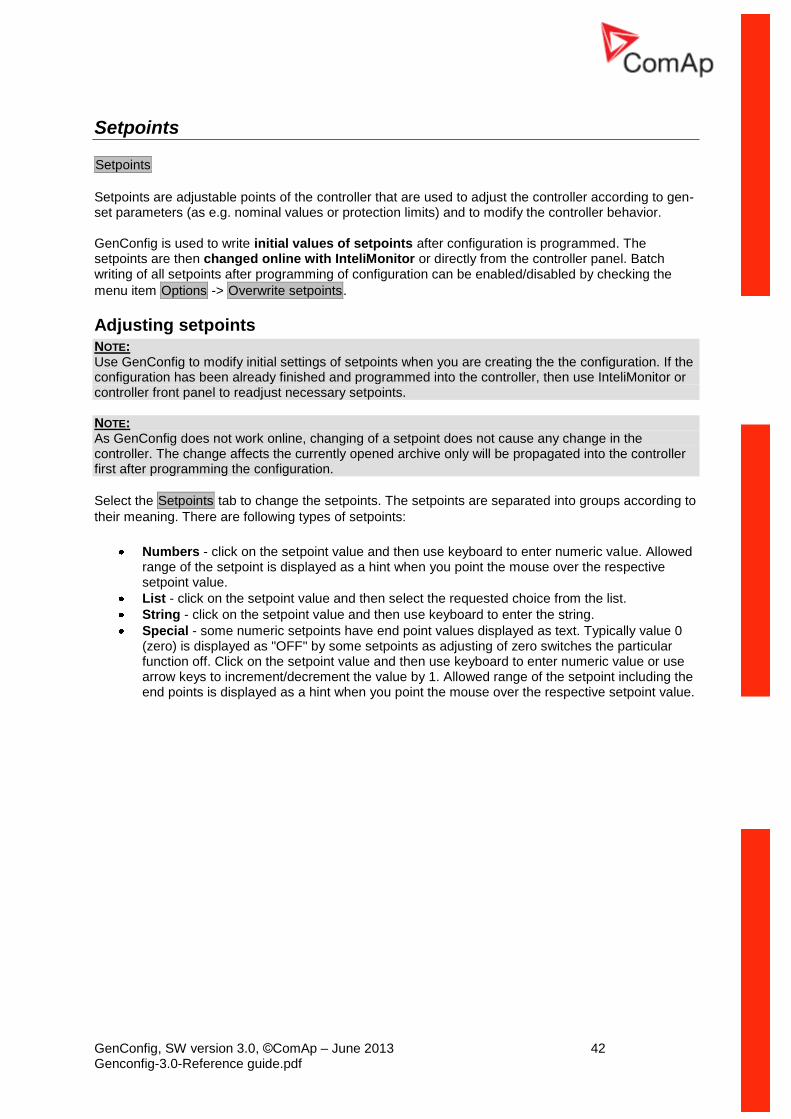
Limits calculator (legacy)
The calculator is used for defining of the linear transformation function if Convert = YES. Enter two
points of the configured value and appropriate output level for each point.
NOTE:
It may occur that you will see "N/A" in the "Computed limits" column and the OK button will be
disabled. That means the particular transformation is not allowed.
TRANSFORMATION OF 0-150KW TO 0-10V RESP. 0-20MA
TRANSFORMATION OF 0-150KW TO 4-20MA
GenConfig, SW version 3.0, ©ComAp – June 2013 42 Genconfig-3.0-Reference guide.pdf
Setpoints
Setpoints
Setpoints are adjustable points of the controller that are used to adjust the controller according to gen-set parameters (as e.g. nominal values or protection limits) and to modify the controller behavior.
GenConfig is used to write initial values of setpoints after configuration is programmed. The setpoints are then changed online with InteliMonitor or directly from the controller panel. Batch writing of all setpoints after programming of configuration can be enabled/disabled by checking the
menu item Options -> Overwrite setpoints.
Adjusting setpoints NOTE: Use GenConfig to modify initial settings of setpoints when you are creating the the configuration. If the configuration has been already finished and programmed into the controller, then use InteliMonitor or controller front panel to readjust necessary setpoints. NOTE: As GenConfig does not work online, changing of a setpoint does not cause any change in the controller. The change affects the currently opened archive only will be propagated into the controller first after programming the configuration.
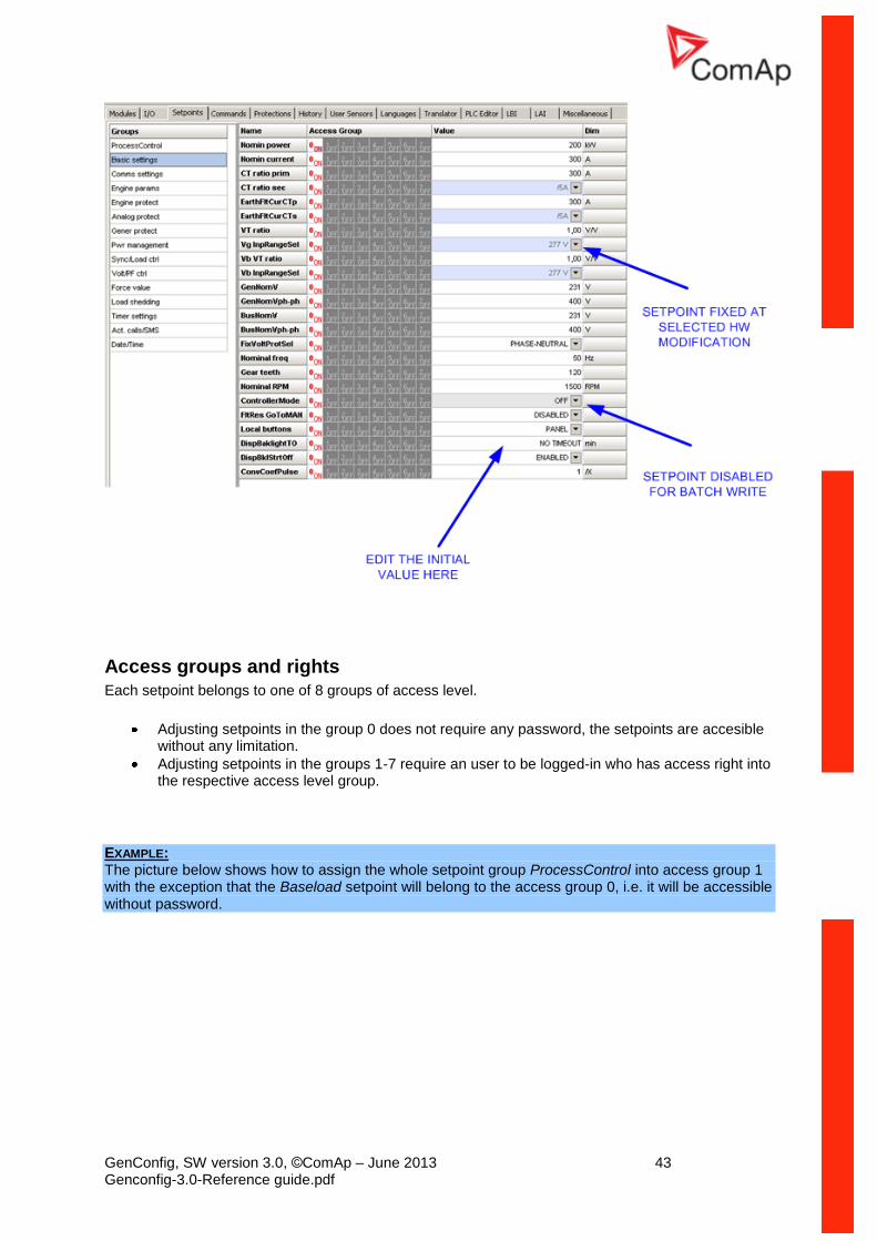
Select the Setpoints tab to change the setpoints. The setpoints are separated into groups according to
their meaning. There are following types of setpoints:
Numbers - click on the setpoint value and then use keyboard to enter numeric value. Allowed range of the setpoint is displayed as a hint when you point the mouse over the respective setpoint value.
List - click on the setpoint value and then select the requested choice from the list.
String - click on the setpoint value and then use keyboard to enter the string.
Special - some numeric setpoints have end point values displayed as text. Typically value 0 (zero) is displayed as "OFF" by some setpoints as adjusting of zero switches the particular function off. Click on the setpoint value and then use keyboard to enter numeric value or use arrow keys to increment/decrement the value by 1. Allowed range of the setpoint including the end points is displayed as a hint when you point the mouse over the respective setpoint value.
GenConfig, SW version 3.0, ©ComAp – June 2013 43 Genconfig-3.0-Reference guide.pdf
Access groups and rights
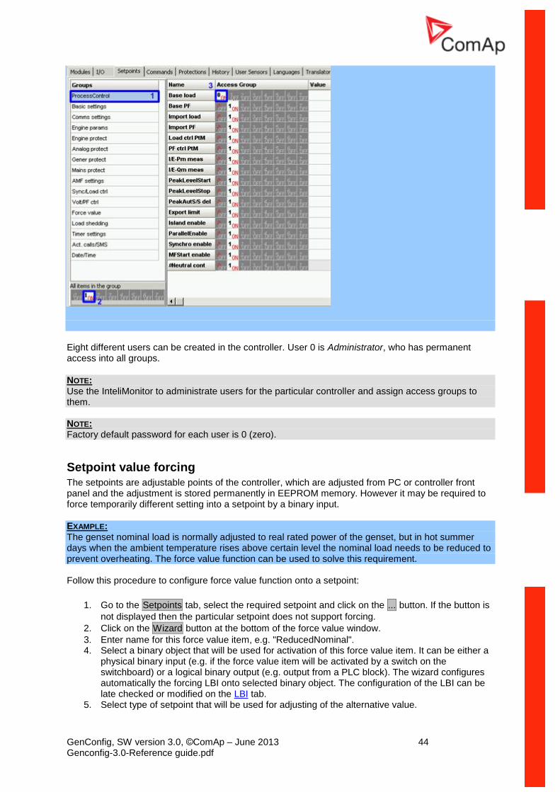
Each setpoint belongs to one of 8 groups of access level.
Adjusting setpoints in the group 0 does not require any password, the setpoints are accesible without any limitation.
Adjusting setpoints in the groups 1-7 require an user to be logged-in who has access right into the respective access level group.
EXAMPLE: The picture below shows how to assign the whole setpoint group ProcessControl into access group 1 with the exception that the Baseload setpoint will belong to the access group 0, i.e. it will be accessible without password.
GenConfig, SW version 3.0, ©ComAp – June 2013 44 Genconfig-3.0-Reference guide.pdf
Eight different users can be created in the controller. User 0 is Administrator, who has permanent access into all groups.
NOTE: Use the InteliMonitor to administrate users for the particular controller and assign access groups to them. NOTE: Factory default password for each user is 0 (zero).
Setpoint value forcing
The setpoints are adjustable points of the controller, which are adjusted from PC or controller front panel and the adjustment is stored permanently in EEPROM memory. However it may be required to force temporarily different setting into a setpoint by a binary input.
EXAMPLE: The genset nominal load is normally adjusted to real rated power of the genset, but in hot summer days when the ambient temperature rises above certain level the nominal load needs to be reduced to prevent overheating. The force value function can be used to solve this requirement. Follow this procedure to configure force value function onto a setpoint:
1. Go to the Setpoints tab, select the required setpoint and click on the ... button. If the button is
not displayed then the particular setpoint does not support forcing.
2. Click on the Wizard button at the bottom of the force value window.
3. Enter name for this force value item, e.g. "ReducedNominal". 4. Select a binary object that will be used for activation of this force value item. It can be either a
physical binary input (e.g. if the force value item will be activated by a switch on the switchboard) or a logical binary output (e.g. output from a PLC block). The wizard configures automatically the forcing LBI onto selected binary object. The configuration of the LBI can be late checked or modified on the LBI tab.
5. Select type of setpoint that will be used for adjusting of the alternative value.
GenConfig, SW version 3.0, ©ComAp – June 2013 45 Genconfig-3.0-Reference guide.pdf
Use Select other object in case you want to force the same alternative value into
more setpoints and you have already defined the forcing setpoint by the previous forcing item.
Use Use default setpoint to create new forcing setpoint.
6. If new forcing setpoint is created then give a suitable name to it (e.g. "Reduced Pnom") and adjust initial value of it.
NOTE: If there are more than one force value blocks configured onto one setpoint then the highest priority has the block with the lowest index (i.e. the first active block according to the list displayed in GenConfig in
the Force value window at the related setpoint).
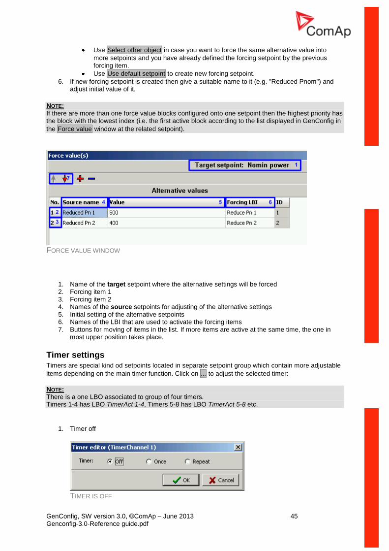
FORCE VALUE WINDOW
1. Name of the target setpoint where the alternative settings will be forced 2. Forcing item 1 3. Forcing item 2 4. Names of the source setpoints for adjusting of the alternative settings 5. Initial setting of the alternative setpoints 6. Names of the LBI that are used to activate the forcing items 7. Buttons for moving of items in the list. If more items are active at the same time, the one in
most upper position takes place.
Timer settings Timers are special kind od setpoints located in separate setpoint group which contain more adjustable
items depending on the main timer function. Click on ... to adjust the selected timer:
NOTE: There is a one LBO associated to group of four timers. Timers 1-4 has LBO TimerAct 1-4, Timers 5-8 has LBO TimerAct 5-8 etc.
1. Timer off
TIMER IS OFF
GenConfig, SW version 3.0, ©ComAp – June 2013 46 Genconfig-3.0-Reference guide.pdf
2. Single activation (one shot)
Adjust date, time and duration (hh:mm) of the timer.
ADJUSTMENT OF AN ONE SHOT TIMER
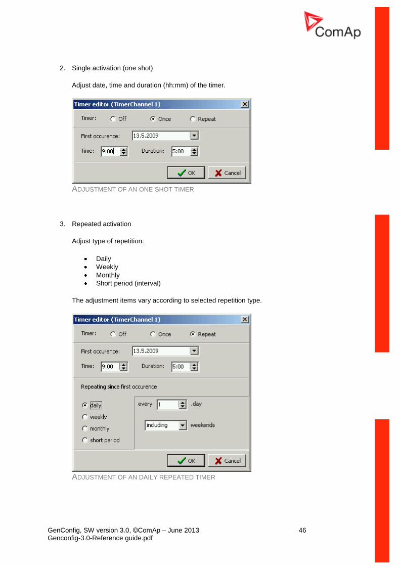
3. Repeated activation
Adjust type of repetition:
Daily
Weekly
Monthly
Short period (interval)
The adjustment items vary according to selected repetition type.
ADJUSTMENT OF AN DAILY REPEATED TIMER
GenConfig, SW version 3.0, ©ComAp – June 2013 47 Genconfig-3.0-Reference guide.pdf
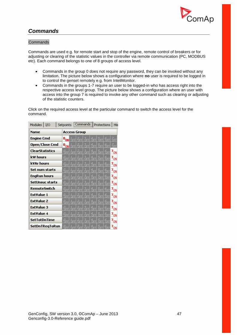
Commands
Commands
Commands are used e.g. for remote start and stop of the engine, remote control of breakers or for adjusting or clearing of the statistic values in the controller via remote communication (PC, MODBUS etc). Each command belongs to one of 8 groups of access level.
Commands in the group 0 does not require any password, they can be invoked without any limitation. The picture below shows a configuration where no user is required to be logged in to control the genset remotely e.g. from InteliMonitor.
Commands in the groups 1-7 require an user to be logged-in who has access right into the respective access level group. The picture below shows a configuration where an user with access into the group 7 is required to invoke any other command such as clearing or adjusting of the statistic counters.
Click on the required access level at the particular command to switch the access level for the command.
GenConfig, SW version 3.0, ©ComAp – June 2013 48 Genconfig-3.0-Reference guide.pdf
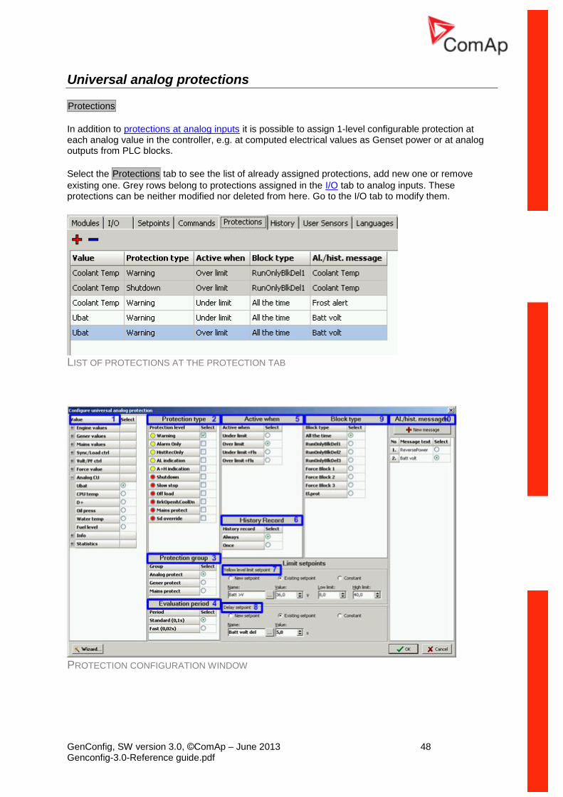
Universal analog protections
Protections
In addition to protections at analog inputs it is possible to assign 1-level configurable protection at each analog value in the controller, e.g. at computed electrical values as Genset power or at analog outputs from PLC blocks.
Select the Protections tab to see the list of already assigned protections, add new one or remove
existing one. Grey rows belong to protections assigned in the I/O tab to analog inputs. These protections can be neither modified nor deleted from here. Go to the I/O tab to modify them.
LIST OF PROTECTIONS AT THE PROTECTION TAB
PROTECTION CONFIGURATION WINDOW
GenConfig, SW version 3.0, ©ComAp – June 2013 49 Genconfig-3.0-Reference guide.pdf
Click on + button and follow instructions below to assign a protection to an analog value:
1. First select the analog value to which the protection will be assigned. 2. Select the protection type. Note that this is 1-level protection so only one protection type from
the list can be selected. For having 2-level protection you need to assign two separate protections with different levels to the same value.
3. Select the group of setpoints, where limit setpoints of the protection will be placed in. 4. Select evaluation period. Use standard (100ms) for all protections except extremely time-
critical protections. 5. Select whether the protection will activate when the analog value gets above the limit or below
the limit.
6. Select how the protection will be recorded into the history log. Once means that only first
occurence of the protection will be recorded until fault reset is pressed, Always means all
occurences will be recorded. 7. Select whether the limit will be constant or adjustable by a setpoint. If setpoint is used it is
possible to create new setpoint or share the setpoint with other protection(s). Sharing of one setpoint among more protections may be helpful e.g. if there are more exhaust temperature sensors in the system and protection limit is same for all of them. If new setpoint is created then change it's name, adjust it's range and initial setting.
8. Select the delay setpoint/constant. Proceed as with the limit setpoint. 9. Select time period while the protection will be enabled. Protections at certain values must be
blocked while the engine is not running. 10. Select the message that will be displayed in the alarmlist and history when the protection
activates. You can either define new message or share message with other protection(s). It is not possible to share the message if is used for another protection of the same level but different type.
ALARM TYPES
ALARM/EVENT KIND LEVEL DESCRIPTION
Warning 1
The alarm appears in the Alarmlist and is recorded into the history log. Activates the output Common Wrn as well as the standard alarm outputs.
Alarm Only 1 The alarm appears only in the Alarmlist. Activates the output Common Al as well as the standard alarm outputs.
HistRecOnly 1 The event is recorded into the history. Activates the output Common Hst for one second. Standard alarm outputs are not activated.
AL indication 1
The event is only indicated in the Alarmlist. It disappear for the alarmist automatically as soon as the cause disappears. Standard alarm outputs are not activated.
A+H indication 1
The event is only indicated in the Alarmlist and recorded into the history log. It disappear for the alarmist automatically as soon as the cause disappears. Standard alarm outputs are not activated.
Shutdown 2 The alarm appears in the Alarmlist and is recorded into the history log. It causes immediate stop of the gen-set without unloading and
GenConfig, SW version 3.0, ©ComAp – June 2013 50 Genconfig-3.0-Reference guide.pdf
cooling phase. The gen-set can't be started again while there is a Shutdown alarm in the Alarmlist. Activates the output Common Sd as well as the standard alarm outputs.
Slow Stop 2
The alarm appears in the Alarmlist and is recorded into the history log. It causes stop of the gen-set by the standard stop sequence, i.e. including unloading and cooling phase. The gen-set can't be started again while there is a Slow stop alarm in the Alarmlist. Activates the output Common Stp as well as the standard alarm outputs.
Off Load 2
The event appears in the Alarmlist and is recorded into the history log. It does not require confirmation, diappears by itself. It causes immediate opening of the GCB. In AUT and SEM modes the genset remains running for 60 seconds and then it is stopped by the standard stop sequence. In MAN mode the gen-set remains running until the operator changes it's operational state manually. If the controller is in AUT or SEM mode and all previously active Off load alarms disappeared the gen-set is automatically started back and connected to the load if the condition for the gen-set to be running persists (e.g. Rem start/stop is active ..). This event is used to put the gen-set temporarily off the load for any reason. Activates the output Common OfL.
Low Power 2
The event appears in the Alarmlist and is recorded into the history log. It does not require confirmation, diappears by itself. It causes reduction of the required gen-set load to the Min Power PtM during parallel-to-mains operation or local baseload operation. If all previously active Low power alarms disappeared the gen-set is automatically ramped back to the original required load, which is given according to the currently active load control mode (Load ctrl PtM) in PtM operation. Activates the output Common LoP. This alarm type is not overriden by the input Sd Override. Note: Available in IS-NT only.
BrkOpen&CoolDn 2
The event appears in the Alarmlist and is recorded into the history log. It causes immediate opening of the GCB (without unloading) and then the standard stop sequence with cooling follows. The gen-set can't be started again while there is a BOC alarm in the Alarmlist. Activates the output Common BOC as well as the standard alarm outputs.
Mains Protect 2
The protection is only recorded into the history log. In applications which control the MCB this protection causes opening of the MCB. The gen-set can continue operation in island mode if required. The MCB can be closed back as soon as there isn't any mains protection active (including the built-in mains protections). In applications which do not control the MCB this protection causes opening of the GCB. The controller waits then for the MCB to open. After that the gen-set can continue operation in
GenConfig, SW version 3.0, ©ComAp – June 2013 51 Genconfig-3.0-Reference guide.pdf
island mode if required. As soon as there isn't any mains protection active (including the built-in mains protections) the GCB is opened again and the controller waits for the MCB to close. After that the gen-set can continue operation in parallel-to-mains mode if required. Activates the output Common MP. This alarm type is not overriden by the input Sd Override.
Sd Override 2
The alarm appears in the Alarmlist and is recorded into the history log. It causes immediate stop of the gen-set without unloading and cooling phase. The gen-set can't be started again while there is a Sd override alarm in the Alarmlist. Activates the standard alarm outputs. This alarm type is not overriden by the input Sd Override.
EXAMPLE: Complex protection - this example shows how to use universal protections to create a complex protection at analog input where coolant temperature is measured. The protection will issue a warning alarm "Frost alert" whenever the temperature drops below 0° (fixed limit) or warning/shutdown alarm "Coolant Temp" when the teperature rises above 95/100° (adjustable). The overtemperature will be checked at running engine only.
1. Go to the I/O tab and configure the appropriate analog input. Give the name "Coolant Temp"
to it, configure appropriate sensor and other items. Tick Protection and configure:
Protection type = Warning, Shutdown
Active when = Over limit
History record = Always
Block type = RunOnlyBlkDel1
Adjust initial values of limit setpoints to 95 and 100°
2. Go to the Protections tab and click on + button to add new protection.
3. Select Coolant Temp value and configure following protection properties:
Protection type = Warning
Protection group = Analog protect
Evaluation period = Standard
Active when = Under limit
Block type = All the time
History record = Always
Press the button New Message and enter text "Frost alert"
Select "Constant" for the limit and delay setpoints and adjust 0° as limit and 10s as delay
EXAMPLE: Window protection - this example shows how to use universal protections to create a window protection for the battery voltage. The protection will issue a warning alarm "Batt volt" whenever the battery voltage drops below 18V or rises above 30V.
1. Go to the Protections tab and click on + button to add new protection.
2. Select UBat value from the Analog CU group and configure following protection properties:
Protection type = Warning
Protection group = Analog protect
GenConfig, SW version 3.0, ©ComAp – June 2013 52 Genconfig-3.0-Reference guide.pdf
Evaluation period = Standard
Active when = Under limit
Block type = All the time
History record = Always
Press the button New Message and enter text "Batt Volt"
Select "New setpoint" for the limit setpoint, give name "Batt Volt <" to it, adjust range 0 - 20V and adjust the limit to 18V
Select "New setpoint" for the delay setpoint, give name "Batt Volt Del" to it and adjust the delay to 10s
3. Click on + button again to add new protection.
4. Select UBat value from the Analog CU group and configure following protection properties:
Protection type = Warning
Protection group = Analog protect
Evaluation period = Standard
Active when = Over limit
Block type = All the time
History record = Always
Message = "Batt Volt"
Select "New setpoint" for the limit setpoint, give name "Batt Volt >" to it, adjust range 20 - 40V and adjust the limit to 30V
Select "Existing setpoint" for the delay setpoint and select the previously created "Batt Volt Del" setpoint.
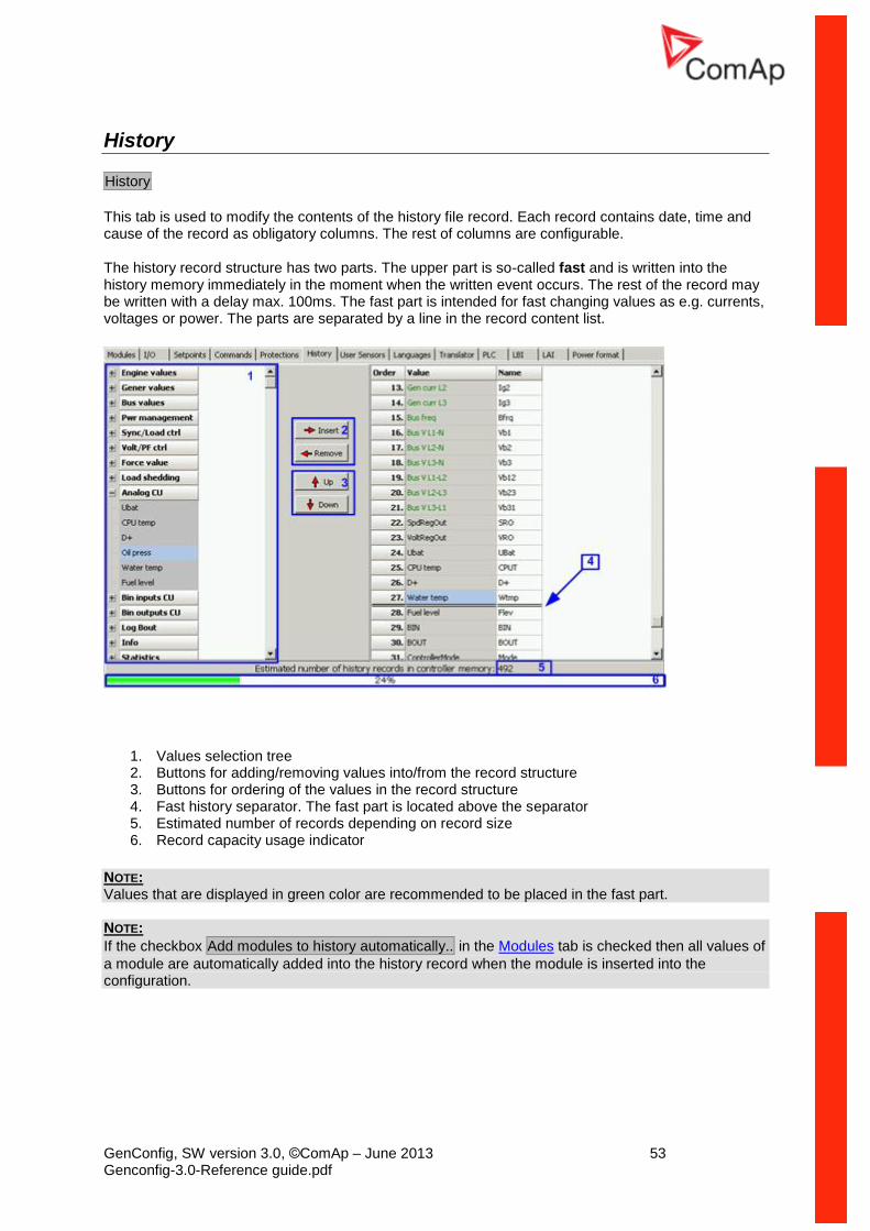
GenConfig, SW version 3.0, ©ComAp – June 2013 53 Genconfig-3.0-Reference guide.pdf
History
History
This tab is used to modify the contents of the history file record. Each record contains date, time and cause of the record as obligatory columns. The rest of columns are configurable.
The history record structure has two parts. The upper part is so-called fast and is written into the history memory immediately in the moment when the written event occurs. The rest of the record may be written with a delay max. 100ms. The fast part is intended for fast changing values as e.g. currents, voltages or power. The parts are separated by a line in the record content list.
1. Values selection tree 2. Buttons for adding/removing values into/from the record structure 3. Buttons for ordering of the values in the record structure 4. Fast history separator. The fast part is located above the separator 5. Estimated number of records depending on record size 6. Record capacity usage indicator
NOTE: Values that are displayed in green color are recommended to be placed in the fast part. NOTE:
If the checkbox Add modules to history automatically.. in the Modules tab is checked then all values of
a module are automatically added into the history record when the module is inserted into the configuration.
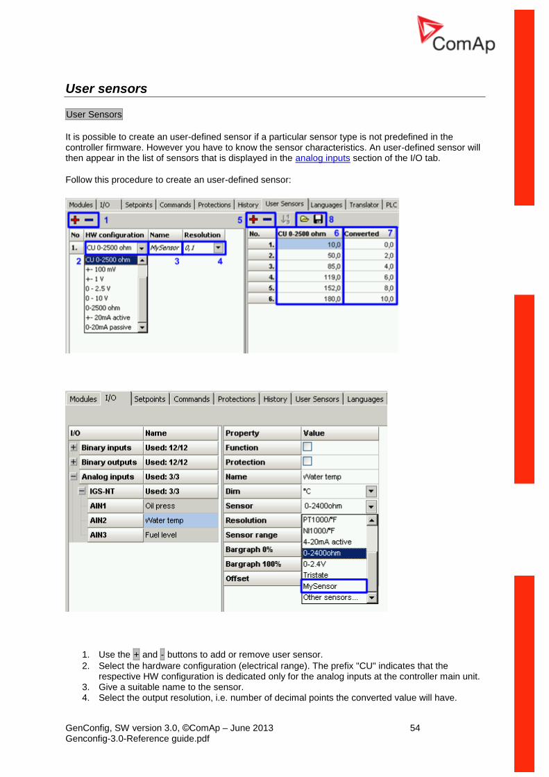
GenConfig, SW version 3.0, ©ComAp – June 2013 54 Genconfig-3.0-Reference guide.pdf
User sensors
User Sensors
It is possible to create an user-defined sensor if a particular sensor type is not predefined in the controller firmware. However you have to know the sensor characteristics. An user-defined sensor will then appear in the list of sensors that is displayed in the analog inputs section of the I/O tab.
Follow this procedure to create an user-defined sensor:
1. Use the + and - buttons to add or remove user sensor.
2. Select the hardware configuration (electrical range). The prefix "CU" indicates that the respective HW configuration is dedicated only for the analog inputs at the controller main unit.
3. Give a suitable name to the sensor. 4. Select the output resolution, i.e. number of decimal points the converted value will have.
GenConfig, SW version 3.0, ©ComAp – June 2013 55 Genconfig-3.0-Reference guide.pdf
5. Create appropriate number of the points of the sensor characteristics. 6. Fill-in the input values of each point, e.g. mA, V, Ohm etc. 7. Fill-in the output values of each point, e.g. °C, Bar, kPa, % etc. 8. The points can be loaded from a *.crv file from disk or saved to a file to disk.
The sensor will now appear in the list of sensors that is displayed in the analog inputs section of the I/O tab.
GenConfig, SW version 3.0, ©ComAp – June 2013 56 Genconfig-3.0-Reference guide.pdf
Languages and Translator
The controller can contain texts in more different languages. The number of slots available for additional languages depends on the number of texts used in the configuration (i.e. on the application complexity, ECU size, number of extension modules etc..).
NOTE: The language slot #1 is not changeable and always contains english. The procedure of adding a new language consists of two steps:
1. Create new language 2. Translate the texts
Create language
Languages
Creating a language:
Use the - button to remove all unnecessary additional languages. If you want to create a
"graphical" language which uses large font (Korean, Chinese etc.), do not remove existing large font based language with unicode flag.
Click to the + button (1) and create new language. If you want to create a latin language,
select English as the base language. If you want to create graphical one, select an existing graphical language as e.g. Chinese or "englishL" (2) as the base language.
Then give a suitable name (3) to the language and select locale ID (4) and time/date format (5). Code page will be completed automatically after locale ID is selected.
Now you can remove the original graphical language, which was used as the base language.
Continue to the Translator tab to translate the texts from English to the target language.
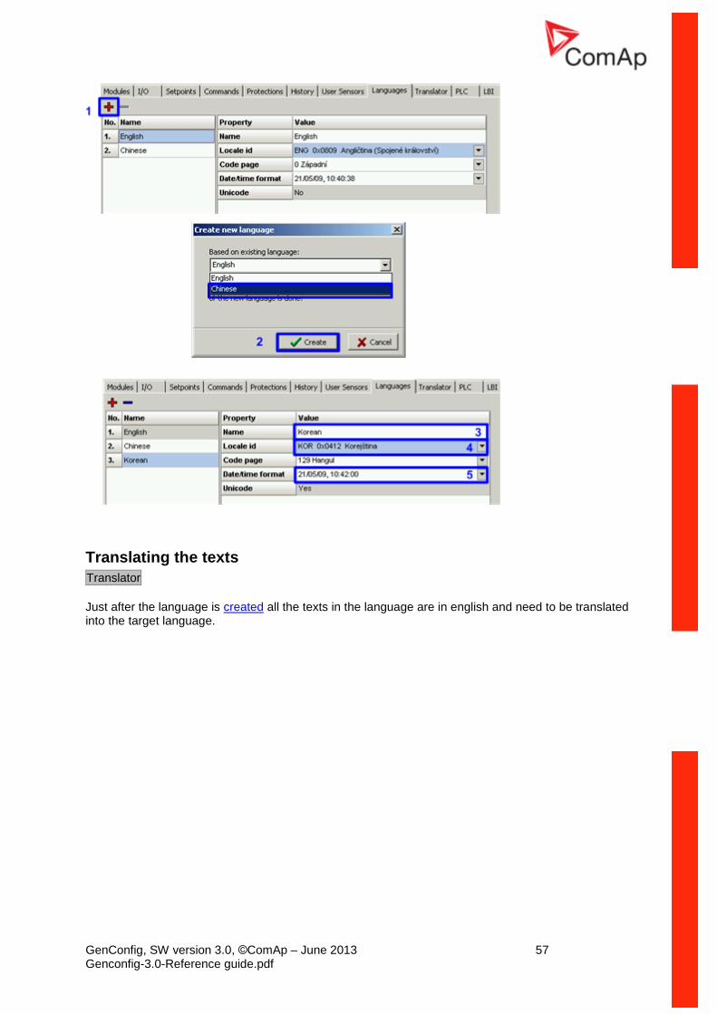
GenConfig, SW version 3.0, ©ComAp – June 2013 57 Genconfig-3.0-Reference guide.pdf
Translating the texts
Translator
Just after the language is created all the texts in the language are in english and need to be translated into the target language.
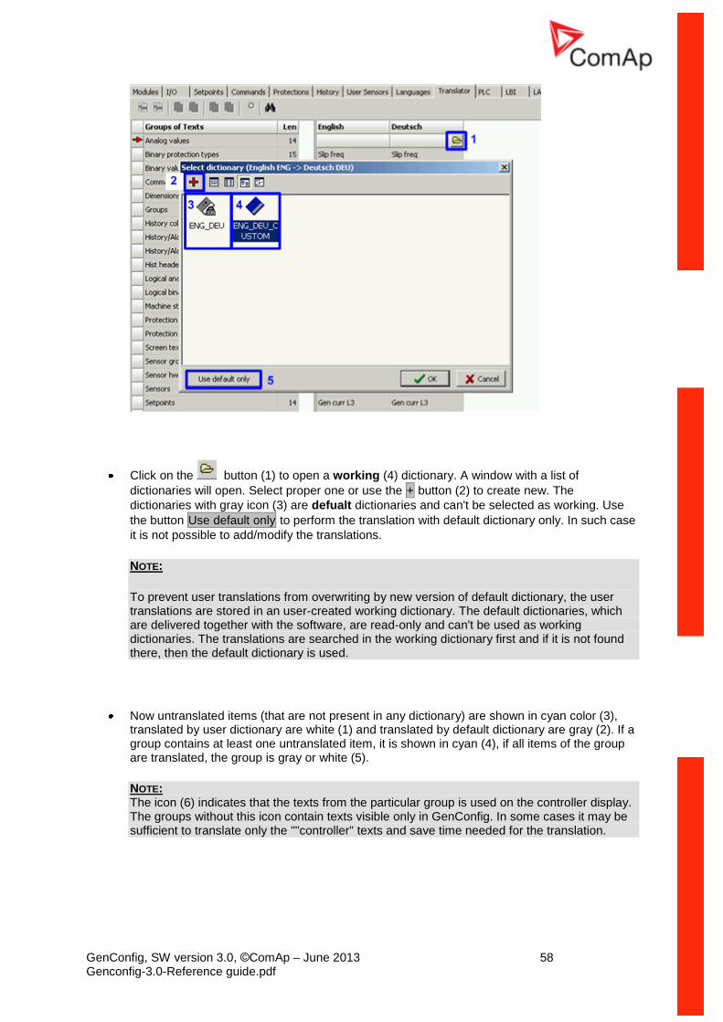
GenConfig, SW version 3.0, ©ComAp – June 2013 58 Genconfig-3.0-Reference guide.pdf
Click on the button (1) to open a working (4) dictionary. A window with a list of
dictionaries will open. Select proper one or use the + button (2) to create new. The
dictionaries with gray icon (3) are defualt dictionaries and can't be selected as working. Use
the button Use default only to perform the translation with default dictionary only. In such case
it is not possible to add/modify the translations.
NOTE:
To prevent user translations from overwriting by new version of default dictionary, the user translations are stored in an user-created working dictionary. The default dictionaries, which are delivered together with the software, are read-only and can't be used as working dictionaries. The translations are searched in the working dictionary first and if it is not found there, then the default dictionary is used.
Now untranslated items (that are not present in any dictionary) are shown in cyan color (3), translated by user dictionary are white (1) and translated by default dictionary are gray (2). If a group contains at least one untranslated item, it is shown in cyan (4), if all items of the group are translated, the group is gray or white (5).
NOTE: The icon (6) indicates that the texts from the particular group is used on the controller display. The groups without this icon contain texts visible only in GenConfig. In some cases it may be sufficient to translate only the ""controller" texts and save time needed for the translation.
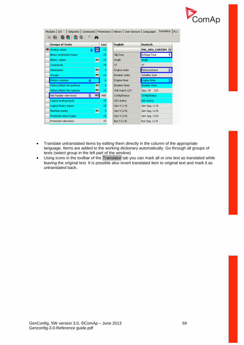
GenConfig, SW version 3.0, ©ComAp – June 2013 59 Genconfig-3.0-Reference guide.pdf
Translate untranslated items by editing them directly in the column of the appropriate language. Items are added to the working dictionary automatically. Go through all groups of texts (select group in the left part of the window)
Using icons in the toolbar of the Translator tab you can mark all or one text as translated while
leaving the original text. It is possible also revert translated item to original text and mark it as untranslated back.
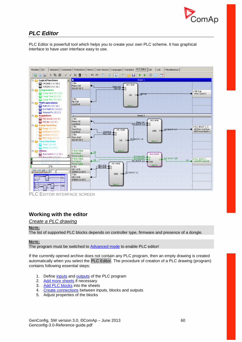
GenConfig, SW version 3.0, ©ComAp – June 2013 60 Genconfig-3.0-Reference guide.pdf
PLC Editor
PLC Editor is powerfull tool which helps you to create your own PLC scheme. It has graphical interface to have user interface easy to use.
PLC EDITOR INTERFACE SCREEN
Working with the editor
Create a PLC drawing
NOTE: The list of supported PLC blocks depends on controller type, firmware and presence of a dongle. NOTE: The program must be switched to Advanced mode to enable PLC editor! If the currently opened archive does not contain any PLC program, then an empty drawing is created
automatically when you select the PLC Editor. The procedure of creation of a PLC drawing (program)
contains following essential steps:
1. Define inputs and outputs of the PLC program 2. Add more sheets if necessary 3. Add PLC blocks into the sheets 4. Create connections between inputs, blocks and outputs 5. Adjust properties of the blocks
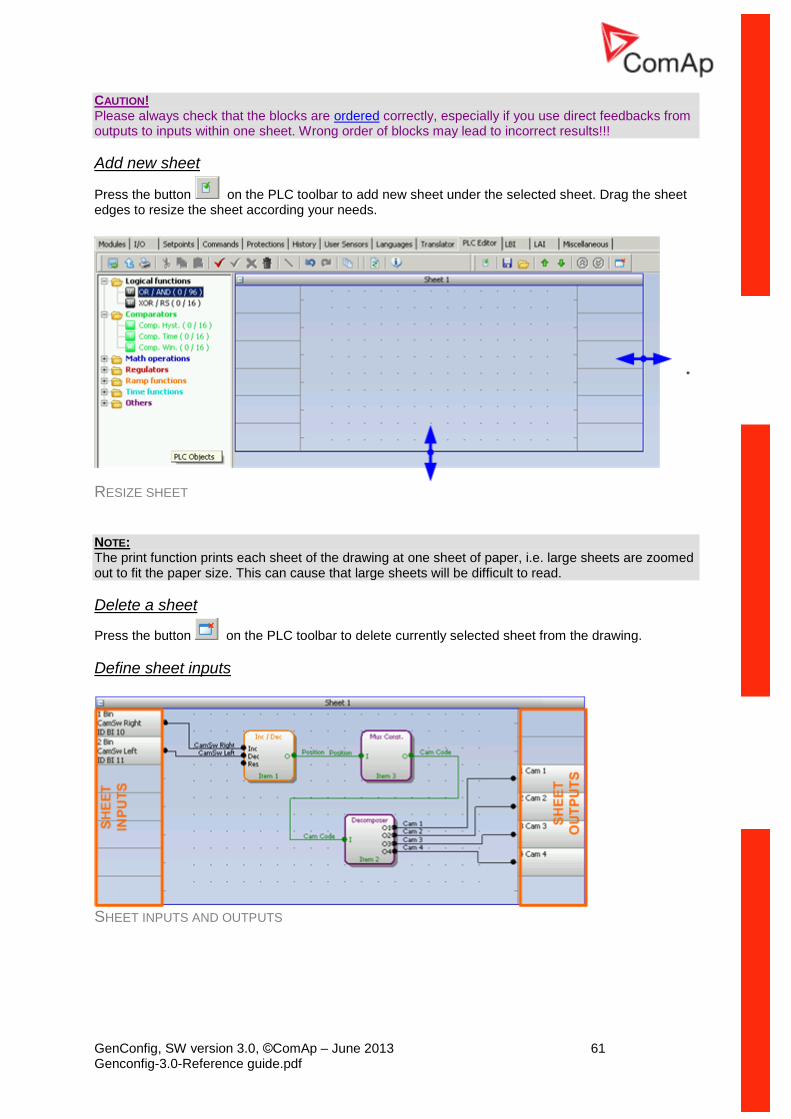
GenConfig, SW version 3.0, ©ComAp – June 2013 61 Genconfig-3.0-Reference guide.pdf
CAUTION! Please always check that the blocks are ordered correctly, especially if you use direct feedbacks from outputs to inputs within one sheet. Wrong order of blocks may lead to incorrect results!!!
Add new sheet
Press the button on the PLC toolbar to add new sheet under the selected sheet. Drag the sheet edges to resize the sheet according your needs.
RESIZE SHEET
NOTE: The print function prints each sheet of the drawing at one sheet of paper, i.e. large sheets are zoomed out to fit the paper size. This can cause that large sheets will be difficult to read.
Delete a sheet
Press the button on the PLC toolbar to delete currently selected sheet from the drawing.
Define sheet inputs
SHEET INPUTS AND OUTPUTS
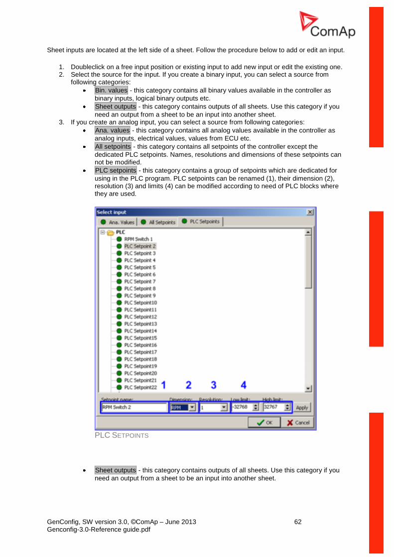
GenConfig, SW version 3.0, ©ComAp – June 2013 62 Genconfig-3.0-Reference guide.pdf
Sheet inputs are located at the left side of a sheet. Follow the procedure below to add or edit an input.
1. Doubleclick on a free input position or existing input to add new input or edit the existing one. 2. Select the source for the input. If you create a binary input, you can select a source from
following categories:
Bin. values - this category contains all binary values available in the controller as
binary inputs, logical binary outputs etc.
Sheet outputs - this category contains outputs of all sheets. Use this category if you
need an output from a sheet to be an input into another sheet. 3. If you create an analog input, you can select a source from following categories:
Ana. values - this category contains all analog values available in the controller as
analog inputs, electrical values, values from ECU etc.
All setpoints - this category contains all setpoints of the controller except the
dedicated PLC setpoints. Names, resolutions and dimensions of these setpoints can not be modified.
PLC setpoints - this category contains a group of setpoints which are dedicated for
using in the PLC program. PLC setpoints can be renamed (1), their dimension (2), resolution (3) and limits (4) can be modified according to need of PLC blocks where they are used.
PLC SETPOINTS
Sheet outputs - this category contains outputs of all sheets. Use this category if you
need an output from a sheet to be an input into another sheet.
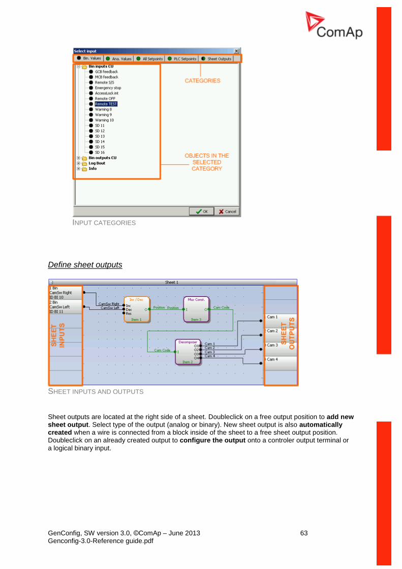
GenConfig, SW version 3.0, ©ComAp – June 2013 63 Genconfig-3.0-Reference guide.pdf
INPUT CATEGORIES
Define sheet outputs
SHEET INPUTS AND OUTPUTS
Sheet outputs are located at the right side of a sheet. Doubleclick on a free output position to add new sheet output. Select type of the output (analog or binary). New sheet output is also automatically created when a wire is connected from a block inside of the sheet to a free sheet output position. Doubleclick on an already created output to configure the output onto a controler output terminal or a logical binary input.
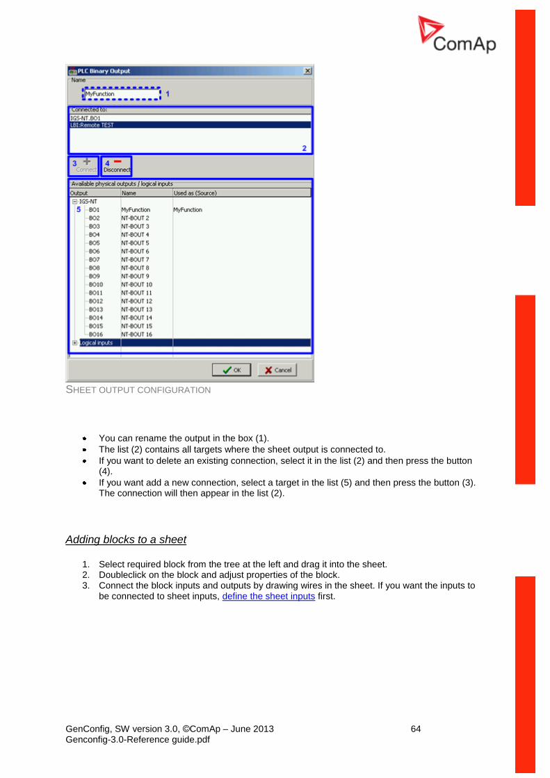
GenConfig, SW version 3.0, ©ComAp – June 2013 64 Genconfig-3.0-Reference guide.pdf
SHEET OUTPUT CONFIGURATION
You can rename the output in the box (1).
The list (2) contains all targets where the sheet output is connected to.
If you want to delete an existing connection, select it in the list (2) and then press the button (4).
If you want add a new connection, select a target in the list (5) and then press the button (3). The connection will then appear in the list (2).
Adding blocks to a sheet
1. Select required block from the tree at the left and drag it into the sheet. 2. Doubleclick on the block and adjust properties of the block. 3. Connect the block inputs and outputs by drawing wires in the sheet. If you want the inputs to
be connected to sheet inputs, define the sheet inputs first.
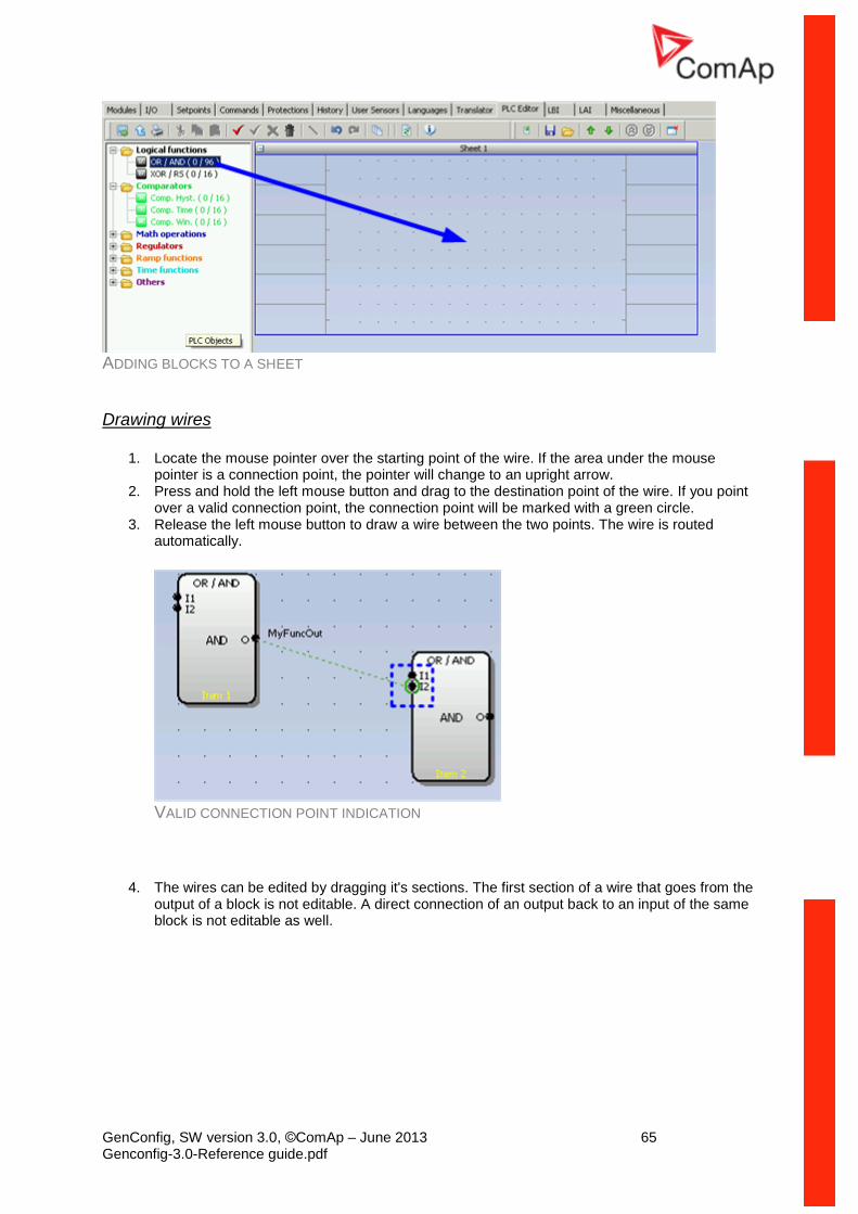
GenConfig, SW version 3.0, ©ComAp – June 2013 65 Genconfig-3.0-Reference guide.pdf
ADDING BLOCKS TO A SHEET
Drawing wires
1. Locate the mouse pointer over the starting point of the wire. If the area under the mouse pointer is a connection point, the pointer will change to an upright arrow.
2. Press and hold the left mouse button and drag to the destination point of the wire. If you point over a valid connection point, the connection point will be marked with a green circle.
3. Release the left mouse button to draw a wire between the two points. The wire is routed automatically.
VALID CONNECTION POINT INDICATION
4. The wires can be edited by dragging it's sections. The first section of a wire that goes from the output of a block is not editable. A direct connection of an output back to an input of the same block is not editable as well.
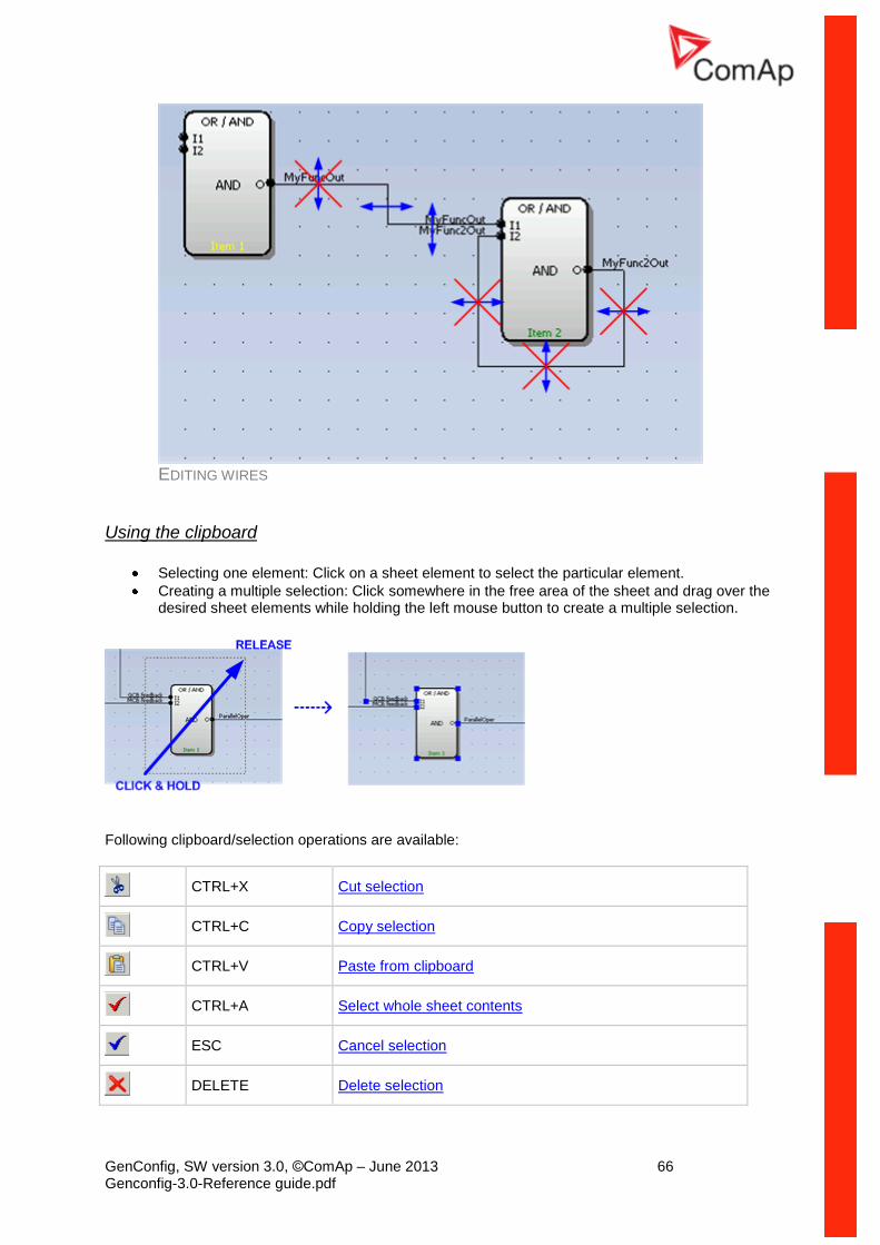
GenConfig, SW version 3.0, ©ComAp – June 2013 66 Genconfig-3.0-Reference guide.pdf
EDITING WIRES
Using the clipboard
Selecting one element: Click on a sheet element to select the particular element.
Creating a multiple selection: Click somewhere in the free area of the sheet and drag over the desired sheet elements while holding the left mouse button to create a multiple selection.
Following clipboard/selection operations are available:
CTRL+X Cut selection
CTRL+C Copy selection
CTRL+V Paste from clipboard
CTRL+A Select whole sheet contents
ESC Cancel selection
DELETE Delete selection
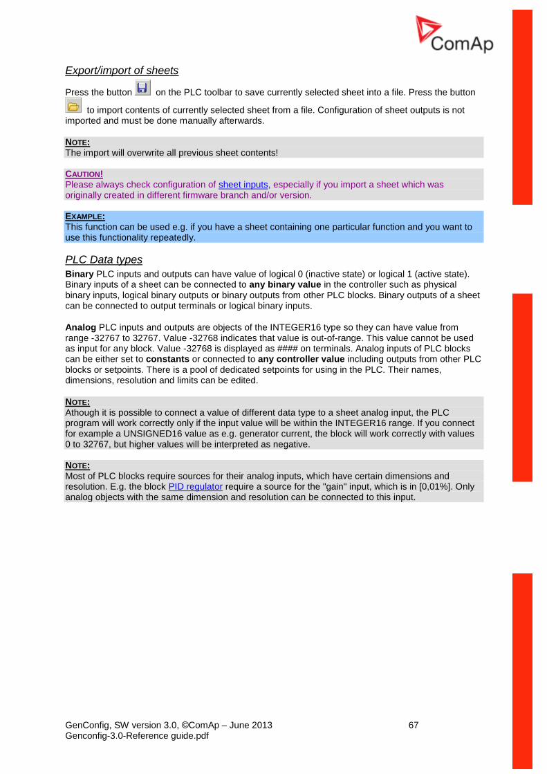
GenConfig, SW version 3.0, ©ComAp – June 2013 67 Genconfig-3.0-Reference guide.pdf
Export/import of sheets
Press the button on the PLC toolbar to save currently selected sheet into a file. Press the button
to import contents of currently selected sheet from a file. Configuration of sheet outputs is not imported and must be done manually afterwards.
NOTE: The import will overwrite all previous sheet contents! CAUTION! Please always check configuration of sheet inputs, especially if you import a sheet which was originally created in different firmware branch and/or version. EXAMPLE: This function can be used e.g. if you have a sheet containing one particular function and you want to use this functionality repeatedly.
PLC Data types
Binary PLC inputs and outputs can have value of logical 0 (inactive state) or logical 1 (active state). Binary inputs of a sheet can be connected to any binary value in the controller such as physical binary inputs, logical binary outputs or binary outputs from other PLC blocks. Binary outputs of a sheet can be connected to output terminals or logical binary inputs.
Analog PLC inputs and outputs are objects of the INTEGER16 type so they can have value from range -32767 to 32767. Value -32768 indicates that value is out-of-range. This value cannot be used as input for any block. Value -32768 is displayed as #### on terminals. Analog inputs of PLC blocks can be either set to constants or connected to any controller value including outputs from other PLC blocks or setpoints. There is a pool of dedicated setpoints for using in the PLC. Their names, dimensions, resolution and limits can be edited.
NOTE: Athough it is possible to connect a value of different data type to a sheet analog input, the PLC program will work correctly only if the input value will be within the INTEGER16 range. If you connect for example a UNSIGNED16 value as e.g. generator current, the block will work correctly with values 0 to 32767, but higher values will be interpreted as negative. NOTE: Most of PLC blocks require sources for their analog inputs, which have certain dimensions and resolution. E.g. the block PID regulator require a source for the "gain" input, which is in [0,01%]. Only analog objects with the same dimension and resolution can be connected to this input.
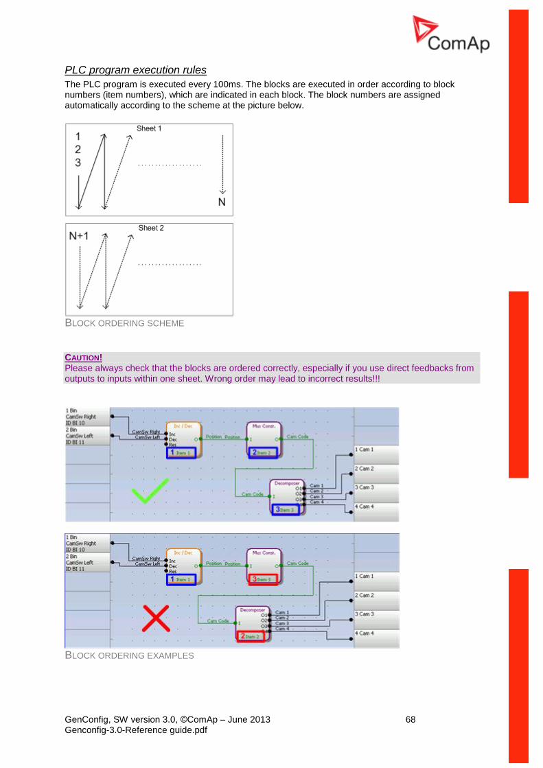
GenConfig, SW version 3.0, ©ComAp – June 2013 68 Genconfig-3.0-Reference guide.pdf
PLC program execution rules
The PLC program is executed every 100ms. The blocks are executed in order according to block numbers (item numbers), which are indicated in each block. The block numbers are assigned automatically according to the scheme at the picture below.
BLOCK ORDERING SCHEME
CAUTION! Please always check that the blocks are ordered correctly, especially if you use direct feedbacks from outputs to inputs within one sheet. Wrong order may lead to incorrect results!!!
BLOCK ORDERING EXAMPLES
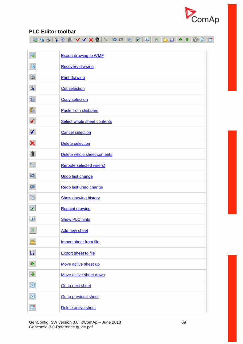
GenConfig, SW version 3.0, ©ComAp – June 2013 69 Genconfig-3.0-Reference guide.pdf
PLC Editor toolbar
Export drawing to WMF
Recovery drawing
Print drawing
Cut selection
Copy selection
Paste from clipboard
Select whole sheet contents
Cancel selection
Delete selection
Delete whole sheet contents
Reroute selected wire(s)
Undo last change
Redo last undo change
Show drawing history
Repaint drawing
Show PLC hints
Add new sheet
Import sheet from file
Export sheet to file
Move active sheet up
Move active sheet down
Go to next sheet
Go to previous sheet
Delete active sheet
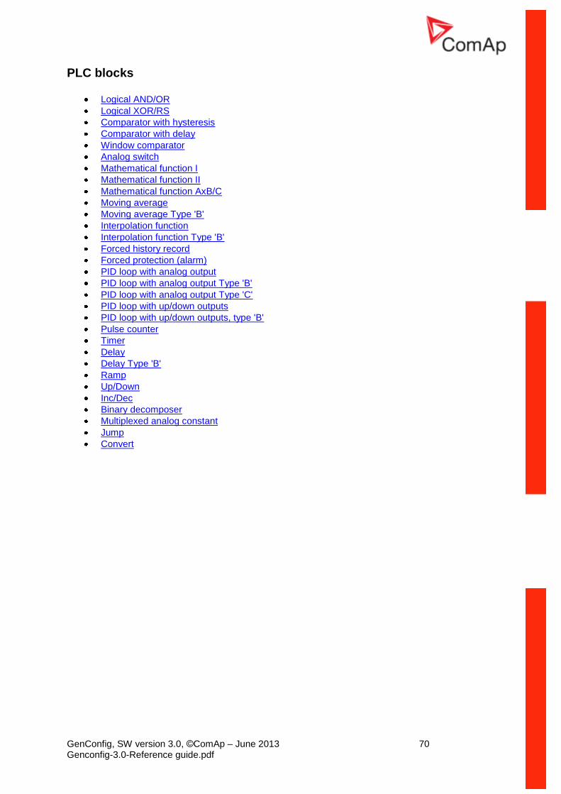
GenConfig, SW version 3.0, ©ComAp – June 2013 70 Genconfig-3.0-Reference guide.pdf
PLC blocks
Logical AND/OR
Logical XOR/RS
Comparator with hysteresis
Comparator with delay
Window comparator
Analog switch
Mathematical function I
Mathematical function II
Mathematical function AxB/C
Moving average
Moving average Type 'B'
Interpolation function
Interpolation function Type 'B'
Forced history record
Forced protection (alarm)
PID loop with analog output
PID loop with analog output Type 'B'
PID loop with analog output Type 'C'
PID loop with up/down outputs
PID loop with up/down outputs, type 'B'
Pulse counter
Timer
Delay
Delay Type 'B'
Ramp
Up/Down
Inc/Dec
Binary decomposer
Multiplexed analog constant
Jump
Convert
GenConfig, SW version 3.0, ©ComAp – June 2013 71 Genconfig-3.0-Reference guide.pdf
InteliVision Screen Editor
The ScreenEditor is an integrated function into GenConfig which allows the user to modify the layout of the screens in the metering mode of Intelivision-8 and/or InteliVision-5.
ScreenEditor is available only in Advanced mode and only for archives IG/IS-NT-2.6 and above.
NOTE:
There is a separate help for the ScreenEditor available in the menu Help.
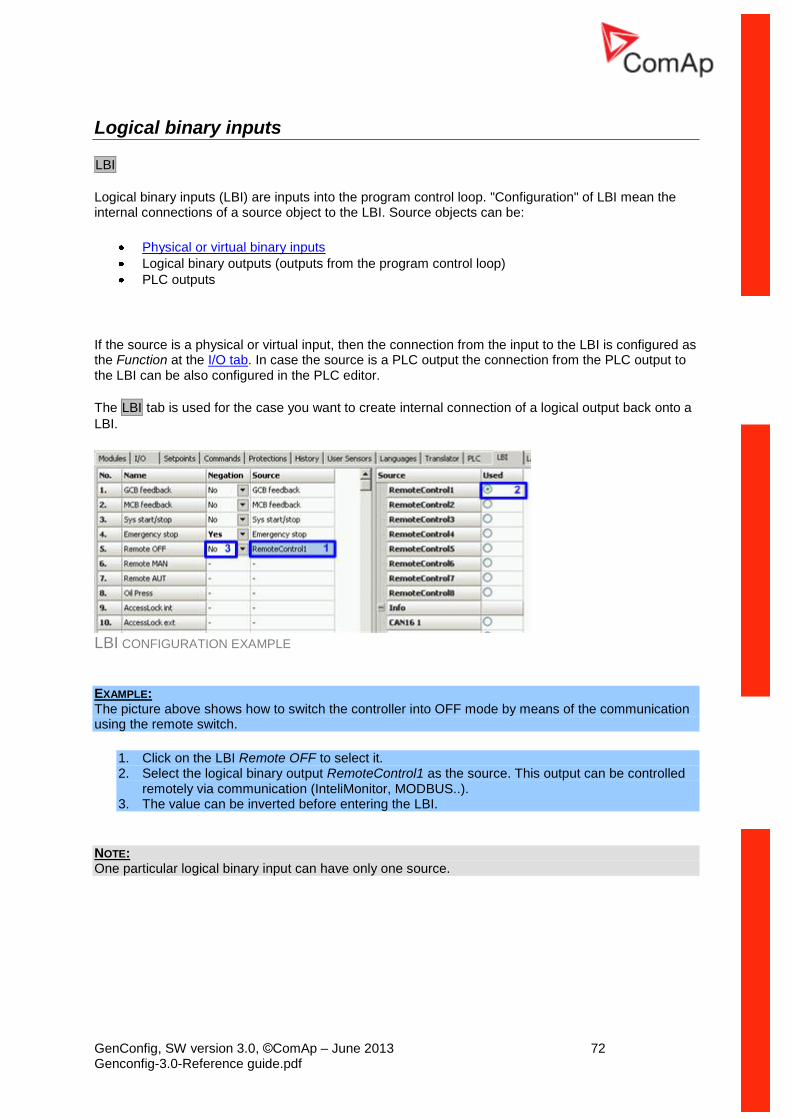
GenConfig, SW version 3.0, ©ComAp – June 2013 72 Genconfig-3.0-Reference guide.pdf
Logical binary inputs
LBI
Logical binary inputs (LBI) are inputs into the program control loop. "Configuration" of LBI mean the internal connections of a source object to the LBI. Source objects can be:
Physical or virtual binary inputs
Logical binary outputs (outputs from the program control loop)
PLC outputs
If the source is a physical or virtual input, then the connection from the input to the LBI is configured as the Function at the I/O tab. In case the source is a PLC output the connection from the PLC output to the LBI can be also configured in the PLC editor.
The LBI tab is used for the case you want to create internal connection of a logical output back onto a
LBI.
LBI CONFIGURATION EXAMPLE
EXAMPLE: The picture above shows how to switch the controller into OFF mode by means of the communication using the remote switch.
1. Click on the LBI Remote OFF to select it. 2. Select the logical binary output RemoteControl1 as the source. This output can be controlled
remotely via communication (InteliMonitor, MODBUS..). 3. The value can be inverted before entering the LBI.
NOTE: One particular logical binary input can have only one source.
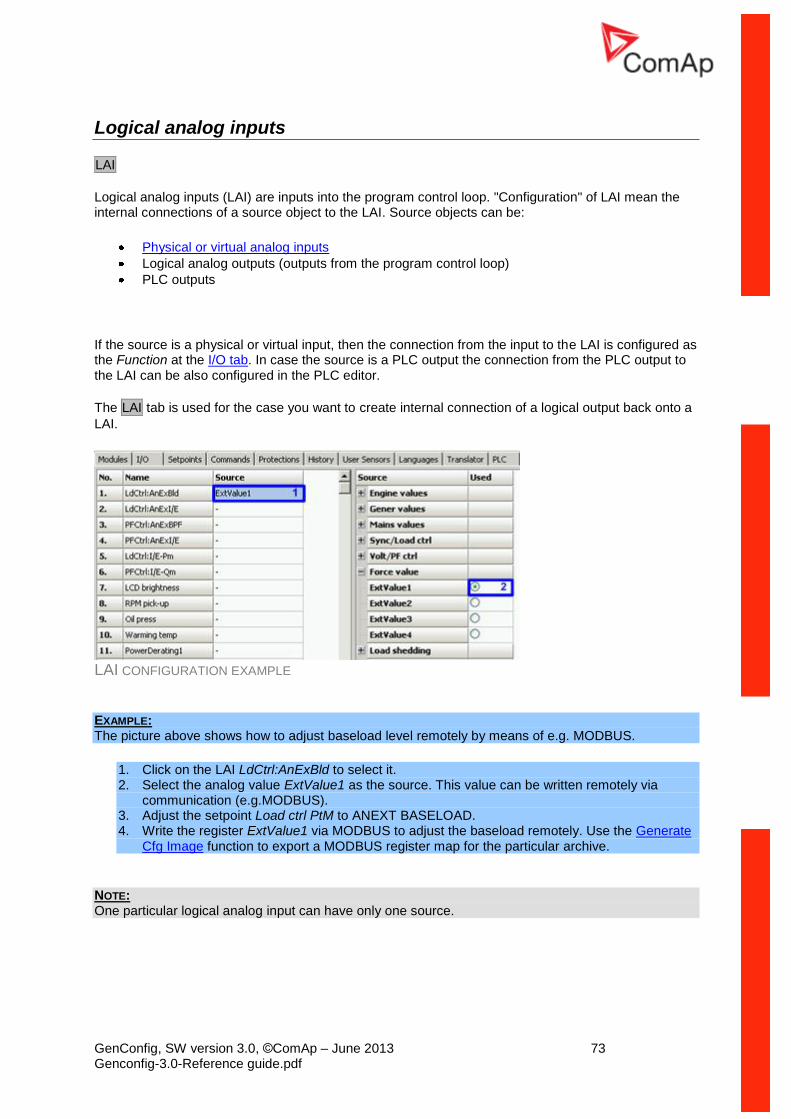
GenConfig, SW version 3.0, ©ComAp – June 2013 73 Genconfig-3.0-Reference guide.pdf
Logical analog inputs
LAI
Logical analog inputs (LAI) are inputs into the program control loop. "Configuration" of LAI mean the internal connections of a source object to the LAI. Source objects can be:
Physical or virtual analog inputs
Logical analog outputs (outputs from the program control loop)
PLC outputs
If the source is a physical or virtual input, then the connection from the input to the LAI is configured as the Function at the I/O tab. In case the source is a PLC output the connection from the PLC output to the LAI can be also configured in the PLC editor.
The LAI tab is used for the case you want to create internal connection of a logical output back onto a
LAI.
LAI CONFIGURATION EXAMPLE
EXAMPLE: The picture above shows how to adjust baseload level remotely by means of e.g. MODBUS.
1. Click on the LAI LdCtrl:AnExBld to select it. 2. Select the analog value ExtValue1 as the source. This value can be written remotely via
communication (e.g.MODBUS). 3. Adjust the setpoint Load ctrl PtM to ANEXT BASELOAD. 4. Write the register ExtValue1 via MODBUS to adjust the baseload remotely. Use the Generate
Cfg Image function to export a MODBUS register map for the particular archive.
NOTE: One particular logical analog input can have only one source.
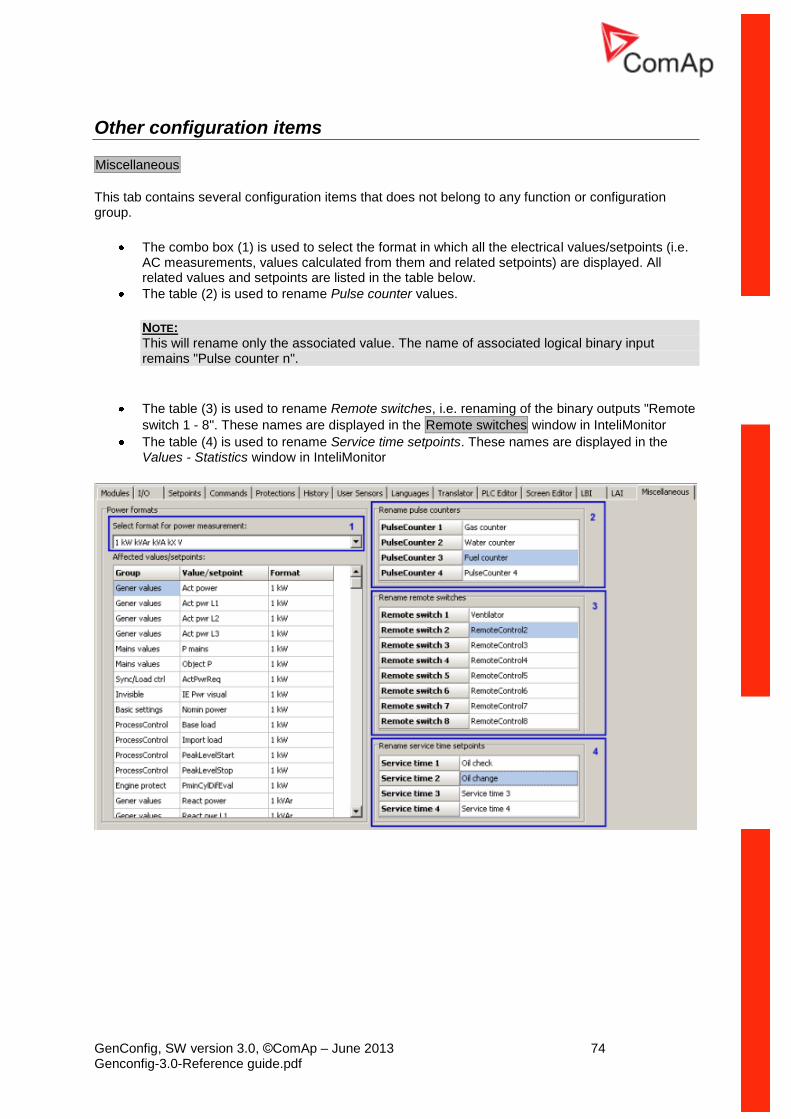
GenConfig, SW version 3.0, ©ComAp – June 2013 74 Genconfig-3.0-Reference guide.pdf
Other configuration items
Miscellaneous
This tab contains several configuration items that does not belong to any function or configuration group.
The combo box (1) is used to select the format in which all the electrical values/setpoints (i.e. AC measurements, values calculated from them and related setpoints) are displayed. All related values and setpoints are listed in the table below.
The table (2) is used to rename Pulse counter values.
NOTE: This will rename only the associated value. The name of associated logical binary input remains "Pulse counter n".
The table (3) is used to rename Remote switches, i.e. renaming of the binary outputs "Remote
switch 1 - 8". These names are displayed in the Remote switches window in InteliMonitor
The table (4) is used to rename Service time setpoints. These names are displayed in the Values - Statistics window in InteliMonitor
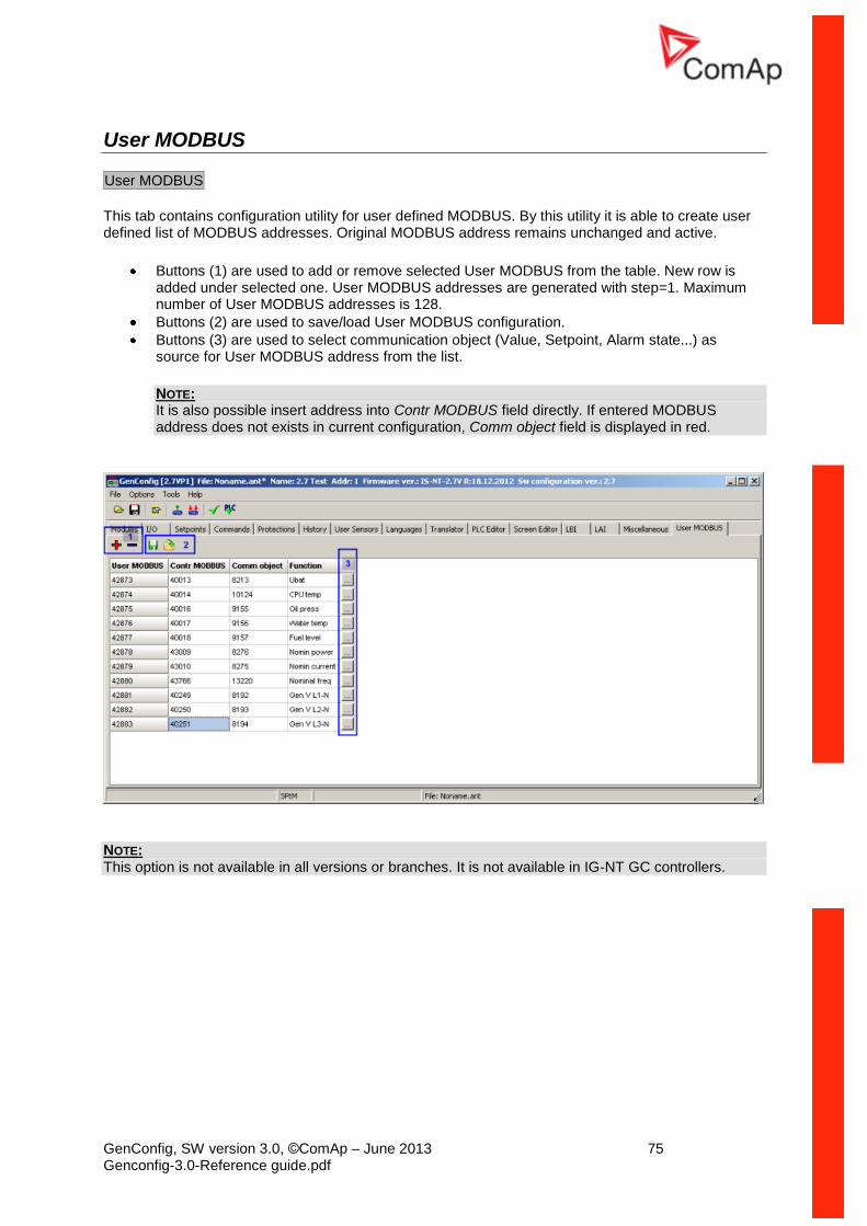
GenConfig, SW version 3.0, ©ComAp – June 2013 75 Genconfig-3.0-Reference guide.pdf
User MODBUS
User MODBUS
This tab contains configuration utility for user defined MODBUS. By this utility it is able to create user defined list of MODBUS addresses. Original MODBUS address remains unchanged and active.
Buttons (1) are used to add or remove selected User MODBUS from the table. New row is added under selected one. User MODBUS addresses are generated with step=1. Maximum number of User MODBUS addresses is 128.
Buttons (2) are used to save/load User MODBUS configuration.
Buttons (3) are used to select communication object (Value, Setpoint, Alarm state...) as source for User MODBUS address from the list.
NOTE: It is also possible insert address into Contr MODBUS field directly. If entered MODBUS address does not exists in current configuration, Comm object field is displayed in red.
NOTE: This option is not available in all versions or branches. It is not available in IG-NT GC controllers.
GenConfig, SW version 3.0, ©ComAp – June 2013 76 Genconfig-3.0-Reference guide.pdf
Menu description
File menu
Open archive from disk
Click to icon or select File -> Open to activate a dialog for opening an archive.
The default archives are located in shared documents folder: C:\Documents and Settings\All Users\Documents\ComAp PC Suite\GenConfig\Archives\Default
The user created archives are intended to be in shared documents folder as well: C:\Documents
and Settings\All Users\Documents\ComAp PC Suite\GenConfig\Archives, however
they can be read from anywhere in the computer.
Save archive to disk
Click to icon or use File -> Save to save the archive to disk. If a filename is not assigned to the
archive yet, you will be asked for it, otherwise the archive will be saved under the assigned filename.
Use File -> Save As to save the archive under different filename.
Following options are related to saving the archive:
Save history to archive
Check consistency before save
Recently saved archives
This menu item offers fast way to open archives that were saved recently.
Close archive
Click to icon or use File -> Close to close the current archive.
Read archive from controller
Click to icon or use File -> Read from controller to read out the archive from a connected
controller.
CAUTION! Make sure that Connection settings are adjusted properly prior to reading the archive. Wrong connection settings may cause you will read out the archive from different controller than intended. NOTE: If GenConfig is started from InteliMonitor, then the connections settings are adjusted by InteliMonitor and the archive is read out from the controller automatically.
GenConfig, SW version 3.0, ©ComAp – June 2013 77 Genconfig-3.0-Reference guide.pdf
Write configuration to the controller
Click to icon or use File -> Write to controller to write the configuration into the connected
controller. Administrator is prompted to log-in to complete this operation. Following options are related to writing the configuration:
Overwrite setpoints
Clear history
CAUTION! Make sure that Connection settings are adjusted properly prior to writing the configuration. Wrong connection settings may cause you will write the configuration into different controller than intended. This situation might occur especially if an ethernet connection is used. NOTE: If GenConfig is started from InteliMonitor, then the connections settings are adjusted by InteliMonitor and do not require any user attention.
Consistency check
Use this function to check-up your configuration. The function reports one by one most of improperly configured items such as:
LBI/LAI is required to be configured but has no source
Unproperly configured alarm mirror
Unproperly defined user sensor
ESF/ESC file version mismatch
.. and other
PLC consistency check
This function checks-up only the PLC part of the configuration. It can be used during creation of the PLC program if the rest of the configuration is still not finished.
Select configuration language Use this menu item to select the controller language in which all names of setpoints, inputs, outputs etc. will appear. All languages defined in the controller are available.
NOTE: This option selects only language for controller texts. GenConfig menus remain in english.
Controller/Archive info
Use this menu to get complete information about the controller and attached modules. The window also contains the Password decode number and serial number which both have to be sent to your distributor in order to retrieve the lost controller password.
Configuration export Use the configuration export function to save a map of the configuration into a Microsoft Excel table. The map will contain following items:
Physical and virtual inputs
Physical and virtual outputs
PLC
GenConfig, SW version 3.0, ©ComAp – June 2013 78 Genconfig-3.0-Reference guide.pdf
Configuration import If you want to use a configuration from an archive, which is not directly compatible with your firmware, the configuration import must be used for importing of the configuration from the original archive into the compatible default archive according to your firmware.
1. Open the target default archive into which you want to import the configuration.
2. Go to menu File -> Import configuration wizard
3. Select the source archive and press Next button.
4. The following window shows differences between the configurations. You can not make any modifications here.
5. Press Next button to execute the import function.
6. When the import is finished, press Next button to see the information window with the results.
Here you will see possible warnings or errors that occurred during the import.
7. Press OK button to finish the import.
CAUTION! Check the new configuration, especially if some warnings or errors occurred. It may need manual corrections. Manual corrections are required if the configuration was imported from different firmware branch or different application type, as certain functions may not be present in the target firmware.
Archive compatibility overview
Compatible archives:
Archives from different releases of the same firmware and major + minor version (e.g. IG-NT-2.3 x IG-NT-2.3.1 x IG-NT-2.3.2)
Incompatible archives:
Archives from different major or minor versions of the same firmware branch (IG-NT-2.2 x IG-NT-2.3)
Archives from different firmware branches
Archives from different controller types (IG-NT x IS-NT)
Configuration image The Configuration image - Comm. objects function creates an image of the internal configuration table of the controller which contains all information needed for programming a custom communication client using ComAp proprietary protocol.
The Configuration image - Modbus Registers function creates lists of controller internal variables and setpoints which contain all information needed for programming a custom communication client using MODBUS protocol.
NOTE: More information about the MODBUS protocol is available in the Inteli Communication Guide, which can be downloaded from the website www.comap.cz.
Manual edit of the controller screens layout NOTE: Use the intuitive and powerful tool ScreenEditor for editing screens of the InteliVision-5 and InteliVision-8. Available for IG-NT-2.6/IS-NT-2.6/IM-NT-2.9 and above.
GenConfig, SW version 3.0, ©ComAp – June 2013 79 Genconfig-3.0-Reference guide.pdf
The layout of the controller display screens is coded in the configuration. If there is a need to modify the default appearance of the screens, the code can be exported into a XML file, modified and then imported back.
NOTE: More information is available in the Controllers Screens Editing Guide, which can be downloaded from the website www.comap.cz.
Exporting the screens description
This function exports the controller screen layout code into a XML file (*.ISC).
NOTE: Complete the configuration process before editing of the screen layout otherwise your manual changes might be lost. Certain parts of the screen layout code (i.e. screens with analog inputs of extension modules) are generated by GenConfig automatically when the respective part of configuration is changed.
Importing the screens description
This function imports the controller screen layout code from a XML file (*.ISC) back into the configuration.
NOTE: Complete the configuration process before editing of the screen layout otherwise your manual changes might be lost. Certain parts of the screen layout code (i.e. screens with analog inputs of extension modules) are generated by GenConfig automatically when the respective part of configuration is changed.
Controller firmware upgrade
Although the controllers are supplied always with latest version of standard firmware it may be needed in some cases to upgrade the firmware to newer version. Also customized firmware branches require the controller firmware to be reprogrammed.
NOTE: Administrator is prompted to log-in prior to programming of firmware and/or configuration into the controller.
Importing new firmware
Go to Options -> Import firmware menu to import new firmware (obtained from e-mail, ComAp
web site etc.) into the GenConfig.
"Import firmware" window appears. Click on icon and select the IGC file you want import.
You will see the contents of the IGC file in the lower part of the window.
You can specify files for import by checking/unchecking box for each file.
Select overwriting method
Press "OK" button to import the firmware into the GenConfig.
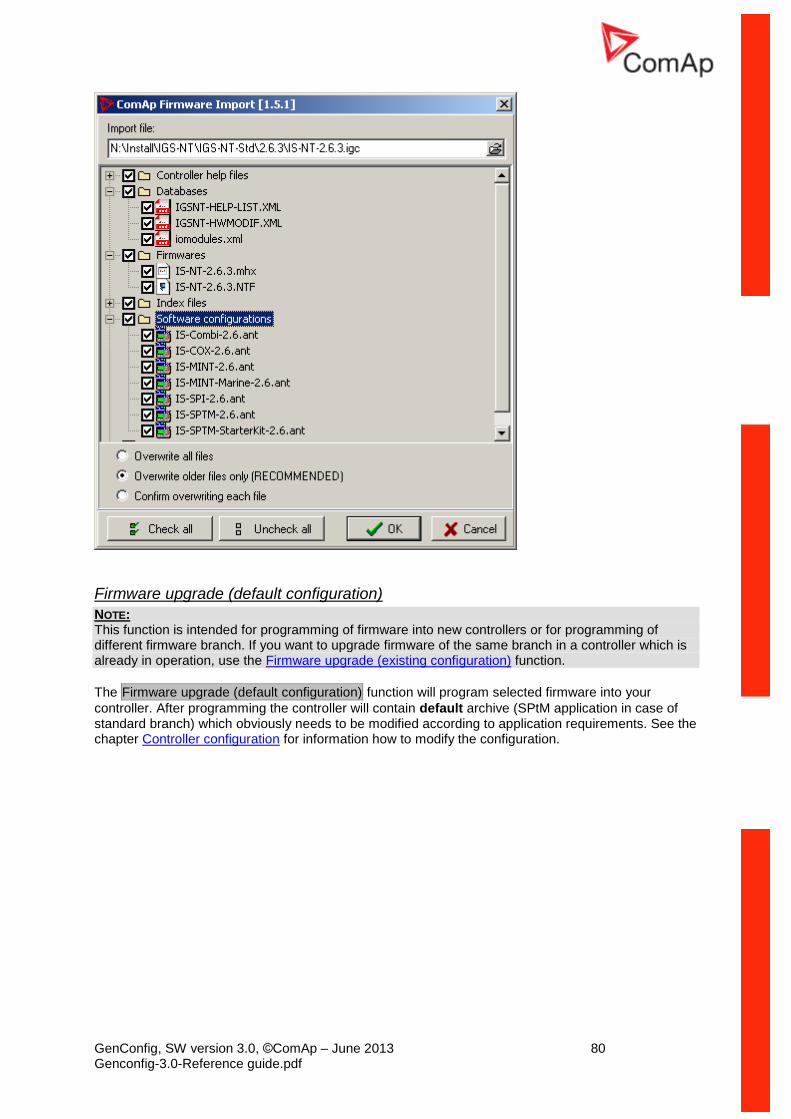
GenConfig, SW version 3.0, ©ComAp – June 2013 80 Genconfig-3.0-Reference guide.pdf
Firmware upgrade (default configuration)
NOTE: This function is intended for programming of firmware into new controllers or for programming of different firmware branch. If you want to upgrade firmware of the same branch in a controller which is already in operation, use the Firmware upgrade (existing configuration) function.
The Firmware upgrade (default configuration) function will program selected firmware into your
controller. After programming the controller will contain default archive (SPtM application in case of standard branch) which obviously needs to be modified according to application requirements. See the chapter Controller configuration for information how to modify the configuration.
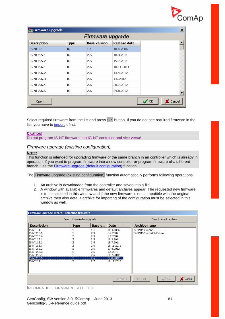
GenConfig, SW version 3.0, ©ComAp – June 2013 81 Genconfig-3.0-Reference guide.pdf
Select required firmware from the list and press OK button. If you do not see required firmware in the
list, you have to import it first.
CAUTION! Do not program IS-NT firmware into IG-NT controller and vice versa!
Firmware upgrade (existing configuration)
NOTE: This function is intended for upgrading firmware of the same branch in an controller which is already in operation. If you want to program firmware into a new controller or program firmware of a different branch, use the Firmware upgrade (default configuration) function.
The Firmware upgrade (existing configuration) function automatically performs following operations:
1. An archive is downloaded from the controller and saved into a file. 2. A window with available firmwares and default archives appear. The requested new firmware
is to be selected in this window and if the new firmware is not compatible with the original archive then also default archive for importing of the configuration must be selected in this window as well.
INCOMPATIBLE FIRMWARE SELECTED
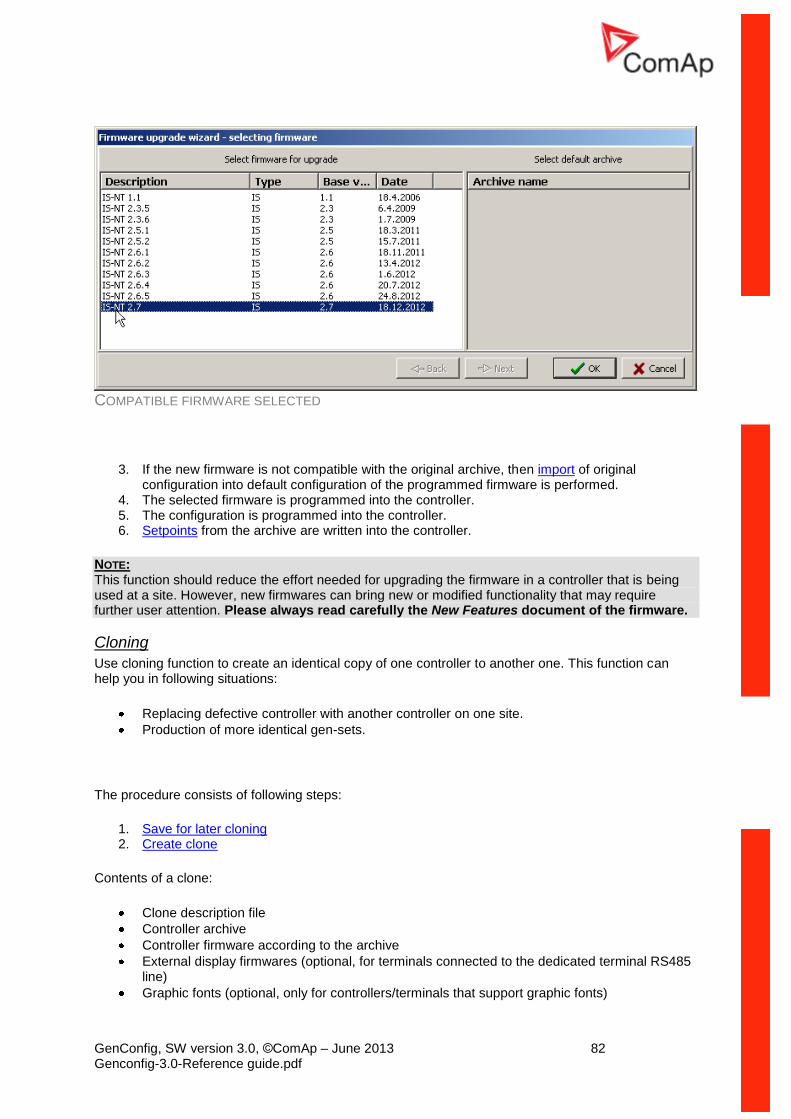
GenConfig, SW version 3.0, ©ComAp – June 2013 82 Genconfig-3.0-Reference guide.pdf
COMPATIBLE FIRMWARE SELECTED
3. If the new firmware is not compatible with the original archive, then import of original configuration into default configuration of the programmed firmware is performed.
4. The selected firmware is programmed into the controller. 5. The configuration is programmed into the controller. 6. Setpoints from the archive are written into the controller.
NOTE: This function should reduce the effort needed for upgrading the firmware in a controller that is being used at a site. However, new firmwares can bring new or modified functionality that may require further user attention. Please always read carefully the New Features document of the firmware.
Cloning
Use cloning function to create an identical copy of one controller to another one. This function can help you in following situations:
Replacing defective controller with another controller on one site.
Production of more identical gen-sets.
The procedure consists of following steps:
1. Save for later cloning 2. Create clone
Contents of a clone:
Clone description file
Controller archive
Controller firmware according to the archive
External display firmwares (optional, for terminals connected to the dedicated terminal RS485 line)
Graphic fonts (optional, only for controllers/terminals that support graphic fonts)
GenConfig, SW version 3.0, ©ComAp – June 2013 83 Genconfig-3.0-Reference guide.pdf
Save for later cloning Save for later cloning (controller only) function will save currently opened configuration including all
changes that were made since opening it from disk or reading from controller. This option does not save firmwares of external terminals and graphic fonts into the clone.
Save for later clonning (controller and displays) function connects automatically to the controller,
reads the configuration from it and saves it into the clone. Firmwares of external terminals connected via the dedicated RS485 bus and graphic fonts are saved into the clone as well.
NOTE: If you get an error message "Firmware XXXX was not found" instead of opening the "Save clone" window, it means you do not have on your disk the firmware, that is present in the controller, so the clone can't be saved. In such a case the proper firmware has to be imported into the GenConfig.
Create clone Use the function Create clone... to make the connected controller identical (firmware, configuration,
setpoints, fonts..) with the original controller from which was the clone saved. The function is intended to be used either for the purpose of complete backup of a site in case the controller or terminal will need to be replaced or for preparing of more identical controllers.
1. Connect the target controller (and displays if needed) to the PC. 2. Start GenConfig and adjust properly connection settings.
3. Go to menu File -> Create clone... and then select required clone.
4. Press OK to program the selected clone into the controller.
Import/Export clone
Press the to export selected saved clone into one file for the purpose of archivation, sending
per e-mail etc. Press the to import previously saved clone into GenConfig.
Programming firmware into a non-responding controller
If the controller does not contain valid firmware a new firmware can't be programmed by standard way. This situation can occur if the connection between PC and the controller was interrupted during previous firmware upgrade. In such a case the controller has blank display and does not communicate with the PC. The boot-jumper must be used to get a valid firmware into the controller.
1. Disconnect power supply from the controller and close the boot-jumper. See the controller manual for details about boot-jumper location.
2. Connect communication cable (appropriate type according to the module used) between the controller and PC.
3. Select direct connection to controller address 1.
4. Go to menu Controller -> Programming and cloning -> Firmware upgrade, select appropriate
firmware and press OK button.
5. Follow instructions given by a message appeared and finally press OK button.
6. Another message will appear when programming is finished. Follow instructions given there.
Display firmware upgrade and font change
Use this menu item to upgrade the firmware or change font in an external IS-Display, IG-Display or InteliVision-5 module which is connected by the RS485 terminal bus.
NOTE:
Use InteliVision FW upgrade for InteliVison-8 firmware upgrade.
NOTE: The IG-NT internal display does not support firmware upgrade.
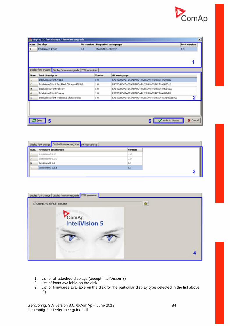
GenConfig, SW version 3.0, ©ComAp – June 2013 84 Genconfig-3.0-Reference guide.pdf
1. List of all attached displays (except InteliVision-8) 2. List of fonts available on the disk 3. List of firmwares available on the disk for the particular display type selected in the list above
(1)
GenConfig, SW version 3.0, ©ComAp – June 2013 85 Genconfig-3.0-Reference guide.pdf
4. Select logo for InteliVision-5 which is displayed during init and wen no connection to controller. Use picture in BMP format with resolution 320x240
5. Pres the Retry button to refresh the list of connected displays e.g. if you just have switched an
external display on.
6. Pres the Write to display button to write selected firmware, font or logo into the selected
display.
NOTE: New display firmwares and fonts may be imported into GenConfig together with new controller firmwares.
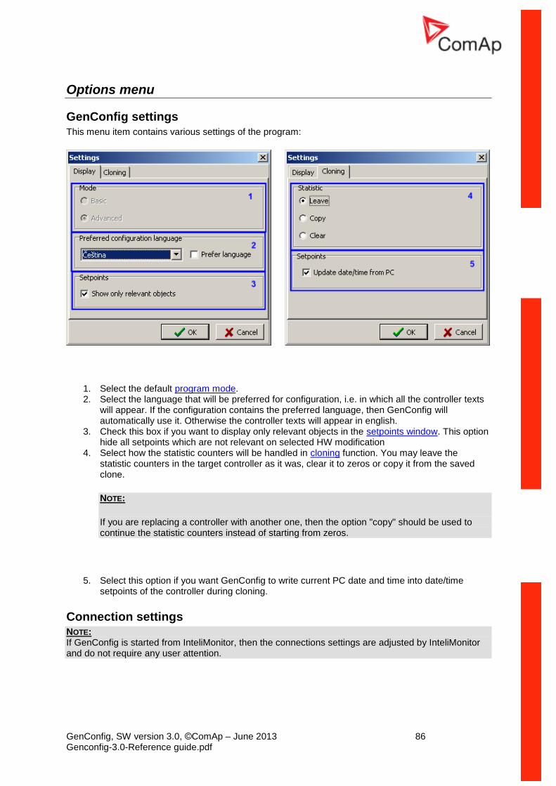
GenConfig, SW version 3.0, ©ComAp – June 2013 86 Genconfig-3.0-Reference guide.pdf
Options menu
GenConfig settings
This menu item contains various settings of the program:
1. Select the default program mode. 2. Select the language that will be preferred for configuration, i.e. in which all the controller texts
will appear. If the configuration contains the preferred language, then GenConfig will automatically use it. Otherwise the controller texts will appear in english.
3. Check this box if you want to display only relevant objects in the setpoints window. This option hide all setpoints which are not relevant on selected HW modification
4. Select how the statistic counters will be handled in cloning function. You may leave the statistic counters in the target controller as it was, clear it to zeros or copy it from the saved clone.
NOTE:
If you are replacing a controller with another one, then the option "copy" should be used to continue the statistic counters instead of starting from zeros.
5. Select this option if you want GenConfig to write current PC date and time into date/time setpoints of the controller during cloning.
Connection settings NOTE: If GenConfig is started from InteliMonitor, then the connections settings are adjusted by InteliMonitor and do not require any user attention.
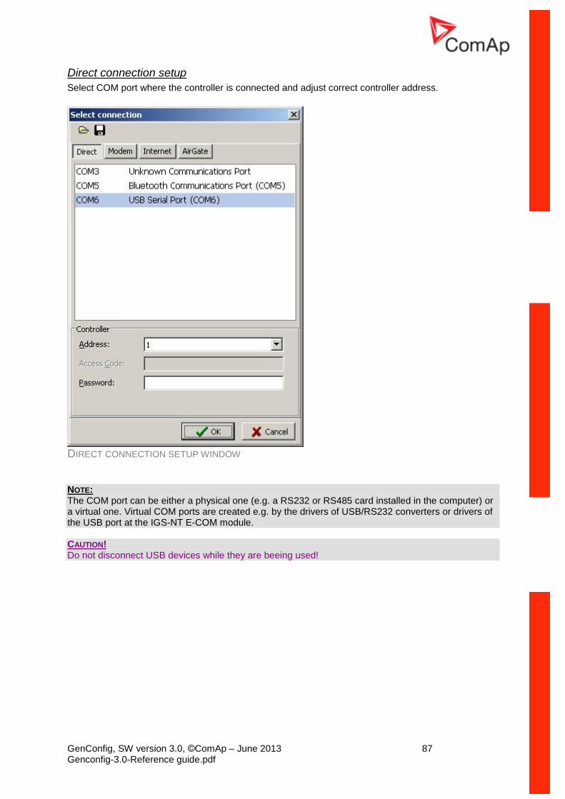
GenConfig, SW version 3.0, ©ComAp – June 2013 87 Genconfig-3.0-Reference guide.pdf
Direct connection setup
Select COM port where the controller is connected and adjust correct controller address.
DIRECT CONNECTION SETUP WINDOW
NOTE: The COM port can be either a physical one (e.g. a RS232 or RS485 card installed in the computer) or a virtual one. Virtual COM ports are created e.g. by the drivers of USB/RS232 converters or drivers of the USB port at the IGS-NT E-COM module. CAUTION! Do not disconnect USB devices while they are beeing used!
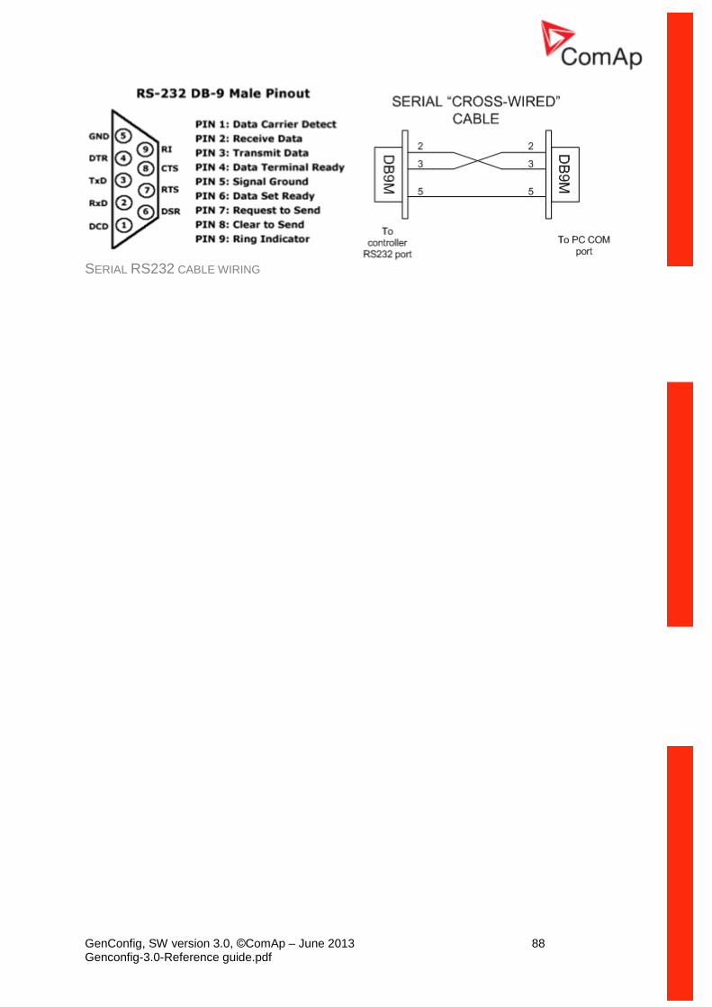
GenConfig, SW version 3.0, ©ComAp – June 2013 88 Genconfig-3.0-Reference guide.pdf
SERIAL RS232 CABLE WIRING
GenConfig, SW version 3.0, ©ComAp – June 2013 89 Genconfig-3.0-Reference guide.pdf
Modem connection setup
1. Select modem that will be used for the connection. The modem must be correctly installed in the computer before using it in GenConfig. Use installation CD provided with the modem to install it into your computer.
NOTE:
Use modem which is compatible with the modem at the controller side. E.g. if there is a GSM modem at the controller, you have to use GSM modem as well.
NOTE:
Please note, that GSM modems provide relative slow connection speed and read or write operations may take tens of minutes.
2. Enter controller phone number. Use format, that is obvious in your local telephone system. 3. Select controller address and enter access code.
MODEM CONNECTION SETUP WINDOW
CAUTION! Firmware programming via modem is not recommended. Connection drop-out will cause the controller to be reprogrammed via cable in bootloader mode.
GenConfig, SW version 3.0, ©ComAp – June 2013 90 Genconfig-3.0-Reference guide.pdf
Ethernet/Internet connection setup
1. Enter IP address of the controller. Enter local IP address if you are connecting from inside of the LAN where the controller (Internet Bridge). If you are connecting from outside of the LAN where the controller is connected, public IP address must be entered. The LAN gateway must forward incoming traffic at port 23 to the local IP of the controller.
2. Select controller address and enter access code.
ETHERNET CONNECTION SETUP WINDOW
GenConfig, SW version 3.0, ©ComAp – June 2013 91 Genconfig-3.0-Reference guide.pdf
AirGate connection setup
1. Enter address of the AirGate server. You may enter the address as domain name or as an IP address. Use the same AirGate server as adjusted in the controller.
NOTE: There is a free public AirGate server at "airgate.comap.cz".
2. Enter the "AirGate ID", which has been assigned by the server to the controller when the controller registered to the server for the first time. The ID remains same, it does not change in time.
3. Select controller address and enter access code.
AIRGATE CONNECTION SETUP WINDOW
Overwrite setpoints option
If this option is checked, the setpoints contained in the archive will be always written into the controller together with the configuration. I.e. the original setpoints present in the controller will be overwritten by the setpoints from the archive.
NOTE: If this option is checked and GenConfig is executed from InteliMonitor, then all changes of setpoints made from InteliMonitor while GenConfig is running will be lost in the moment the configuration is written into the controller!
GenConfig, SW version 3.0, ©ComAp – June 2013 92 Genconfig-3.0-Reference guide.pdf
Clear history option
If this option is checked, then the history data contained in the controller are always cleared after writing the configuration.
Reset from Init
If the controller detects after reset, that the setpoints are not correct (i.e. the checksum does not match), the application is not started and the controller remain in "Init" state to prevent faulty function caused by wrong setpoints. This situation occurs typically after programming of new firmware into the controller.
If this option is checked, GenConfig will reset the controller from "Init" state automatically after programming of firmware or configuration.
Save history to archive Check this menu if you want GenConfig to save always complete archives including history (as in InteliMonitor). This option increases time needed for saving of the archive (as GenConfig must read out the history from the controller before saving..), however it will prevent possible confusing which archives contain history and which don't.
Check consistency before save If this option is checked, then the consistency check is performed automatically before saving the archive. The result of the check is informative only, it does not block saving.
Import firmware See the chapter Firmware upgrade.
Dictionary manager
This menu item is intended for manipulating with dictionaries. Read more about dictionaries and controller languages in the chapter Languages and Translator.
1. Create new custom dictionary 2. Delete selected custom dictionary 3. Rename selected dictionary
GenConfig, SW version 3.0, ©ComAp – June 2013 93 Genconfig-3.0-Reference guide.pdf
4. Export selected dictionary (i.e. save it under specified name to any location) 5. Import a dictionary (i.e. copy a dictionary from any location into the GenConfig dictionary
folder) 6. Show contents (word pairs) of selected dictionary 7. Default dictionary is indicated by gray icon 8. Custom dictionary is indicated by blue icon
ECU List ECU list is a file with ESL extension which contains a list of supported EFI engines and links to their description files (ESF/ESC files). The ECU List is installed with GenConfig and then updated always when a new controller firmware is imported.
Currently used ECU list is also indicated in the "ECU" node of the left tree at the Modules tab.
Always use ECU List - Gensets except if you are using customized controller firmware branch which requires different ecu list.
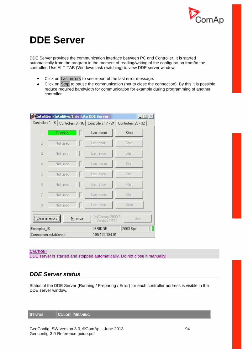
GenConfig, SW version 3.0, ©ComAp – June 2013 94 Genconfig-3.0-Reference guide.pdf
DDE Server
DDE Server provides the communication interface between PC and Controller. It is started automatically from the program in the moment of reading/writing of the configuration from/to the controller. Use ALT-TAB (Windows task switching) to view DDE server window.
Click on Last errors to see report of the last error message.
Click on Stop to pause the communication (not to close the connection). By this it is possible
reduce required bandwidth for communication for example during programming of another controller.
CAUTION! DDE server is started and stopped automatically. Do not close it manually!
DDE Server status
Status of the DDE Server (Running / Preparing / Error) for each controller address is visible in the DDE server window.
STATUS COLOR MEANING
GenConfig, SW version 3.0, ©ComAp – June 2013 95 Genconfig-3.0-Reference guide.pdf
Running green The connection is running, no problems occurred
Programming blue The DDE server is programming firmware or configuration into the controller. Progress in percent is shown in the status text field.
Preparing yellow The DDE server is building-up the connection to the controller. This state may last from seconds up to several minutes depending on connetion type and number of connected controllers.
Error red The connection failed. Use ALT-TAB, select DDE Server and press the "Last errors" button at the controller with appropriate address to see more information
DDE Server error messages
Timeout (continuous)
Connected controller does not answer to DDE server requests. Probable reasons:
The controller is not connected or switched off
The communication cable is wrong
The COM port number is not correctly selected
Setpoints in the controller related to the communication are not correctly adjusted
The communication module in the controller is damaged
Timeout (time to time) Occasional timeouts can be caused by overloading of your operating system
TAPI: requested modem (#) not found
The selected modem is not attached or properly installed
TAPI: unavailable modem Communication port is beeing used by other communication device.
TAPI: Line unexpectedly closed
Modem is configured in Windows, but it is not connected or it is failed.
TAPI: Can't create connection
It is not possible to open connection. Probable reasons:
When "beeping" is audible during start of the connection, the line quality is bad or the other modem is not compatible with the originating one.
When busy tone is audible during start of connection, the destination number is busy or wrong.
When no tone is audible, no phone line is connected to the Modem
Pop-up window with a message Can't open COM
The selected COM port is occupied by other program or is not installed. Check if there is other program using the COM port running or select proper COM port
GenConfig, SW version 3.0, ©ComAp – June 2013 96 Genconfig-3.0-Reference guide.pdf
Appendix
PLC toolbar functions
Export drawing to image
Press the button on the PLC toolbar to export the whole drawing (all sheets) into a windows metafile image (WMF). The WMF is a vector format which can be viewed and edited in most of vector-based graphic editors such as CAD editors, Microsoft Visio etc..
Recovery the drawing The program creates backups of your drawing automatically. If you close the drawing accidentally, you
can recovery it back from the backup copies. Press the button on the PLC toolbar to select which backup copy you want to open. The filenames of the backup copies are generated automatically from current date and time according to following scheme: "yyyy_mm_dd_hh_mm_ss_xxxx.xml"
CAUTION! If you open a backup copy which was saved from an archive of different firmware version and/or branch than the current archive is, the configuration of sheet inputs and outputs may be incorrect!!
Print the drawing
Click to the icon to print the whole drawing. After clicking the print preview window is opened,
where you can see how the drawing will appear on the paper. Then click to Print button to open the
standard windows print dialog.
NOTE: Each sheet is printed on two separate sheets of paper. The first paper contains the sheet graphic and the second paper (or more) contains summary of the sheet contents in the form of a table. The graphic is always zoomed to fit one paper.
Cut selection
Use the button or CTRL+X to cut the current selection from the sheet into the clipboard.
Copy selection
Use the button or CTRL+C to copy the current selection from the sheet into the clipboard.
Paste from clipboard
Use the button or CTRL+V to paste the contents of the clipboard into the active sheet.
NOTE: The clipboard is cleared after the it is pasted into the sheet.
GenConfig, SW version 3.0, ©ComAp – June 2013 97 Genconfig-3.0-Reference guide.pdf
Select whole sheet contents
Press the button to select all contents of the active sheet.
Cancel selection
Press the button to cancel the current selection.
Delete selection
Press the button to delete current selection.
Delete whole sheet contents
Press the button to delete the whole contents of the active sheet.
Reroute selected wire(s)
Undo last change
Press the button or CTRL+Z to undo the last change that was made in the drawing.
Redo last undo change
Press the button to cancel the last undo step and return one step back.
Show drawing history
Press the button to show/hide a panel at the right of the PLC editor window, which contains an overview of last changes that were made in the drawing.
Repaint drawing
If the drawing is not correctly displayed, press the button to repaint it.
Show hints
Press the button to activate/deactivate hints for the blocks placed in the drawing. If the hints are enabled and the mouse pointer is located over a block, a hint with block configuration summary is displayed.
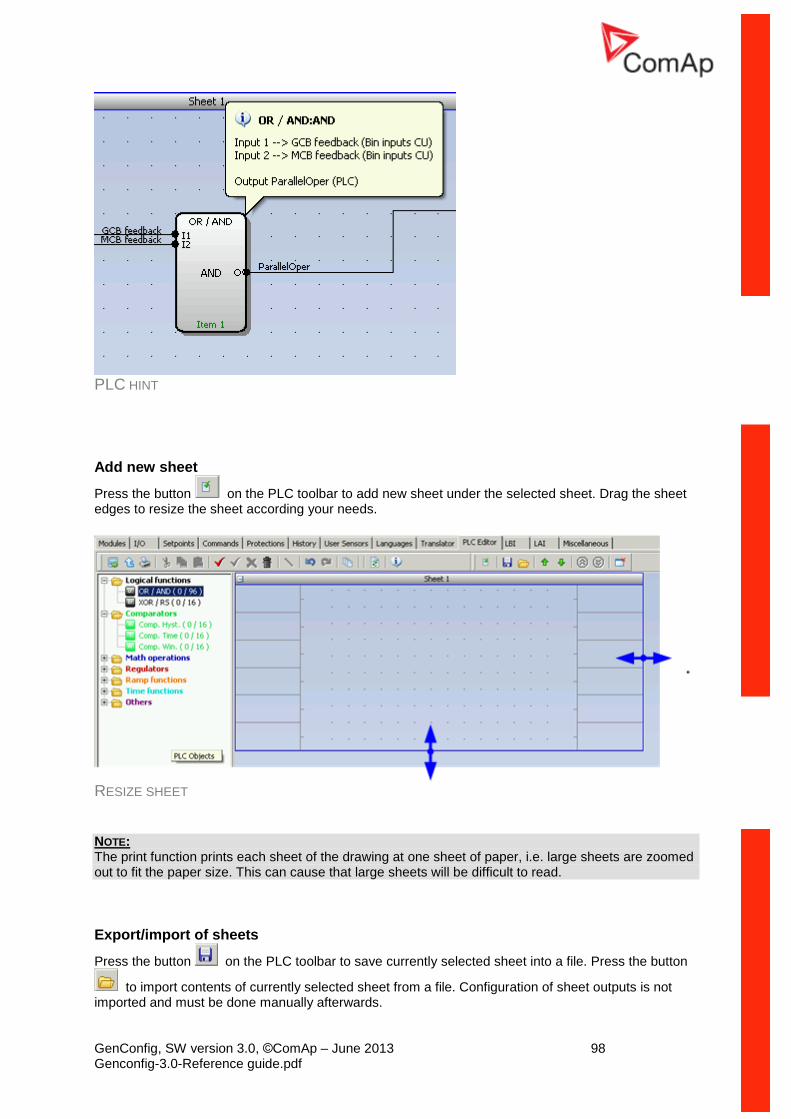
GenConfig, SW version 3.0, ©ComAp – June 2013 98 Genconfig-3.0-Reference guide.pdf
PLC HINT
Add new sheet
Press the button on the PLC toolbar to add new sheet under the selected sheet. Drag the sheet edges to resize the sheet according your needs.
RESIZE SHEET
NOTE: The print function prints each sheet of the drawing at one sheet of paper, i.e. large sheets are zoomed out to fit the paper size. This can cause that large sheets will be difficult to read.
Export/import of sheets
Press the button on the PLC toolbar to save currently selected sheet into a file. Press the button
to import contents of currently selected sheet from a file. Configuration of sheet outputs is not imported and must be done manually afterwards.
GenConfig, SW version 3.0, ©ComAp – June 2013 99 Genconfig-3.0-Reference guide.pdf
NOTE: The import will overwrite all previous sheet contents! CAUTION! Please always check configuration of sheet inputs, especially if you import a sheet which was originally created in different firmware branch and/or version. EXAMPLE: This function can be used e.g. if you have a sheet containing one particular function and you want to use this functionality repeatedly.
Export/import of sheets
Press the button on the PLC toolbar to save currently selected sheet into a file. Press the button
to import contents of currently selected sheet from a file. Configuration of sheet outputs is not imported and must be done manually afterwards.
NOTE: The import will overwrite all previous sheet contents! CAUTION! Please always check configuration of sheet inputs, especially if you import a sheet which was originally created in different firmware branch and/or version. EXAMPLE: This function can be used e.g. if you have a sheet containing one particular function and you want to use this functionality repeatedly.
Move a sheet
Press the button or on the PLC toolbar to move the currently selected sheet within the drawing up or down.
CAUTION! Moving sheets causes the order of evaluation of the blocks will be different and might cause the PLC program to work incorrectly. CAUTION! Moving sheets may cause the targets of "jump" blocks will be invalid. Please check "jump" blocks after moving a sheet.
GenConfig, SW version 3.0, ©ComAp – June 2013 100 Genconfig-3.0-Reference guide.pdf
Go to next/previous sheet
Press the button or on the PLC toolbar to display and activate next or previous sheet.
NOTE: The active sheet is indicated by the blue sheet border.
Go to next/previous sheet
Press the button or on the PLC toolbar to display and activate next or previous sheet.
NOTE: The active sheet is indicated by the blue sheet border.
Delete a sheet
Press the button on the PLC toolbar to delete currently selected sheet from the drawing.
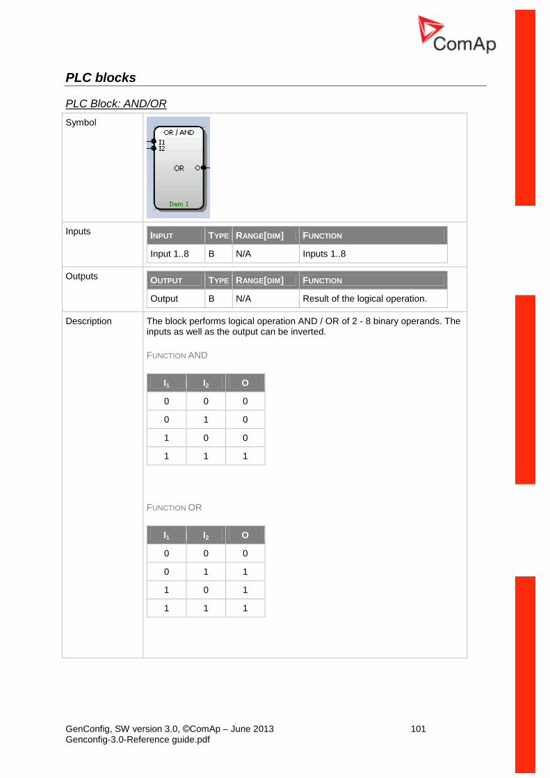
GenConfig, SW version 3.0, ©ComAp – June 2013 101 Genconfig-3.0-Reference guide.pdf
PLC blocks
PLC Block: AND/OR
Symbol
Inputs INPUT TYPE RANGE[DIM] FUNCTION
Input 1..8 B N/A Inputs 1..8
Outputs OUTPUT TYPE RANGE[DIM] FUNCTION
Output B N/A Result of the logical operation.
Description The block performs logical operation AND / OR of 2 - 8 binary operands. The inputs as well as the output can be inverted.
FUNCTION AND
I1 I2 O
0 0 0
0 1 0
1 0 0
1 1 1
FUNCTION OR
I1 I2 O
0 0 0
0 1 1
1 0 1
1 1 1
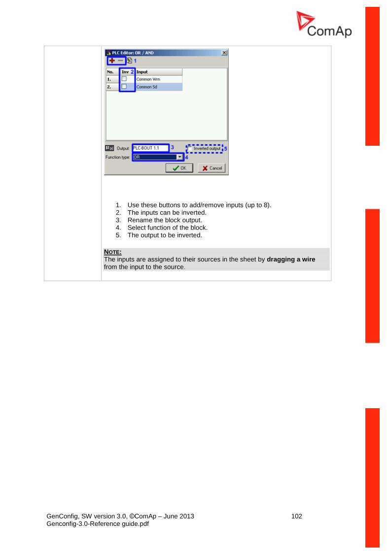
GenConfig, SW version 3.0, ©ComAp – June 2013 102 Genconfig-3.0-Reference guide.pdf
1. Use these buttons to add/remove inputs (up to 8). 2. The inputs can be inverted. 3. Rename the block output. 4. Select function of the block. 5. The output to be inverted.
NOTE: The inputs are assigned to their sources in the sheet by dragging a wire from the input to the source.
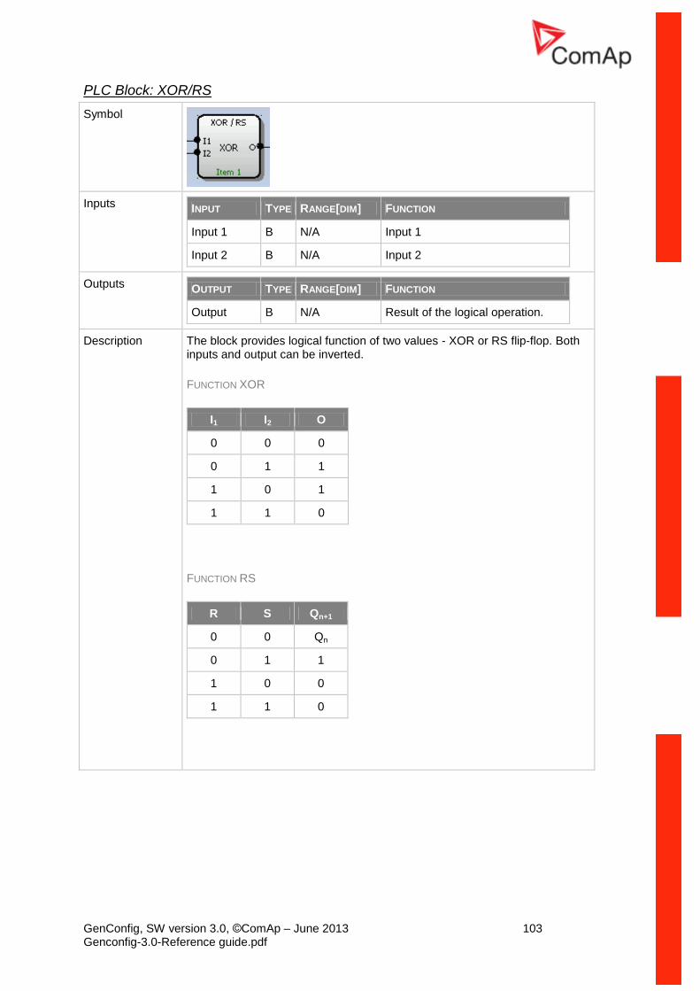
GenConfig, SW version 3.0, ©ComAp – June 2013 103 Genconfig-3.0-Reference guide.pdf
PLC Block: XOR/RS
Symbol
Inputs INPUT TYPE RANGE[DIM] FUNCTION
Input 1 B N/A Input 1
Input 2 B N/A Input 2
Outputs OUTPUT TYPE RANGE[DIM] FUNCTION
Output B N/A Result of the logical operation.
Description The block provides logical function of two values - XOR or RS flip-flop. Both inputs and output can be inverted.
FUNCTION XOR
I1 I2 O
0 0 0
0 1 1
1 0 1
1 1 0
FUNCTION RS
R S Qn+1
0 0 Qn
0 1 1
1 0 0
1 1 0
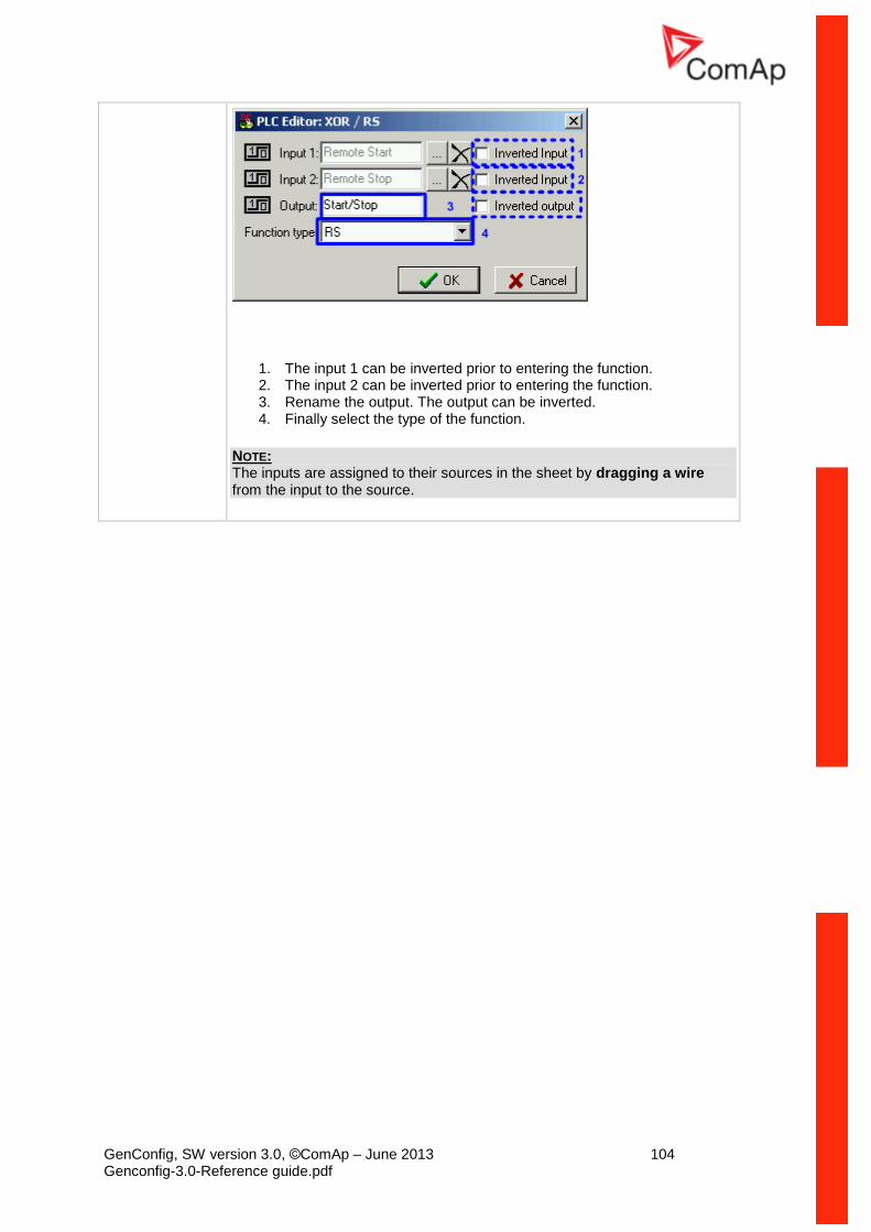
GenConfig, SW version 3.0, ©ComAp – June 2013 104 Genconfig-3.0-Reference guide.pdf
1. The input 1 can be inverted prior to entering the function. 2. The input 2 can be inverted prior to entering the function. 3. Rename the output. The output can be inverted. 4. Finally select the type of the function.
NOTE: The inputs are assigned to their sources in the sheet by dragging a wire from the input to the source.
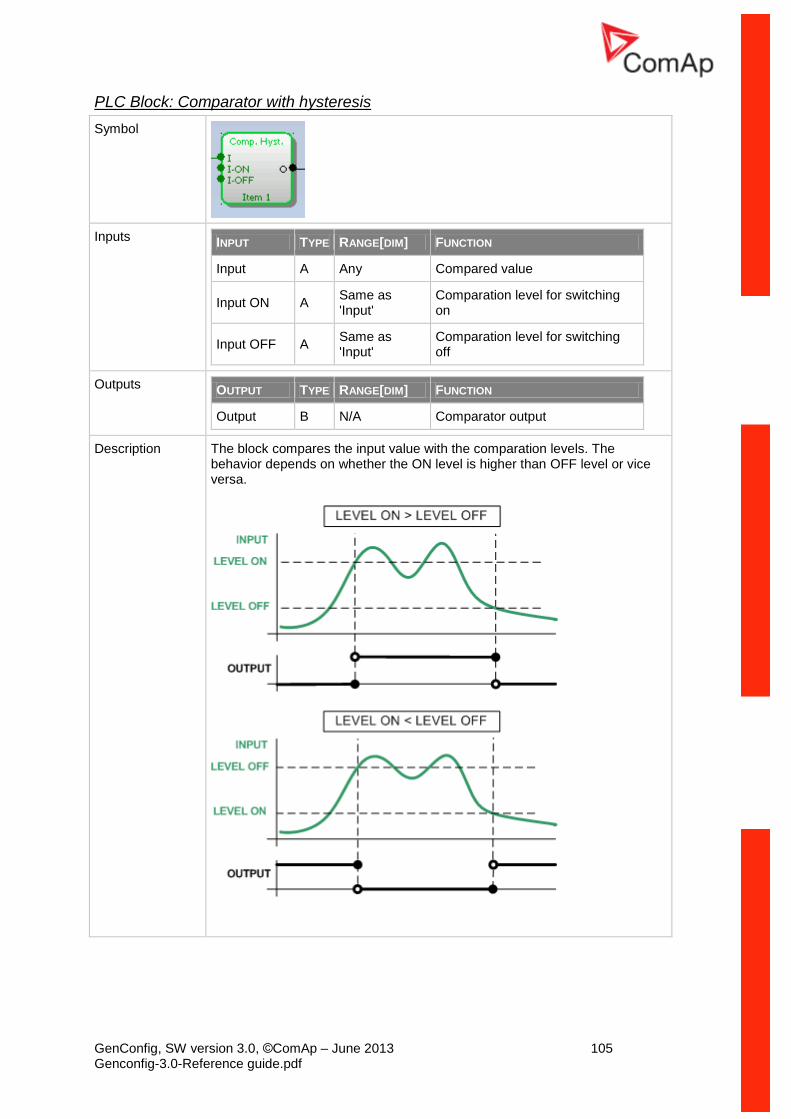
GenConfig, SW version 3.0, ©ComAp – June 2013 105 Genconfig-3.0-Reference guide.pdf
PLC Block: Comparator with hysteresis
Symbol
Inputs INPUT TYPE RANGE[DIM] FUNCTION
Input A Any Compared value
Input ON A Same as 'Input'
Comparation level for switching on
Input OFF A Same as 'Input'
Comparation level for switching off
Outputs OUTPUT TYPE RANGE[DIM] FUNCTION
Output B N/A Comparator output
Description The block compares the input value with the comparation levels. The behavior depends on whether the ON level is higher than OFF level or vice versa.
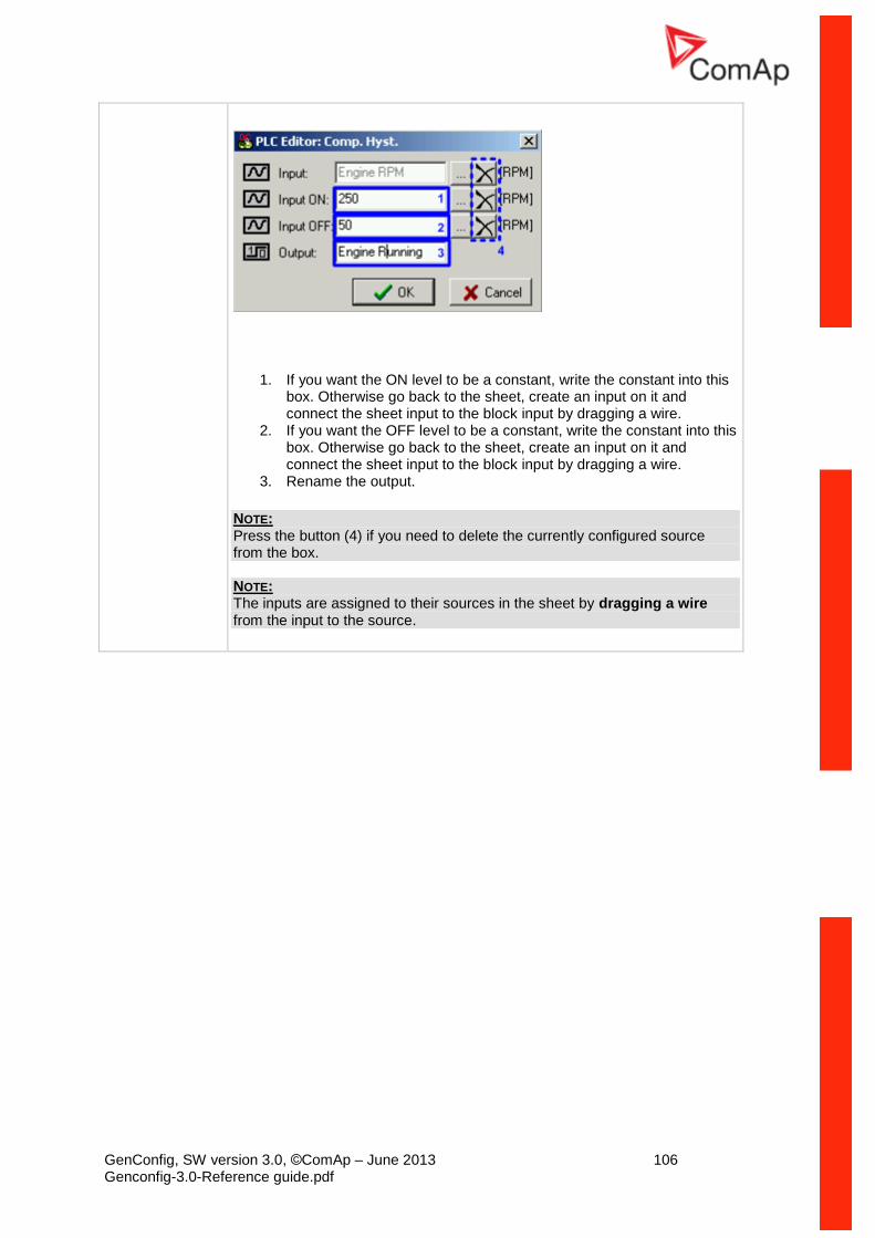
GenConfig, SW version 3.0, ©ComAp – June 2013 106 Genconfig-3.0-Reference guide.pdf
1. If you want the ON level to be a constant, write the constant into this box. Otherwise go back to the sheet, create an input on it and connect the sheet input to the block input by dragging a wire.
2. If you want the OFF level to be a constant, write the constant into this box. Otherwise go back to the sheet, create an input on it and connect the sheet input to the block input by dragging a wire.
3. Rename the output.
NOTE: Press the button (4) if you need to delete the currently configured source from the box. NOTE: The inputs are assigned to their sources in the sheet by dragging a wire from the input to the source.
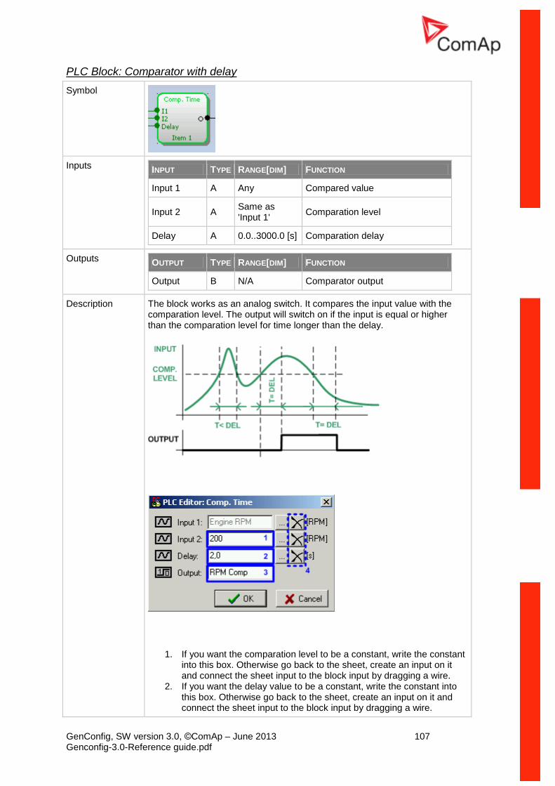
GenConfig, SW version 3.0, ©ComAp – June 2013 107 Genconfig-3.0-Reference guide.pdf
PLC Block: Comparator with delay
Symbol
Inputs INPUT TYPE RANGE[DIM] FUNCTION
Input 1 A Any Compared value
Input 2 A Same as 'Input 1'
Comparation level
Delay A 0.0..3000.0 [s] Comparation delay
Outputs OUTPUT TYPE RANGE[DIM] FUNCTION
Output B N/A Comparator output
Description The block works as an analog switch. It compares the input value with the comparation level. The output will switch on if the input is equal or higher than the comparation level for time longer than the delay.
1. If you want the comparation level to be a constant, write the constant into this box. Otherwise go back to the sheet, create an input on it and connect the sheet input to the block input by dragging a wire.
2. If you want the delay value to be a constant, write the constant into this box. Otherwise go back to the sheet, create an input on it and connect the sheet input to the block input by dragging a wire.

GenConfig, SW version 3.0, ©ComAp – June 2013 108 Genconfig-3.0-Reference guide.pdf
3. Rename the output.
NOTE: Press the button (4) if you need to delete the currently configured source from the box. NOTE: The inputs are assigned to their sources in the sheet by dragging a wire from the input to the source.
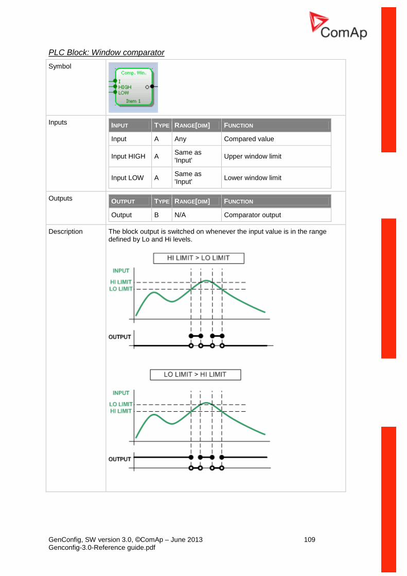
GenConfig, SW version 3.0, ©ComAp – June 2013 109 Genconfig-3.0-Reference guide.pdf
PLC Block: Window comparator
Symbol
Inputs INPUT TYPE RANGE[DIM] FUNCTION
Input A Any Compared value
Input HIGH A Same as 'Input'
Upper window limit
Input LOW A Same as 'Input'
Lower window limit
Outputs OUTPUT TYPE RANGE[DIM] FUNCTION
Output B N/A Comparator output
Description The block output is switched on whenever the input value is in the range defined by Lo and Hi levels.

GenConfig, SW version 3.0, ©ComAp – June 2013 110 Genconfig-3.0-Reference guide.pdf
1. If you want the Hi level to be a constant, write the constant into this box. Otherwise go back to the sheet, create an input on it and connect the sheet input to the block input by dragging a wire.
2. If you want the Lo level to be a constant, write the constant into this box. Otherwise go back to the sheet, create an input on it and connect the sheet input to the block input by dragging a wire.
3. Rename the output.
NOTE: Press the button (4) if you need to delete the currently configured source from the box. NOTE: The inputs are assigned to their sources in the sheet by dragging a wire from the input to the source.
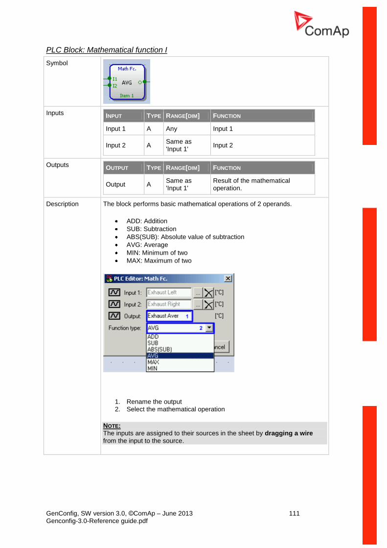
GenConfig, SW version 3.0, ©ComAp – June 2013 111 Genconfig-3.0-Reference guide.pdf
PLC Block: Mathematical function I
Symbol
Inputs INPUT TYPE RANGE[DIM] FUNCTION
Input 1 A Any Input 1
Input 2 A Same as 'Input 1'
Input 2
Outputs OUTPUT TYPE RANGE[DIM] FUNCTION
Output A Same as 'Input 1'
Result of the mathematical operation.
Description The block performs basic mathematical operations of 2 operands.
ADD: Addition
SUB: Subtraction
ABS(SUB): Absolute value of subtraction
AVG: Average
MIN: Minimum of two
MAX: Maximum of two
1. Rename the output 2. Select the mathematical operation
NOTE: The inputs are assigned to their sources in the sheet by dragging a wire from the input to the source.
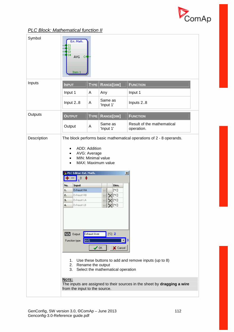
GenConfig, SW version 3.0, ©ComAp – June 2013 112 Genconfig-3.0-Reference guide.pdf
PLC Block: Mathematical function II
Symbol
Inputs INPUT TYPE RANGE[DIM] FUNCTION
Input 1 A Any Input 1
Input 2..8 A Same as 'Input 1'
Inputs 2..8
Outputs OUTPUT TYPE RANGE[DIM] FUNCTION
Output A Same as 'Input 1'
Result of the mathematical operation.
Description The block performs basic mathematical operations of 2 - 8 operands.
ADD: Addition
AVG: Average
MIN: Minimal value
MAX: Maximum value
1. Use these buttons to add and remove inputs (up to 8) 2. Rename the output 3. Select the mathematical operation
NOTE: The inputs are assigned to their sources in the sheet by dragging a wire from the input to the source.
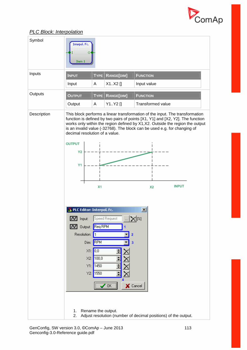
GenConfig, SW version 3.0, ©ComAp – June 2013 113 Genconfig-3.0-Reference guide.pdf
PLC Block: Interpolation
Symbol
Inputs INPUT TYPE RANGE[DIM] FUNCTION
Input A X1..X2 [] Input value
Outputs OUTPUT TYPE RANGE[DIM] FUNCTION
Output A Y1..Y2 [] Transformed value
Description This block performs a linear transformation of the input. The transformation function is defined by two pairs of points [X1, Y1] and [X2, Y2]. The function works only within the region defined by X1,X2. Outside the region the output is an invalid value (-32768). The block can be used e.g. for changing of decimal resolution of a value.
1. Rename the output. 2. Adjust resolution (number of decimal positions) of the output.
GenConfig, SW version 3.0, ©ComAp – June 2013 114 Genconfig-3.0-Reference guide.pdf
3. Adjust dimension of the output. 4. Enter the points of the transformation function. The value of X1 must
be lower than the value of X2, however Y1 needn't to be lower than Y2, i.e. the characteristic can be also negative.
NOTE: The inputs are assigned to their sources in the sheet by dragging a wire from the input to the source.
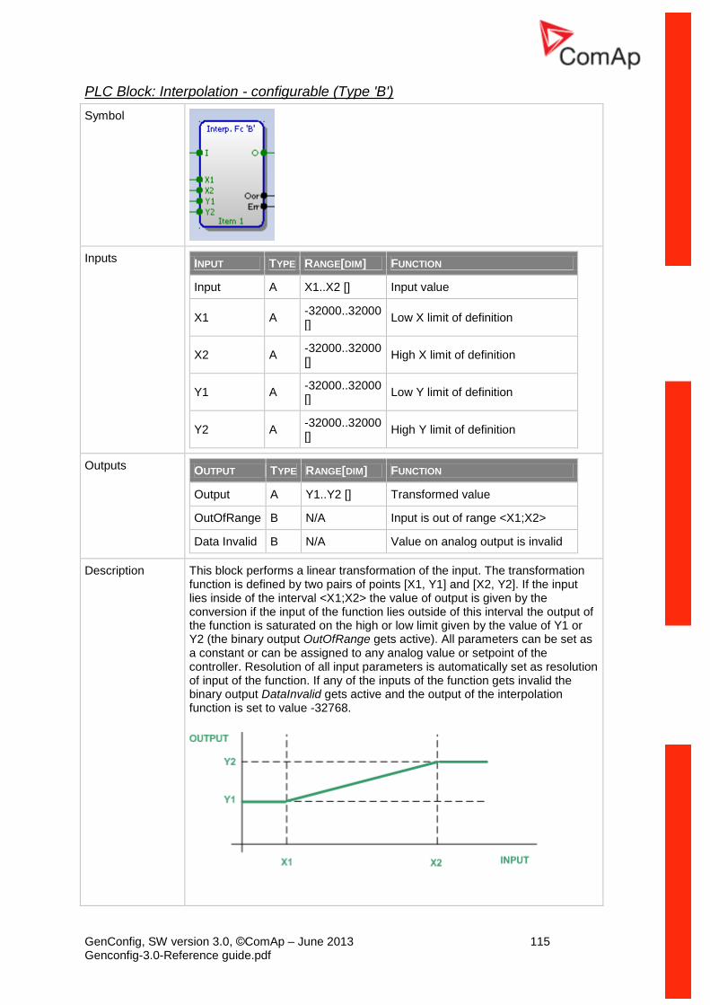
GenConfig, SW version 3.0, ©ComAp – June 2013 115 Genconfig-3.0-Reference guide.pdf
PLC Block: Interpolation - configurable (Type 'B')
Symbol
Inputs INPUT TYPE RANGE[DIM] FUNCTION
Input A X1..X2 [] Input value
X1 A -32000..32000 []
Low X limit of definition
X2 A -32000..32000 []
High X limit of definition
Y1 A -32000..32000 []
Low Y limit of definition
Y2 A -32000..32000 []
High Y limit of definition
Outputs OUTPUT TYPE RANGE[DIM] FUNCTION
Output A Y1..Y2 [] Transformed value
OutOfRange B N/A Input is out of range <X1;X2>
Data Invalid B N/A Value on analog output is invalid
Description This block performs a linear transformation of the input. The transformation function is defined by two pairs of points [X1, Y1] and [X2, Y2]. If the input lies inside of the interval <X1;X2> the value of output is given by the conversion if the input of the function lies outside of this interval the output of the function is saturated on the high or low limit given by the value of Y1 or Y2 (the binary output OutOfRange gets active). All parameters can be set as a constant or can be assigned to any analog value or setpoint of the controller. Resolution of all input parameters is automatically set as resolution of input of the function. If any of the inputs of the function gets invalid the binary output DataInvalid gets active and the output of the interpolation function is set to value -32768.
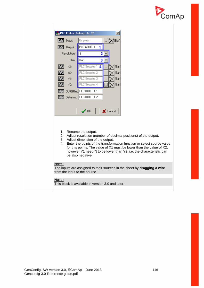
GenConfig, SW version 3.0, ©ComAp – June 2013 116 Genconfig-3.0-Reference guide.pdf
1. Rename the output. 2. Adjust resolution (number of decimal positions) of the output. 3. Adjust dimension of the output. 4. Enter the points of the transformation function or select source value
for this points. The value of X1 must be lower than the value of X2, however Y1 needn't to be lower than Y2, i.e. the characteristic can be also negative.
NOTE: The inputs are assigned to their sources in the sheet by dragging a wire from the input to the source. NOTE: This block is available in version 3.0 and later.
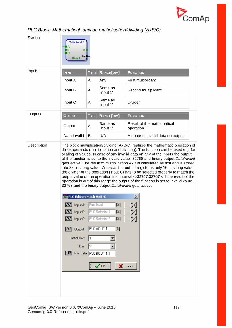
GenConfig, SW version 3.0, ©ComAp – June 2013 117 Genconfig-3.0-Reference guide.pdf
PLC Block: Mathematical function multiplication/dividing (AxB/C)
Symbol
Inputs INPUT TYPE RANGE[DIM] FUNCTION
Input A A Any First multiplicant
Input B A Same as 'Input 1'
Second multiplicant
Input C A Same as 'Input 1'
Divider
Outputs OUTPUT TYPE RANGE[DIM] FUNCTION
Output A Same as 'Input 1'
Result of the mathematical operation.
Data Invalid B N/A Atribute of invalid data on output
Description The block multiplication/dividing (AxB/C) realizes the mathematic operation of three operands (multiplication and dividing). The function can be used e.g. for scaling of values. In case of any invalid data on any of the inputs the output of the function is set to the invalid value -32768 and binary output DataInvalid gets active. The result of multiplication AxB is calculated as first and is stored into 32 bits long value. Whereas the output register is only 16 bits long value, the divider of the operation (input C) has to be selected properly to match the output value of the operation into interval <-32767;32767>. If the result of the operation is out of this range the output of the function is set to invalid value -32768 and the binary output DataInvalid gets active.
GenConfig, SW version 3.0, ©ComAp – June 2013 118 Genconfig-3.0-Reference guide.pdf
NOTE: The inputs are assigned to their sources in the sheet by dragging a wire from the input to the source. NOTE: This block is available in version 3.0 and later.
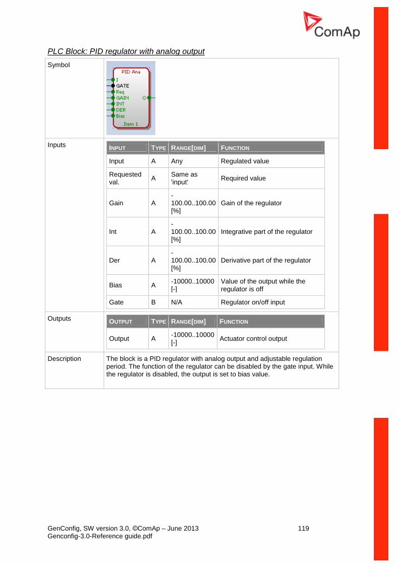
GenConfig, SW version 3.0, ©ComAp – June 2013 119 Genconfig-3.0-Reference guide.pdf
PLC Block: PID regulator with analog output
Symbol
Inputs INPUT TYPE RANGE[DIM] FUNCTION
Input A Any Regulated value
Requested val.
A Same as 'input'
Required value
Gain A -100.00..100.00 [%]
Gain of the regulator
Int A -100.00..100.00 [%]
Integrative part of the regulator
Der A -100.00..100.00 [%]
Derivative part of the regulator
Bias A -10000..10000 [-]
Value of the output while the regulator is off
Gate B N/A Regulator on/off input
Outputs OUTPUT TYPE RANGE[DIM] FUNCTION
Output A -10000..10000 [-]
Actuator control output
Description The block is a PID regulator with analog output and adjustable regulation period. The function of the regulator can be disabled by the gate input. While the regulator is disabled, the output is set to bias value.
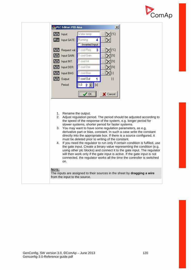
GenConfig, SW version 3.0, ©ComAp – June 2013 120 Genconfig-3.0-Reference guide.pdf
1. Rename the output. 2. Adjust regulation period. The period should be adjusted according to
the speed of the response of the system, e.g. longer period for slower systems, shorter period for faster systems.
3. You may want to have some regulation parameters, as e.g. derivative part or bias, constant. In such a case write the constant directly into the appropriate box. If there is a source configured, it must be deleted prior to writing of the constant.
4. If you need the regulator to run only if certain condition is fulfiled, use the gate input. Create a binary value representing the condition (e.g. using other plc blocks) and connect it to the gate input. The regulator will then work only if the gate input is active. If the gate input is not connected, the regulator works all the time the controller is switched on.
NOTE: The inputs are assigned to their sources in the sheet by dragging a wire from the input to the source.
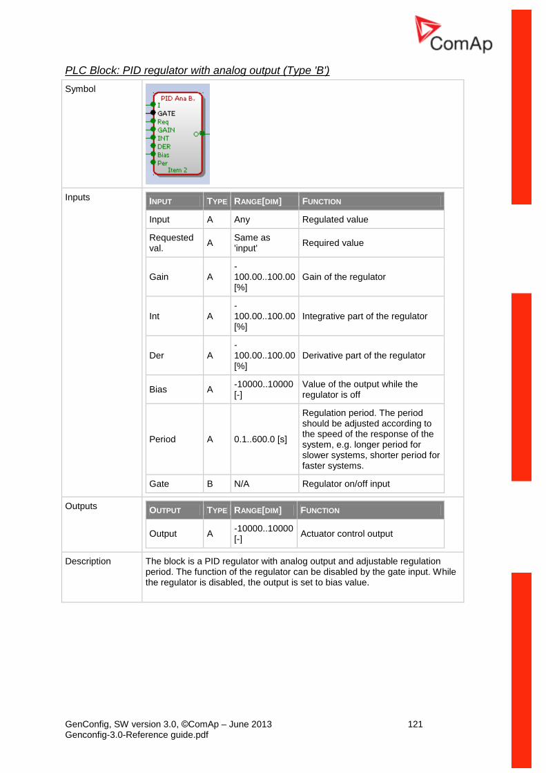
GenConfig, SW version 3.0, ©ComAp – June 2013 121 Genconfig-3.0-Reference guide.pdf
PLC Block: PID regulator with analog output (Type 'B')
Symbol
Inputs INPUT TYPE RANGE[DIM] FUNCTION
Input A Any Regulated value
Requested val.
A Same as 'input'
Required value
Gain A -100.00..100.00 [%]
Gain of the regulator
Int A -100.00..100.00 [%]
Integrative part of the regulator
Der A -100.00..100.00 [%]
Derivative part of the regulator
Bias A -10000..10000 [-]
Value of the output while the regulator is off
Period A 0.1..600.0 [s]
Regulation period. The period should be adjusted according to the speed of the response of the system, e.g. longer period for slower systems, shorter period for faster systems.
Gate B N/A Regulator on/off input
Outputs OUTPUT TYPE RANGE[DIM] FUNCTION
Output A -10000..10000 [-]
Actuator control output
Description The block is a PID regulator with analog output and adjustable regulation period. The function of the regulator can be disabled by the gate input. While the regulator is disabled, the output is set to bias value.
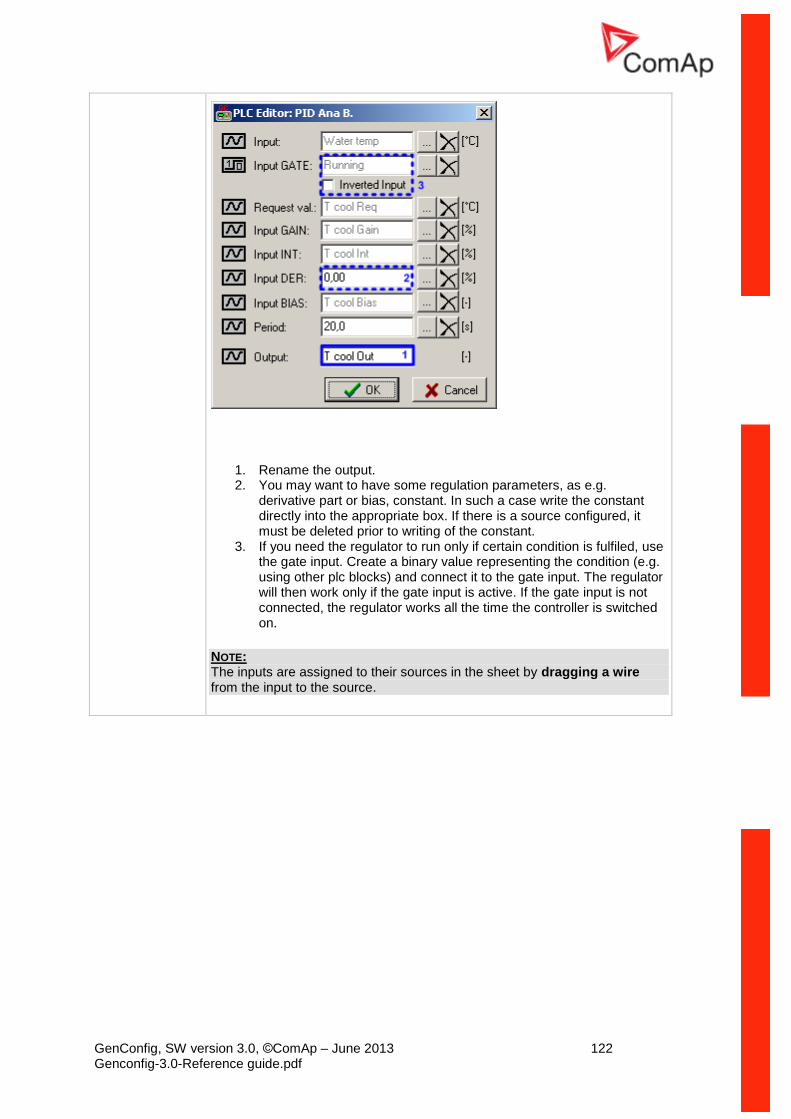
GenConfig, SW version 3.0, ©ComAp – June 2013 122 Genconfig-3.0-Reference guide.pdf
1. Rename the output. 2. You may want to have some regulation parameters, as e.g.
derivative part or bias, constant. In such a case write the constant directly into the appropriate box. If there is a source configured, it must be deleted prior to writing of the constant.
3. If you need the regulator to run only if certain condition is fulfiled, use the gate input. Create a binary value representing the condition (e.g. using other plc blocks) and connect it to the gate input. The regulator will then work only if the gate input is active. If the gate input is not connected, the regulator works all the time the controller is switched on.
NOTE: The inputs are assigned to their sources in the sheet by dragging a wire from the input to the source.
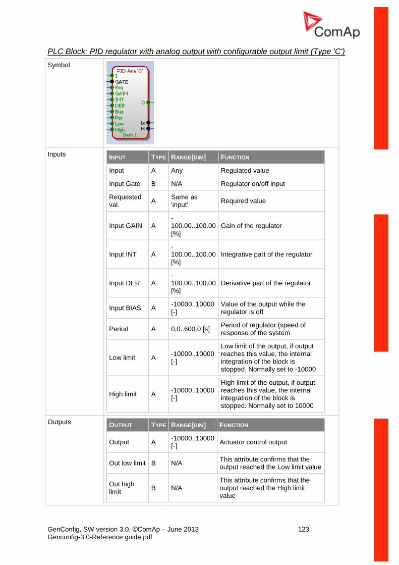
GenConfig, SW version 3.0, ©ComAp – June 2013 123 Genconfig-3.0-Reference guide.pdf
PLC Block: PID regulator with analog output with configurable output limit (Type 'C')
Symbol
Inputs INPUT TYPE RANGE[DIM] FUNCTION
Input A Any Regulated value
Input Gate B N/A Regulator on/off input
Requested val.
A Same as 'input'
Required value
Input GAIN A -100.00..100.00 [%]
Gain of the regulator
Input INT A -100.00..100.00 [%]
Integrative part of the regulator
Input DER A -100.00..100.00 [%]
Derivative part of the regulator
Input BIAS A -10000..10000 [-]
Value of the output while the regulator is off
Period A 0,0..600,0 [s] Period of regulator (speed of response of the system
Low limit A -10000..10000 [-]
Low limit of the output, if output reaches this value, the internal integration of the block is stopped. Normally set to -10000
High limit A -10000..10000 [-]
High limit of the output, if output reaches this value, the internal integration of the block is stopped. Normally set to 10000
Outputs OUTPUT TYPE RANGE[DIM] FUNCTION
Output A -10000..10000 [-]
Actuator control output
Out low limit B N/A This attribute confirms that the output reached the Low limit value
Out high limit
B N/A This attribute confirms that the output reached the High limit value
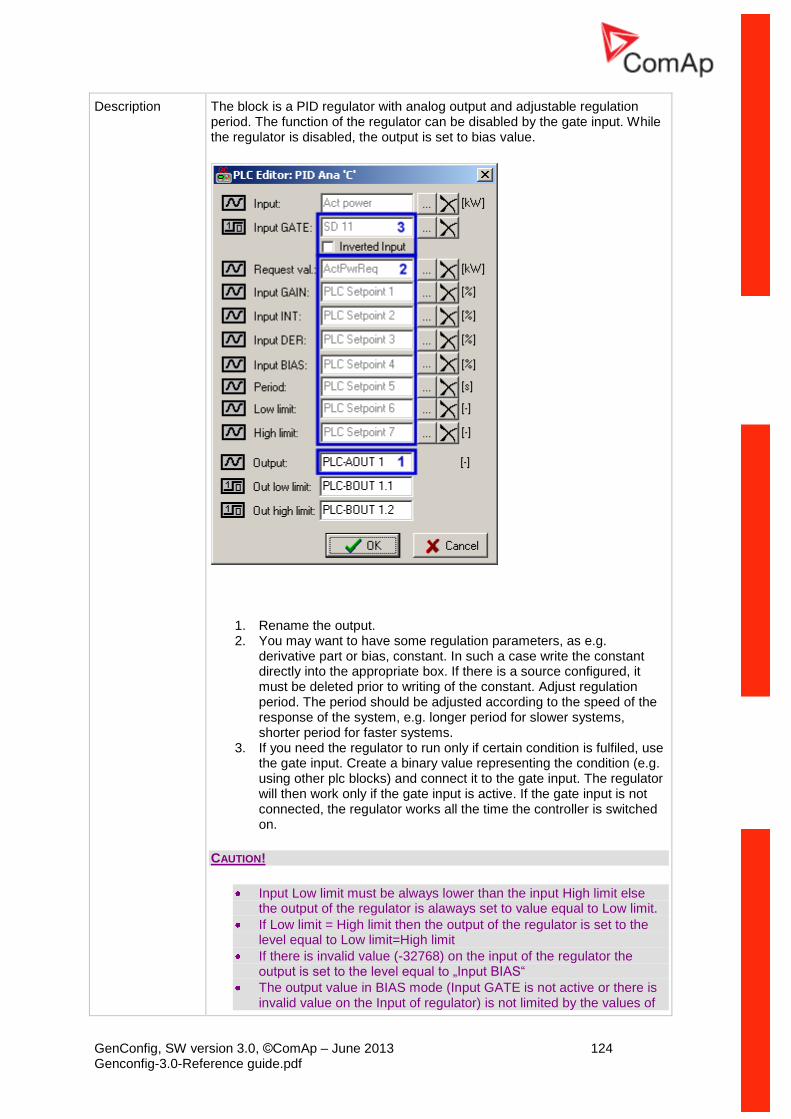
GenConfig, SW version 3.0, ©ComAp – June 2013 124 Genconfig-3.0-Reference guide.pdf
Description The block is a PID regulator with analog output and adjustable regulation period. The function of the regulator can be disabled by the gate input. While the regulator is disabled, the output is set to bias value.
1. Rename the output. 2. You may want to have some regulation parameters, as e.g.
derivative part or bias, constant. In such a case write the constant directly into the appropriate box. If there is a source configured, it must be deleted prior to writing of the constant. Adjust regulation period. The period should be adjusted according to the speed of the response of the system, e.g. longer period for slower systems, shorter period for faster systems.
3. If you need the regulator to run only if certain condition is fulfiled, use the gate input. Create a binary value representing the condition (e.g. using other plc blocks) and connect it to the gate input. The regulator will then work only if the gate input is active. If the gate input is not connected, the regulator works all the time the controller is switched on.
CAUTION!
Input Low limit must be always lower than the input High limit else the output of the regulator is alaways set to value equal to Low limit.
If Low limit = High limit then the output of the regulator is set to the level equal to Low limit=High limit
If there is invalid value (-32768) on the input of the regulator the output is set to the level equal to „Input BIAS“
The output value in BIAS mode (Input GATE is not active or there is invalid value on the Input of regulator) is not limited by the values of
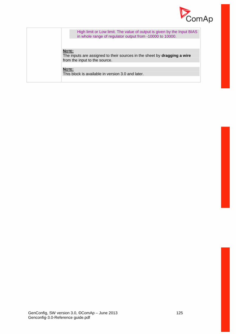
GenConfig, SW version 3.0, ©ComAp – June 2013 125 Genconfig-3.0-Reference guide.pdf
High limit or Low limit. The value of output is given by the Input BIAS in whole range of regulator output from -10000 to 10000.
NOTE: The inputs are assigned to their sources in the sheet by dragging a wire from the input to the source. NOTE: This block is available in version 3.0 and later.
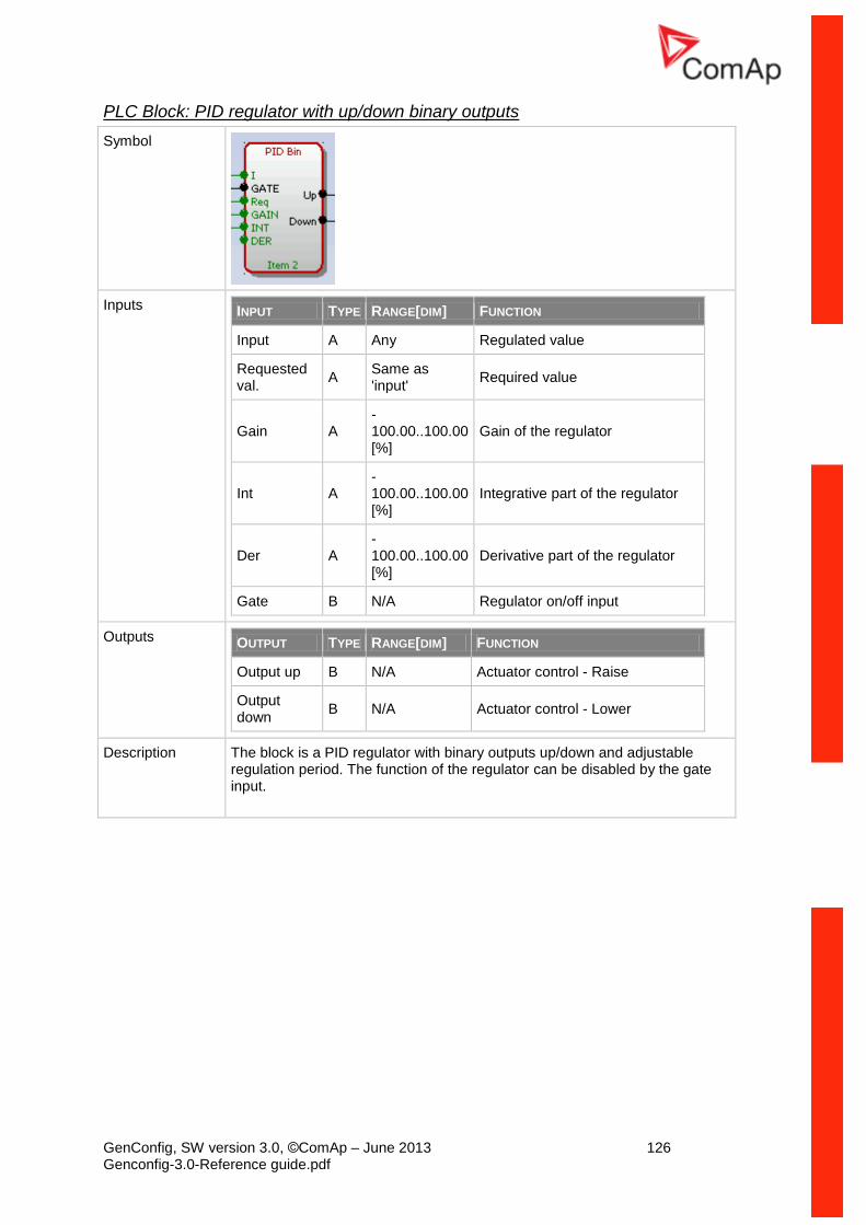
GenConfig, SW version 3.0, ©ComAp – June 2013 126 Genconfig-3.0-Reference guide.pdf
PLC Block: PID regulator with up/down binary outputs
Symbol
Inputs INPUT TYPE RANGE[DIM] FUNCTION
Input A Any Regulated value
Requested val.
A Same as 'input'
Required value
Gain A -100.00..100.00 [%]
Gain of the regulator
Int A -100.00..100.00 [%]
Integrative part of the regulator
Der A -100.00..100.00 [%]
Derivative part of the regulator
Gate B N/A Regulator on/off input
Outputs OUTPUT TYPE RANGE[DIM] FUNCTION
Output up B N/A Actuator control - Raise
Output down
B N/A Actuator control - Lower
Description The block is a PID regulator with binary outputs up/down and adjustable regulation period. The function of the regulator can be disabled by the gate input.
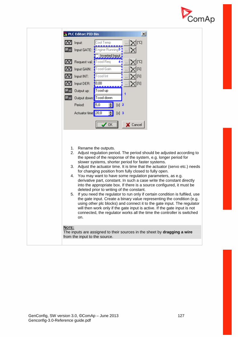
GenConfig, SW version 3.0, ©ComAp – June 2013 127 Genconfig-3.0-Reference guide.pdf
1. Rename the outputs. 2. Adjust regulation period. The period should be adjusted according to
the speed of the response of the system, e.g. longer period for slower systems, shorter period for faster systems.
3. Adjust the actuator time. It is time that the actuator (servo etc.) needs for changing position from fully closed to fully open.
4. You may want to have some regulation parameters, as e.g. derivative part, constant. In such a case write the constant directly into the appropriate box. If there is a source configured, it must be deleted prior to writing of the constant.
5. If you need the regulator to run only if certain condition is fulfiled, use the gate input. Create a binary value representing the condition (e.g. using other plc blocks) and connect it to the gate input. The regulator will then work only if the gate input is active. If the gate input is not connected, the regulator works all the time the controller is switched on.
NOTE: The inputs are assigned to their sources in the sheet by dragging a wire from the input to the source.
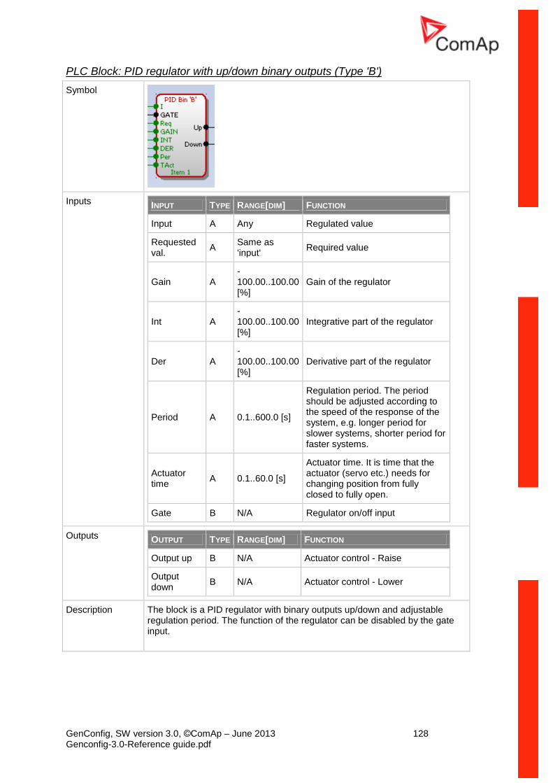
GenConfig, SW version 3.0, ©ComAp – June 2013 128 Genconfig-3.0-Reference guide.pdf
PLC Block: PID regulator with up/down binary outputs (Type 'B')
Symbol
Inputs INPUT TYPE RANGE[DIM] FUNCTION
Input A Any Regulated value
Requested val.
A Same as 'input'
Required value
Gain A -100.00..100.00 [%]
Gain of the regulator
Int A -100.00..100.00 [%]
Integrative part of the regulator
Der A -100.00..100.00 [%]
Derivative part of the regulator
Period A 0.1..600.0 [s]
Regulation period. The period should be adjusted according to the speed of the response of the system, e.g. longer period for slower systems, shorter period for faster systems.
Actuator time
A 0.1..60.0 [s]
Actuator time. It is time that the actuator (servo etc.) needs for changing position from fully closed to fully open.
Gate B N/A Regulator on/off input
Outputs OUTPUT TYPE RANGE[DIM] FUNCTION
Output up B N/A Actuator control - Raise
Output down
B N/A Actuator control - Lower
Description The block is a PID regulator with binary outputs up/down and adjustable regulation period. The function of the regulator can be disabled by the gate input.
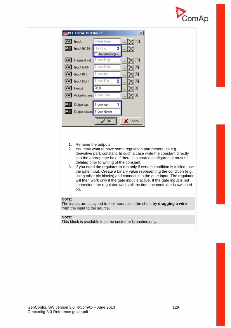
GenConfig, SW version 3.0, ©ComAp – June 2013 129 Genconfig-3.0-Reference guide.pdf
1. Rename the outputs. 2. You may want to have some regulation parameters, as e.g.
derivative part, constant. In such a case write the constant directly into the appropriate box. If there is a source configured, it must be deleted prior to writing of the constant.
3. If you need the regulator to run only if certain condition is fulfiled, use the gate input. Create a binary value representing the condition (e.g. using other plc blocks) and connect it to the gate input. The regulator will then work only if the gate input is active. If the gate input is not connected, the regulator works all the time the controller is switched on.
NOTE: The inputs are assigned to their sources in the sheet by dragging a wire from the input to the source. NOTE: This block is available in some customer branches only.
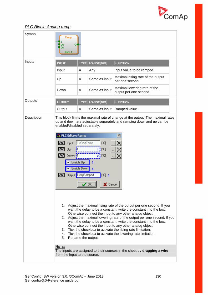
GenConfig, SW version 3.0, ©ComAp – June 2013 130 Genconfig-3.0-Reference guide.pdf
PLC Block: Analog ramp
Symbol
Inputs INPUT TYPE RANGE[DIM] FUNCTION
Input A Any Input value to be ramped.
Up A Same as input Maximal rising rate of the output per one second.
Down A Same as input Maximal lowering rate of the output per one second.
Outputs OUTPUT TYPE RANGE[DIM] FUNCTION
Output A Same as input Ramped value
Description This block limits the maximal rate of change at the output. The maximal rates up and down are adjustable separately and ramping down and up can be enabled/disabled separately.
1. Adjust the maximal rising rate of the output per one second. If you want the delay to be a constant, write the constant into the box. Otherwise connect the input to any other analog object.
2. Adjust the maximal lowering rate of the output per one second. If you want the delay to be a constant, write the constant into the box. Otherwise connect the input to any other analog object.
3. Tick the checkbox to activate the rising rate limitation. 4. Tick the checkbox to activate the lowering rate limitation. 5. Rename the output.
NOTE: The inputs are assigned to their sources in the sheet by dragging a wire from the input to the source.
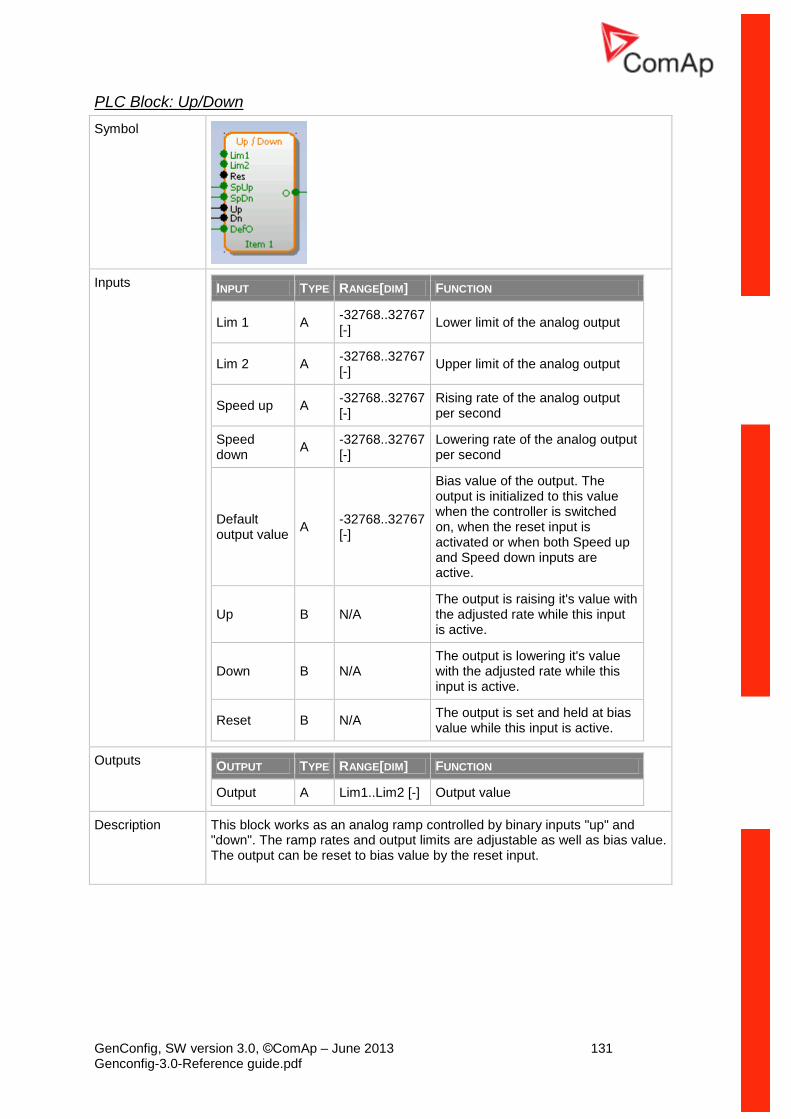
GenConfig, SW version 3.0, ©ComAp – June 2013 131 Genconfig-3.0-Reference guide.pdf
PLC Block: Up/Down
Symbol
Inputs INPUT TYPE RANGE[DIM] FUNCTION
Lim 1 A -32768..32767 [-]
Lower limit of the analog output
Lim 2 A -32768..32767 [-]
Upper limit of the analog output
Speed up A -32768..32767 [-]
Rising rate of the analog output per second
Speed down
A -32768..32767 [-]
Lowering rate of the analog output per second
Default output value
A -32768..32767 [-]
Bias value of the output. The output is initialized to this value when the controller is switched on, when the reset input is activated or when both Speed up and Speed down inputs are active.
Up B N/A The output is raising it's value with the adjusted rate while this input is active.
Down B N/A The output is lowering it's value with the adjusted rate while this input is active.
Reset B N/A The output is set and held at bias value while this input is active.
Outputs OUTPUT TYPE RANGE[DIM] FUNCTION
Output A Lim1..Lim2 [-] Output value
Description This block works as an analog ramp controlled by binary inputs "up" and "down". The ramp rates and output limits are adjustable as well as bias value. The output can be reset to bias value by the reset input.
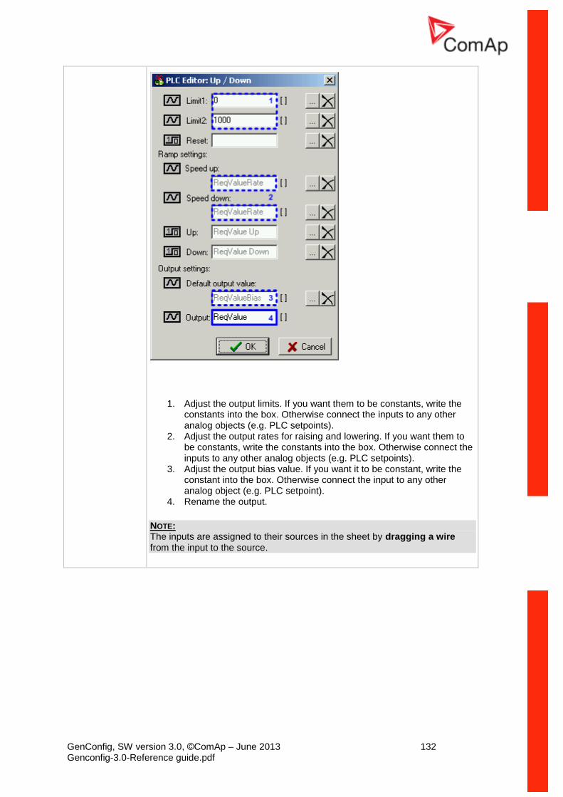
GenConfig, SW version 3.0, ©ComAp – June 2013 132 Genconfig-3.0-Reference guide.pdf
1. Adjust the output limits. If you want them to be constants, write the constants into the box. Otherwise connect the inputs to any other analog objects (e.g. PLC setpoints).
2. Adjust the output rates for raising and lowering. If you want them to be constants, write the constants into the box. Otherwise connect the inputs to any other analog objects (e.g. PLC setpoints).
3. Adjust the output bias value. If you want it to be constant, write the constant into the box. Otherwise connect the input to any other analog object (e.g. PLC setpoint).
4. Rename the output.
NOTE: The inputs are assigned to their sources in the sheet by dragging a wire from the input to the source.
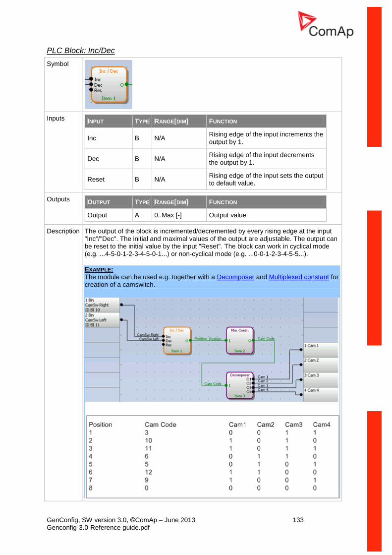
GenConfig, SW version 3.0, ©ComAp – June 2013 133 Genconfig-3.0-Reference guide.pdf
PLC Block: Inc/Dec
Symbol
Inputs INPUT TYPE RANGE[DIM] FUNCTION
Inc B N/A Rising edge of the input increments the output by 1.
Dec B N/A Rising edge of the input decrements the output by 1.
Reset B N/A Rising edge of the input sets the output to default value.
Outputs OUTPUT TYPE RANGE[DIM] FUNCTION
Output A 0..Max [-] Output value
Description The output of the block is incremented/decremented by every rising edge at the input "Inc"/"Dec". The initial and maximal values of the output are adjustable. The output can be reset to the initial value by the input "Reset". The block can work in cyclical mode (e.g. ...4-5-0-1-2-3-4-5-0-1...) or non-cyclical mode (e.g. ...0-0-1-2-3-4-5-5...).
EXAMPLE: The module can be used e.g. together with a Decomposer and Multiplexed constant for creation of a camswitch.
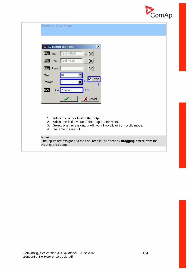
GenConfig, SW version 3.0, ©ComAp – June 2013 134 Genconfig-3.0-Reference guide.pdf
EXAMPLE: CAMSWITCH
1. Adjust the upper limit of the output. 2. Adjust the initial value of the output after reset. 3. Select whether the output will work in cyclic or non-cyclic mode. 4. Rename the output.
NOTE: The inputs are assigned to their sources in the sheet by dragging a wire from the input to the source.
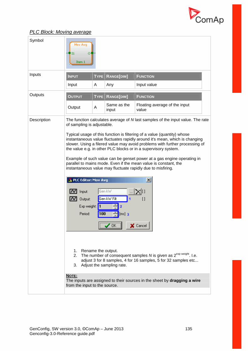
GenConfig, SW version 3.0, ©ComAp – June 2013 135 Genconfig-3.0-Reference guide.pdf
PLC Block: Moving average
Symbol
Inputs INPUT TYPE RANGE[DIM] FUNCTION
Input A Any Input value
Outputs OUTPUT TYPE RANGE[DIM] FUNCTION
Output A Same as the input
Floating average of the input value
Description The function calculates average of N last samples of the input value. The rate of sampling is adjustable.
Typical usage of this function is filtering of a value (quantity) whose instantaneous value fluctuates rapidly around it's mean, which is changing slower. Using a filered value may avoid problems with further processing of the value e.g. in other PLC blocks or in a supervisory system.
Example of such value can be genset power at a gas engine operating in parallel to mains mode. Even if the mean value is constant, the instantaneous value may fluctuate rapidly due to misfiring.
1. Rename the output. 2. The number of consequent samples N is given as 2
exp weight. I.e.
adjust 3 for 8 samples, 4 for 16 samples, 5 for 32 samples etc... 3. Adjust the sampling rate.
NOTE: The inputs are assigned to their sources in the sheet by dragging a wire from the input to the source.
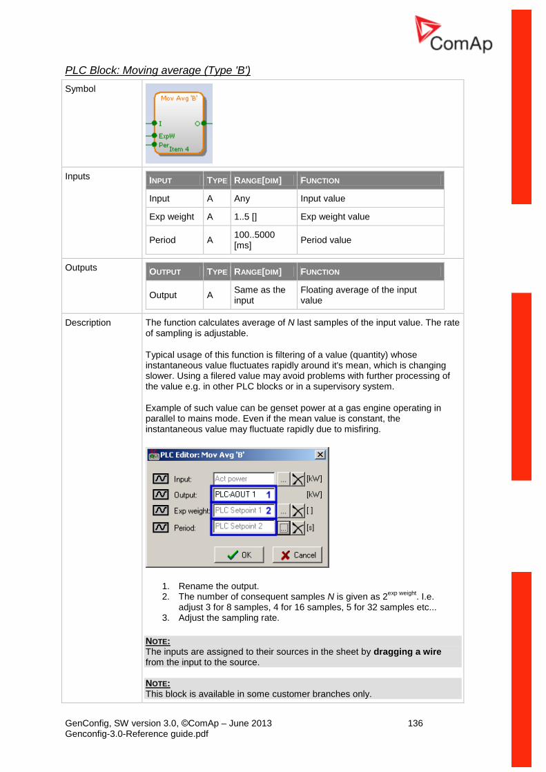
GenConfig, SW version 3.0, ©ComAp – June 2013 136 Genconfig-3.0-Reference guide.pdf
PLC Block: Moving average (Type 'B')
Symbol
Inputs INPUT TYPE RANGE[DIM] FUNCTION
Input A Any Input value
Exp weight A 1..5 [] Exp weight value
Period A 100..5000 [ms]
Period value
Outputs OUTPUT TYPE RANGE[DIM] FUNCTION
Output A Same as the input
Floating average of the input value
Description The function calculates average of N last samples of the input value. The rate of sampling is adjustable.
Typical usage of this function is filtering of a value (quantity) whose instantaneous value fluctuates rapidly around it's mean, which is changing slower. Using a filered value may avoid problems with further processing of the value e.g. in other PLC blocks or in a supervisory system.
Example of such value can be genset power at a gas engine operating in parallel to mains mode. Even if the mean value is constant, the instantaneous value may fluctuate rapidly due to misfiring.
1. Rename the output. 2. The number of consequent samples N is given as 2
exp weight. I.e.
adjust 3 for 8 samples, 4 for 16 samples, 5 for 32 samples etc... 3. Adjust the sampling rate.
NOTE: The inputs are assigned to their sources in the sheet by dragging a wire from the input to the source. NOTE: This block is available in some customer branches only.
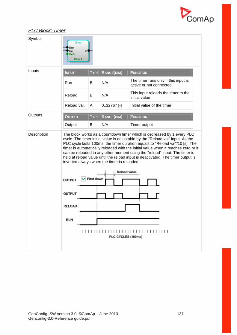
GenConfig, SW version 3.0, ©ComAp – June 2013 137 Genconfig-3.0-Reference guide.pdf
PLC Block: Timer
Symbol
Inputs INPUT TYPE RANGE[DIM] FUNCTION
Run B N/A The timer runs only if this input is active or not connected
Reload B N/A This input reloads the timer to the initial value
Reload val. A 0..32767 [-] Initial value of the timer.
Outputs OUTPUT TYPE RANGE[DIM] FUNCTION
Output B N/A Timer output
Description The block works as a countdown timer which is decreased by 1 every PLC cycle. The timer initial value is adjustable by the "Reload val" input. As the PLC cycle lasts 100ms, the timer duration equals to "Reload val"/10 [s]. The timer is automatically reloaded with the initial value when it reaches zero or it can be reloaded in any other moment using the "reload" input. The timer is held at reload value until the reload input is deactivated. The timer output is inverted always when the timer is reloaded.
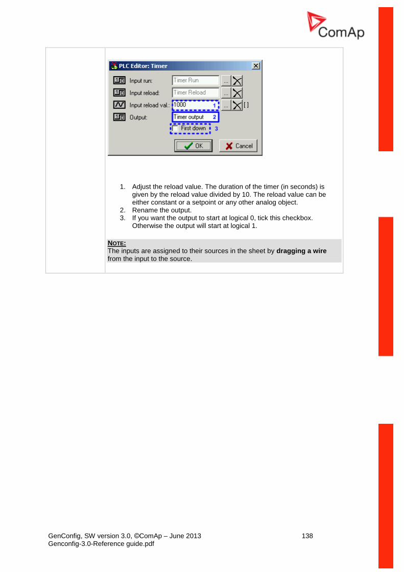
GenConfig, SW version 3.0, ©ComAp – June 2013 138 Genconfig-3.0-Reference guide.pdf
1. Adjust the reload value. The duration of the timer (in seconds) is given by the reload value divided by 10. The reload value can be either constant or a setpoint or any other analog object.
2. Rename the output. 3. If you want the output to start at logical 0, tick this checkbox.
Otherwise the output will start at logical 1.
NOTE: The inputs are assigned to their sources in the sheet by dragging a wire from the input to the source.
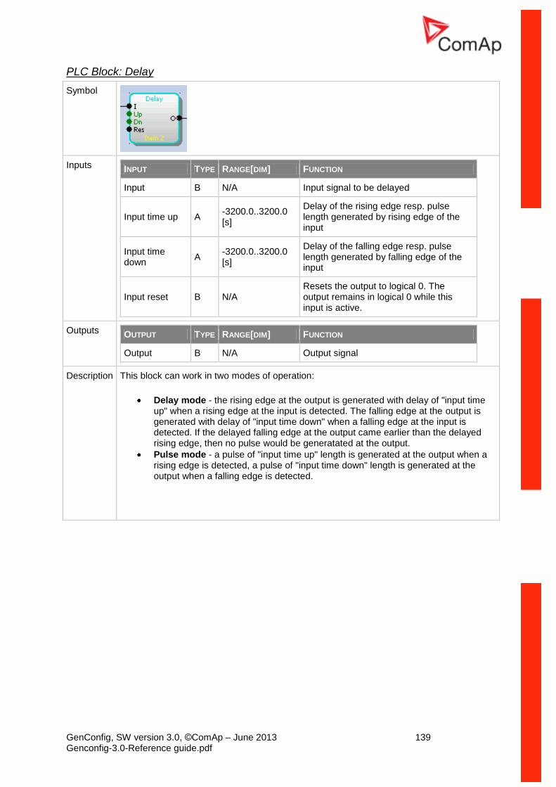
GenConfig, SW version 3.0, ©ComAp – June 2013 139 Genconfig-3.0-Reference guide.pdf
PLC Block: Delay
Symbol
Inputs INPUT TYPE RANGE[DIM] FUNCTION
Input B N/A Input signal to be delayed
Input time up A -3200.0..3200.0 [s]
Delay of the rising edge resp. pulse length generated by rising edge of the input
Input time down
A -3200.0..3200.0 [s]
Delay of the falling edge resp. pulse length generated by falling edge of the input
Input reset B N/A Resets the output to logical 0. The output remains in logical 0 while this input is active.
Outputs OUTPUT TYPE RANGE[DIM] FUNCTION
Output B N/A Output signal
Description This block can work in two modes of operation:
Delay mode - the rising edge at the output is generated with delay of "input time up" when a rising edge at the input is detected. The falling edge at the output is generated with delay of "input time down" when a falling edge at the input is detected. If the delayed falling edge at the output came earlier than the delayed rising edge, then no pulse would be generatated at the output.
Pulse mode - a pulse of "input time up" length is generated at the output when a rising edge is detected, a pulse of "input time down" length is generated at the output when a falling edge is detected.
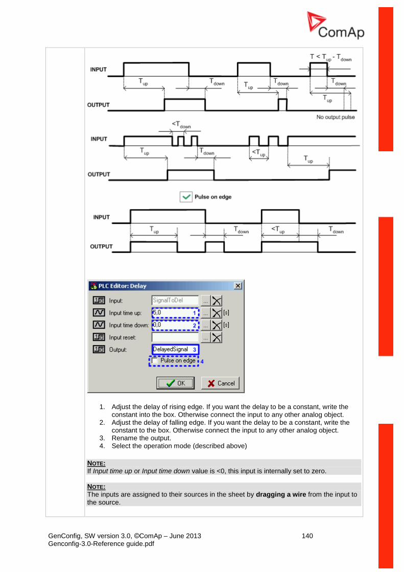
GenConfig, SW version 3.0, ©ComAp – June 2013 140 Genconfig-3.0-Reference guide.pdf
1. Adjust the delay of rising edge. If you want the delay to be a constant, write the constant into the box. Otherwise connect the input to any other analog object.
2. Adjust the delay of falling edge. If you want the delay to be a constant, write the constant to the box. Otherwise connect the input to any other analog object.
3. Rename the output. 4. Select the operation mode (described above)
NOTE: If Input time up or Input time down value is <0, this input is internally set to zero. NOTE: The inputs are assigned to their sources in the sheet by dragging a wire from the input to the source.
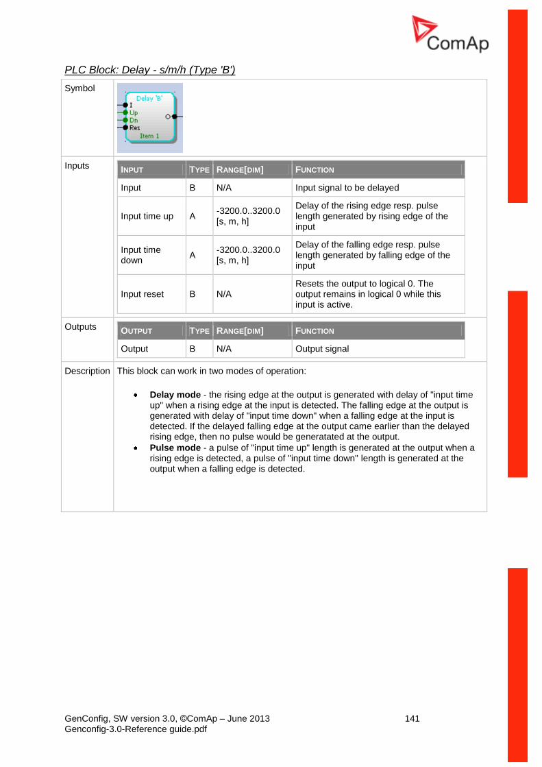
GenConfig, SW version 3.0, ©ComAp – June 2013 141 Genconfig-3.0-Reference guide.pdf
PLC Block: Delay - s/m/h (Type 'B')
Symbol
Inputs INPUT TYPE RANGE[DIM] FUNCTION
Input B N/A Input signal to be delayed
Input time up A -3200.0..3200.0 [s, m, h]
Delay of the rising edge resp. pulse length generated by rising edge of the input
Input time down
A -3200.0..3200.0 [s, m, h]
Delay of the falling edge resp. pulse length generated by falling edge of the input
Input reset B N/A Resets the output to logical 0. The output remains in logical 0 while this input is active.
Outputs OUTPUT TYPE RANGE[DIM] FUNCTION
Output B N/A Output signal
Description This block can work in two modes of operation:
Delay mode - the rising edge at the output is generated with delay of "input time up" when a rising edge at the input is detected. The falling edge at the output is generated with delay of "input time down" when a falling edge at the input is detected. If the delayed falling edge at the output came earlier than the delayed rising edge, then no pulse would be generatated at the output.
Pulse mode - a pulse of "input time up" length is generated at the output when a rising edge is detected, a pulse of "input time down" length is generated at the output when a falling edge is detected.
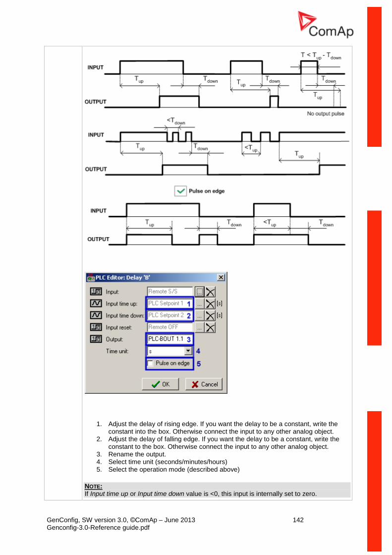
GenConfig, SW version 3.0, ©ComAp – June 2013 142 Genconfig-3.0-Reference guide.pdf
1. Adjust the delay of rising edge. If you want the delay to be a constant, write the constant into the box. Otherwise connect the input to any other analog object.
2. Adjust the delay of falling edge. If you want the delay to be a constant, write the constant to the box. Otherwise connect the input to any other analog object.
3. Rename the output. 4. Select time unit (seconds/minutes/hours) 5. Select the operation mode (described above)
NOTE: If Input time up or Input time down value is <0, this input is internally set to zero.
GenConfig, SW version 3.0, ©ComAp – June 2013 143 Genconfig-3.0-Reference guide.pdf
NOTE: The inputs are assigned to their sources in the sheet by dragging a wire from the input to the source. NOTE: This block is available in version 3.0 and later.
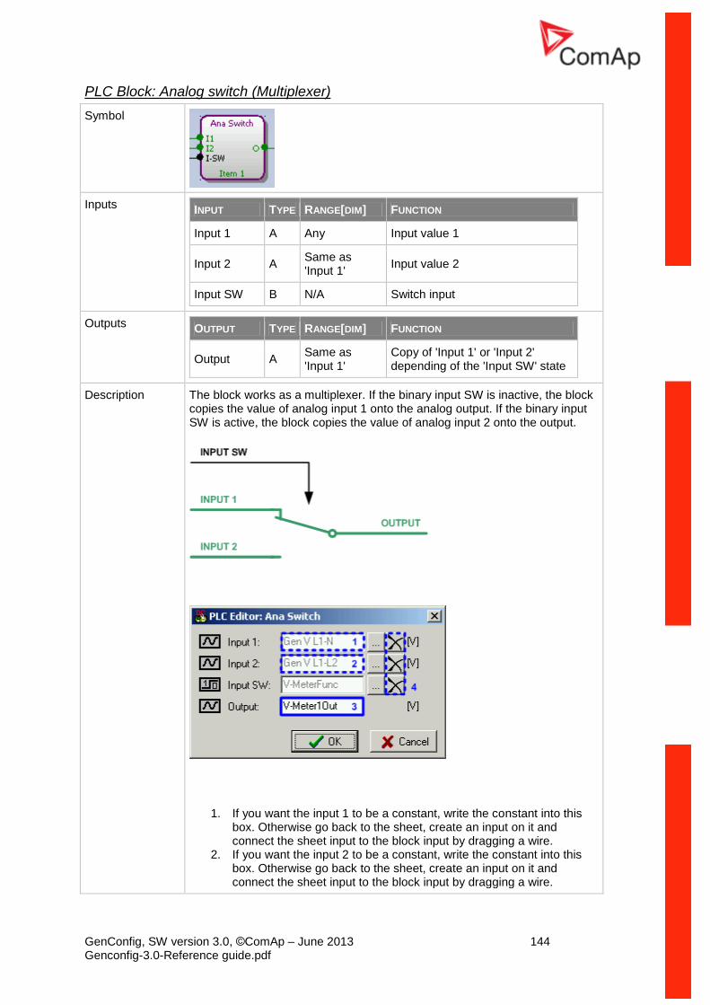
GenConfig, SW version 3.0, ©ComAp – June 2013 144 Genconfig-3.0-Reference guide.pdf
PLC Block: Analog switch (Multiplexer)
Symbol
Inputs INPUT TYPE RANGE[DIM] FUNCTION
Input 1 A Any Input value 1
Input 2 A Same as 'Input 1'
Input value 2
Input SW B N/A Switch input
Outputs OUTPUT TYPE RANGE[DIM] FUNCTION
Output A Same as 'Input 1'
Copy of 'Input 1' or 'Input 2' depending of the 'Input SW' state
Description The block works as a multiplexer. If the binary input SW is inactive, the block copies the value of analog input 1 onto the analog output. If the binary input SW is active, the block copies the value of analog input 2 onto the output.
1. If you want the input 1 to be a constant, write the constant into this box. Otherwise go back to the sheet, create an input on it and connect the sheet input to the block input by dragging a wire.
2. If you want the input 2 to be a constant, write the constant into this box. Otherwise go back to the sheet, create an input on it and connect the sheet input to the block input by dragging a wire.
GenConfig, SW version 3.0, ©ComAp – June 2013 145 Genconfig-3.0-Reference guide.pdf
3. Rename the output.
NOTE: Press the button (4) if you need to delete the currently configured source from the box. NOTE: The inputs are assigned to their sources in the sheet by dragging a wire from the input to the source.
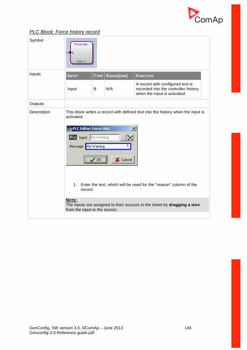
GenConfig, SW version 3.0, ©ComAp – June 2013 146 Genconfig-3.0-Reference guide.pdf
PLC Block: Force history record
Symbol
Inputs INPUT TYPE RANGE[DIM] FUNCTION
Input B N/A A record with configured text is recorded into the controller history when the input is activated.
Outputs
Description This block writes a record with defined text into the history when the input is activated.
1. Enter the text, which will be used for the "reason" column of the record.
NOTE: The inputs are assigned to their sources in the sheet by dragging a wire from the input to the source.
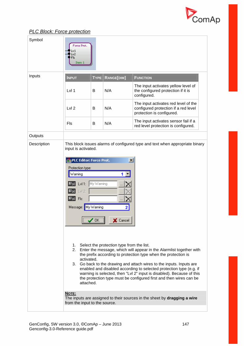
GenConfig, SW version 3.0, ©ComAp – June 2013 147 Genconfig-3.0-Reference guide.pdf
PLC Block: Force protection
Symbol
Inputs INPUT TYPE RANGE[DIM] FUNCTION
Lvl 1 B N/A The input activates yellow level of the configured protection if it is configured.
Lvl 2 B N/A The input activates red level of the configured protection if a red level protection is configured.
Fls B N/A The input activates sensor fail if a red level protection is configured.
Outputs
Description This block issues alarms of configured type and text when appropriate binary input is activated.
1. Select the protection type from the list. 2. Enter the message, which will appear in the Alarmlist together with
the prefix according to protection type when the protection is activated.
3. Go back to the drawing and attach wires to the inputs. Inputs are enabled and disabled according to selected protection type (e.g. if warning is selected, then "Lvl 2" input is disabled). Because of this the protection type must be configured first and then wires can be attached.
NOTE: The inputs are assigned to their sources in the sheet by dragging a wire from the input to the source.
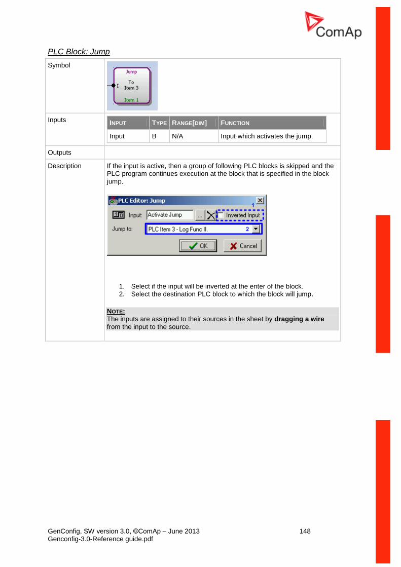
GenConfig, SW version 3.0, ©ComAp – June 2013 148 Genconfig-3.0-Reference guide.pdf
PLC Block: Jump
Symbol
Inputs INPUT TYPE RANGE[DIM] FUNCTION
Input B N/A Input which activates the jump.
Outputs
Description If the input is active, then a group of following PLC blocks is skipped and the PLC program continues execution at the block that is specified in the block jump.
1. Select if the input will be inverted at the enter of the block. 2. Select the destination PLC block to which the block will jump.
NOTE: The inputs are assigned to their sources in the sheet by dragging a wire from the input to the source.
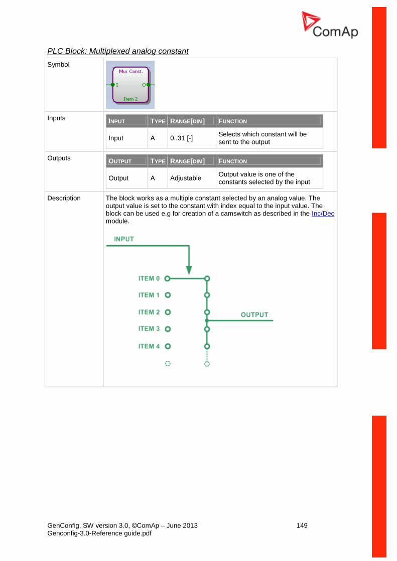
GenConfig, SW version 3.0, ©ComAp – June 2013 149 Genconfig-3.0-Reference guide.pdf
PLC Block: Multiplexed analog constant
Symbol
Inputs INPUT TYPE RANGE[DIM] FUNCTION
Input A 0..31 [-] Selects which constant will be sent to the output
Outputs OUTPUT TYPE RANGE[DIM] FUNCTION
Output A Adjustable Output value is one of the constants selected by the input
Description The block works as a multiple constant selected by an analog value. The output value is set to the constant with index equal to the input value. The block can be used e.g for creation of a camswitch as described in the Inc/Dec module.

GenConfig, SW version 3.0, ©ComAp – June 2013 150 Genconfig-3.0-Reference guide.pdf
1. Rename the output. 2. Adjust resolution and dimension. 3. Use the buttons to add/remove constants (up to 32). 4. Adjust values of the constants. The column "Item" (4.1) represents
indexes of the constants, which are used for selecting of the active constant. The value of the constant can be entered either in decimal form (4.2) or in binary form (4.3).
NOTE: The inputs are assigned to their sources in the sheet by dragging a wire from the input to the source.
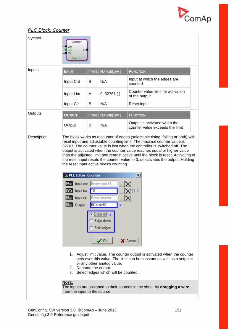
GenConfig, SW version 3.0, ©ComAp – June 2013 151 Genconfig-3.0-Reference guide.pdf
PLC Block: Counter
Symbol
Inputs INPUT TYPE RANGE[DIM] FUNCTION
Input Cnt B N/A Input at which the edges are counted
Input Lim A 0..32767 [-] Counter value limit for activation of the output.
Input Clr B N/A Reset input
Outputs OUTPUT TYPE RANGE[DIM] FUNCTION
Output B N/A Output is activated when the counter value exceeds the limit
Description The block works as a counter of edges (selectable rising, falling or both) with reset input and adjustable counting limit. The maximal counter value is 32767. The counter value is lost when the controller is switched off. The output is activated when the counter value reaches equal or higher value than the adjusted limit and remain active until the block is reset. Activating of the reset input resets the counter value to 0, deactivates the output. Holding the reset input active blocks counting.
1. Adjust limit value. The counter output is activated when the counter gets over this value. The limit can be constant as well as a setpoint or any other analog value.
2. Rename the output. 3. Select edges which will be counted.
NOTE: The inputs are assigned to their sources in the sheet by dragging a wire from the input to the source.
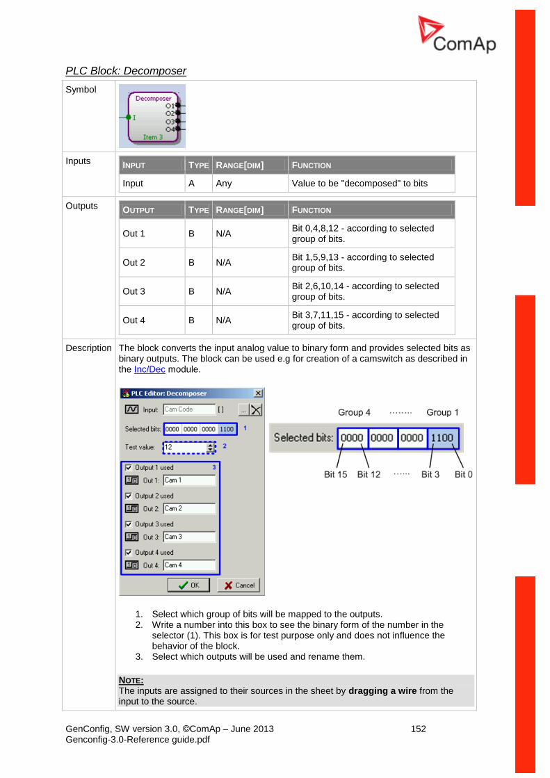
GenConfig, SW version 3.0, ©ComAp – June 2013 152 Genconfig-3.0-Reference guide.pdf
PLC Block: Decomposer
Symbol
Inputs INPUT TYPE RANGE[DIM] FUNCTION
Input A Any Value to be "decomposed" to bits
Outputs OUTPUT TYPE RANGE[DIM] FUNCTION
Out 1 B N/A Bit 0,4,8,12 - according to selected group of bits.
Out 2 B N/A Bit 1,5,9,13 - according to selected group of bits.
Out 3 B N/A Bit 2,6,10,14 - according to selected group of bits.
Out 4 B N/A Bit 3,7,11,15 - according to selected group of bits.
Description The block converts the input analog value to binary form and provides selected bits as binary outputs. The block can be used e.g for creation of a camswitch as described in the Inc/Dec module.
1. Select which group of bits will be mapped to the outputs. 2. Write a number into this box to see the binary form of the number in the
selector (1). This box is for test purpose only and does not influence the behavior of the block.
3. Select which outputs will be used and rename them.
NOTE: The inputs are assigned to their sources in the sheet by dragging a wire from the input to the source.
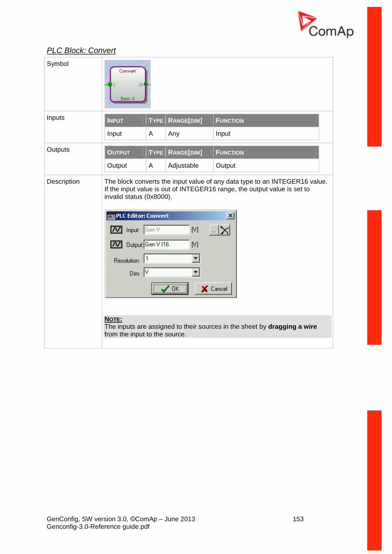
GenConfig, SW version 3.0, ©ComAp – June 2013 153 Genconfig-3.0-Reference guide.pdf
PLC Block: Convert
Symbol
Inputs INPUT TYPE RANGE[DIM] FUNCTION
Input A Any Input
Outputs OUTPUT TYPE RANGE[DIM] FUNCTION
Output A Adjustable Output
Description The block converts the input value of any data type to an INTEGER16 value. If the input value is out of INTEGER16 range, the output value is set to invalid status (0x8000).
NOTE: The inputs are assigned to their sources in the sheet by dragging a wire from the input to the source.