Embed Size (px)
Citation preview
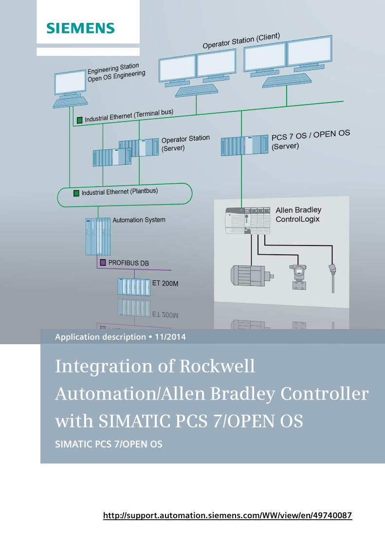
http://support.automation.siemens.com/WW/view/en/49740087
Application description 11/2014
Integration of Rockwell
Automation/Allen Bradley Controller
with SIMATIC PCS 7/OPEN OS SIMATIC PCS 7/OPEN OS
Warranty and liability
ControlLogix Integration in PCS 7 Entry ID: 49740087, V1.0, 11/2014 2
S
iem
en
s A
G 2
01
4 A
ll ri
gh
ts r
ese
rve
d
Warranty and liability
Note The Application Examples are not binding and do not claim to be complete regarding the circuits shown, equipping and any eventuality. The Application Examples do not represent customer-specific solutions. They are only intended to provide support for typical applications. You are responsible for ensuring that the described products are used correctly. These application examples do not relieve you of the responsibility to use safe practices in application, installation, operation and maintenance. When using these Application Examples, you recognize that we cannot be held liable for any damages/claims beyond the liability clause described. We reserve the right to make changes to these Application Examples at any time without prior notice. If there are any deviations between the recommendations provided in these application examples and other Siemens publications – e.g. Catalogs – the contents of the other documents have priority.
We do not accept any liability for the information contained in this document.
Any claims against us – based on whatever legal reason – resulting from the use of the examples, information, programs, engineering and performance data etc., described in this Application Example shall be excluded. Such an exclusion shall not apply in the case of mandatory liability, e.g. under the German Product Liability Act (“Produkthaftungsgesetz”), in case of intent, gross negligence, or injury of life, body or health, guarantee for the quality of a product, fraudulent concealment of a deficiency or breach of a condition which goes to the root of the contract (“wesentliche Vertragspflichten”). The damages for a breach of a substantial contractual obligation are, however, limited to the foreseeable damage, typical for the type of contract, except in the event of intent or gross negligence or injury to life, body or health. The above provisions do not imply a change of the burden of proof to your detriment.
Any form of duplication or distribution of these Application Examples or excerpts hereof is prohibited without the expressed consent of Siemens Industry Sector.
Security infor-
mation
Siemens provides products and solutions with industrial security functions that support the secure operation of plants, solutions, machines, equipment and/or networks. They are important components of a holistic industrial security concept. The products and solutions from Siemens undergo continuous development with this factor in mind. Siemens recommends strongly that you regularly check for product updates.
For the secure operation of Siemens products and solutions, it is necessary to take suitable preventive action (e.g. cell protection concept) and integrate each component into a holistic, state-of-the-art industrial security concept. Third-party products that may be in use should also be considered. For more information about industrial security, visit http://www.siemens.com/industrialsecurity.
To stay informed about product updates as they occur, sign up for a product-specific newsletter. For more information, visit http://support.automation.siemens.com.
Table of contents
ControlLogix Integration in PCS 7 Entry ID: 49740087, V1.0, 11/2014 3
S
iem
en
s A
G 2
01
4 A
ll ri
gh
ts r
ese
rve
d
Table of contents Warranty and liability ............................................................................................... 2
1 Task................................................................................................................. 4
1.1 Overview ........................................................................................... 4
2 Solution........................................................................................................... 5
2.1 Overview ........................................................................................... 5 2.2 Description of the core functionality .................................................... 6 2.3 Configuration guide............................................................................ 7 2.4 Editors ............................................................................................. 10 2.4.1 PCS 7 DBA AS Node Type Wizard .................................................. 10 2.4.2 PCS 7 DBA ..................................................................................... 11 2.4.3 PCS 7 DBA Type Editor ................................................................... 12
3 Connecting an Allen Bradley ControlLogix controller ................................ 13
3.1 Acquiring data ................................................................................. 14 3.2 Generating OS block icons and faceplates ....................................... 16 3.3 Generating the AS node with the AS Node Type Wizard .................. 18 3.3.1 General tab ..................................................................................... 18 3.3.2 Instance Source tab ......................................................................... 19 3.3.3 Connections tab............................................................................... 20 3.3.4 Addressing tab ................................................................................ 23 3.4 Creating the AS node ...................................................................... 25 3.5 Generating AS object types ............................................................. 27 3.5.1 Creating a new type ......................................................................... 28 3.5.2 Including default types ..................................................................... 29 3.5.3 Creating tags ................................................................................... 30 3.5.4 Configuring alarms .......................................................................... 32 3.5.5 Attributes ......................................................................................... 35 3.6 Creating ASO instances................................................................... 36
4 Configuring the PC station with the DBA .................................................... 39
4.1 Adding a PC Station ........................................................................ 39 4.2 Creating a plant hierarchy ................................................................ 42 4.2.1 Customizing hierarchy settings ........................................................ 42 4.2.2 Synchronizing the plant hierarchy .................................................... 44 4.2.3 Extending the plant hierarchy ........................................................... 45 4.2.4 Assigning hierarchy folders to an OS ............................................... 46 4.2.5 Assigning AS object instances ......................................................... 46 4.2.6 Editing object attributes.................................................................... 47 4.2.7 Compile OS ..................................................................................... 48 4.3 PCS 7 operator station..................................................................... 50
5 Literature ...................................................................................................... 52
6 History .......................................................................................................... 52
1 Task
1.1 Overview
ControlLogix Integration in PCS 7 Entry ID: 49740087, V1.0, 11/2014 4
S
iem
en
s A
G 2
01
4 A
ll ri
gh
ts r
ese
rve
d
1 Task
1.1 Overview
Introduction
System landscapes that have grown over time often consist of heterogeneous automation technologies. This results in the requirement that devices which contain controllers from competitors can also be operated and monitored using a PCS 7 operator system.
SIMATIC PCS 7/OPEN OS is a PCS 7 option with which controllers that do not belong to the spectrum of SIMATIC PCS 7 system components can be integrated into the PCS 7 process control.
PCS 7/OPEN OS V8.1 enables the data exchange between the PCS 7 operator station and various automation systems via the existing WinCC channels or via the OPC channel. For third-party systems that can only be integrated via the OPC channel, only the appropriate OPC server for the particular controller type is necessary. PCS 7/OPEN OS supports the data exchange with the controllers via OPC DA and OPC A&E.
The core of PCS 7/OPEN OS is based on the database automation software (DBA) familiar from other OS options. This software is mainly composed of the following components:
SIMATIC PCS 7 OS engineering and runtime software
PCS 7/OPEN OS DBA data base automation software
PCS 7/OPEN OS runtime software option
The supplied base functionality of PCS 7 OPEN/OS allows configuration engineers to effectively integrate the existing third-party controllers into the process control using the PCS 7 operator system. This gives operators the option of operating and monitoring the entire system from a single operator system, even if it contains package units from third-party manufacturers or PUs with Rockwell Automation/ Allen Bradley ControlLogix controllers.
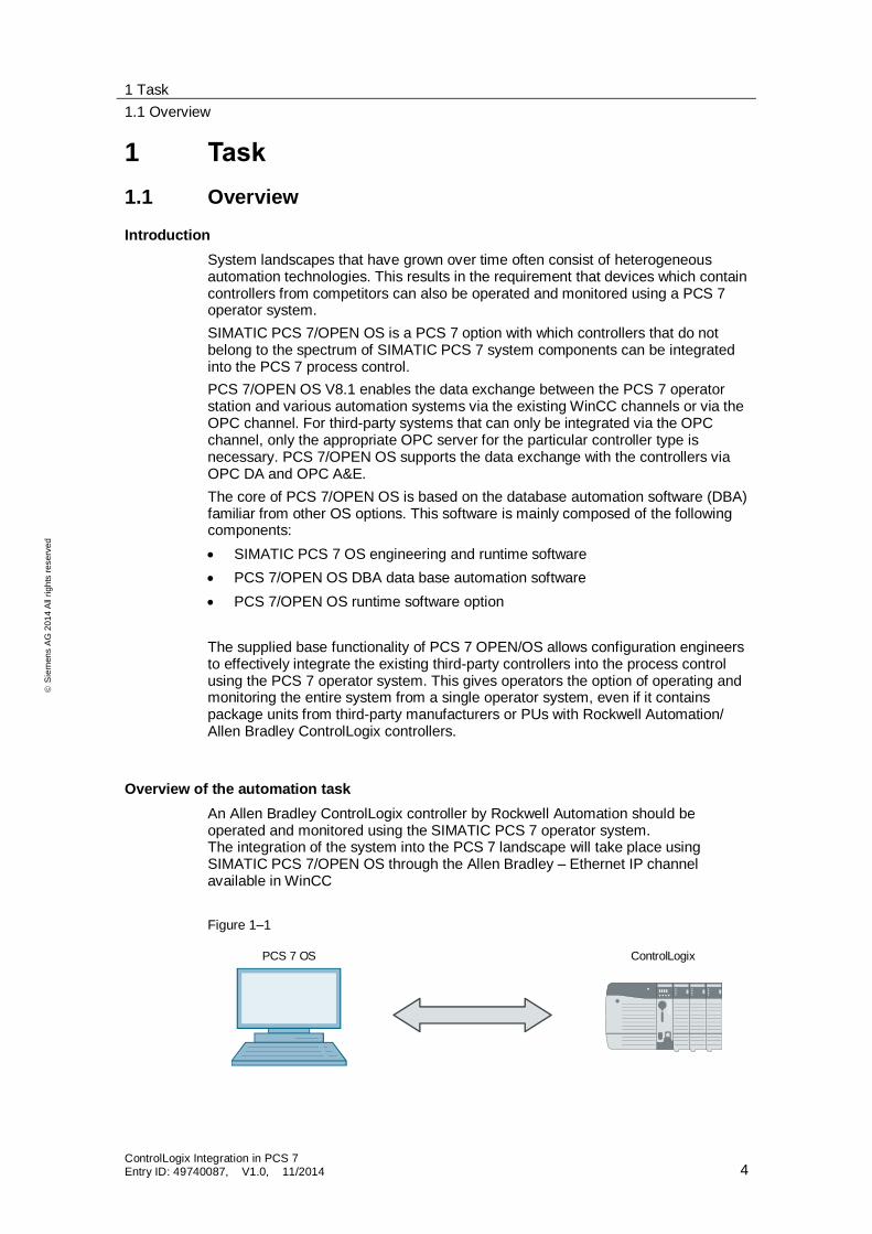
Overview of the automation task
An Allen Bradley ControlLogix controller by Rockwell Automation should be operated and monitored using the SIMATIC PCS 7 operator system. The integration of the system into the PCS 7 landscape will take place using SIMATIC PCS 7/OPEN OS through the Allen Bradley – Ethernet IP channel available in WinCC
Figure 1–1
PCS 7 OS ControlLogix
2 Solution
2.1 Overview
ControlLogix Integration in PCS 7 Entry ID: 49740087, V1.0, 11/2014 5
S
iem
en
s A
G 2
01
4 A
ll ri
gh
ts r
ese
rve
d
2 Solution Using the PCS 7 SIMATIC PCS 7/OPEN OS option, this application example will show you how you can effectively integrate third-party controllers into the PCS 7 system landscape.
2.1 Overview
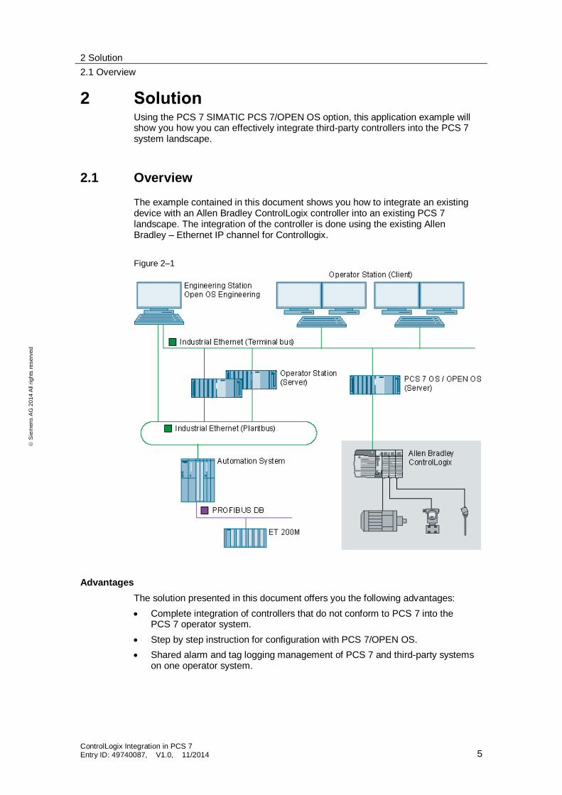
The example contained in this document shows you how to integrate an existing device with an Allen Bradley ControlLogix controller into an existing PCS 7 landscape. The integration of the controller is done using the existing Allen Bradley – Ethernet IP channel for Controllogix.
Figure 2–1
Advantages
The solution presented in this document offers you the following advantages:
Complete integration of controllers that do not conform to PCS 7 into the PCS 7 operator system.
Step by step instruction for configuration with PCS 7/OPEN OS.
Shared alarm and tag logging management of PCS 7 and third-party systems on one operator system.
2 Solution
2.2 Description of the core functionality
ControlLogix Integration in PCS 7 Entry ID: 49740087, V1.0, 11/2014 6
S
iem
en
s A
G 2
01
4 A
ll ri
gh
ts r
ese
rve
d
Required knowledge
The following basic knowledge is required:
Systems configuration with PCS 7 AS engineering
Generation of a visualization with PCS 7 OS engineering
Basic knowledge of the third-party system
2.2 Description of the core functionality
A core component for the PCS 7/OPEN OS engineering is the PCS 7/OPEN OS DBA database automation software.
The DBA generates OS data such as:
Plant hierarchy
Tags and archive tags
Connections
Alarms and messages
The DBA can use the channels available in the PCS 7 OS to connect the systems that are not PCS 7-conform. For example, drivers are integrated in WinCC for the following third-party controllers:
SIMATIC 505
Allen Bradley
Mitsubishi
…
In this application, an Allen Bradley ControlLogix controller by Rockwell Automation is connected via the Allen Bradley – Ethernet IP driver, available in WinCC.
Third-party systems for which no special connections exist can use the OPC or Modbus TCP open standards.
2 Solution
2.3 Configuration guide
ControlLogix Integration in PCS 7 Entry ID: 49740087, V1.0, 11/2014 7
S
iem
en
s A
G 2
01
4 A
ll ri
gh
ts r
ese
rve
d
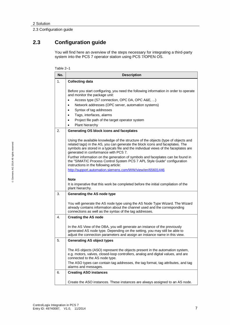
2.3 Configuration guide
You will find here an overview of the steps necessary for integrating a third-party system into the PCS 7 operator station using PCS 7/OPEN OS.
Table 2–1
No. Description
1. Collecting data
Before you start configuring, you need the following information in order to operate and monitor the package unit:
Access type (S7 connection, OPC DA, OPC A&E, ...)
Network addresses (OPC server, automation systems)
Syntax of tag addresses
Tags, interfaces, alarms
Project file path of the target operator system
Plant hierarchy
2. Generating OS block icons and faceplates
Using the available knowledge of the structure of the objects (type of objects and related tags) in the AS, you can generate the block icons and faceplates. The symbols are stored in a typicals file and the individual views of the faceplates are generated in conformance with PCS 7.
Further information on the generation of symbols and faceplates can be found in the "SIMATIC Process Control System PCS 7 APL Style Guide" configuration instructions in the following article:
http://support.automation.siemens.com/WW/view/en/65601446
Note
It is imperative that this work be completed before the initial compilation of the plant hierarchy.
3. Generating the AS node type
You will generate the AS node type using the AS Node Type Wizard. The Wizard already contains information about the channel used and the corresponding connections as well as the syntax of the tag addresses.
4. Creating the AS node
In the AS View of the DBA, you will generate an instance of the previously generated AS node type. Depending on the setting, you may still be able to adjust the connection parameters and assign an instance name in this view.
5. Generating AS object types
The AS objects (ASO) represent the objects present in the automation system, e.g. motors, valves, closed-loop controllers, analog and digital values, and are connected to the AS node type.
The ASO types can contain tag addresses, the tag format, tag attributes, and tag alarms and messages.
6. Creating ASO instances
Create the ASO instances. These instances are always assigned to an AS node.

2 Solution
2.3 Configuration guide
ControlLogix Integration in PCS 7 Entry ID: 49740087, V1.0, 11/2014 8
S
iem
en
s A
G 2
01
4 A
ll ri
gh
ts r
ese
rve
d
7. Creating a PC station
In the PC Station View of the DBA, you can define the OS project to which the data will be compiled. Here, you will set the project path of the target system and also specify a data log if one exists.
8. Specifying the plant hierarchy
An existing plant hierarchy can be read out from the SIMATIC project and synchronized with the DBA project. In the Plant View of the DBA, you can then create additional hierarchy folders and subsequently synchronize them with the SIMATIC project again.
9. Assigning ASO instances to the plant hierarchy
Drag the ASO instance to the corresponding hierarchy folder in the Plant View. By doing so, you create the relation of the AS objects to the operator system.
Depending on the mode of configuration, you may still be able to assign or adjust tag addresses and attributes.
10. Compiling the DBA project
This process roughly corresponds to that of the OS compilation from the SIMATIC Manager. Here, the necessary connections, tags, messages and icons are created in the OS project.
11. Loading the OS and starting the runtime
If all sequences have been executed properly, the OS project can be loaded and the OS runtime can be started.
2 Solution
2.3 Configuration guide
ControlLogix Integration in PCS 7 Entry ID: 49740087, V1.0, 11/2014 9
S
iem
en
s A
G 2
01
4 A
ll ri
gh
ts r
ese
rve
d
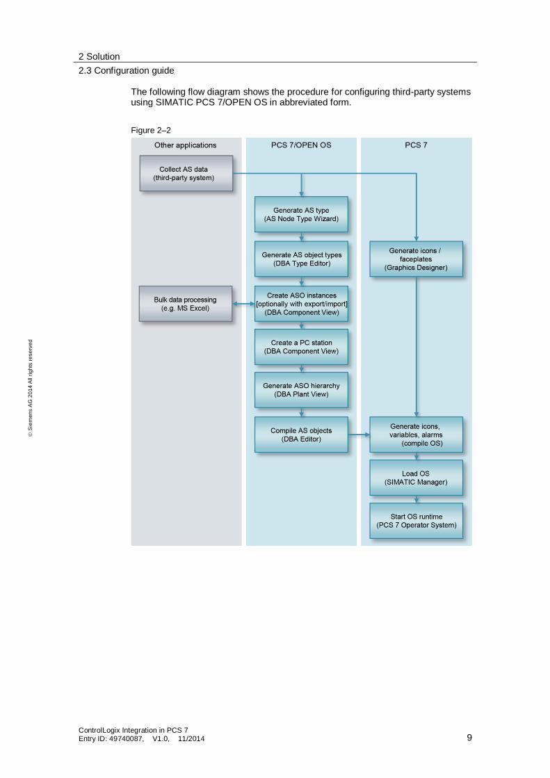
The following flow diagram shows the procedure for configuring third-party systems using SIMATIC PCS 7/OPEN OS in abbreviated form.
Figure 2–2

2 Solution
2.4 Editors
ControlLogix Integration in PCS 7 Entry ID: 49740087, V1.0, 11/2014 10
S
iem
en
s A
G 2
01
4 A
ll ri
gh
ts r
ese
rve
d
2.4 Editors
PCS 7/OPEN OS includes the following editors, which are briefly described below:
PCS 7 DBA AS Node Type Wizard
PCS 7 DBA
PCS 7 DBA Type Editor
2.4.1 PCS 7 DBA AS Node Type Wizard
You will generate the AS node types using the AS Node Type Wizard. Here, the following information will be stored:
AS name
Typical picture
Instance source (DBA or XML)
Connection parameters
Address syntax
You can start the AS Node Type Wizard at "Start > Programs > Siemens Automation > SIMATIC > DBA > PCS 7 DBA ASNodeWizard".
You will find detailed information in the "PCS 7 Open OS Engineering Workflow Guide" manual. The manuals are copied to your system during the OPEN OS installation.
Figure 2–3
2 Solution
2.4 Editors
ControlLogix Integration in PCS 7 Entry ID: 49740087, V1.0, 11/2014 11
S
iem
en
s A
G 2
01
4 A
ll ri
gh
ts r
ese
rve
d
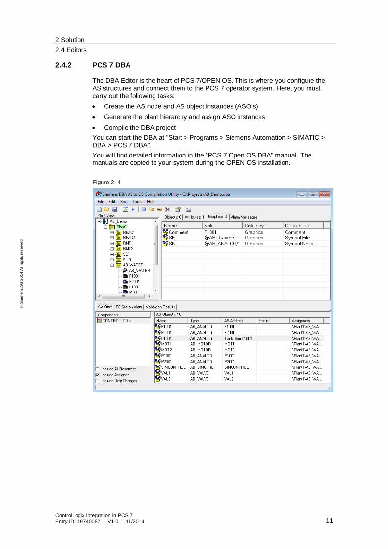
2.4.2 PCS 7 DBA
The DBA Editor is the heart of PCS 7/OPEN OS. This is where you configure the AS structures and connect them to the PCS 7 operator system. Here, you must carry out the following tasks:
Create the AS node and AS object instances (ASO's)
Generate the plant hierarchy and assign ASO instances
Compile the DBA project
You can start the DBA at "Start > Programs > Siemens Automation > SIMATIC > DBA > PCS 7 DBA".
You will find detailed information in the "PCS 7 Open OS DBA" manual. The manuals are copied to your system during the OPEN OS installation.
Figure 2–4
2 Solution
2.4 Editors
ControlLogix Integration in PCS 7 Entry ID: 49740087, V1.0, 11/2014 12
S
iem
en
s A
G 2
01
4 A
ll ri
gh
ts r
ese
rve
d
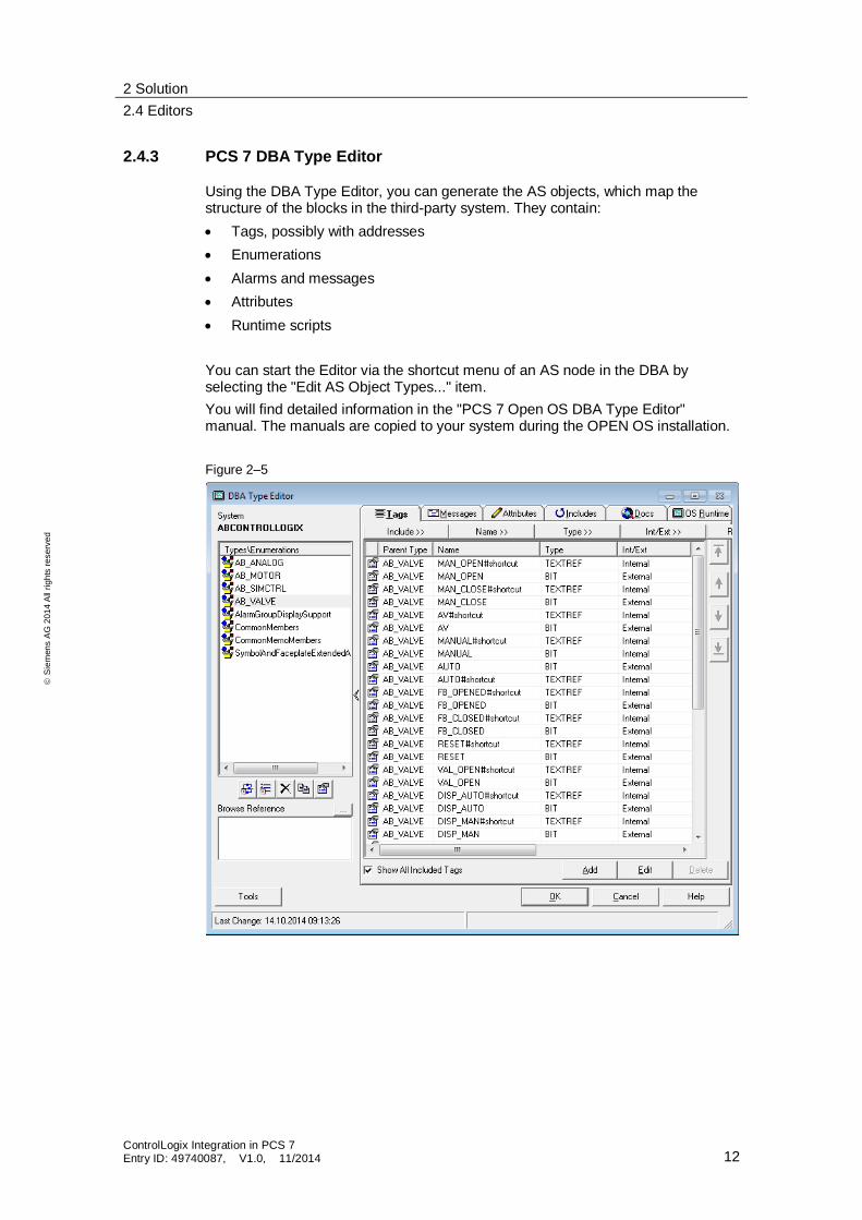
2.4.3 PCS 7 DBA Type Editor
Using the DBA Type Editor, you can generate the AS objects, which map the structure of the blocks in the third-party system. They contain:
Tags, possibly with addresses
Enumerations
Alarms and messages
Attributes
Runtime scripts
You can start the Editor via the shortcut menu of an AS node in the DBA by selecting the "Edit AS Object Types..." item.
You will find detailed information in the "PCS 7 Open OS DBA Type Editor" manual. The manuals are copied to your system during the OPEN OS installation.
Figure 2–5
3 Connecting an Allen Bradley ControlLogix controller
2.4 Editors
ControlLogix Integration in PCS 7 Entry ID: 49740087, V1.0, 11/2014 13
S
iem
en
s A
G 2
01
4 A
ll ri
gh
ts r
ese
rve
d
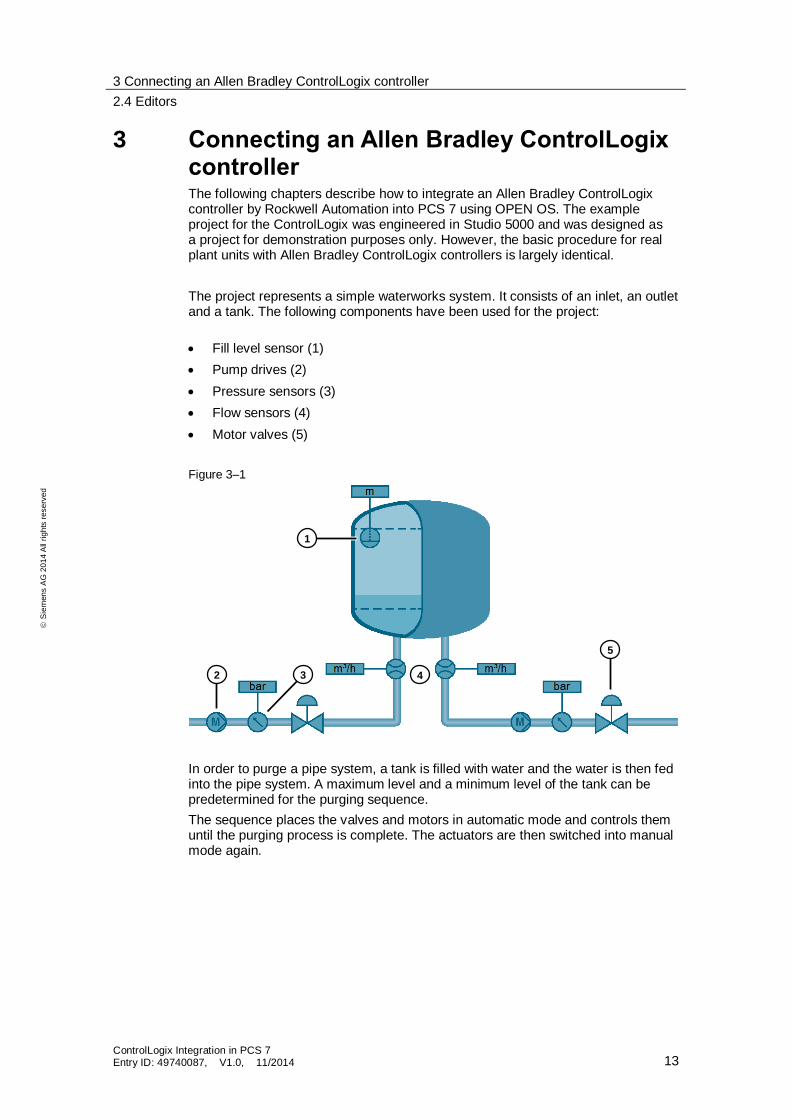
3 Connecting an Allen Bradley ControlLogix controller The following chapters describe how to integrate an Allen Bradley ControlLogix controller by Rockwell Automation into PCS 7 using OPEN OS. The example project for the ControlLogix was engineered in Studio 5000 and was designed as a project for demonstration purposes only. However, the basic procedure for real plant units with Allen Bradley ControlLogix controllers is largely identical.
The project represents a simple waterworks system. It consists of an inlet, an outlet and a tank. The following components have been used for the project:
Fill level sensor (1)
Pump drives (2)
Pressure sensors (3)
Flow sensors (4)
Motor valves (5)
Figure 3–1
In order to purge a pipe system, a tank is filled with water and the water is then fed into the pipe system. A maximum level and a minimum level of the tank can be predetermined for the purging sequence.
The sequence places the valves and motors in automatic mode and controls them until the purging process is complete. The actuators are then switched into manual mode again.
1
2 3 4
5
3 Connecting an Allen Bradley ControlLogix controller
3.1 Acquiring data
ControlLogix Integration in PCS 7 Entry ID: 49740087, V1.0, 11/2014 14
S
iem
en
s A
G 2
01
4 A
ll ri
gh
ts r
ese
rve
d
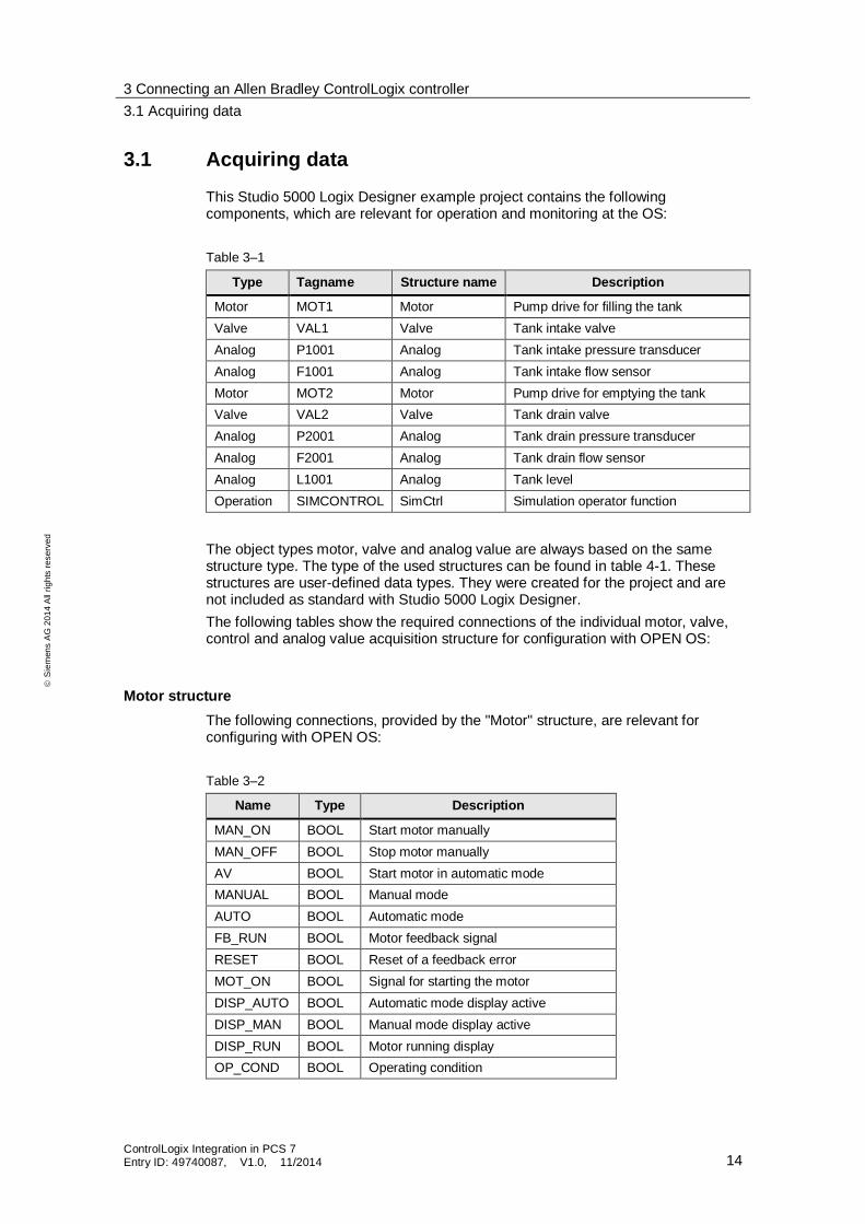
3.1 Acquiring data
This Studio 5000 Logix Designer example project contains the following components, which are relevant for operation and monitoring at the OS:
Table 3–1
Type Tagname Structure name Description
Motor MOT1 Motor Pump drive for filling the tank
Valve VAL1 Valve Tank intake valve
Analog P1001 Analog Tank intake pressure transducer
Analog F1001 Analog Tank intake flow sensor
Motor MOT2 Motor Pump drive for emptying the tank
Valve VAL2 Valve Tank drain valve
Analog P2001 Analog Tank drain pressure transducer
Analog F2001 Analog Tank drain flow sensor
Analog L1001 Analog Tank level
Operation SIMCONTROL SimCtrl Simulation operator function
The object types motor, valve and analog value are always based on the same structure type. The type of the used structures can be found in table 4-1. These structures are user-defined data types. They were created for the project and are not included as standard with Studio 5000 Logix Designer.
The following tables show the required connections of the individual motor, valve, control and analog value acquisition structure for configuration with OPEN OS:
Motor structure
The following connections, provided by the "Motor" structure, are relevant for configuring with OPEN OS:
Table 3–2
Name Type Description
MAN_ON BOOL Start motor manually
MAN_OFF BOOL Stop motor manually
AV BOOL Start motor in automatic mode
MANUAL BOOL Manual mode
AUTO BOOL Automatic mode
FB_RUN BOOL Motor feedback signal
RESET BOOL Reset of a feedback error
MOT_ON BOOL Signal for starting the motor
DISP_AUTO BOOL Automatic mode display active
DISP_MAN BOOL Manual mode display active
DISP_RUN BOOL Motor running display
OP_COND BOOL Operating condition
3 Connecting an Allen Bradley ControlLogix controller
3.1 Acquiring data
ControlLogix Integration in PCS 7 Entry ID: 49740087, V1.0, 11/2014 15
S
iem
en
s A
G 2
01
4 A
ll ri
gh
ts r
ese
rve
d
Name Type Description
ERR BOOL Motor feedback error
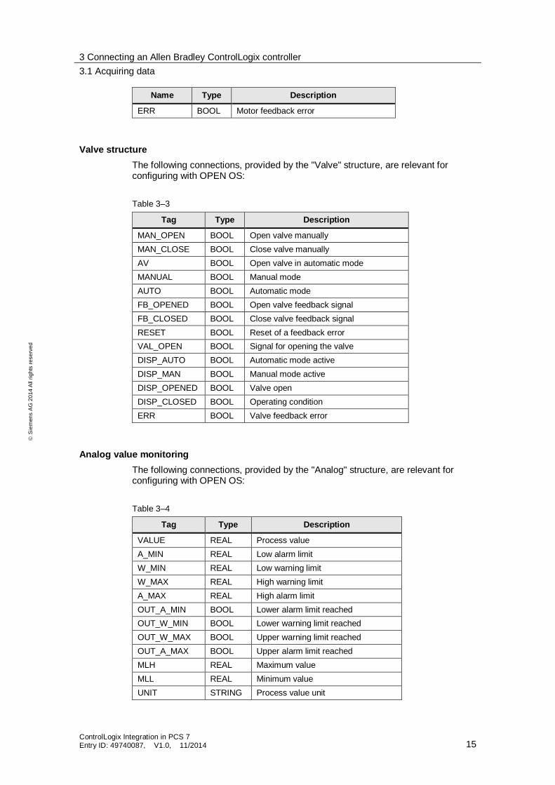
Valve structure
The following connections, provided by the "Valve" structure, are relevant for configuring with OPEN OS:
Table 3–3
Tag Type Description
MAN_OPEN BOOL Open valve manually
MAN_CLOSE BOOL Close valve manually
AV BOOL Open valve in automatic mode
MANUAL BOOL Manual mode
AUTO BOOL Automatic mode
FB_OPENED BOOL Open valve feedback signal
FB_CLOSED BOOL Close valve feedback signal
RESET BOOL Reset of a feedback error
VAL_OPEN BOOL Signal for opening the valve
DISP_AUTO BOOL Automatic mode active
DISP_MAN BOOL Manual mode active
DISP_OPENED BOOL Valve open
DISP_CLOSED BOOL Operating condition
ERR BOOL Valve feedback error
Analog value monitoring
The following connections, provided by the "Analog" structure, are relevant for configuring with OPEN OS:
Table 3–4
Tag Type Description
VALUE REAL Process value
A_MIN REAL Low alarm limit
W_MIN REAL Low warning limit
W_MAX REAL High warning limit
A_MAX REAL High alarm limit
OUT_A_MIN BOOL Lower alarm limit reached
OUT_W_MIN BOOL Lower warning limit reached
OUT_W_MAX BOOL Upper warning limit reached
OUT_A_MAX BOOL Upper alarm limit reached
MLH REAL Maximum value
MLL REAL Minimum value
UNIT STRING Process value unit
3 Connecting an Allen Bradley ControlLogix controller
3.2 Generating OS block icons and faceplates
ControlLogix Integration in PCS 7 Entry ID: 49740087, V1.0, 11/2014 16
S
iem
en
s A
G 2
01
4 A
ll ri
gh
ts r
ese
rve
d
Simulated operation
The following connections, provided by the "SimCtrl" structure, are relevant for configuring with OPEN OS:
Table 3–5
Tag Type Description
RUN BOOL 0: Stop, 1: Start
RESET BOOL Simulation is reset
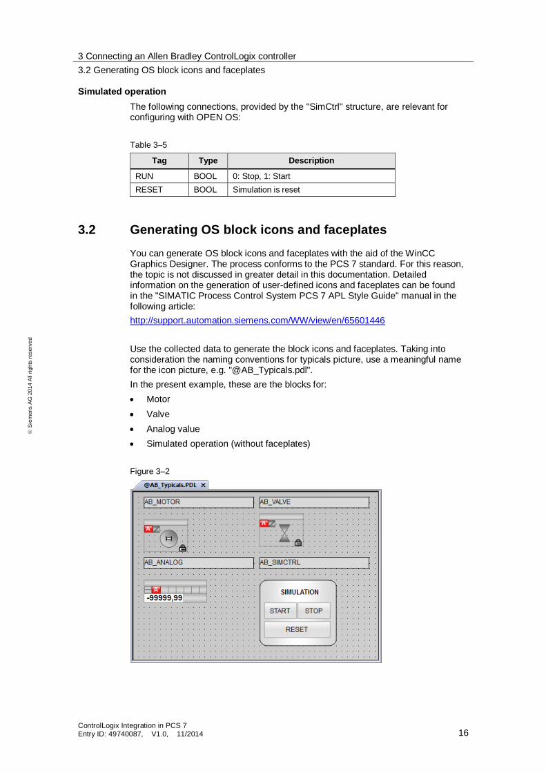
3.2 Generating OS block icons and faceplates
You can generate OS block icons and faceplates with the aid of the WinCC Graphics Designer. The process conforms to the PCS 7 standard. For this reason, the topic is not discussed in greater detail in this documentation. Detailed information on the generation of user-defined icons and faceplates can be found in the "SIMATIC Process Control System PCS 7 APL Style Guide" manual in the following article:
http://support.automation.siemens.com/WW/view/en/65601446
Use the collected data to generate the block icons and faceplates. Taking into consideration the naming conventions for typicals picture, use a meaningful name for the icon picture, e.g. "@AB_Typicals.pdl".
In the present example, these are the blocks for:
Motor
Valve
Analog value
Simulated operation (without faceplates)
Figure 3–2
3 Connecting an Allen Bradley ControlLogix controller
3.2 Generating OS block icons and faceplates
ControlLogix Integration in PCS 7 Entry ID: 49740087, V1.0, 11/2014 17
S
iem
en
s A
G 2
01
4 A
ll ri
gh
ts r
ese
rve
d
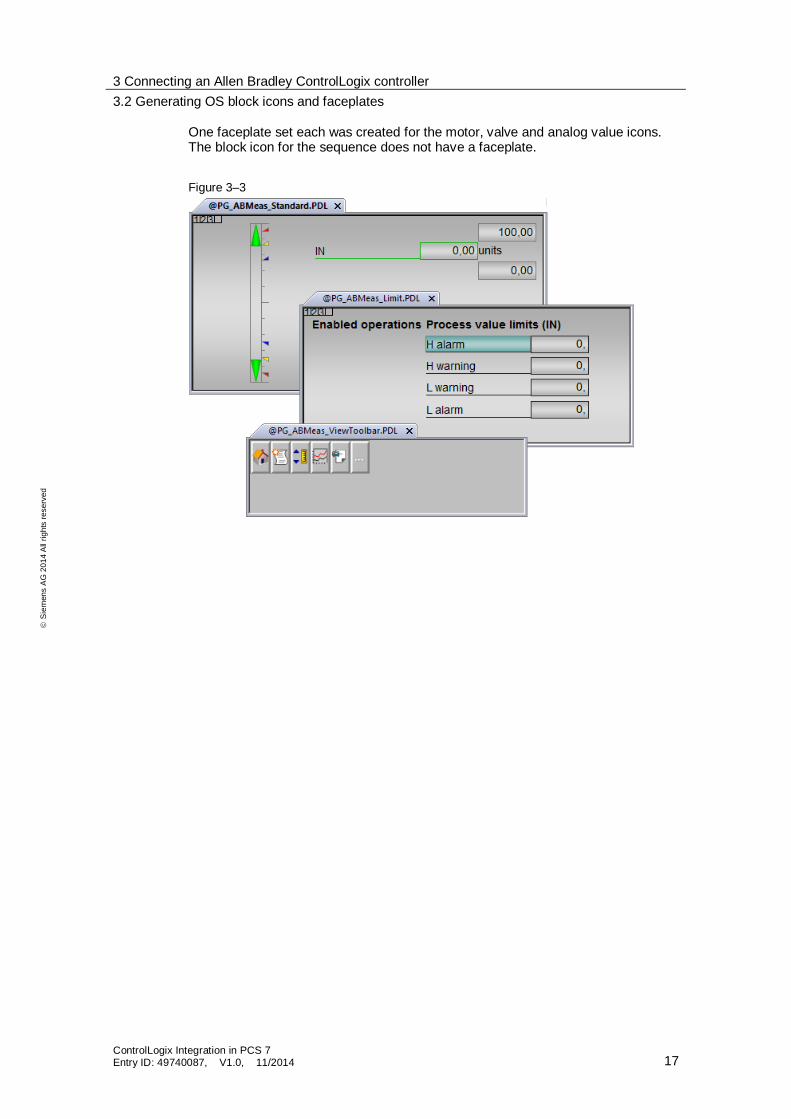
One faceplate set each was created for the motor, valve and analog value icons. The block icon for the sequence does not have a faceplate.
Figure 3–3
3 Connecting an Allen Bradley ControlLogix controller
3.3 Generating the AS node with the AS Node Type Wizard
ControlLogix Integration in PCS 7 Entry ID: 49740087, V1.0, 11/2014 18
S
iem
en
s A
G 2
01
4 A
ll ri
gh
ts r
ese
rve
d
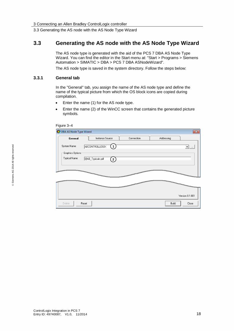
3.3 Generating the AS node with the AS Node Type Wizard
The AS node type is generated with the aid of the PCS 7 DBA AS Node Type Wizard. You can find the editor in the Start menu at: "Start > Programs > Siemens Automation > SIMATIC > DBA > PCS 7 DBA ASNodeWizard".
The AS node type is saved in the system directory. Follow the steps below:
3.3.1 General tab
In the "General" tab, you assign the name of the AS node type and define the name of the typical picture from which the OS block icons are copied during compilation.
Enter the name (1) for the AS node type.
Enter the name (2) of the WinCC screen that contains the generated picture symbols.
Figure 3–4
1
2
3 Connecting an Allen Bradley ControlLogix controller
3.3 Generating the AS node with the AS Node Type Wizard
ControlLogix Integration in PCS 7 Entry ID: 49740087, V1.0, 11/2014 19
S
iem
en
s A
G 2
01
4 A
ll ri
gh
ts r
ese
rve
d
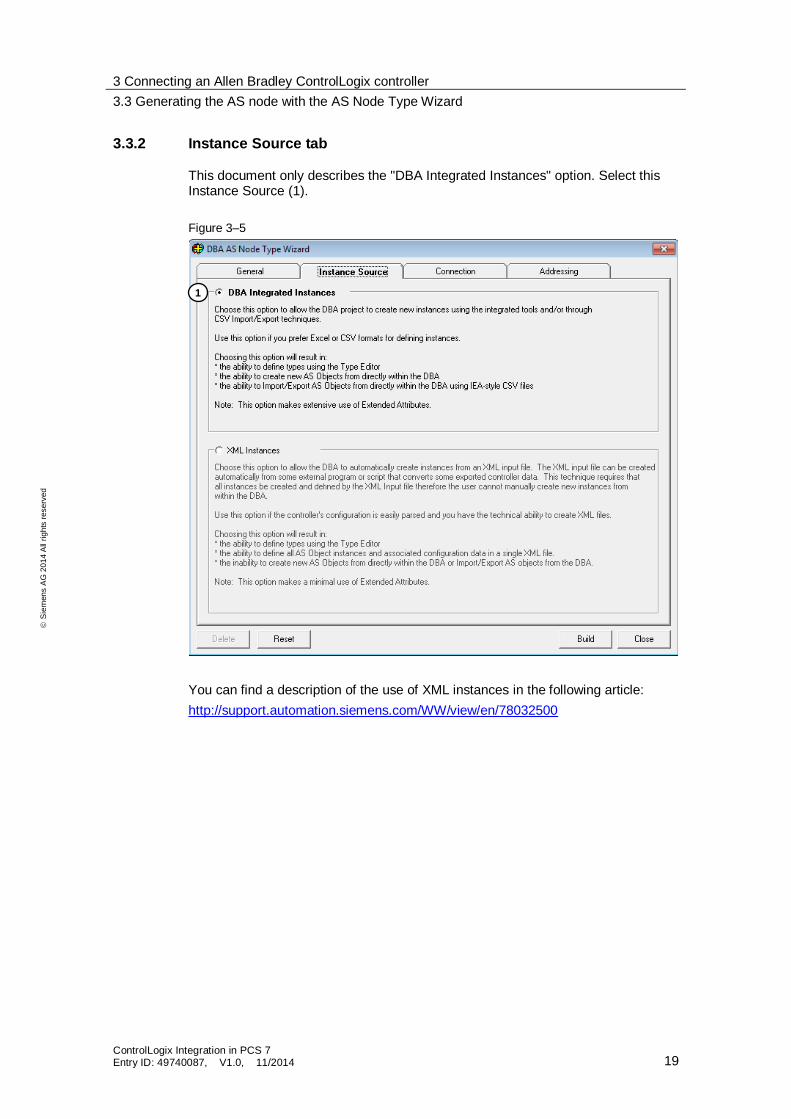
3.3.2 Instance Source tab
This document only describes the "DBA Integrated Instances" option. Select this Instance Source (1).
Figure 3–5
You can find a description of the use of XML instances in the following article:
http://support.automation.siemens.com/WW/view/en/78032500
1
3 Connecting an Allen Bradley ControlLogix controller
3.3 Generating the AS node with the AS Node Type Wizard
ControlLogix Integration in PCS 7 Entry ID: 49740087, V1.0, 11/2014 20
S
iem
en
s A
G 2
01
4 A
ll ri
gh
ts r
ese
rve
d
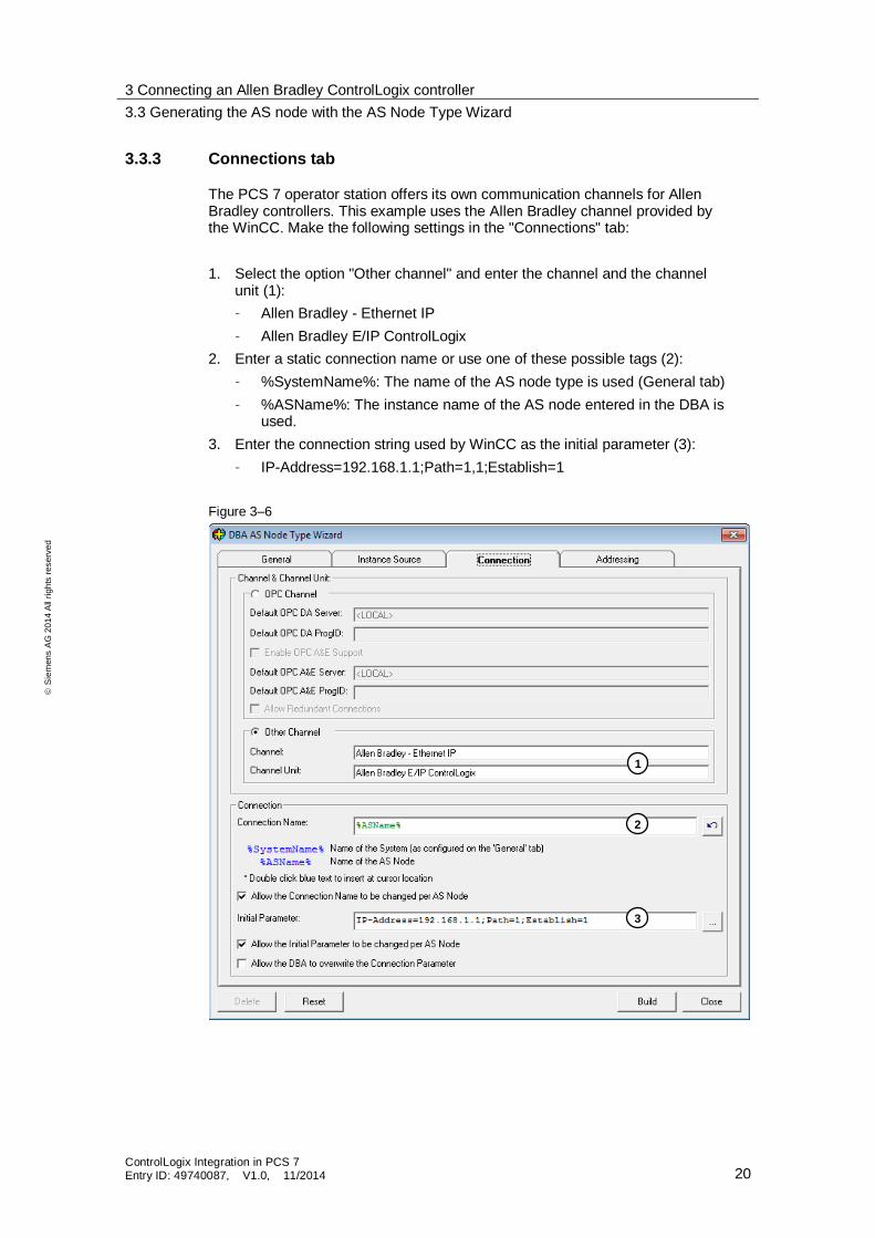
3.3.3 Connections tab
The PCS 7 operator station offers its own communication channels for Allen Bradley controllers. This example uses the Allen Bradley channel provided by the WinCC. Make the following settings in the "Connections" tab:
1. Select the option "Other channel" and enter the channel and the channel unit (1):
– Allen Bradley - Ethernet IP
– Allen Bradley E/IP ControlLogix
2. Enter a static connection name or use one of these possible tags (2):
– %SystemName%: The name of the AS node type is used (General tab)
– %ASName%: The instance name of the AS node entered in the DBA is used.
3. Enter the connection string used by WinCC as the initial parameter (3):
– IP-Address=192.168.1.1;Path=1,1;Establish=1
Figure 3–6
1
2
3
3 Connecting an Allen Bradley ControlLogix controller
3.3 Generating the AS node with the AS Node Type Wizard
ControlLogix Integration in PCS 7 Entry ID: 49740087, V1.0, 11/2014 21
S
iem
en
s A
G 2
01
4 A
ll ri
gh
ts r
ese
rve
d
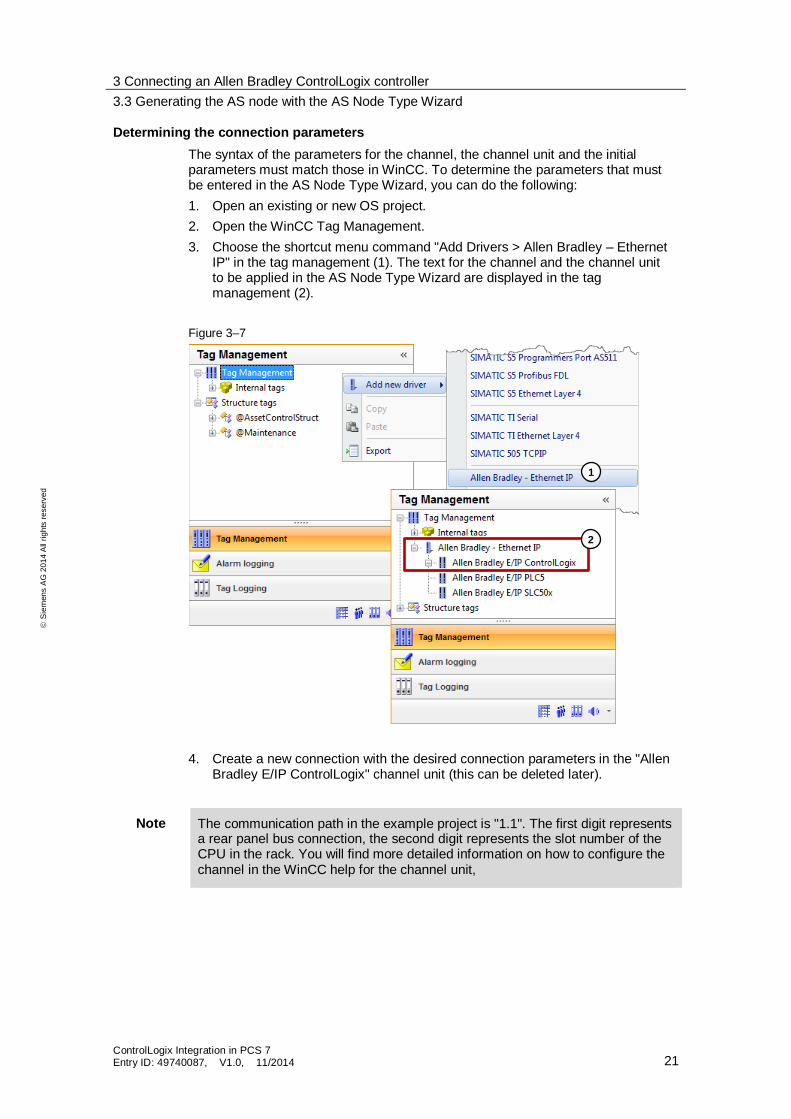
Determining the connection parameters
The syntax of the parameters for the channel, the channel unit and the initial parameters must match those in WinCC. To determine the parameters that must be entered in the AS Node Type Wizard, you can do the following:
1. Open an existing or new OS project.
2. Open the WinCC Tag Management.
3. Choose the shortcut menu command "Add Drivers > Allen Bradley – Ethernet IP" in the tag management (1). The text for the channel and the channel unit to be applied in the AS Node Type Wizard are displayed in the tag management (2).
Figure 3–7
4. Create a new connection with the desired connection parameters in the "Allen Bradley E/IP ControlLogix" channel unit (this can be deleted later).
Note The communication path in the example project is "1.1". The first digit represents a rear panel bus connection, the second digit represents the slot number of the CPU in the rack. You will find more detailed information on how to configure the channel in the WinCC help for the channel unit,
1
2
3 Connecting an Allen Bradley ControlLogix controller
3.3 Generating the AS node with the AS Node Type Wizard
ControlLogix Integration in PCS 7 Entry ID: 49740087, V1.0, 11/2014 22
S
iem
en
s A
G 2
01
4 A
ll ri
gh
ts r
ese
rve
d
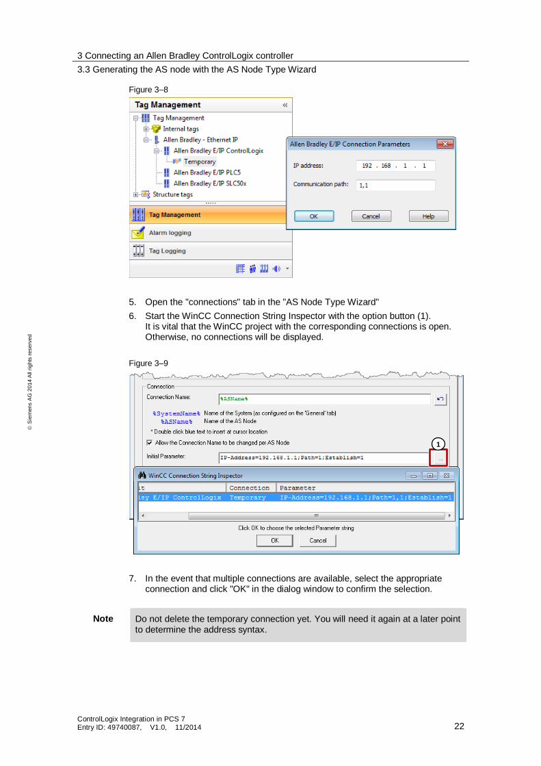
Figure 3–8
5. Open the "connections" tab in the "AS Node Type Wizard"
6. Start the WinCC Connection String Inspector with the option button (1). It is vital that the WinCC project with the corresponding connections is open. Otherwise, no connections will be displayed.
Figure 3–9
7. In the event that multiple connections are available, select the appropriate connection and click "OK" in the dialog window to confirm the selection.
Note Do not delete the temporary connection yet. You will need it again at a later point to determine the address syntax.
1
3 Connecting an Allen Bradley ControlLogix controller
3.3 Generating the AS node with the AS Node Type Wizard
ControlLogix Integration in PCS 7 Entry ID: 49740087, V1.0, 11/2014 23
S
iem
en
s A
G 2
01
4 A
ll ri
gh
ts r
ese
rve
d
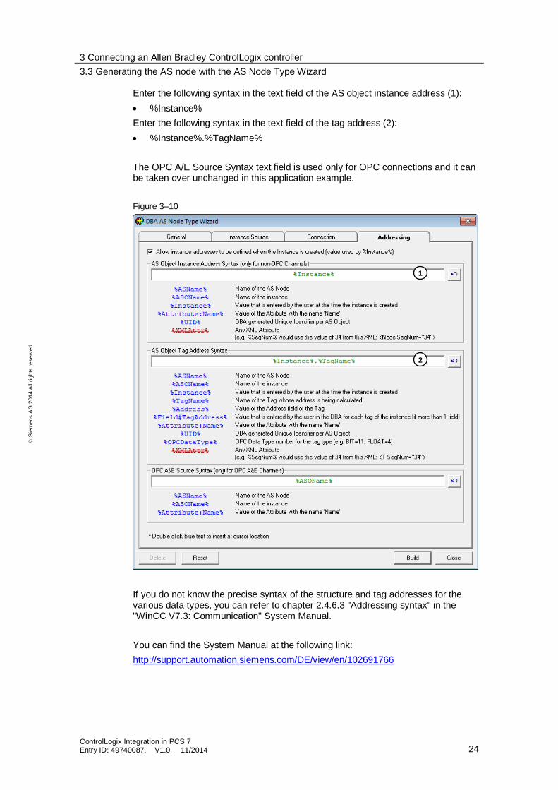
3.3.4 Addressing tab
In the Addressing tab, you can specify the structure of the AS and tag addressing that will be used when the project is compiled at a later point. The address structure depends on the communications driver that is set. Here, the DBA offers the option of assigning parameters for all conceivable constellations. These range from a structured approach and the free assignment of addresses for all tags to the use of scripts that can calculate the addresses individually.
The following tags are available for the assignment of ASO address parameters:
%ASName% – name of the AS type
%ASOName% – name of the AS instance
%Instance% – assigned during instantiation
%Attribute:Name% – value of the specified attribute
%UID% – unique identifier generated by the DBA
The following tags are available for the assignment of tag address parameters:
%ASName% – name of the AS type
%ASOName% – name of the AS instance
%Instance% – assigned during instantiation
%Tagname% – name of the tags for which the address is calculated
%Address% – value of the address field of the tags
%Field#TagAddress% – value of the extended attribute. Input during parameter assignment
%Attribute:Name% – value of the extended attribute with the name "Name"
%UID% – unique identifier generated by the DBA
%OPCDataType% – OPC data type number for the tag type
In this example, the program of the Allen Bradley controller is designed in a structured manner. Recurring features were derived or instantiated from a structure type. Instances of the same structure type are always built identically. When configuring the PCS 7 operator station, the names chosen for the instances were the same as the name of the instances in Studio 5000 Logix Designer.
The address of an attribute within a structure is composed of the name of an instance of the same structure and the name of the structure attribute. They are both separated by a period.
Example:
Structure name: AB_MOTOR
Attribute: MOT_ON
Structure instance: MOT1 (type AB_MOTOR)
Attribute address: MOT1.MOT_ON
3 Connecting an Allen Bradley ControlLogix controller
3.3 Generating the AS node with the AS Node Type Wizard
ControlLogix Integration in PCS 7 Entry ID: 49740087, V1.0, 11/2014 24
S
iem
en
s A
G 2
01
4 A
ll ri
gh
ts r
ese
rve
d
Enter the following syntax in the text field of the AS object instance address (1):
%Instance%
Enter the following syntax in the text field of the tag address (2):
%Instance%.%TagName%
The OPC A/E Source Syntax text field is used only for OPC connections and it can be taken over unchanged in this application example.
Figure 3–10
If you do not know the precise syntax of the structure and tag addresses for the various data types, you can refer to chapter 2.4.6.3 "Addressing syntax" in the "WinCC V7.3: Communication" System Manual.
You can find the System Manual at the following link:
http://support.automation.siemens.com/DE/view/en/102691766
1
2
3 Connecting an Allen Bradley ControlLogix controller
3.4 Creating the AS node
ControlLogix Integration in PCS 7 Entry ID: 49740087, V1.0, 11/2014 25
S
iem
en
s A
G 2
01
4 A
ll ri
gh
ts r
ese
rve
d
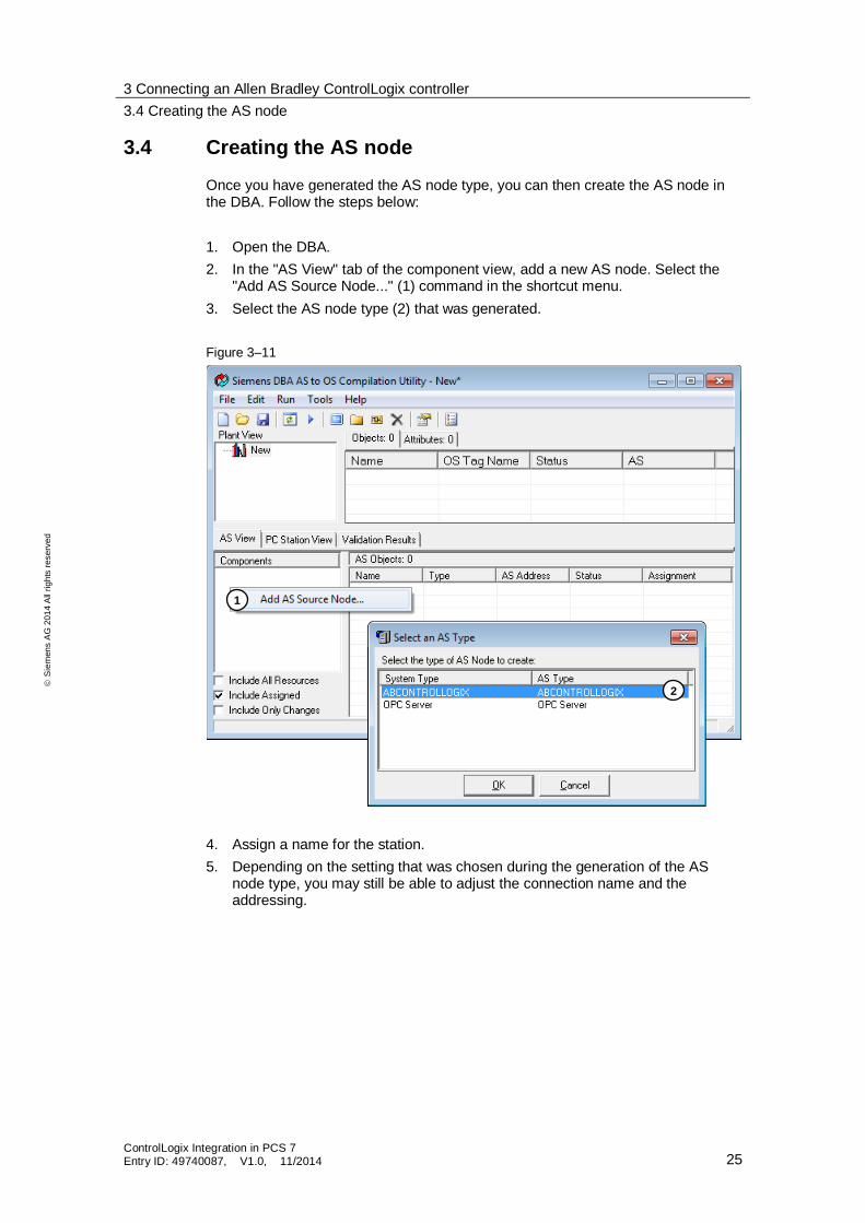
3.4 Creating the AS node
Once you have generated the AS node type, you can then create the AS node in the DBA. Follow the steps below:
1. Open the DBA.
2. In the "AS View" tab of the component view, add a new AS node. Select the "Add AS Source Node..." (1) command in the shortcut menu.
3. Select the AS node type (2) that was generated.
Figure 3–11
4. Assign a name for the station.
5. Depending on the setting that was chosen during the generation of the AS node type, you may still be able to adjust the connection name and the addressing.
1
2
3 Connecting an Allen Bradley ControlLogix controller
3.4 Creating the AS node
ControlLogix Integration in PCS 7 Entry ID: 49740087, V1.0, 11/2014 26
S
iem
en
s A
G 2
01
4 A
ll ri
gh
ts r
ese
rve
d
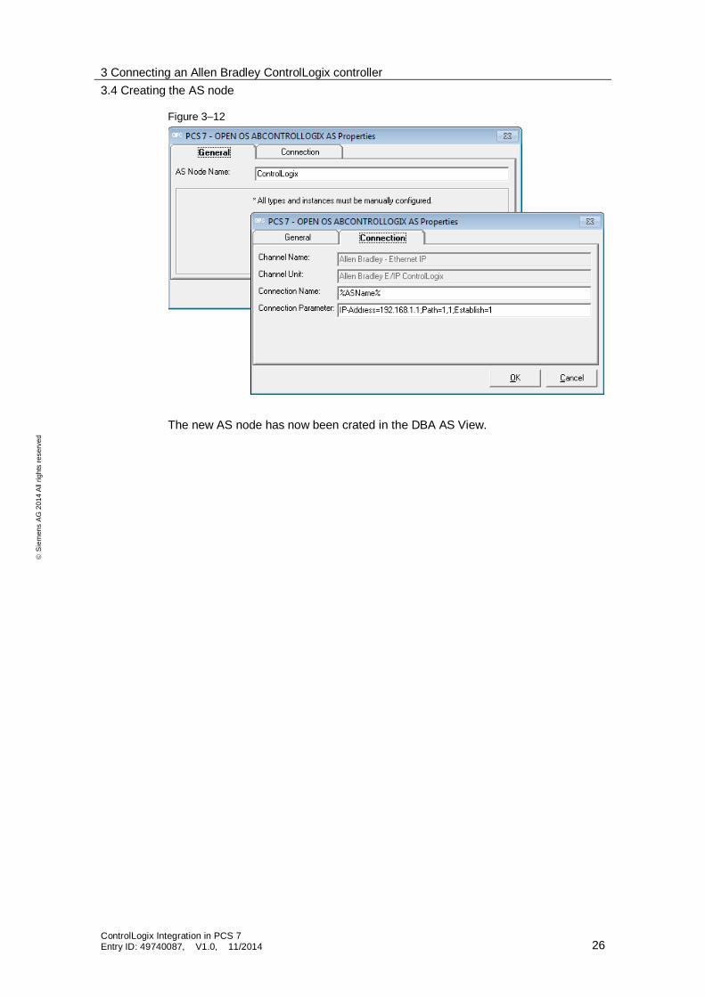
Figure 3–12
The new AS node has now been crated in the DBA AS View.
3 Connecting an Allen Bradley ControlLogix controller
3.5 Generating AS object types
ControlLogix Integration in PCS 7 Entry ID: 49740087, V1.0, 11/2014 27
S
iem
en
s A
G 2
01
4 A
ll ri
gh
ts r
ese
rve
d
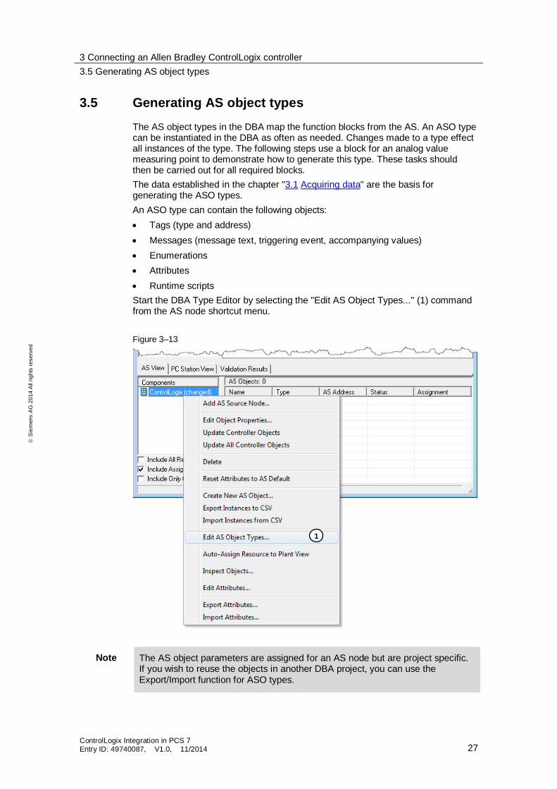
3.5 Generating AS object types
The AS object types in the DBA map the function blocks from the AS. An ASO type can be instantiated in the DBA as often as needed. Changes made to a type effect all instances of the type. The following steps use a block for an analog value measuring point to demonstrate how to generate this type. These tasks should then be carried out for all required blocks.
The data established in the chapter "3.1 Acquiring data" are the basis for generating the ASO types.
An ASO type can contain the following objects:
Tags (type and address)
Messages (message text, triggering event, accompanying values)
Enumerations
Attributes
Runtime scripts
Start the DBA Type Editor by selecting the "Edit AS Object Types..." (1) command from the AS node shortcut menu.
Figure 3–13
Note The AS object parameters are assigned for an AS node but are project specific. If you wish to reuse the objects in another DBA project, you can use the Export/Import function for ASO types.
1
3 Connecting an Allen Bradley ControlLogix controller
3.5 Generating AS object types
ControlLogix Integration in PCS 7 Entry ID: 49740087, V1.0, 11/2014 28
S
iem
en
s A
G 2
01
4 A
ll ri
gh
ts r
ese
rve
d
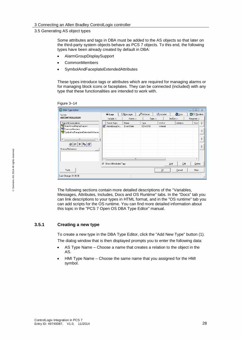
Some attributes and tags in DBA must be added to the AS objects so that later on the third-party system objects behave as PCS 7 objects. To this end, the following types have been already created by default in DBA:
AlarmGroupDisplaySupport
CommonMembers
SymbolAndFaceplateExtendedAttributes
These types introduce tags or attributes which are required for managing alarms or for managing block icons or faceplates. They can be connected (included) with any type that these functionalities are intended to work with.
Figure 3–14
The following sections contain more detailed descriptions of the "Variables, Messages, Attributes, Includes, Docs and OS Runtime" tabs. In the "Docs" tab you can link descriptions to your types in HTML format, and in the "OS runtime" tab you can add scripts for the OS runtime. You can find more detailed information about this topic in the "PCS 7 Open OS DBA Type Editor" manual.
3.5.1 Creating a new type
To create a new type in the DBA Type Editor, click the "Add New Type" button (1).
The dialog window that is then displayed prompts you to enter the following data:
AS Type Name – Choose a name that creates a relation to the object in the AS.
HMI Type Name – Choose the same name that you assigned for the HMI symbol.
3 Connecting an Allen Bradley ControlLogix controller
3.5 Generating AS object types
ControlLogix Integration in PCS 7 Entry ID: 49740087, V1.0, 11/2014 29
S
iem
en
s A
G 2
01
4 A
ll ri
gh
ts r
ese
rve
d
Figure 3–15
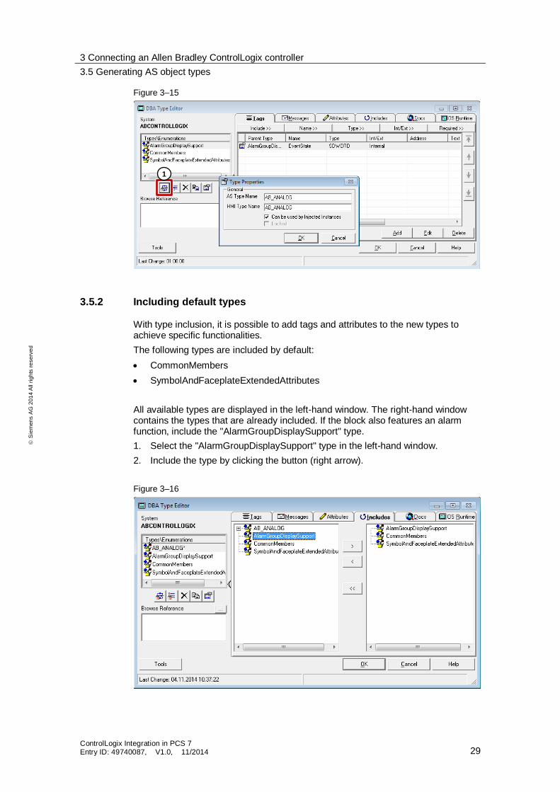
3.5.2 Including default types
With type inclusion, it is possible to add tags and attributes to the new types to achieve specific functionalities.
The following types are included by default:
CommonMembers
SymbolAndFaceplateExtendedAttributes
All available types are displayed in the left-hand window. The right-hand window contains the types that are already included. If the block also features an alarm function, include the "AlarmGroupDisplaySupport" type.
1. Select the "AlarmGroupDisplaySupport" type in the left-hand window.
2. Include the type by clicking the button (right arrow).
Figure 3–16
1
3 Connecting an Allen Bradley ControlLogix controller
3.5 Generating AS object types
ControlLogix Integration in PCS 7 Entry ID: 49740087, V1.0, 11/2014 30
S
iem
en
s A
G 2
01
4 A
ll ri
gh
ts r
ese
rve
d
The new type is now equipped with the basic functionality for PCS 7 blocks. You can remove the functionality of the included types by clicking the "Left arrow" button.
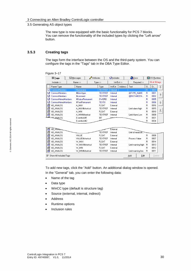
3.5.3 Creating tags
The tags form the interface between the OS and the third-party system. You can configure the tags in the "Tags" tab in the DBA Type Editor.
Figure 3–17
To add new tags, click the "Add" button. An additional dialog window is opened.
In the "General" tab, you can enter the following data:
Name of the tag
Data type
WinCC type (default is structure tag)
Source (external, internal, indirect)
Address
Runtime options
Inclusion rules
3 Connecting an Allen Bradley ControlLogix controller
3.5 Generating AS object types
ControlLogix Integration in PCS 7 Entry ID: 49740087, V1.0, 11/2014 31
S
iem
en
s A
G 2
01
4 A
ll ri
gh
ts r
ese
rve
d
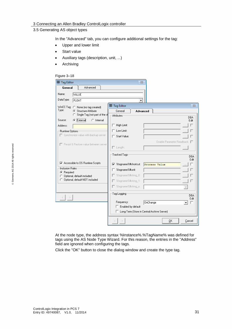
In the "Advanced" tab, you can configure additional settings for the tag:
Upper and lower limit
Start value
Auxiliary tags (description, unit, ...)
Archiving
Figure 3–18
At the node type, the address syntax %Instance%.%TagName% was defined for tags using the AS Node Type Wizard. For this reason, the entries in the "Address" field are ignored when configuring the tags.
Click the "OK" button to close the dialog window and create the type tag.
3 Connecting an Allen Bradley ControlLogix controller
3.5 Generating AS object types
ControlLogix Integration in PCS 7 Entry ID: 49740087, V1.0, 11/2014 32
S
iem
en
s A
G 2
01
4 A
ll ri
gh
ts r
ese
rve
d
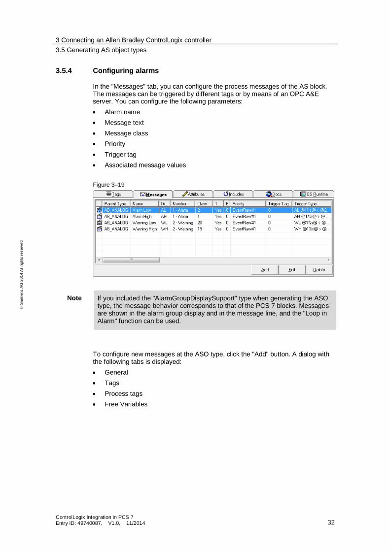
3.5.4 Configuring alarms
In the "Messages" tab, you can configure the process messages of the AS block. The messages can be triggered by different tags or by means of an OPC A&E server. You can configure the following parameters:
Alarm name
Message text
Message class
Priority
Trigger tag
Associated message values
Figure 3–19
Note If you included the "AlarmGroupDisplaySupport" type when generating the ASO type, the message behavior corresponds to that of the PCS 7 blocks. Messages are shown in the alarm group display and in the message line, and the "Loop in Alarm" function can be used.
To configure new messages at the ASO type, click the "Add" button. A dialog with the following tabs is displayed:
General
Tags
Process tags
Free Variables
3 Connecting an Allen Bradley ControlLogix controller
3.5 Generating AS object types
ControlLogix Integration in PCS 7 Entry ID: 49740087, V1.0, 11/2014 33
S
iem
en
s A
G 2
01
4 A
ll ri
gh
ts r
ese
rve
d
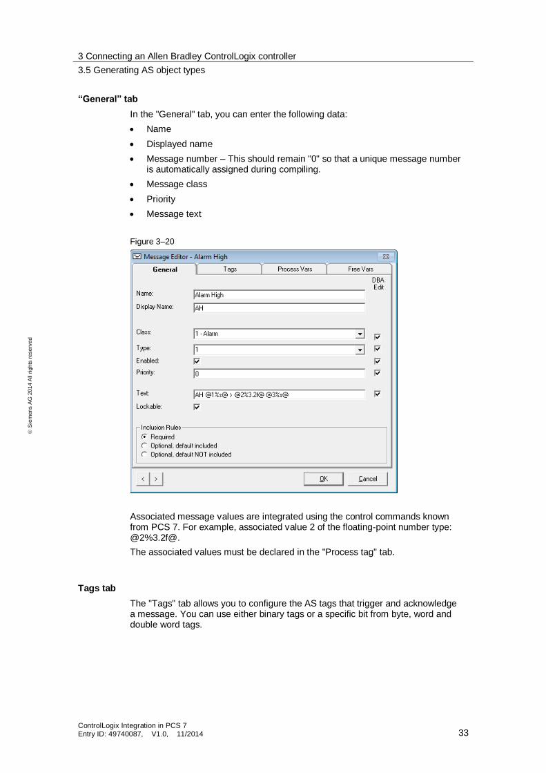
“General” tab
In the "General" tab, you can enter the following data:
Name
Displayed name
Message number – This should remain "0" so that a unique message number is automatically assigned during compiling.
Message class
Priority
Message text
Figure 3–20
Associated message values are integrated using the control commands known from PCS 7. For example, associated value 2 of the floating-point number type: @2%3.2f@.
The associated values must be declared in the "Process tag" tab.
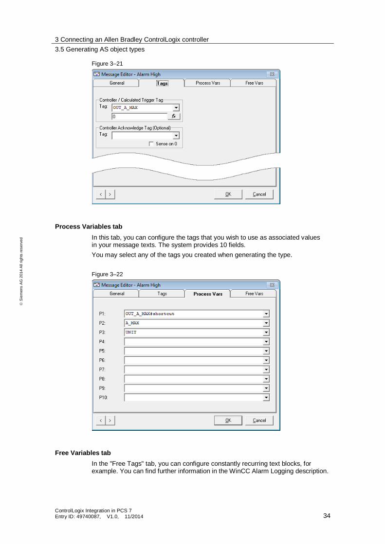
Tags tab
The "Tags" tab allows you to configure the AS tags that trigger and acknowledge a message. You can use either binary tags or a specific bit from byte, word and double word tags.
3 Connecting an Allen Bradley ControlLogix controller
3.5 Generating AS object types
ControlLogix Integration in PCS 7 Entry ID: 49740087, V1.0, 11/2014 34
S
iem
en
s A
G 2
01
4 A
ll ri
gh
ts r
ese
rve
d
Figure 3–21
Process Variables tab
In this tab, you can configure the tags that you wish to use as associated values in your message texts. The system provides 10 fields.
You may select any of the tags you created when generating the type.
Figure 3–22
Free Variables tab
In the "Free Tags" tab, you can configure constantly recurring text blocks, for example. You can find further information in the WinCC Alarm Logging description.
3 Connecting an Allen Bradley ControlLogix controller
3.5 Generating AS object types
ControlLogix Integration in PCS 7 Entry ID: 49740087, V1.0, 11/2014 35
S
iem
en
s A
G 2
01
4 A
ll ri
gh
ts r
ese
rve
d
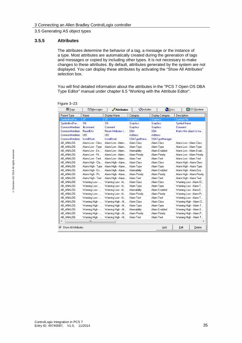
3.5.5 Attributes
The attributes determine the behavior of a tag, a message or the instance of a type. Most attributes are automatically created during the generation of tags and messages or copied by including other types. It is not necessary to make changes to these attributes. By default, attributes generated by the system are not displayed. You can display these attributes by activating the "Show All Attributes" selection box.
You will find detailed information about the attributes in the "PCS 7 Open OS DBA Type Editor" manual under chapter 6.5 "Working with the Attribute Editor".
Figure 3–23
3 Connecting an Allen Bradley ControlLogix controller
3.6 Creating ASO instances
ControlLogix Integration in PCS 7 Entry ID: 49740087, V1.0, 11/2014 36
S
iem
en
s A
G 2
01
4 A
ll ri
gh
ts r
ese
rve
d
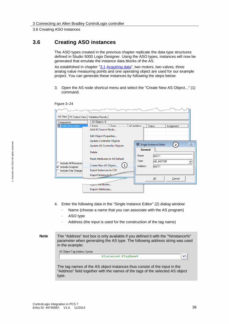
3.6 Creating ASO instances
The ASO types created in the previous chapter replicate the data type structures defined in Studio 5000 Logix Designer. Using the ASO types, instances will now be generated that emulate the instance data blocks of the AS.
As established in chapter "3.1 Acquiring data", two motors, two valves, three analog value measuring points and one operating object are used for our example project. You can generate these instances by following the steps below:
3. Open the AS node shortcut menu and select the "Create New AS Object..." (1) command.
Figure 3–24
4. Enter the following data in the "Single Instance Editor" (2) dialog window:
– Name (choose a name that you can associate with the AS program)
– ASO type
– Address (the input is used for the construction of the tag name)
Note The "Address" text box is only available if you defined it with the "%Instance%" parameter when generating the AS type. The following address string was used in the example:
The tag names of the AS object instances thus consist of the input in the "Address" field together with the names of the tags of the selected AS object type.
1
2
3 Connecting an Allen Bradley ControlLogix controller
3.6 Creating ASO instances
ControlLogix Integration in PCS 7 Entry ID: 49740087, V1.0, 11/2014 37
S
iem
en
s A
G 2
01
4 A
ll ri
gh
ts r
ese
rve
d
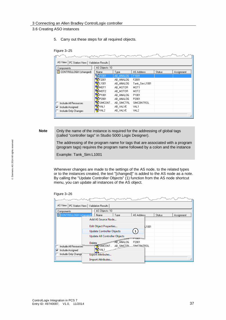
5. Carry out these steps for all required objects.
Figure 3–25
Note Only the name of the instance is required for the addressing of global tags (called "controller tags" in Studio 5000 Logix Designer).
The addressing of the program name for tags that are associated with a program (program tags) requires the program name followed by a colon and the instance
Example: Tank_Sim:L1001
Whenever changes are made to the settings of the AS node, to the related types or to the instances created, the text "[changed]" is added to the AS node as a note. By calling the "Update Controller Objects" (1) function from the AS node shortcut menu, you can update all instances of the AS object.
Figure 3–26
1
3 Connecting an Allen Bradley ControlLogix controller
3.6 Creating ASO instances
ControlLogix Integration in PCS 7 Entry ID: 49740087, V1.0, 11/2014 38
S
iem
en
s A
G 2
01
4 A
ll ri
gh
ts r
ese
rve
d
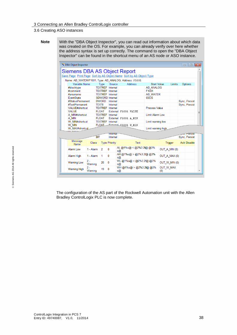
Note With the "DBA Object Inspector", you can read out information about which data was created on the OS. For example, you can already verify over here whether the address syntax is set up correctly. The command to open the "DBA Object Inspector" can be found in the shortcut menu of an AS node or ASO instance.
The configuration of the AS part of the Rockwell Automation unit with the Allen Bradley ControlLogix PLC is now complete.
4 Configuring the PC station with the DBA
4.1 Adding a PC Station
ControlLogix Integration in PCS 7 Entry ID: 49740087, V1.0, 11/2014 39
S
iem
en
s A
G 2
01
4 A
ll ri
gh
ts r
ese
rve
d
4 Configuring the PC station with the DBA The PC station in the DBA Editor serves as an interface to the operator system on which the third-party system is operated and monitored.
To create a PC station in the DBA, you first need a PCS 7 project complete with an operator station and a plant hierarchy. This can be a finished project that is to be expanded to include the functionality of the package unit, or a newly created project.
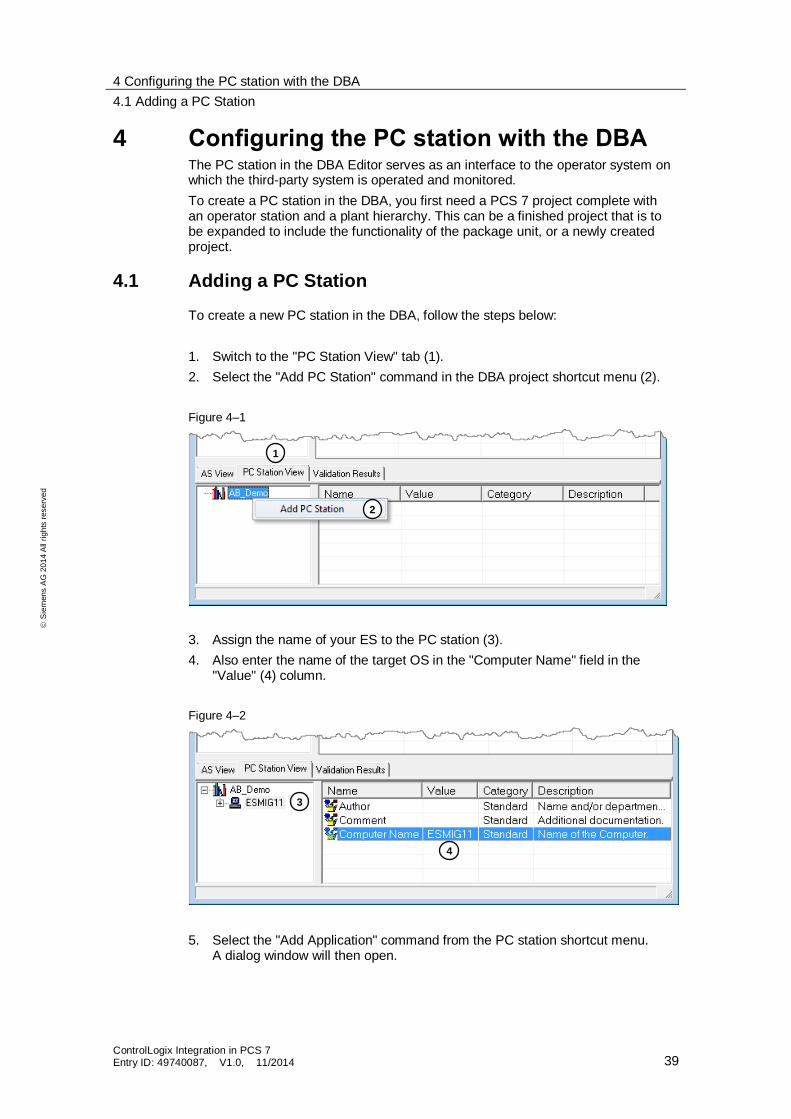
4.1 Adding a PC Station
To create a new PC station in the DBA, follow the steps below:
1. Switch to the "PC Station View" tab (1).
2. Select the "Add PC Station" command in the DBA project shortcut menu (2).
Figure 4–1
3. Assign the name of your ES to the PC station (3).
4. Also enter the name of the target OS in the "Computer Name" field in the "Value" (4) column.
Figure 4–2
5. Select the "Add Application" command from the PC station shortcut menu. A dialog window will then open.
1
2
4
3
4 Configuring the PC station with the DBA
4.1 Adding a PC Station
ControlLogix Integration in PCS 7 Entry ID: 49740087, V1.0, 11/2014 40
S
iem
en
s A
G 2
01
4 A
ll ri
gh
ts r
ese
rve
d
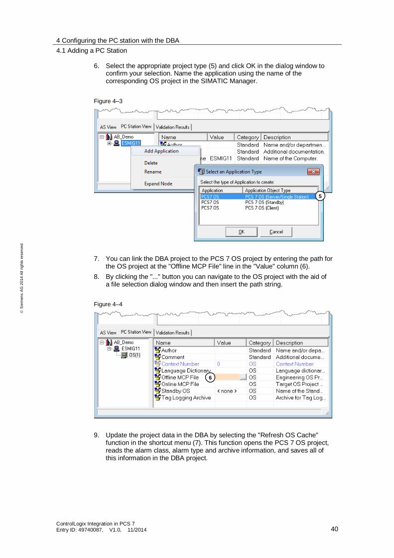
6. Select the appropriate project type (5) and click OK in the dialog window to confirm your selection. Name the application using the name of the corresponding OS project in the SIMATIC Manager.
Figure 4–3
7. You can link the DBA project to the PCS 7 OS project by entering the path for the OS project at the "Offline MCP File" line in the "Value" column (6).
8. By clicking the "..." button you can navigate to the OS project with the aid of a file selection dialog window and then insert the path string.
Figure 4–4
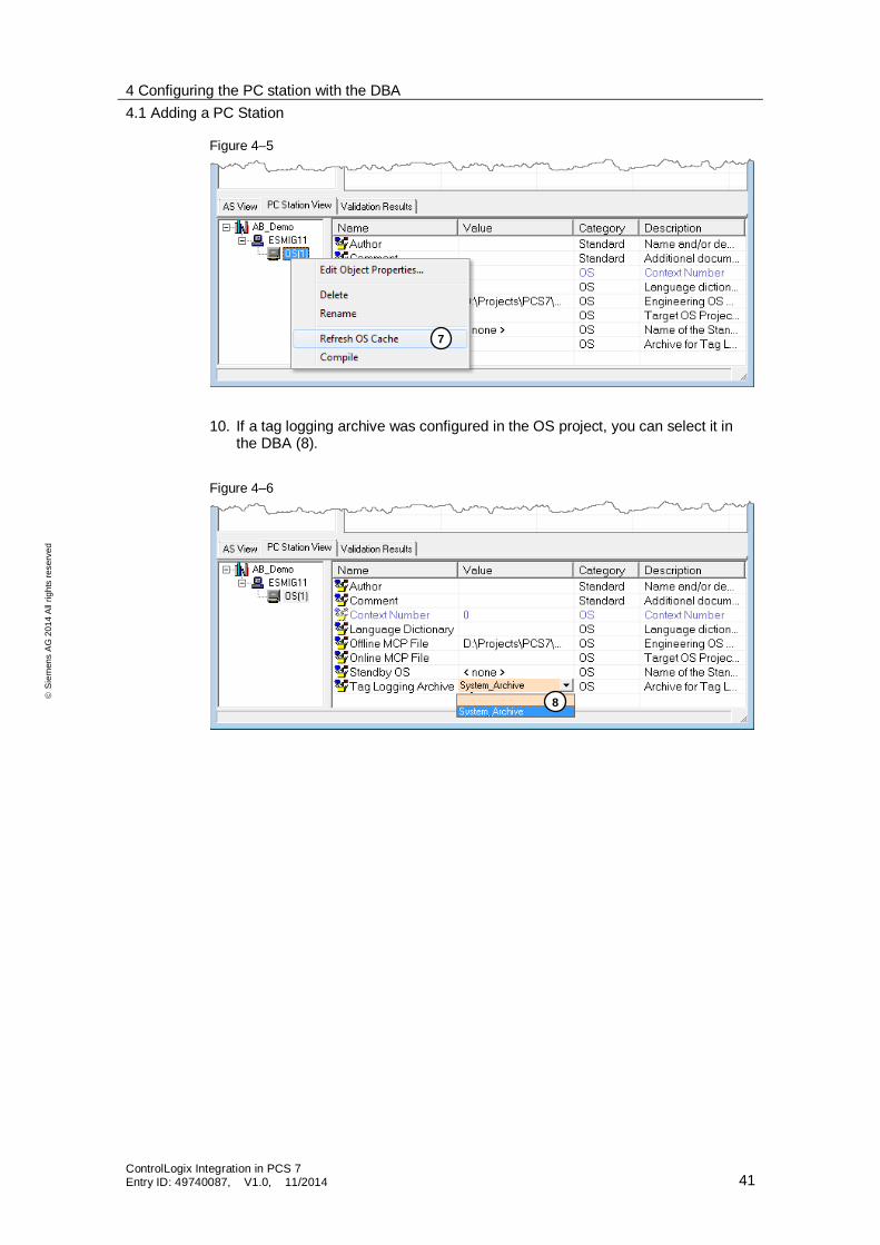
9. Update the project data in the DBA by selecting the "Refresh OS Cache" function in the shortcut menu (7). This function opens the PCS 7 OS project, reads the alarm class, alarm type and archive information, and saves all of this information in the DBA project.
5
6
4 Configuring the PC station with the DBA
4.1 Adding a PC Station
ControlLogix Integration in PCS 7 Entry ID: 49740087, V1.0, 11/2014 41
S
iem
en
s A
G 2
01
4 A
ll ri
gh
ts r
ese
rve
d
Figure 4–5
10. If a tag logging archive was configured in the OS project, you can select it in the DBA (8).
Figure 4–6
7
8
4 Configuring the PC station with the DBA
4.2 Creating a plant hierarchy
ControlLogix Integration in PCS 7 Entry ID: 49740087, V1.0, 11/2014 42
S
iem
en
s A
G 2
01
4 A
ll ri
gh
ts r
ese
rve
d
4.2 Creating a plant hierarchy
In the DBA, you can use the plant hierarchy to define the picture hierarchy as it appears on the OS. It is possible to use and extend an existing hierarchy from a PCS 7 project or to generate a new hierarchy.
You will find detailed information in the PCS 7 Open OS DBA user manual.
In this example, an existing PH will be extended.
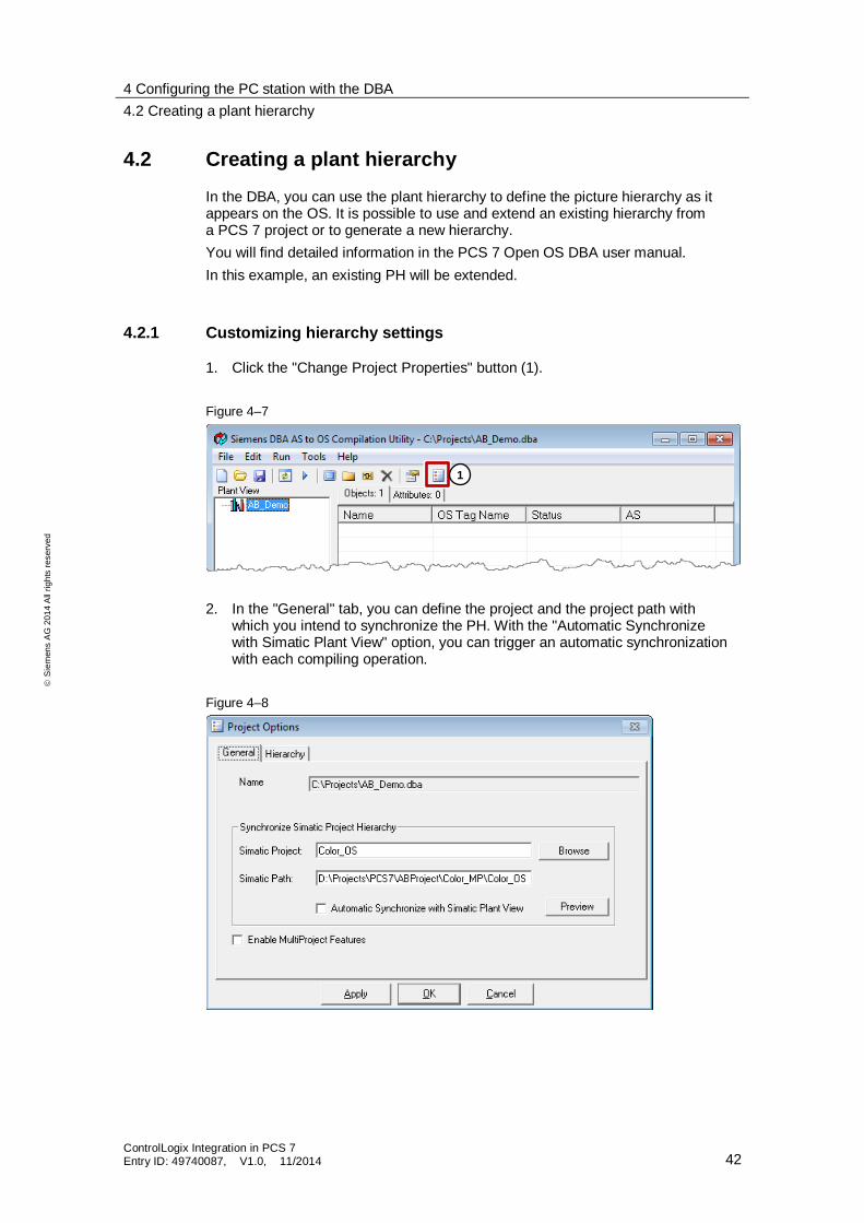
4.2.1 Customizing hierarchy settings
1. Click the "Change Project Properties" button (1).
Figure 4–7
2. In the "General" tab, you can define the project and the project path with which you intend to synchronize the PH. With the "Automatic Synchronize with Simatic Plant View" option, you can trigger an automatic synchronization with each compiling operation.
Figure 4–8
1
4 Configuring the PC station with the DBA
4.2 Creating a plant hierarchy
ControlLogix Integration in PCS 7 Entry ID: 49740087, V1.0, 11/2014 43
S
iem
en
s A
G 2
01
4 A
ll ri
gh
ts r
ese
rve
d
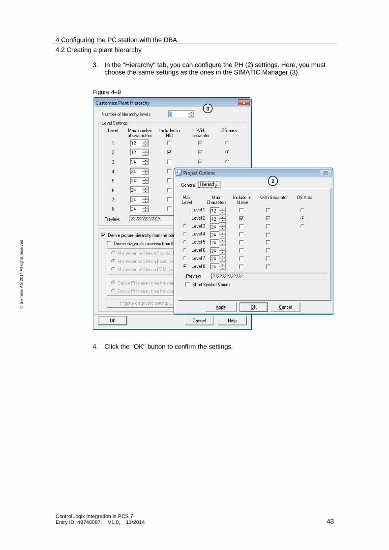
3. In the "Hierarchy" tab, you can configure the PH (2) settings. Here, you must choose the same settings as the ones in the SIMATIC Manager (3).
Figure 4–9
4. Click the "OK" button to confirm the settings.
2
3
4 Configuring the PC station with the DBA
4.2 Creating a plant hierarchy
ControlLogix Integration in PCS 7 Entry ID: 49740087, V1.0, 11/2014 44
S
iem
en
s A
G 2
01
4 A
ll ri
gh
ts r
ese
rve
d
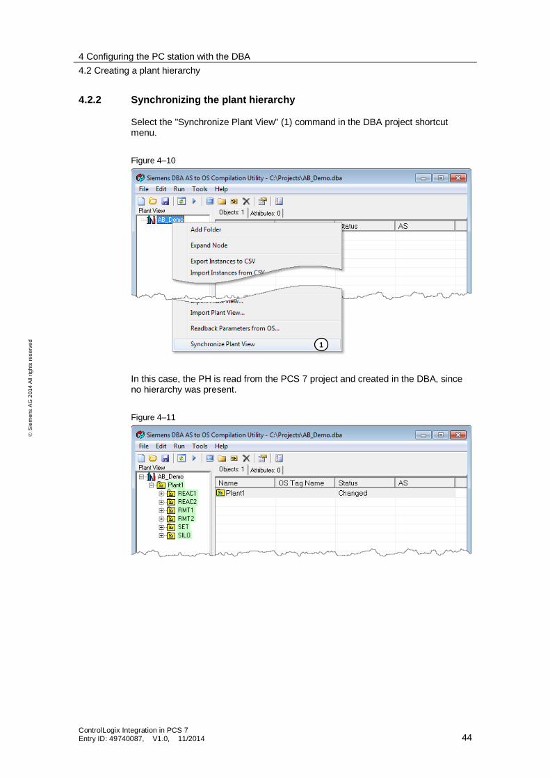
4.2.2 Synchronizing the plant hierarchy
Select the "Synchronize Plant View" (1) command in the DBA project shortcut menu.
Figure 4–10
In this case, the PH is read from the PCS 7 project and created in the DBA, since no hierarchy was present.
Figure 4–11
1
4 Configuring the PC station with the DBA
4.2 Creating a plant hierarchy
ControlLogix Integration in PCS 7 Entry ID: 49740087, V1.0, 11/2014 45
S
iem
en
s A
G 2
01
4 A
ll ri
gh
ts r
ese
rve
d
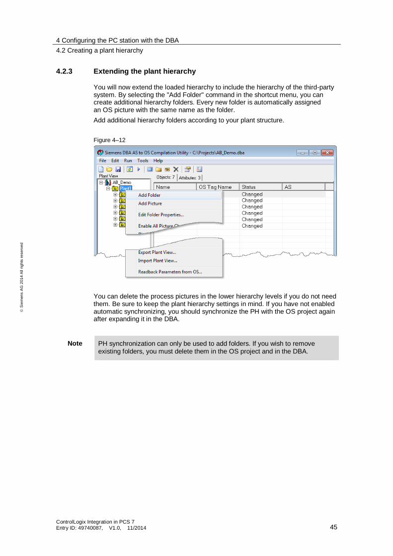
4.2.3 Extending the plant hierarchy
You will now extend the loaded hierarchy to include the hierarchy of the third-party system. By selecting the "Add Folder" command in the shortcut menu, you can create additional hierarchy folders. Every new folder is automatically assigned an OS picture with the same name as the folder.
Add additional hierarchy folders according to your plant structure.
Figure 4–12
You can delete the process pictures in the lower hierarchy levels if you do not need them. Be sure to keep the plant hierarchy settings in mind. If you have not enabled automatic synchronizing, you should synchronize the PH with the OS project again after expanding it in the DBA.
Note PH synchronization can only be used to add folders. If you wish to remove existing folders, you must delete them in the OS project and in the DBA.
4 Configuring the PC station with the DBA
4.2 Creating a plant hierarchy
ControlLogix Integration in PCS 7 Entry ID: 49740087, V1.0, 11/2014 46
S
iem
en
s A
G 2
01
4 A
ll ri
gh
ts r
ese
rve
d
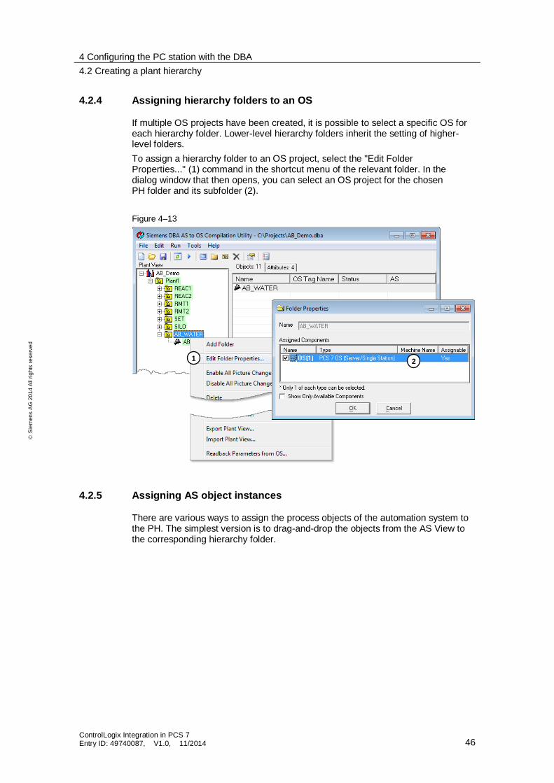
4.2.4 Assigning hierarchy folders to an OS
If multiple OS projects have been created, it is possible to select a specific OS for each hierarchy folder. Lower-level hierarchy folders inherit the setting of higher-level folders.
To assign a hierarchy folder to an OS project, select the "Edit Folder Properties..." (1) command in the shortcut menu of the relevant folder. In the dialog window that then opens, you can select an OS project for the chosen PH folder and its subfolder (2).
Figure 4–13
4.2.5 Assigning AS object instances
There are various ways to assign the process objects of the automation system to the PH. The simplest version is to drag-and-drop the objects from the AS View to the corresponding hierarchy folder.
1 2
4 Configuring the PC station with the DBA
4.2 Creating a plant hierarchy
ControlLogix Integration in PCS 7 Entry ID: 49740087, V1.0, 11/2014 47
S
iem
en
s A
G 2
01
4 A
ll ri
gh
ts r
ese
rve
d
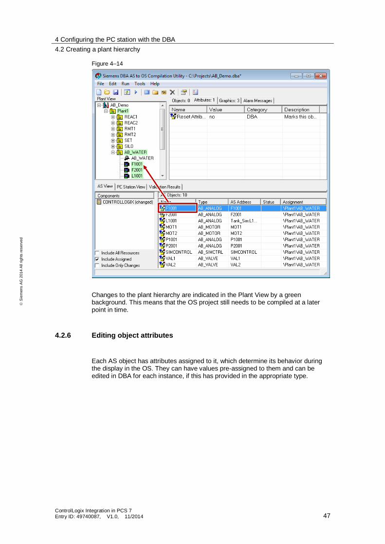
Figure 4–14
Changes to the plant hierarchy are indicated in the Plant View by a green background. This means that the OS project still needs to be compiled at a later point in time.
4.2.6 Editing object attributes
Each AS object has attributes assigned to it, which determine its behavior during the display in the OS. They can have values pre-assigned to them and can be edited in DBA for each instance, if this has provided in the appropriate type.
4 Configuring the PC station with the DBA
4.2 Creating a plant hierarchy
ControlLogix Integration in PCS 7 Entry ID: 49740087, V1.0, 11/2014 48
S
iem
en
s A
G 2
01
4 A
ll ri
gh
ts r
ese
rve
d
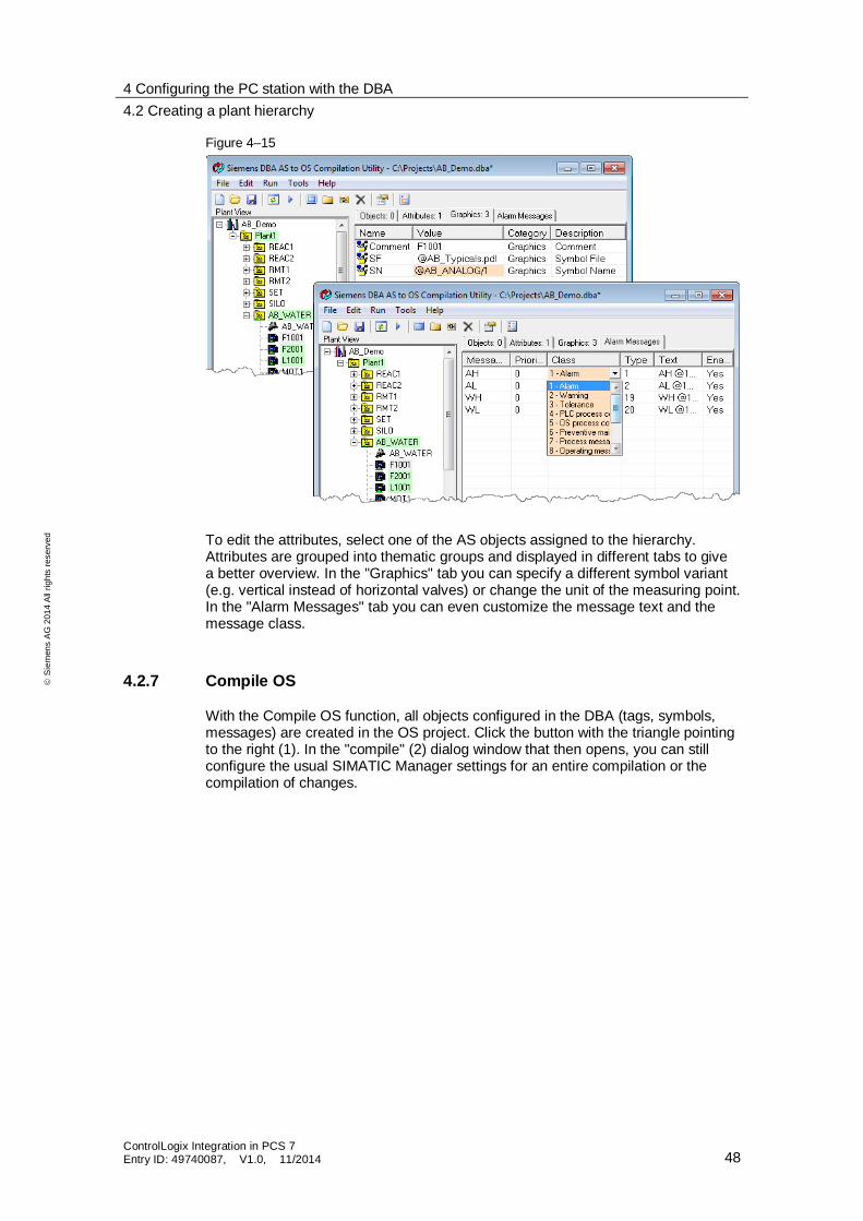
Figure 4–15
To edit the attributes, select one of the AS objects assigned to the hierarchy. Attributes are grouped into thematic groups and displayed in different tabs to give a better overview. In the "Graphics" tab you can specify a different symbol variant (e.g. vertical instead of horizontal valves) or change the unit of the measuring point. In the "Alarm Messages" tab you can even customize the message text and the message class.
4.2.7 Compile OS
With the Compile OS function, all objects configured in the DBA (tags, symbols, messages) are created in the OS project. Click the button with the triangle pointing to the right (1). In the "compile" (2) dialog window that then opens, you can still configure the usual SIMATIC Manager settings for an entire compilation or the compilation of changes.
4 Configuring the PC station with the DBA
4.2 Creating a plant hierarchy
ControlLogix Integration in PCS 7 Entry ID: 49740087, V1.0, 11/2014 49
S
iem
en
s A
G 2
01
4 A
ll ri
gh
ts r
ese
rve
d
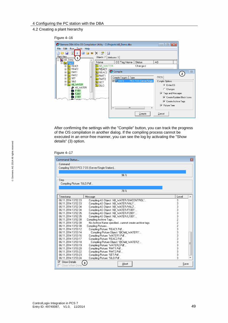
Figure 4–16
After confirming the settings with the "Compile" button, you can track the progress of the OS compilation in another dialog. If the compiling process cannot be executed in an error-free manner, you can see the log by activating the "Show details" (3) option.
Figure 4–17
1
2
3

4 Configuring the PC station with the DBA
4.3 PCS 7 operator station
ControlLogix Integration in PCS 7 Entry ID: 49740087, V1.0, 11/2014 50
S
iem
en
s A
G 2
01
4 A
ll ri
gh
ts r
ese
rve
d
4.3 PCS 7 operator station
When you now open the OS project on the Engineering Station, all connections, tags, messages, process pictures and block icons should be created.
Figure 4–18
1. With the Graphics Designer, open the process pictures that were created using the DBA. The block icons of the AS objects will have been inserted next to one another (1).
2. Draw the process picture according to your requirements and move the block icons into the desired position.
4 Configuring the PC station with the DBA
4.3 PCS 7 operator station
ControlLogix Integration in PCS 7 Entry ID: 49740087, V1.0, 11/2014 51
S
iem
en
s A
G 2
01
4 A
ll ri
gh
ts r
ese
rve
d
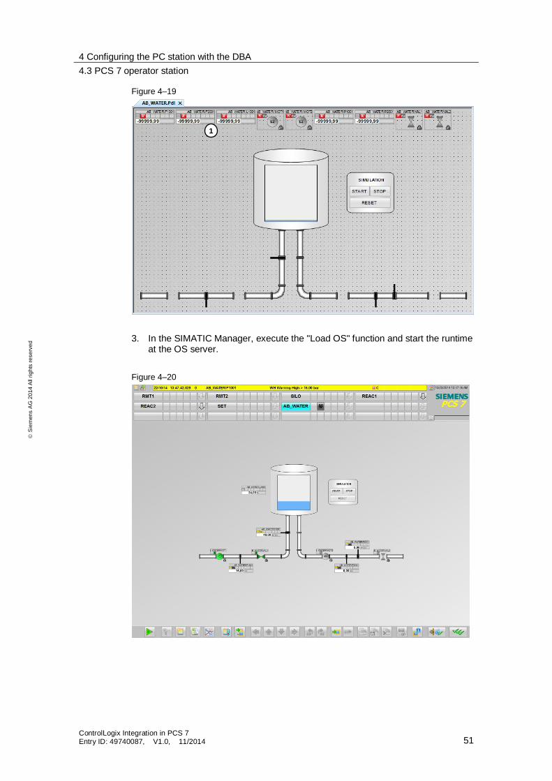
Figure 4–19
3. In the SIMATIC Manager, execute the "Load OS" function and start the runtime at the OS server.
Figure 4–20
1
5 Literature
ControlLogix Integration in PCS 7 Entry ID: 49740087, V1.0, 11/2014 52
S
iem
en
s A
G 2
01
4 A
ll ri
gh
ts r
ese
rve
d
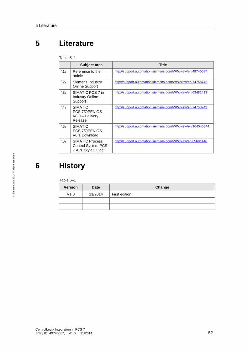
5 Literature
Table 5–1
Subject area Title
\1\ Reference to the article
http://support.automation.siemens.com/WW/view/en/49740087
\2\ Siemens Industry Online Support
http://support.automation.siemens.com/WW/view/en/74758742
\3\ SIMATIC PCS 7 in Industry Online Support
http://support.automation.siemens.com/WW/view/en/63481413
\4\ SIMATIC PCS 7/OPEN OS V8.0 – Delivery Release
http://support.automation.siemens.com/WW/view/en/74758742
\5\ SIMATIC PCS 7/OPEN OS V8.1 Download
http://support.automation.siemens.com/WW/view/en/104546544
\6\ SIMATIC Process Control System PCS 7 APL Style Guide
http://support.automation.siemens.com/WW/view/en/65601446
6 History
Table 6–1
Version Date Change
V1.0 11/2014 First edition