Embed Size (px)
Citation preview
41063-287-01 (1) 990-2954 05/2006
Installation and Operation
User Manual for 350 VA Industrial UPS1609-S350NS - 350 VA, 120 V
1609-S350ES - 350 VA, 208/230 V
Allen-Bradley
3
Installation
Installation
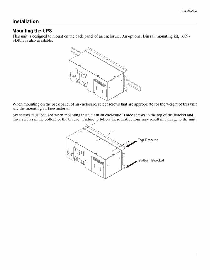
Mounting the UPSThis unit is designed to mount on the back panel of an enclosure. An optional Din rail mounting kit, 1609-SDK1, is also available.
When mounting on the back panel of an enclosure, select screws that are appropriate for the weight of this unit and the mounting surface material.Six screws must be used when mounting this unit in an enclosure. Three screws in the top of the bracket and three screws in the bottom of the bracket. Failure to follow these instructions may result in damage to the unit.
Top Bracket
Bottom Bracket
4
Installation
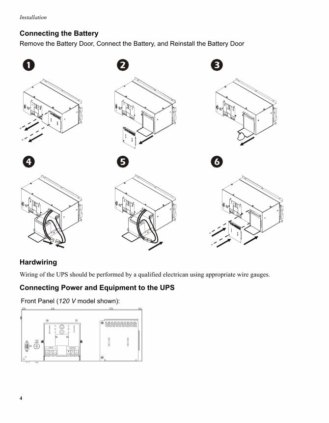
Connecting the BatteryRemove the Battery Door, Connect the Battery, and Reinstall the Battery Door
HardwiringWiring of the UPS should be performed by a qualified electrican using appropriate wire gauges.
Connecting Power and Equipment to the UPS
PUSH TO
RESET
INPUT208/220-240V~ 50/60Hz , 7A MAX
OUTPUT23
325W, 2.7A MAX0V~ 50/60H z, 500VA
LN LNLINENEUTRALGROUND LINENEUTRALGROUND
Test
Front Panel (120 V model shown):
5
Installation
Start-Up
1. The UPS features a transient voltage surge-suppression (TVSS) screw located on the front panel. The TVSS screw is used for connecting the ground lead on surge suppression devices such as telephone and network line protectors.Prior to connecting the grounding cable, ensure that the UPS is NOT connected to utility or battery power.
2. Connect the battery (see Connecting the Battery).3. Hardwire the UPS.
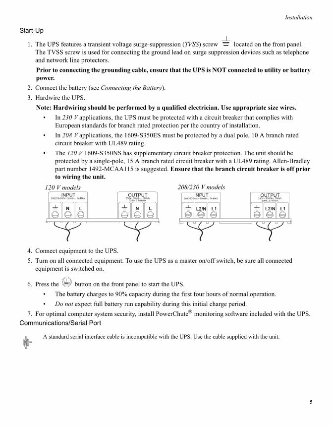
Note: Hardwiring should be performed by a qualified electrician. Use appropriate size wires.� In 230 V applications, the UPS must be protected with a circuit breaker that complies with
European standards for branch rated protection per the country of installation.� In 208 V applications, the 1609-S350ES must be protected by a dual pole, 10 A branch rated
circuit breaker with UL489 rating.� The 120 V 1609-S350NS has supplementary circuit breaker protection. The unit should be
protected by a single-pole, 15 A branch rated circuit breaker with a UL489 rating. Allen-Bradley part number 1492-MCAA115 is suggested. Ensure that the branch circuit breaker is off prior to wiring the unit.
4. Connect equipment to the UPS.5. Turn on all connected equipment. To use the UPS as a master on/off switch, be sure all connected
equipment is switched on.
6. Press the button on the front panel to start the UPS.� The battery charges to 90% capacity during the first four hours of normal operation.� Do not expect full battery run capability during this initial charge period.
7. For optimal computer system security, install PowerChute monitoring software included with the UPS.Communications/Serial Port
A standard serial interface cable is incompatible with the UPS. Use the cable supplied with the unit.
INPUT
LN
OUTPUT
LN
INPUT
L1L2/N
OUTPUT
L1L2/N
208/230 V models120 V models
6
Operation
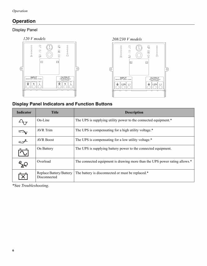
OperationDisplay Panel
Display Panel Indicators and Function Buttons
*See Troubleshooting.
Indicator Title Description
On-Line The UPS is supplying utility power to the connected equipment.*
AVR Trim The UPS is compensating for a high utility voltage.*
AVR Boost The UPS is compensating for a low utility voltage.*
On Battery The UPS is supplying battery power to the connected equipment.
Overload The connected equipment is drawing more than the UPS power rating allows.*
Replace Battery/Battery Disconnected
The battery is disconnected or must be replaced.*
INPUT208/220-240V~ 50/60Hz, 7A MAX
OUTPUT23
325W, 2.7A MAX0V~ 50/60Hz, 500VA
LN LNLINENEUTRALGROUND LINENEUTRALGROUND
Test
INPUT208/220-240V~ 50/60Hz, 7A MAX
OUTPUT23
325W, 2.7A MAX0V~ 50/60Hz, 500VA
L1L2/N L1L2/N
Test
120 V models 208/230 V models
7
Operation
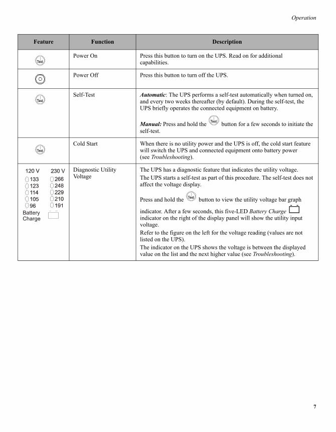
Feature Function Description
Power On Press this button to turn on the UPS. Read on for additional capabilities.
Power Off Press this button to turn off the UPS.
Self-Test Automatic: The UPS performs a self-test automatically when turned on, and every two weeks thereafter (by default). During the self-test, the UPS briefly operates the connected equipment on battery.
Manual: Press and hold the button for a few seconds to initiate the self-test.
Cold Start When there is no utility power and the UPS is off, the cold start feature will switch the UPS and connected equipment onto battery power(see Troubleshooting).
Diagnostic Utility Voltage
The UPS has a diagnostic feature that indicates the utility voltage.The UPS starts a self-test as part of this procedure. The self-test does not affect the voltage display.
Press and hold the button to view the utility voltage bar graph
indicator. After a few seconds, this five-LED Battery Charge indicator on the right of the display panel will show the utility input voltage.Refer to the figure on the left for the voltage reading (values are not listed on the UPS).The indicator on the UPS shows the voltage is between the displayed value on the list and the next higher value (see Troubleshooting).
BatteryCharge
8
User Configurable Items
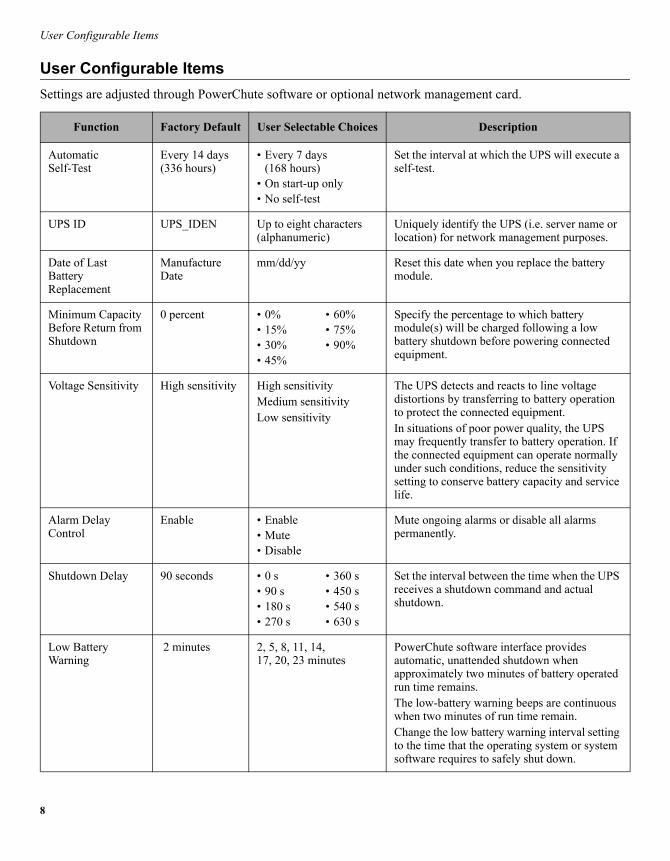
User Configurable ItemsSettings are adjusted through PowerChute software or optional network management card.
Function Factory Default User Selectable Choices Description
AutomaticSelf-Test
Every 14 days (336 hours)
� Every 7 days(168 hours)
� On start-up only� No self-test
Set the interval at which the UPS will execute a self-test.
UPS ID UPS_IDEN Up to eight characters (alphanumeric)
Uniquely identify the UPS (i.e. server name or location) for network management purposes.
Date of LastBatteryReplacement
Manufacture Date
mm/dd/yy Reset this date when you replace the battery module.
Minimum Capacity Before Return from Shutdown
0 percent � 0%� 15%� 30%� 45%
� 60%� 75%� 90%
Specify the percentage to which battery module(s) will be charged following a low battery shutdown before powering connected equipment.
Voltage Sensitivity High sensitivity High sensitivityMedium sensitivityLow sensitivity
The UPS detects and reacts to line voltage distortions by transferring to battery operation to protect the connected equipment.In situations of poor power quality, the UPS may frequently transfer to battery operation. If the connected equipment can operate normally under such conditions, reduce the sensitivity setting to conserve battery capacity and service life.
Alarm DelayControl
Enable � Enable� Mute� Disable
Mute ongoing alarms or disable all alarms permanently.
Shutdown Delay 90 seconds � 0 s� 90 s� 180 s� 270 s
� 360 s� 450 s� 540 s� 630 s
Set the interval between the time when the UPS receives a shutdown command and actual shutdown.
Low BatteryWarning
2 minutes 2, 5, 8, 11, 14, 17, 20, 23 minutes
PowerChute software interface provides automatic, unattended shutdown when approximately two minutes of battery operated run time remains.The low-battery warning beeps are continuous when two minutes of run time remain.Change the low battery warning interval setting to the time that the operating system or system software requires to safely shut down.
9
User Configurable Items
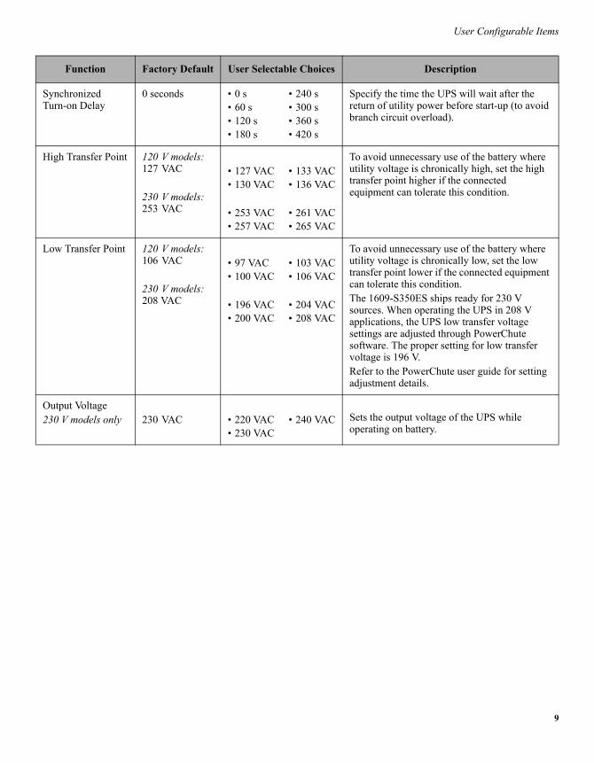
SynchronizedTurn-on Delay
0 seconds � 0 s� 60 s� 120 s� 180 s
� 240 s� 300 s� 360 s� 420 s
Specify the time the UPS will wait after the return of utility power before start-up (to avoid branch circuit overload).
High Transfer Point 120 V models: 127 VAC
230 V models: 253 VAC
� 127 VAC� 130 VAC
� 253 VAC� 257 VAC
� 133 VAC� 136 VAC
� 261 VAC� 265 VAC
To avoid unnecessary use of the battery where utility voltage is chronically high, set the high transfer point higher if the connected equipment can tolerate this condition.
Low Transfer Point 120 V models: 106 VAC
230 V models: 208 VAC
� 97 VAC� 100 VAC
� 196 VAC� 200 VAC
� 103 VAC� 106 VAC
� 204 VAC� 208 VAC
To avoid unnecessary use of the battery where utility voltage is chronically low, set the low transfer point lower if the connected equipment can tolerate this condition.The 1609-S350ES ships ready for 230 V sources. When operating the UPS in 208 V applications, the UPS low transfer voltage settings are adjusted through PowerChute software. The proper setting for low transfer voltage is 196 V. Refer to the PowerChute user guide for setting adjustment details.
Output Voltage230 V models only 230 VAC � 220 VAC
� 230 VAC� 240 VAC Sets the output voltage of the UPS while
operating on battery.
Function Factory Default User Selectable Choices Description
10
Storage, Maintenance, Transport
Storage, Maintenance, Transport
StorageStore the UPS covered in a cool, dry location with the battery module(s) fully charged.At 5° to 86° F (�15° to 30° C), charge the UPS battery module every six months.At 86° to 113° F (30° to 45° C), charge the UPS battery module every three months.
Replacing the Battery ModuleThis UPS has an easy-to-replace, hot-swappable battery module. Replacement is a safe procedure, isolated from electrical hazards. You may leave the UPS and connected equipment on during the replacement procedure.For instruction, see applicable steps in Connecting the Battery.Ensure battery replacement every 2-4 years. Standard (40C) battery; Allen-Bradley catalog number: 1609-500SBAT. Once the battery module(s) are disconnected the connected equipment is not protected from power outages.Refer to the appropriate replacement battery installation guide for battery module installation instructions. See your dealer or contact Rockwell Automation at 440-646-5800 for information on replacement battery modules.
Be sure to deliver the spent battery module(s) to a recycling facility or ship it to the address specified in the replacement battery literature.
11
Troubleshooting
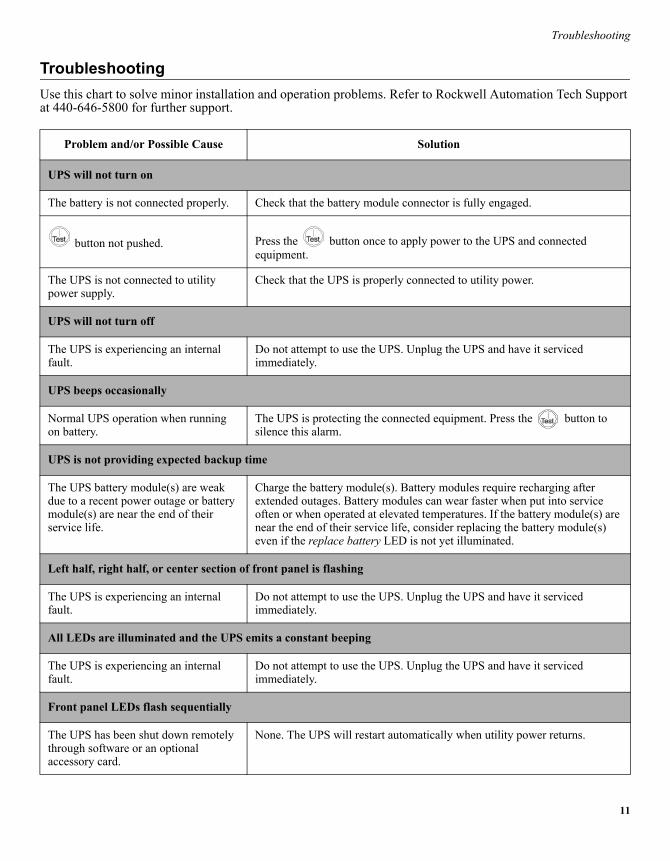
TroubleshootingUse this chart to solve minor installation and operation problems. Refer to Rockwell Automation Tech Support at 440-646-5800 for further support.
Problem and/or Possible Cause Solution
UPS will not turn on
The battery is not connected properly. Check that the battery module connector is fully engaged.
button not pushed. Press the button once to apply power to the UPS and connected equipment.
The UPS is not connected to utility power supply.
Check that the UPS is properly connected to utility power.
UPS will not turn off
The UPS is experiencing an internal fault.
Do not attempt to use the UPS. Unplug the UPS and have it serviced immediately.
UPS beeps occasionally
Normal UPS operation when running on battery.
The UPS is protecting the connected equipment. Press the button to silence this alarm.
UPS is not providing expected backup time
The UPS battery module(s) are weak due to a recent power outage or battery module(s) are near the end of their service life.
Charge the battery module(s). Battery modules require recharging after extended outages. Battery modules can wear faster when put into service often or when operated at elevated temperatures. If the battery module(s) are near the end of their service life, consider replacing the battery module(s) even if the replace battery LED is not yet illuminated.
Left half, right half, or center section of front panel is flashing
The UPS is experiencing an internal fault.
Do not attempt to use the UPS. Unplug the UPS and have it serviced immediately.
All LEDs are illuminated and the UPS emits a constant beeping
The UPS is experiencing an internal fault.
Do not attempt to use the UPS. Unplug the UPS and have it serviced immediately.
Front panel LEDs flash sequentially
The UPS has been shut down remotely through software or an optional accessory card.
None. The UPS will restart automatically when utility power returns.
12
Troubleshooting
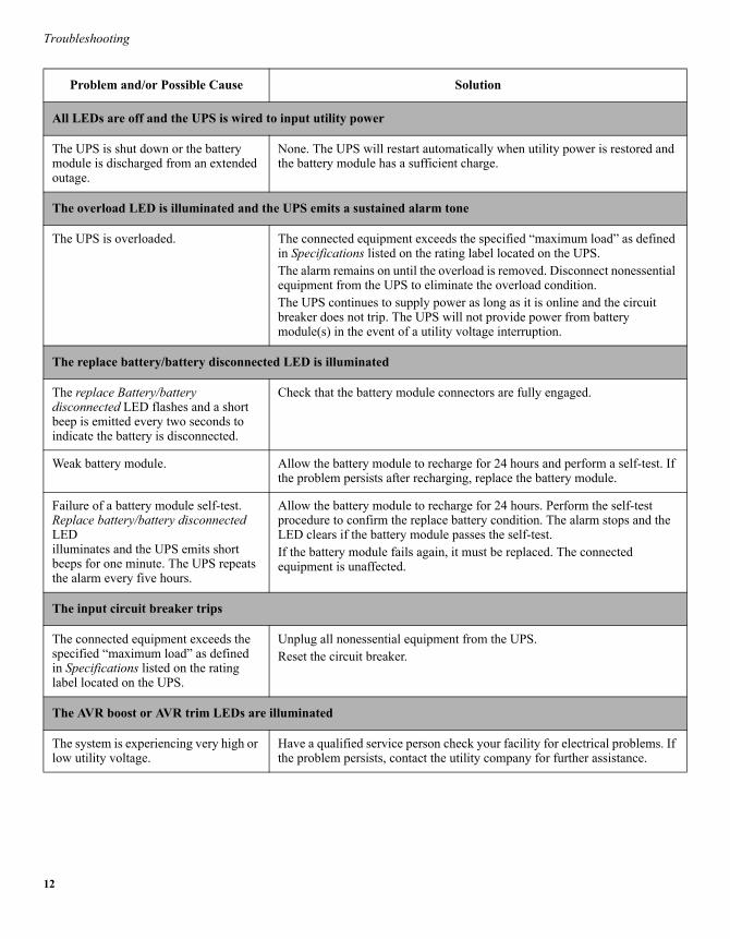
All LEDs are off and the UPS is wired to input utility power
The UPS is shut down or the battery module is discharged from an extended outage.
None. The UPS will restart automatically when utility power is restored and the battery module has a sufficient charge.
The overload LED is illuminated and the UPS emits a sustained alarm tone
The UPS is overloaded. The connected equipment exceeds the specified �maximum load� as defined in Specifications listed on the rating label located on the UPS.The alarm remains on until the overload is removed. Disconnect nonessential equipment from the UPS to eliminate the overload condition.The UPS continues to supply power as long as it is online and the circuit breaker does not trip. The UPS will not provide power from battery module(s) in the event of a utility voltage interruption.
The replace battery/battery disconnected LED is illuminated
The replace Battery/battery disconnected LED flashes and a short beep is emitted every two seconds to indicate the battery is disconnected.
Check that the battery module connectors are fully engaged.
Weak battery module. Allow the battery module to recharge for 24 hours and perform a self-test. If the problem persists after recharging, replace the battery module.
Failure of a battery module self-test. Replace battery/battery disconnected LED illuminates and the UPS emits short beeps for one minute. The UPS repeats the alarm every five hours.
Allow the battery module to recharge for 24 hours. Perform the self-test procedure to confirm the replace battery condition. The alarm stops and the LED clears if the battery module passes the self-test.If the battery module fails again, it must be replaced. The connected equipment is unaffected.
The input circuit breaker trips
The connected equipment exceeds the specified �maximum load� as defined in Specifications listed on the rating label located on the UPS.
Unplug all nonessential equipment from the UPS.Reset the circuit breaker.
The AVR boost or AVR trim LEDs are illuminated
The system is experiencing very high or low utility voltage.
Have a qualified service person check your facility for electrical problems. If the problem persists, contact the utility company for further assistance.
Problem and/or Possible Cause Solution
13
Troubleshooting
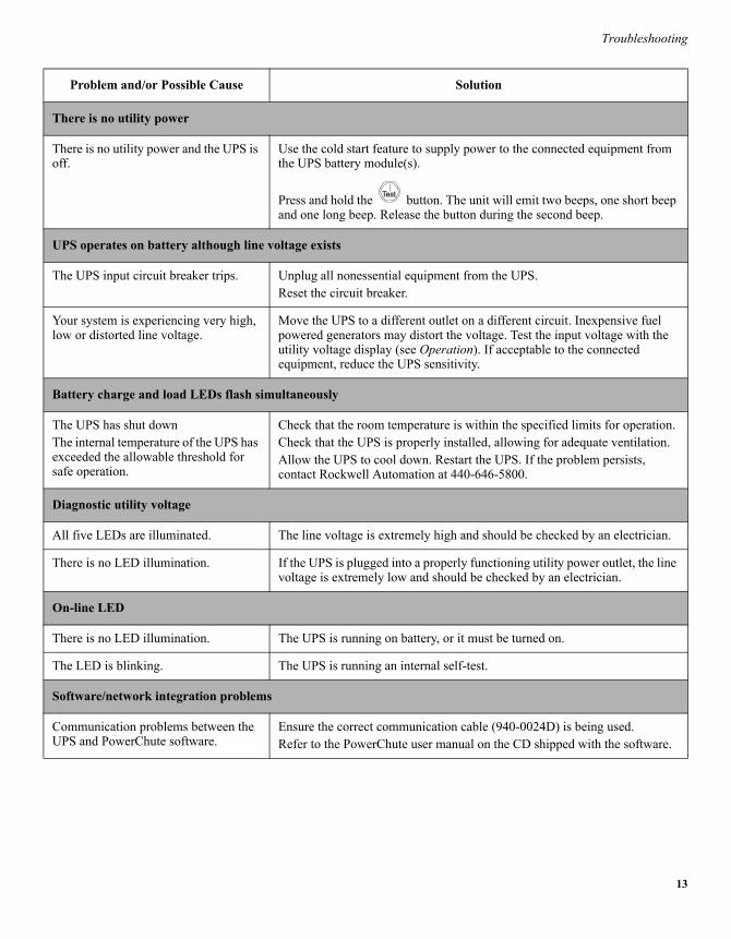
There is no utility power
There is no utility power and the UPS is off.
Use the cold start feature to supply power to the connected equipment from the UPS battery module(s).
Press and hold the button. The unit will emit two beeps, one short beep and one long beep. Release the button during the second beep.
UPS operates on battery although line voltage exists
The UPS input circuit breaker trips. Unplug all nonessential equipment from the UPS.Reset the circuit breaker.
Your system is experiencing very high, low or distorted line voltage.
Move the UPS to a different outlet on a different circuit. Inexpensive fuel powered generators may distort the voltage. Test the input voltage with the utility voltage display (see Operation). If acceptable to the connected equipment, reduce the UPS sensitivity.
Battery charge and load LEDs flash simultaneously
The UPS has shut downThe internal temperature of the UPS has exceeded the allowable threshold for safe operation.
Check that the room temperature is within the specified limits for operation.Check that the UPS is properly installed, allowing for adequate ventilation.Allow the UPS to cool down. Restart the UPS. If the problem persists, contact Rockwell Automation at 440-646-5800.
Diagnostic utility voltage
All five LEDs are illuminated. The line voltage is extremely high and should be checked by an electrician.
There is no LED illumination. If the UPS is plugged into a properly functioning utility power outlet, the line voltage is extremely low and should be checked by an electrician.
On-line LED
There is no LED illumination. The UPS is running on battery, or it must be turned on.
The LED is blinking. The UPS is running an internal self-test.
Software/network integration problems
Communication problems between the UPS and PowerChute software.
Ensure the correct communication cable (940-0024D) is being used.Refer to the PowerChute user manual on the CD shipped with the software.
Problem and/or Possible Cause Solution
14
Service and Contact Information
Service and Contact Information
ServiceIf the UPS requires service do not return it to the dealer. Follow these steps:
1. Review the problems discussed in Troubleshooting to eliminate common problems.2. If the problem persists, contact Rockwell Automation Customer Support.
� If the product is determined to be defective, contact the distributor for typical return procedures.� Retain the battery module.
3. Pack the UPS in its original packaging.� Pack the UPS properly to avoid damage in transit. Never use Styrofoam beads for packaging.
Damage sustained in transit is not covered under warranty.� Always DISCONNECT THE BATTERY MODULE before shipping in compliance with
U.S. Department of Transportation (DOT) and IATA regulations. The battery module may remain in the UPS.
.
Allen-Bradley Company, LLCIndustrial Components Business1201 South Second StreetMilwaukee, WI 53204-2496 USAPhone 440.646.5800www.ab.com
41063-287-01 (1)