Embed Size (px)
Citation preview
1
INTEGRATION OF EXPERIMENTAL FACILITIES: A JOINT EFFORT FOR ESTABLISHING A COMMON KNOWLEDGE BASE IN
EXPERIMENTAL WORK ON HYDROGEN SAFETY
Reinecke, E.-A.1, Huebert, Th.2, Tkatschenko, I.3, Kessler, A.4, Kuznetsov, M.5, Wilkins, B.A.6, Hedley, D.7, Azkarate, I.8, Proust, Ch.9, Acosta-Iborra, B.10, Gavrikov, A.11, De Bruijn, P.C.J.12,
Marangon, A.13, Teodorczyk, A.14, Grafwallner, F.15
1 Institute of Energy Research IEF-6, Forschungszentrum Juelich GmbH,
Juelich, 52425, Germany, [email protected] 2 BAM, Berlin, Germany
3 Commissariat a l'Energie Atomique, France 4 Fraunhofer-ICT, Pfinztal, Germany
5 Forschungszentrum Karlsruhe, Germany 6 GexCon AS, Bergen, Norway
7 Health and Safety Executive, Buxton, UK 8 INASMET-Tecnalia, San Sebastian, Spain
9 INERIS, Verneuil-en-Halatte, France 10 JRC, Institute for Energy, Petten, The Netherlands
11 RRC Kurchatov Institute, Moscow, Russia 12 TNO, Rijswijk, The Netherlands
13 University of Pisa, Italy 14 Warsaw University of Technology, Poland 15 EnergieTechnologie, Brunnthal, Germany
ABSTRACT
With regard to the goals of the European HySafe Network, research facilities are essential for the experimental investigation of relevant phenomena, for testing devices and safety concepts as well as for the generation of validation data for the various numerical codes and models. The integrating activity ‘Integration of Experimental Facilities (IEF)’ has provided basic support for jointly performed experimental work within HySafe. Even beyond the funding period of the NoE HySafe in the 6th Framework Programme, IEF represents a long lasting effort for reaching sustainable integration of the experimental research capacities and expertise of the partners from different research fields. In order to achieve a high standard in the quality of experimental data provided by the partners, emphasis was put on the know-how transfer between the partners. The strategy for reaching the objectives consisted of two parts. On the one hand, a documentation of the experimental capacities has been prepared and analysed. On the other hand, a communication base has been established by means of biannual workshops on experimental issues. A total of 8 well received workshops has been organised covering topics from measurement technologies to safety issues. Based on the information presented by the partners, a working document on best practice including the joint experimental knowledge of all partners with regard to experiments and instrumentation was created. Preserving the character of a working document, it was implemented in the IEF wiki website, which was set up in order to provide a central communication platform. The paper gives an overview of the IEF network activities over the last 5 years.
2
1.0 INTRODUCTION
The introduction and commercialisation of hydrogen as an energy carrier of the future makes great demands on all aspects of safety. In the frame of the 6th European Framework Programme, the HySafe Network of Excellence (NoE) has been aiming at the integration of the European research activities in the area of hydrogen safety and to disseminate the knowledge and achievements in order to support the safe and efficient introduction and commercialisation of hydrogen as an energy carrier of the future. 24 partners from such different fields as automotive industry, nuclear safety research, or risk assessment consultancy have contributed to this effort [1].
All activities and projects of HySafe have been organised in the four clusters ‘Basic research’, ‘Risk management’, ‘Dissemination’ and ‘Management’. Among these, the work of the cluster ‘Basic Research’ mainly consists of knowledge consolidation providing a well structured hardware and software infrastructure for the network. In this way, the cluster has supported e.g. the internal projects InsHyde (Releases in confined and partially confined spaces) and HyTunnel (Safe tunnels for H2 vehicles). The capability of adequately assessing different accident scenarios has been demonstrated in a set of numerical benchmark studies. For validation purposes, these numerical studies are based on high quality experimental data, especially with regard to the increasing capabilities of high resolution CFD (Computational Fluid Dynamics) tools.
Consequently, the objectives of the activity Integration of Experimental Facilities (IEF) were to enable the HySafe network to jointly perform high level experimental research by supporting the partners’ development of excellence, broadening the fields of experience, and at the same time enhancing the communication and knowledge base.
At the beginning of HySafe, the IEF partners were operating numerous test facilities in national or international projects for diverse research tasks reaching from material research in laboratory scale to full scale explosion studies. Consequently, there was a need to identify the partners’ best expertise, potentially overlapping activities but also possible gaps. Furthermore, the exchange of expertise and know-how between the partners has been regarded as one of the keys to provide high quality experimental data.
The strategy for reaching the IEF objectives consisted of two parts. On the one hand, a documentation of the experimental capacities has been compiled and analysed. On the other hand, a common communication base has been established by means of biannual workshops on experimental issues.
2.0 THE PARTNERS
The experimental activities in the field of hydrogen safety in Europe mainly originate from two areas: On the one hand, hydrogen safety research has developed from safety investigations for natural gas applications. On the other hand, in the field of nuclear technology, hydrogen is a safety issue in ‘severe accident’ research since more than 20 years. In the frame of IEF, 15 partners from both research fields have been contributing with their specific expertise. Furthermore, the partners originate from private and governmental research, industry and universities with certain historical differences in the methodologies and approaches for addressing safety issues. These partners are
• Bundesanstalt für Materialforschung und -prüfung (BAM), Germany BAM and its precursor bodies care for public safety and technical reliability since 1870 on the basis of legal tasks but also by independent application directed research. The fields of activity include testing and investigating classical (like metals) and advanced (like composites) materials as well as the safe handling of flammable, explosive, or otherwise dangerous substances (gases, explosives) and the development of new test and investigation methods.
3
BAM facilities and expertise are frequently used by external parties from industry and also as standard for comparative experiments.
• Commissariat à l’Energie Atomique (CEA), France CEA has been involved in the field of hydrogen safety issues for more than ten years, initially in the framework of the so-called ‘H2 risk’ for pressurised water nuclear reactor containments. In the past two years, CEA has also launched a programme on H2 technologies which covers topics such as production of hydrogen, storage, fuel cells and safety.
• Fraunhofer Institut Chemische Technologie (Fh-ICT), Germany The Fraunhofer-Gesellschaft zur Förderung der angewandten Forschung e.V. (FhG) is a non-profit registered, autonomous association to link between science and industry with a decentralised organisational structure, which currently maintains 58 research institutes. Fh-ICT is one of the research institutes with a long experience on energetic materials and combustion, explosion, and detonation explorations. High level measuring equipment in the field of pressure, temperature, radiation, local-resolved concentration, fragment impact and different laboratories and testing areas are establishing the basis for wide-spread research concerning energetic phenomena.
• Forschungszentrum Juelich GmbH (FZJ), Germany Forschungszentrum Juelich GmbH is one of the 15 Helmholtz Research Centres in Germany (Helmholtz Community of German Research Centers, HGF). In the area of hydrogen safety the research programme of FZJ addresses the safety issues of devices for control of hydrogen focusing on the application of passive auto-catalytic recombiners. The scientific programme includes both experimental and theoretical investigations, thus providing a data base for model validation and aiming at optimising safety concepts as well as the development of new safety directed solutions in such fields where no suitable measures exist. The hydrogen laboratory provides several small and medium scale facilities for testing and investigating hydrogen mitigation devices.
• Forschungszentrum Karlsruhe GmbH (FZK), Germany Forschungszentrum Karlsruhe GmbH is an independent science and research institution in Germany. The goal of the hydrogen safety research programme at FZK is to provide an adequate scientific basis for reliable hydrogen control in nuclear power plants. The safety analysis methodology is also being applied to hydrogen safety studies for fusion technology (ITER) and to safety of hydrogen as an energy carrier. The main scientific objective of this work is the development of new improved methods for prediction of explosion hazards in complex 3D domains. For experimental validation of 3D combustion codes, FZK has constructed and is operating a number of combustion research facilities with different scales and confinements.
• GexCon AS (GexCon), Norway GexCon is a 20-person company with highly qualified people specialising into explosion safety. GexCon has both test laboratories and sites, as well as own commercially available explosion software. GexCon has been among the leading groups for offshore explosion safety work since 1980 with more than 20 years experience from explosion research, including reactive cloud generation and mitigation.
• The United Kingdom’s Health and Safety Laboratory (HSL), United Kingdom The Health & Safety Laboratory (HSL) is part of the UK regulatory authority, the Health & Safety Executive (HSE). HSL has developed an international reputation in combustion hazards, including dispersion, ignition, explosion assessment, prevention and protection, process safety and fire. HSL has extensive experimental and modelling facilities. Relevant current work includes experimental study of ignited / unignited pressurised H2 releases and mechanical ignition of explosive atmospheres.

4
• Fundación INASMET-Tecnalia (INASMET), Spain INASMET is a Materials and Processes Research Centre focused on industrial applications. With a staff of 250 people, INASMET is organized in five Units: Aerospace, Automotive, Energy, Environment, Foundry and Health. The Energy Unit, with a staff of 47 people, is organized in three departments: ‘Hydrogen Chain’, ‘Materials and Components for Renewable Energies’ and ‘Bioenergy’. The activity of these departments is concentrated on the development of materials and components for energy applications and to the study of their behaviour in service conditions. Hydrogen and related technologies is one of the main subjects of the unit and covers all related steps, production, storage and use of hydrogen as energy carrier. All these activities are supported by the general laboratories of INASMET for a whole, mechanical, chemical and microstructural characterization of materials.
• Institut National de l’Environnement Industriel et des Risques (INERIS), France INERIS is a French governmental organisation providing government and industry with expertise in the field of protection of ecosystems and human health from human activities, especially industry. INERIS has a mission of assessing and preventing accidental and chronic risks to people and the environment due to human activities through all media (air, soil and water), taking into account the diversity of their consequences (physical, chemical, toxic as well as economic). INERIS is currently strongly developing his role in research and consultancy in the area of economic analysis of environmental regulations and policies.
• The EC's Joint Research Centre - Institute for Energy (JRC), Netherlands The JRC's Institute of Energy is one of the seven Research Institutes of the European Commission's Joint Research Centre (JRC) and provides support to the European policy-making process and focal point for industry in the area of clean and sustainable energy in both nuclear and non-nuclear domains. Regarding integration of experimental facilities, the JRC has a full scale tank testing facility, GasTeF for comparing and assessing safety, performance and storage of hydrogen containers and the sensor testing facility SenTeF. In GasTeF high pressure cycling and permeation measurements on compressed hydrogen storage systems for vehicles are carried out. In SenTeF performance characterisation of hydrogen sensors under a wide range of environmental conditions for safety is made.
• Russian Research Center Kurchatov Institute (KI), Russia The Kurchatov Institute is a governmental science and research center in Russia. One of the main goals of the hydrogen safety research programme at KI is to provide an adequate scientific basis for reliable hydrogen control and mitigation in nuclear power plants. The main scientific objective of this work is the development of new improved methods for prediction and mitigation of explosion hazards in a complex geometry. For development of different combustion criteria and experimental validation of 3D combustion codes, KI has constructed and is operating a number of combustion research facilities of different scales and confinements for normal and elevated initial conditions.
• The Netherlands Organisation for Applied Scientific Research (TNO), Netherlands TNO is an independent organisation subject to the law of the Netherlands. TNO’s portfolio of knowledge is distributed across 5 core areas. TNO Defence, Security and Safety is the core area with research laboratories operating in the field of explosion safety. Within the explosion safety field, a wide experience regarding safe handling and manufacturing of all kind of energetic and thermally unstable materials has been built up over the last decades.
• University of Pisa – DIMNP (UNIPI), Italy The Department of Mechanics, Nuclear and Production Engineering (DIMNP) of the University of Pisa has a 25 years standing experience in the field of hydrogen risks (theoretical, code development and experimental). From an experimental point of view, many apparatus were built to analyse hydrogen-air combustion phenomena. Recently, a new facility
5
has been set up, in relatively large scale (30 m³), to investigate the behaviour of vented combustion parameters with uniform and non-uniform initial mixtures.
• Warsaw University of Technology (WUT), Poland The Institute of Heat Engineering (IHE) is an education and scientific research unit of the Warsaw University of Technology (WUT). The institute includes three separate laboratories where detonation tube facilities for detailed studies on detonation phenomena are operated.
The expertise of these initial IEF partners has been complemented by EnergieTechnologie (ET), Germany, a company active in the field of hydrogen application testing. ET EnergieTechnologie is the expert in testing hydrogen storage systems and components, which are used in the automotive and aerospace industry. ET EnergieTechnologie is the only service provider worldwide, who is in a position to combine both: cryogenic and high-pressure hydrogen applications. ET has joined the activity IEF as so-called ‘active supporter’ - a status that allows ET to participate in specific tasks of the network without being full member of the decision making groups in HySafe.
Table 1 gives an overview of the structure of the IEF consortium.
Table 1. Structure of the IEF consortium
Private Research Organisation Fh-ICT, FZJ, FZK, INASMET, INERIS, TNO Governmental Research Organisation BAM, CEA, HSL, KI European Research Organisation JRC Industry GexCon, ET University UNIPI, WUT
3.0 THE FACILITIES
The in total 109 experimental facilities available at the IEF partners spread over a wide range of scales and applications with regard to hydrogen safety research. As a first overview, Table 2 gives a brief - however rough - summary of the specific experimental orientation and capacities of the partners.
In the frame of the network activities, the total of 109 facilities has been categorised in order to identify specific expertise, map research needs with research possibilities in order to identify gaps, and enhance the presentation of the facilities.
As a basis for the categorisation, the phenomena and parameters related to accidental events and possible consequences introduced in the Phenomena Identification and Ranking Table (PIRT) have been used. The PIRT exercise had been performed in the framework of HySafe with the objective of identifying and prioritising R&D needs in the area of H2 safety. The main categories characterising the main fields of application of the experimental facilities are:
• Gaseous release
• Dispersion
• Ignition
• Combustion/explosion
• Liquid release
• Explosion of liquid storage
6
• Mitigation
• Equipment and device testing
Table 2. Summary of the facilities operated by the IEF partners
Partner Experimental facilities BAM Small and large-scale test facilities for material testing, sensor testing and gas
explosion experiments CEA Facilities for gas release and distribution experiments Fh-ICT Small and large-scale test facilities for H2 deflagration and detonation
experiments FZJ Small-scale test facilities for studying hydrogen mitigation devices FZK Small-scale and large-scale facilities to study H2 explosion phenomena and
H2 distribution GexCon Small and large-scale test facilities for explosion experiments HSL Small and large fire and explosion test facilities, facilities for assessing
dispersion and mixing of both gaseous and two-phase flashing flows, facilities for ignition research, facilities for jet and pool fire testing, impact test facilities including air cannon and impact test track
INASMET Small scale facilities for studying the effect of hydrogen on materials behaviour
INERIS Facilities to study hydrogen combustion propagation in industrial pipes, unconfined jet release of hydrogen (free or impinged jet), confined hydrogen explosion and explosion venting, slow release of hydrogen in confined spaces (garage), and pressurised tank and liquid tanks testing
JRC Compressed Gas Hydrogen tank testing facility, solid state storage facility and hydrogen sensor testing facility
KI Several combustion tubes, special vented tubes, scaled multi-compartment facilities for FA and DDT studies, spray facility for experiments with liquid fuel, bunker facility
TNO Small and large-scale test facilities for combustion and explosion experiments, IBBC Bunker for (semi)confined explosions, rigs for testing confined explosions, detonation tube facilities, explosion facility (e.g. for testing rocket engines)
UNIPI Large-scale CVE facility (30 m³) for confined vented explosion experiments WUT Detonation tube facility for studies of gaseous detonations ET Cryogenic hydrogen test facilities: ambient pressure to 40 MPa, High-
pressure hydrogen test facilities: pressures up to > 100 MPa, Hydraulic burst tests, Leak / permeation measurement, Material / embrittlement test facilities: 100 MPa, 300 °C
‘Equipment and device testing’ was not included in the PIRT but represents an important type of experimental research activity within HySafe. The sub-categories ‘phenomena’ given in Table 3 have been applied as well according to the PIRT.
For the total of 109 facilities fact sheets have been provided by the IEF partners containing basic technical information on the facilities. An on-line version has been implemented in the HySafe web page as well. A similar compilation of fact sheets has been performed for the instrumentation of the facilities. The following sub-chapters give some examples of the facilities integrated in IEF in order to give an impression on the vast diversity of the facilities available for research on hydrogen safety. The
7
full range of categories identified as being relevant for hydrogen safety issues is covered by the IEF facilities.
Table 3. Categories applied to the experimental facilities
Main category Sub-categories ‘phenomena’ Gaseous release - permeation - full bore rupture (pipe),
- subsonic release full vessel rupture - choked flow (sonic) release - turbulent flow in pipes, H2 transport
Dispersion - impinged jets - buoyancy effects - obstacle-generated turbulence - stable stratification - effect of obstacles on flow - turbulent mixing (velocity gradients) patterns - turbulent mixing (decaying - atmospheric conditions (wind) conditions) - heat transfer from environment - laminar diffusion - natural ventilation - compressible effect (shocks, - forced ventilation under-expanded jets, contacts)
Ignition - auto-ignition - direct initiation of detonation - shock ignition - jet ignition - weak/mild ignition (incl. static - radiative ignition electricity [forced ignition] - hot surface ignition - strong ignition [forced ignition] - flammability limits
Combustion/Explosion - laminar flame - DDT - cellular flame - detonation - wrinkled flame - quenching (global or local) - self turbulising flame - standing flame, diffusion flame - flame acceleration/deceleration - jet fire (due to obstacles, conc. grad.) - spill fire - triple flame - multiphase combustion (LH2) - turbulent deflagration - heat radiation & absorption
Liquid release and spill - liquid (two-phase) flow through - spill evaporation orifice - two-phase flow in liquid, boiling - full bore liquid (pipelines) - heat transfer from ground full vessel release - condensation (20-90 K) and - formation of spill, pool spreading evaporation (>90 K) of air
Explosion of liquid storage - heat conduction in storage material - boiling liquid expanding vapour explosion (BLEVE)
Mitigation - natural ventilation - venting of deflagration - forced ventilation - pressurisation of zone to avoid - post-accident inerting entry of H2 - recombiners - shut down systems - preventive ignition, igniters - blast wave protective wall interaction
Equipment/device testing - performance tests: sensors, igniters, recombiners - storage tests - material tests - impact tests: explosion, thermal, mechanical, dynamic pressure
3.1 Gaseous release
Gaseous releases of hydrogen need to be investigated starting from small release rates resulting from permeation up to full bore rupture (pipe) or full vessel rupture.
The HyJet facility at FZK (Fig. 1, left) enables studies in the small and medium scale on hydrogen release from pressurised vessel, dynamic measurement of hydrogen concentrations and flow velocity profiles, and investigations on the flammability of the turbulent hydrogen jet. Different nozzle diameters and a hydrogen mass flow of up to 10 g/s (stationary) or up to 100 g/s (temporary) enable
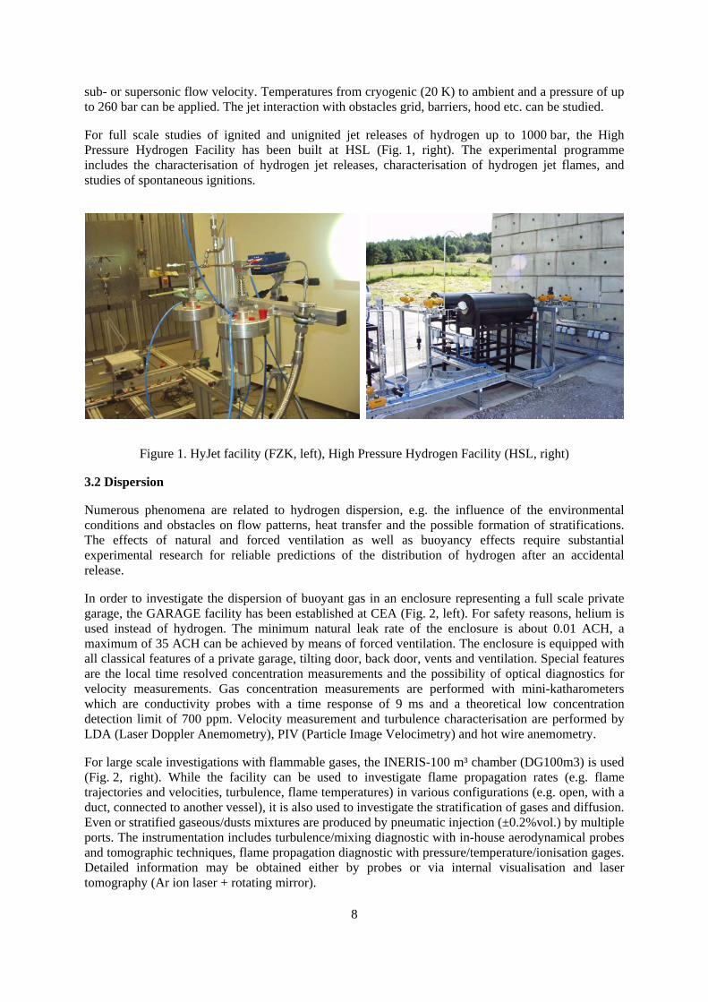
sub- or supersonic flow velocity. Temperatures from cryogenic (20 K) to ambient and a pressure of up to 260 bar can be applied. The jet interaction with obstacles grid, barriers, hood etc. can be studied.
For full scale studies of ignited and unignited jet releases of hydrogen up to 1000 bar, the High Pressure Hydrogen Facility has been built at HSL (Fig. 1, right). The experimental programme includes the characterisation of hydrogen jet releases, characterisation of hydrogen jet flames, and studies of spontaneous ignitions.
Figure 1. HyJet facility (FZK, left), High Pressure Hydrogen Facility (HSL, right)
3.2 Dispersion
Numerous phenomena are related to hydrogen dispersion, e.g. the influence of the environmental conditions and obstacles on flow patterns, heat transfer and the possible formation of stratifications. The effects of natural and forced ventilation as well as buoyancy effects require substantial experimental research for reliable predictions of the distribution of hydrogen after an accidental release.
In order to investigate the dispersion of buoyant gas in an enclosure representing a full scale private garage, the GARAGE facility has been established at CEA (Fig. 2, left). For safety reasons, helium is used instead of hydrogen. The minimum natural leak rate of the enclosure is about 0.01 ACH, a maximum of 35 ACH can be achieved by means of forced ventilation. The enclosure is equipped with all classical features of a private garage, tilting door, back door, vents and ventilation. Special features are the local time resolved concentration measurements and the possibility of optical diagnostics for velocity measurements. Gas concentration measurements are performed with mini-katharometers which are conductivity probes with a time response of 9 ms and a theoretical low concentration detection limit of 700 ppm. Velocity measurement and turbulence characterisation are performed by LDA (Laser Doppler Anemometry), PIV (Particle Image Velocimetry) and hot wire anemometry.
For large scale investigations with flammable gases, the INERIS-100 m³ chamber (DG100m3) is used (Fig. 2, right). While the facility can be used to investigate flame propagation rates (e.g. flame trajectories and velocities, turbulence, flame temperatures) in various configurations (e.g. open, with a duct, connected to another vessel), it is also used to investigate the stratification of gases and diffusion. Even or stratified gaseous/dusts mixtures are produced by pneumatic injection (±0.2%vol.) by multiple ports. The instrumentation includes turbulence/mixing diagnostic with in-house aerodynamical probes and tomographic techniques, flame propagation diagnostic with pressure/temperature/ionisation gages. Detailed information may be obtained either by probes or via internal visualisation and laser tomography (Ar ion laser + rotating mirror).
8
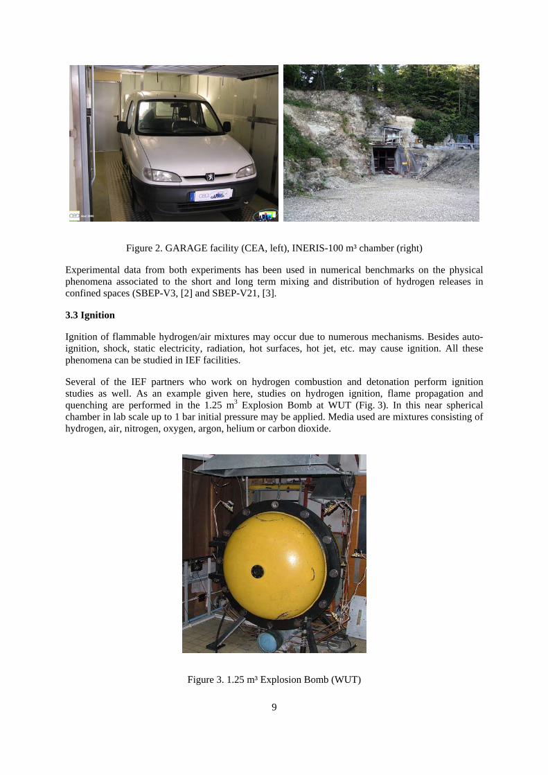
Figure 2. GARAGE facility (CEA, left), INERIS-100 m³ chamber (right)
Experimental data from both experiments has been used in numerical benchmarks on the physical phenomena associated to the short and long term mixing and distribution of hydrogen releases in confined spaces (SBEP-V3, [2] and SBEP-V21, [3].
3.3 Ignition
Ignition of flammable hydrogen/air mixtures may occur due to numerous mechanisms. Besides auto-ignition, shock, static electricity, radiation, hot surfaces, hot jet, etc. may cause ignition. All these phenomena can be studied in IEF facilities.
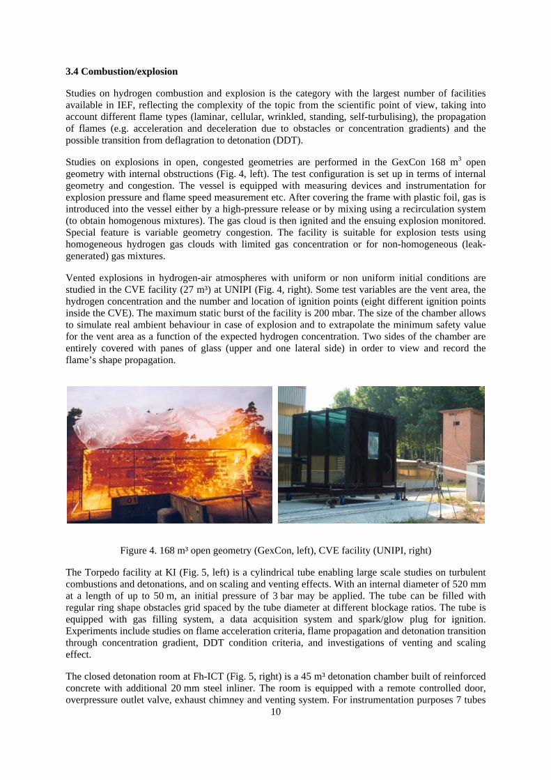
Several of the IEF partners who work on hydrogen combustion and detonation perform ignition studies as well. As an example given here, studies on hydrogen ignition, flame propagation and quenching are performed in the 1.25 m3 Explosion Bomb at WUT (Fig. 3). In this near spherical chamber in lab scale up to 1 bar initial pressure may be applied. Media used are mixtures consisting of hydrogen, air, nitrogen, oxygen, argon, helium or carbon dioxide.
Figure 3. 1.25 m³ Explosion Bomb (WUT)
9
3.4 Combustion/explosion
Studies on hydrogen combustion and explosion is the category with the largest number of facilities available in IEF, reflecting the complexity of the topic from the scientific point of view, taking into account different flame types (laminar, cellular, wrinkled, standing, self-turbulising), the propagation of flames (e.g. acceleration and deceleration due to obstacles or concentration gradients) and the possible transition from deflagration to detonation (DDT).
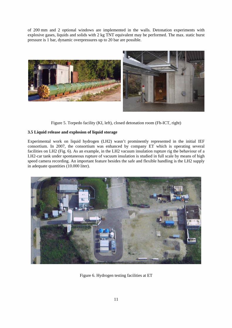
Studies on explosions in open, congested geometries are performed in the GexCon 168 m3 open geometry with internal obstructions (Fig. 4, left). The test configuration is set up in terms of internal geometry and congestion. The vessel is equipped with measuring devices and instrumentation for explosion pressure and flame speed measurement etc. After covering the frame with plastic foil, gas is introduced into the vessel either by a high-pressure release or by mixing using a recirculation system (to obtain homogenous mixtures). The gas cloud is then ignited and the ensuing explosion monitored. Special feature is variable geometry congestion. The facility is suitable for explosion tests using homogeneous hydrogen gas clouds with limited gas concentration or for non-homogeneous (leak-generated) gas mixtures.
Vented explosions in hydrogen-air atmospheres with uniform or non uniform initial conditions are studied in the CVE facility (27 m³) at UNIPI (Fig. 4, right). Some test variables are the vent area, the hydrogen concentration and the number and location of ignition points (eight different ignition points inside the CVE). The maximum static burst of the facility is 200 mbar. The size of the chamber allows to simulate real ambient behaviour in case of explosion and to extrapolate the minimum safety value for the vent area as a function of the expected hydrogen concentration. Two sides of the chamber are entirely covered with panes of glass (upper and one lateral side) in order to view and record the flame’s shape propagation.
Figure 4. 168 m³ open geometry (GexCon, left), CVE facility (UNIPI, right)
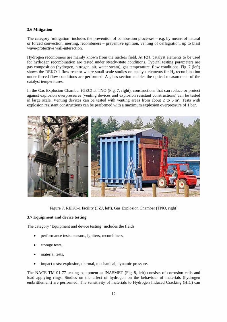
The Torpedo facility at KI (Fig. 5, left) is a cylindrical tube enabling large scale studies on turbulent combustions and detonations, and on scaling and venting effects. With an internal diameter of 520 mm at a length of up to 50 m, an initial pressure of 3 bar may be applied. The tube can be filled with regular ring shape obstacles grid spaced by the tube diameter at different blockage ratios. The tube is equipped with gas filling system, a data acquisition system and spark/glow plug for ignition. Experiments include studies on flame acceleration criteria, flame propagation and detonation transition through concentration gradient, DDT condition criteria, and investigations of venting and scaling effect.
10
The closed detonation room at Fh-ICT (Fig. 5, right) is a 45 m³ detonation chamber built of reinforced concrete with additional 20 mm steel inliner. The room is equipped with a remote controlled door, overpressure outlet valve, exhaust chimney and venting system. For instrumentation purposes 7 tubes
of 200 mm and 2 optional windows are implemented in the walls. Detonation experiments with explosive gases, liquids and solids with 2 kg TNT equivalent may be performed. The max. static burst pressure is 1 bar, dynamic overpressures up to 20 bar are possible.
Figure 5. Torpedo facility (KI, left), closed detonation room (Fh-ICT, right)
3.5 Liquid release and explosion of liquid storage
Experimental work on liquid hydrogen (LH2) wasn’t prominently represented in the initial IEF consortium. In 2007, the consortium was enhanced by company ET which is operating several facilities on LH2 (Fig. 6). As an example, in the LH2 vacuum insulation rupture rig the behaviour of a LH2-car tank under spontaneous rupture of vacuum insulation is studied in full scale by means of high speed camera recording. An important feature besides the safe and flexible handling is the LH2 supply in adequate quantities (10.000 liter).
Figure 6. Hydrogen testing facilities at ET
11
3.6 Mitigation
The category ‘mitigation’ includes the prevention of combustion processes – e.g. by means of natural or forced convection, inerting, recombiners – preventive ignition, venting of deflagration, up to blast wave-protective wall-interaction.
Hydrogen recombiners are mainly known from the nuclear field. At FZJ, catalyst elements to be used for hydrogen recombination are tested under steady-state conditions. Typical testing parameters are gas composition (hydrogen, nitrogen, air, water steam), gas temperature, flow conditions. Fig. 7 (left) shows the REKO-1 flow reactor where small scale studies on catalyst elements for H2 recombination under forced flow conditions are performed. A glass section enables the optical measurement of the catalyst temperatures.
In the Gas Explosion Chamber (GEC) at TNO (Fig. 7, right), constructions that can reduce or protect against explosion overpressures (venting devices and explosion resistant constructions) can be tested in large scale. Venting devices can be tested with venting areas from about 2 to 5 m2. Tests with explosion resistant constructions can be performed with a maximum explosion overpressure of 1 bar.
Figure 7. REKO-1 facility (FZJ, left), Gas Explosion Chamber (TNO, right)
3.7 Equipment and device testing
The category ‘Equipment and device testing’ includes the fields
• performance tests: sensors, igniters, recombiners,
• storage tests,
• material tests,
• impact tests: explosion, thermal, mechanical, dynamic pressure.
The NACE TM 01-77 testing equipment at INASMET (Fig. 8, left) consists of corrosion cells and load applying rings. Studies on the effect of hydrogen on the behaviour of materials (hydrogen embrittlement) are performed. The sensitivity of materials to Hydrogen Induced Cracking (HIC) can
12
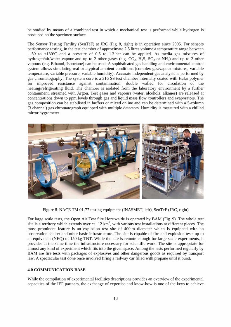
be studied by means of a combined test in which a mechanical test is performed while hydrogen is produced on the specimen surface.
The Sensor Testing Facility (SenTeF) at JRC (Fig. 8, right) is in operation since 2005. For sensors performance testing, in the test chamber of approximate 2.5 litres volume a temperature range between - 50 to +130ºC and a pressure of 0.5 to 1.3 bar can be applied. As media gas mixtures of hydrogen/air/water vapour and up to 2 other gases (e.g. CO2, H2S, SO2 or NH3) and up to 2 other vapours (e.g. Ethanol, Isooctane) can be used. A sophisticated gas handling and environmental control system allows simulating real or atypical ambient conditions (complex gas/vapour mixtures, variable temperature, variable pressure, variable humidity). Accurate independent gas analysis is performed by gas chromatography. The system core is a 316 SS test chamber internally coated with Halar polymer for improved resistance against contamination, double walled for circulation of the heating/refrigerating fluid. The chamber is isolated from the laboratory environment by a further containment, streamed with Argon. Test gases and vapours (water, alcohols, alkanes) are released at concentrations down to ppm levels through gas and liquid mass flow controllers and evaporators. The gas composition can be stabilised in buffers or mixed online and can be determined with a 5-column (3 channel) gas chromatograph equipped with multiple detectors. Humidity is measured with a chilled mirror hygrometer.
Figure 8. NACE TM 01-77 testing equipment (INASMET, left), SenTeF (JRC, right)
For large scale tests, the Open Air Test Site Horstwalde is operated by BAM (Fig. 9). The whole test site is a territory which extends over ca. 12 km2, with various test installations at different places. The most prominent feature is an explosion test site of 400 m diameter which is equipped with an observation shelter and other basic infrastructure. The site is capable of fire and explosion tests up to an equivalent (NEQ) of 150 kg TNT. While the site is remote enough for large scale experiments, it provides at the same time the infrastructure necessary for scientific work. The site is appropriate for almost any kind of experiment which fits into the given space. Among the tests performed regularly by BAM are fire tests with packages of explosives and other dangerous goods as required by transport law. A spectacular test done once involved firing a railway car filled with propane until it burst.
4.0 COMMUNICATION BASE
While the compilation of experimental facilities descriptions provides an overview of the experimental capacities of the IEF partners, the exchange of expertise and know-how is one of the keys to achieve
13
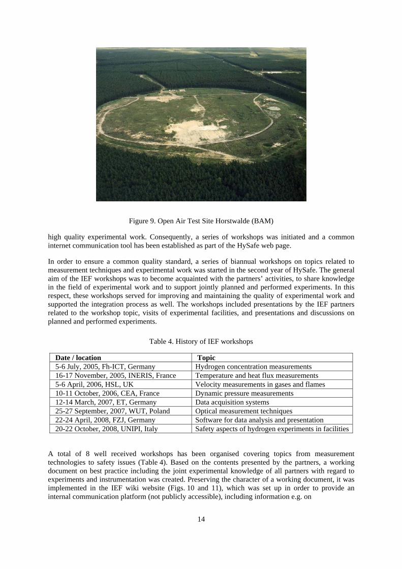
Figure 9. Open Air Test Site Horstwalde (BAM)
high quality experimental work. Consequently, a series of workshops was initiated and a common internet communication tool has been established as part of the HySafe web page.
In order to ensure a common quality standard, a series of biannual workshops on topics related to measurement techniques and experimental work was started in the second year of HySafe. The general aim of the IEF workshops was to become acquainted with the partners’ activities, to share knowledge in the field of experimental work and to support jointly planned and performed experiments. In this respect, these workshops served for improving and maintaining the quality of experimental work and supported the integration process as well. The workshops included presentations by the IEF partners related to the workshop topic, visits of experimental facilities, and presentations and discussions on planned and performed experiments.
Table 4. History of IEF workshops
Date / location Topic 5-6 July, 2005, Fh-ICT, Germany Hydrogen concentration measurements 16-17 November, 2005, INERIS, France Temperature and heat flux measurements 5-6 April, 2006, HSL, UK Velocity measurements in gases and flames 10-11 October, 2006, CEA, France Dynamic pressure measurements 12-14 March, 2007, ET, Germany Data acquisition systems 25-27 September, 2007, WUT, Poland Optical measurement techniques 22-24 April, 2008, FZJ, Germany Software for data analysis and presentation 20-22 October, 2008, UNIPI, Italy Safety aspects of hydrogen experiments in facilities
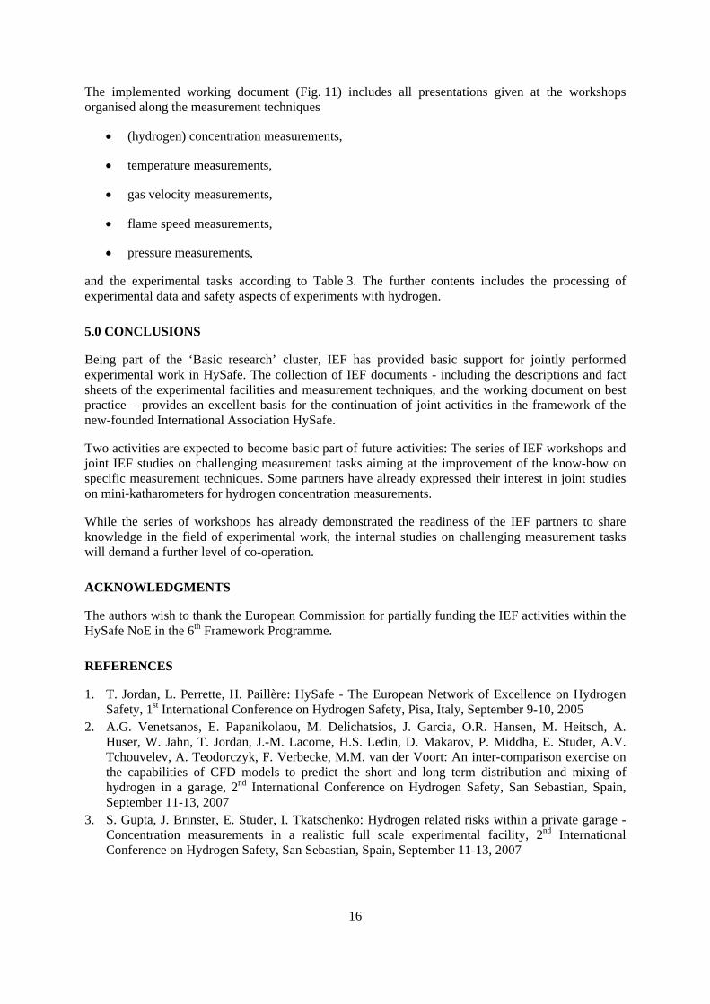
A total of 8 well received workshops has been organised covering topics from measurement technologies to safety issues (Table 4). Based on the contents presented by the partners, a working document on best practice including the joint experimental knowledge of all partners with regard to experiments and instrumentation was created. Preserving the character of a working document, it was implemented in the IEF wiki website (Figs. 10 and 11), which was set up in order to provide an internal communication platform (not publicly accessible), including information e.g. on
14
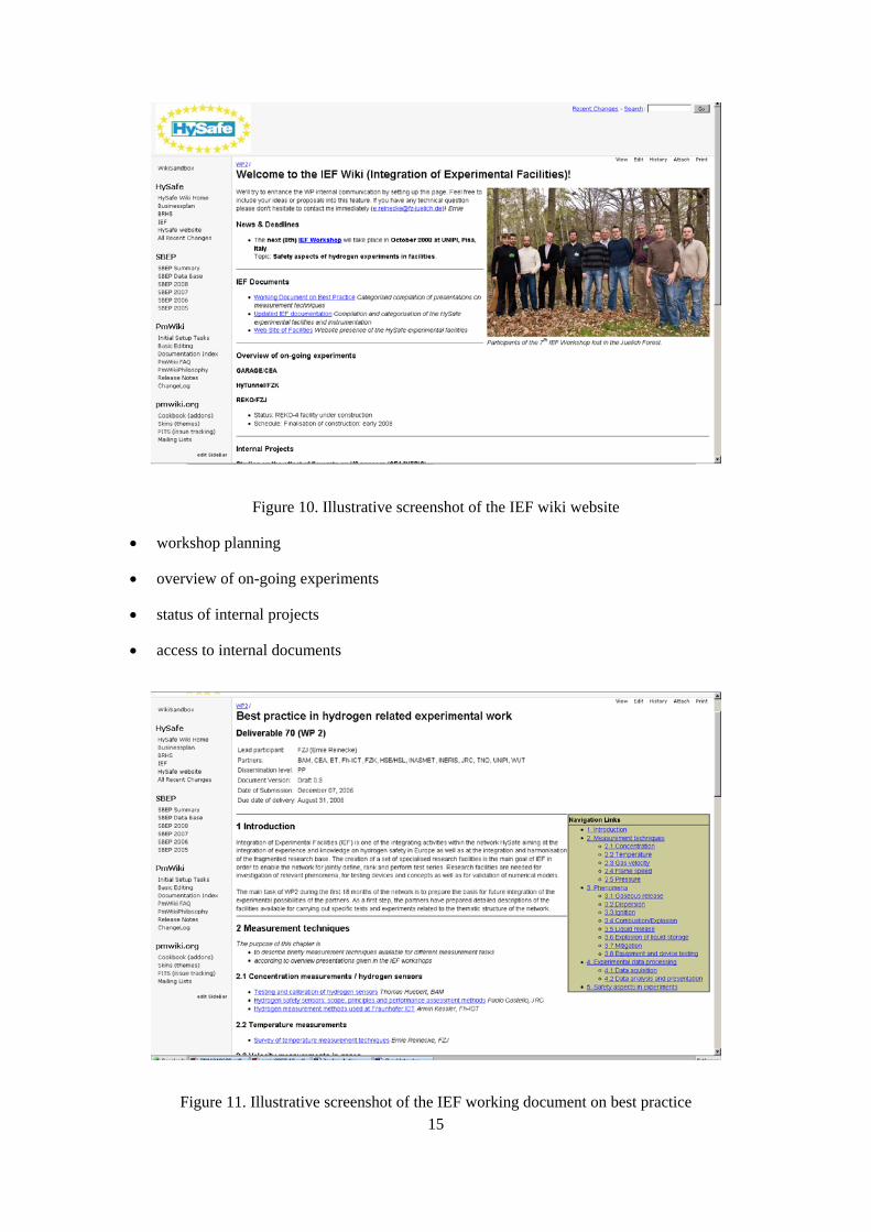
Figure 10. Illustrative screenshot of the IEF wiki website
• workshop planning
• overview of on-going experiments
• status of internal projects
• access to internal documents
Figure 11. Illustrative screenshot of the IEF working document on best practice 15
16
The implemented working document (Fig. 11) includes all presentations given at the workshops organised along the measurement techniques
• (hydrogen) concentration measurements,
• temperature measurements,
• gas velocity measurements,
• flame speed measurements,
• pressure measurements,
and the experimental tasks according to Table 3. The further contents includes the processing of experimental data and safety aspects of experiments with hydrogen.
5.0 CONCLUSIONS
Being part of the ‘Basic research’ cluster, IEF has provided basic support for jointly performed experimental work in HySafe. The collection of IEF documents - including the descriptions and fact sheets of the experimental facilities and measurement techniques, and the working document on best practice – provides an excellent basis for the continuation of joint activities in the framework of the new-founded International Association HySafe.
Two activities are expected to become basic part of future activities: The series of IEF workshops and joint IEF studies on challenging measurement tasks aiming at the improvement of the know-how on specific measurement techniques. Some partners have already expressed their interest in joint studies on mini-katharometers for hydrogen concentration measurements.
While the series of workshops has already demonstrated the readiness of the IEF partners to share knowledge in the field of experimental work, the internal studies on challenging measurement tasks will demand a further level of co-operation.
ACKNOWLEDGMENTS
The authors wish to thank the European Commission for partially funding the IEF activities within the HySafe NoE in the 6th Framework Programme.
REFERENCES
1. T. Jordan, L. Perrette, H. Paillère: HySafe - The European Network of Excellence on Hydrogen Safety, 1st International Conference on Hydrogen Safety, Pisa, Italy, September 9-10, 2005
2. A.G. Venetsanos, E. Papanikolaou, M. Delichatsios, J. Garcia, O.R. Hansen, M. Heitsch, A. Huser, W. Jahn, T. Jordan, J.-M. Lacome, H.S. Ledin, D. Makarov, P. Middha, E. Studer, A.V. Tchouvelev, A. Teodorczyk, F. Verbecke, M.M. van der Voort: An inter-comparison exercise on the capabilities of CFD models to predict the short and long term distribution and mixing of hydrogen in a garage, 2nd International Conference on Hydrogen Safety, San Sebastian, Spain, September 11-13, 2007
3. S. Gupta, J. Brinster, E. Studer, I. Tkatschenko: Hydrogen related risks within a private garage - Concentration measurements in a realistic full scale experimental facility, 2nd International Conference on Hydrogen Safety, San Sebastian, Spain, September 11-13, 2007