Embed Size (px)
Citation preview
1 BROOKHAVEN SCIENCE ASSOCIATES
NSLS-II Experimental Floor Space and Beamline Infrastructure.
Andy BroadbentExperimental Facilities Division, NSLS-II
NSLS-II Informational Meeting for Beamline DevelopmentApril 14, 2010
2 BROOKHAVEN SCIENCE ASSOCIATES
Summary
• Experimental Floor Space and Standard Beamline Territory• Standard Radiation Enclosures• Front Ends• Standard Utilities Pack for Beamlines• Laboratory and Office Buildings (LOBs).
3 BROOKHAVEN SCIENCE ASSOCIATES
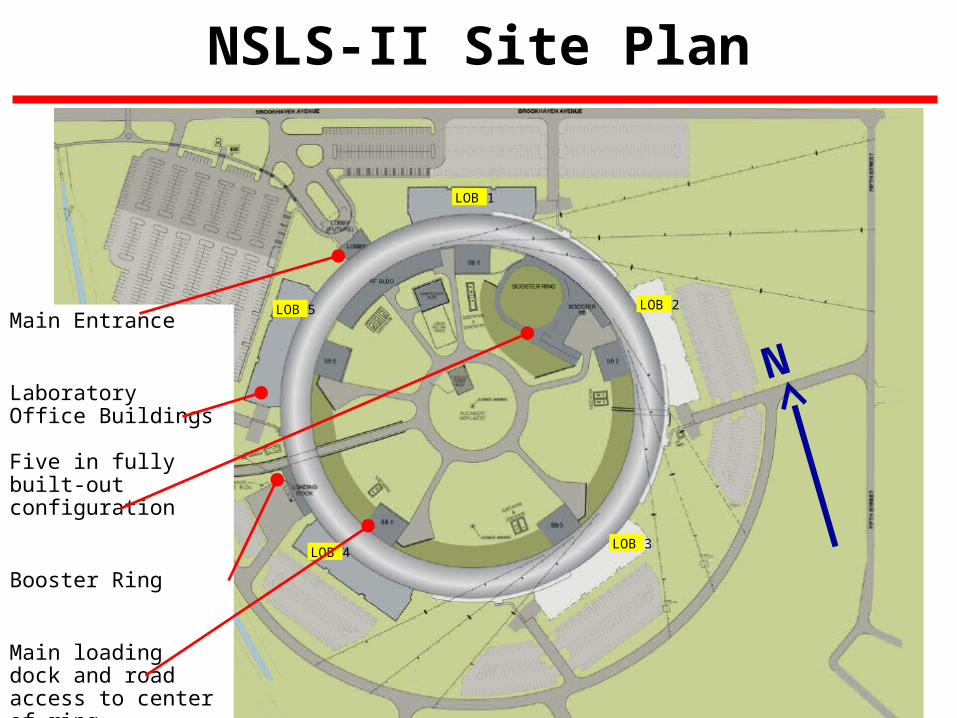
NSLS-II Site Plan
LOB 1
LOB 2
LOB 3LOB 4
LOB 5
NMain Entrance
Laboratory Office Buildings Five in fully built-out configuration
Booster Ring
Main loading dock and road access to center of ring
Service Building- one per pentant
4 BROOKHAVEN SCIENCE ASSOCIATES
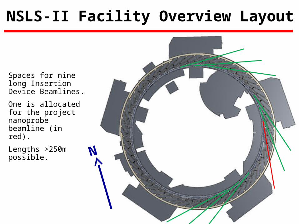
NSLS-II Facility Overview Layout
Spaces for nine long Insertion Device Beamlines.
One is allocated for the project nanoprobe beamline (in red).
Lengths >250m possible.
N

5 BROOKHAVEN SCIENCE ASSOCIATES
Alternative vibration
isolation joint position
Normal vibration
isolation joint position
Extra 10’ of floor length
…. gives about 6m of extra beamline length on experiment floor.
Beamlines passing outside the facility require a low level “bypass”, this gives the opportunity for extra floor space
6’9” typ

6 BROOKHAVEN SCIENCE ASSOCIATES
Standard and Extended Length Floor Areas
• Additional 10’ radial floor distance (gives additional 6m on beamline length) where by-pass corridors are located.• Approximately 30% of periphery of facility
• The LOBs are also designed to act as a corridor for the experimental floor giving another area of extended length beamlines.• Approximately 50% of periphery of facility.
• The standard length floor at 16 beamline positions.• The extended length floor is available to 44 beamlines.

7 BROOKHAVEN SCIENCE ASSOCIATES
NSLS-II Experimental Floor Layout (Standard)
Beamline Ratchet wall Standard floor edge
Odd cell: LBS ID 25.468m 67.135m
Odd cell: TPW 24.826m 64.834m
Odd cell: BM 24.471m 64.742m
Even cell: HBS ID 26.717m 67.379m
Even cell: TPW 23.543m 63.586m
Even cell: BM 23.189m 63.487m

8 BROOKHAVEN SCIENCE ASSOCIATES
NSLS-II Experimental Floor Layout (Extended)
Beamline Ratchet wall Extended floor edge
Odd cell: LBS ID 25.468m 73.490m
Odd cell: TPW 24.826m 71.220m
Odd cell: BM 24.471m 71.127m
Even cell: HBS ID 26.717m 73.713m
Even cell: TPW 23.543m 69.940m
Even cell: BM 23.189m 69.874m
Refer to Drawing LT-XF-CF-1008 for full dimensions of all beamlines.

9 BROOKHAVEN SCIENCE ASSOCIATES
NSLS-II Experimental Floor Layout
• Very standard floor access aisles• Need access to ID FEs only (30 doors)• Tunnel floor is 200mm higher than experimental floor
(beam height at 1200mm, and 1400mm on experimental floor).
• Sector floor layout designed to optimized space.
• Safety emergency egress requirements• Strong preference to include a duck-under route wherever possible to
meet the 75’ “common path of travel” in BCNYS regulations.• Some alternatives if a duck under is not compatible with the scientific
requirements

10 BROOKHAVEN SCIENCE ASSOCIATES
NSLS-II IXS Beamline Hutch Layout
Ratchet wall
First Optics Enclosure (FOE)
End Station 1
End Station 2
High beta straight area with extended floor. Note that building over the egress aisle is justified only by scientific requirements and requires express written approval. The aisle will be relocated taking a portion of the BM/TPW sector.
Egress aisle(relocated with permission)
Duck under route(relocated)

11 BROOKHAVEN SCIENCE ASSOCIATES
Hard X-ray Nanoprobe Remote Station

12 BROOKHAVEN SCIENCE ASSOCIATES
Two Possible IR Beamline Layouts
BM-A Dipole Magnet
BM-B Dipole Magnet
Storage Ring Tunnel
Experimental Floor
IR beamline passes under BM FE, through ratchet wall to unusable ID floor area*.
IR beamline passes over useable BM beamline
* There are three unusable ID ports, (2 x RF and 1 x injection)

13 BROOKHAVEN SCIENCE ASSOCIATES
NSLS-II Project Beamline Location Constraints and Preferences.
Beamline Straight Extended exp floor
Long beamline
Location Requirements Options Location Preferences
IXS Hi-beta
Y N Non damping wiggler straight
4,10,12.
ELS capability (at least with shorter adjacent straights even if not with three fold symmetry).
HXN Low-beta Y Not adjacent to LOB loading docks.
27,3,9.
Optimized location with low vibration levels
CHX Low-beta Y N Extended experimental floor to allow emergency duck-under between FOE and ES.
5,11,17,23,29.
CSX Low-beta Y N Located away from sources of draughts (exposed optics and end station).
5,11,17,23,29.
Straight 23 is between RF straights and therefore likely to have convenient “parking” space for additional end stations.
SRX Low-beta canted
N N Does not require extended experimental floor.
21 Ideally near to an IR beamline position. Close to bio village.
XPD Hi-beta
Y N DW source 18,28.
At beneficial occupancy there is a long duration between the floor at straight 28, and straight 18 being available.

14 BROOKHAVEN SCIENCE ASSOCIATES
Hutch Shielding Thicknesses
Source FOE Shielding * End station shielding *
IVU 18/6/50 Pb 6/3/6 Fe
EPU 18/5/50 Pb 6/3/6 Fe
DW 18/10/50 Pb 4/3/4 Pb
BM 3(Fe)/3(Fe)/30(Pb) 2/2/2 Fe
TPW 5/4/30 Pb 3/2/3 Fe
* Shielding given is for sidewalls/roof/downstream wall, in mm.
See also document “Guidelines for NSLS-II Beamlines and Front End Radiation Shielding Design” by Job and Casey, May 2008 for explanation and assumption.
http://groups.nsls2.bnl.gov/eshqa/Lists/Announcements/Attachments/13/shielding%20guidelines%20for%20beamlines.pdf

16 BROOKHAVEN SCIENCE ASSOCIATES
Typical Front End Configuration
Ratchet wall collimator
Dual safety shutters
X-Y slits
XBPM2
XBPM1
Collimator
Fixed aperture mask
Slow gate valve
Bending magnet photon shutter
Photon shutter
Slow gate valve
Beam direction
Relatively Minor Variants for Canted Configuration and Damping Wiggler Beamlines.
17 BROOKHAVEN SCIENCE ASSOCIATES
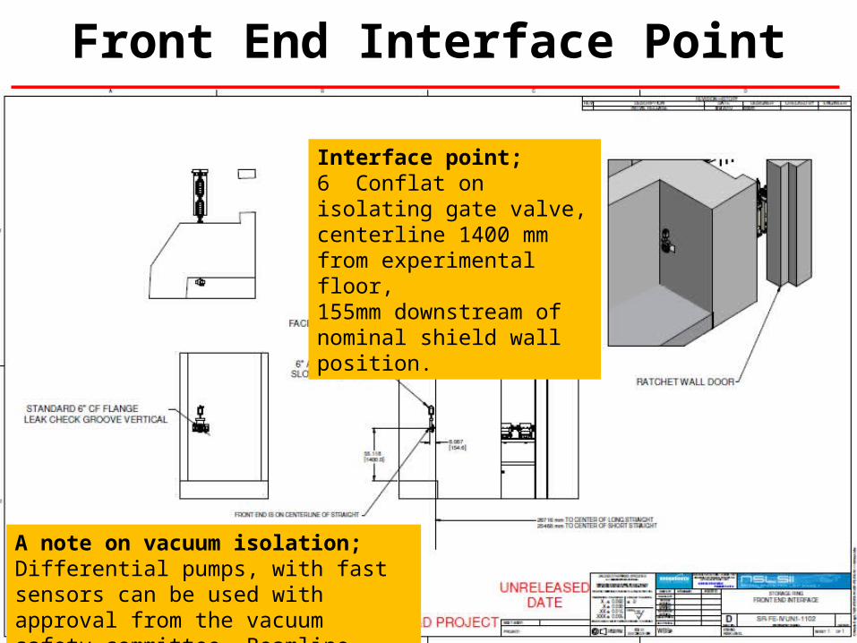
Front End Interface Point
Interface point;6” Conflat on isolating gate valve,centerline 1400 mm from experimental floor,155mm downstream of nominal shield wall position.
A note on vacuum isolation;Differential pumps, with fast sensors can be used with approval from the vacuum safety committee. Beamline isolation windows are not mandatory.

18 BROOKHAVEN SCIENCE ASSOCIATES
Beamline Standard Utilities Pack
• Requirements, Specifications and Interfaces document defines:• The beamline interfaces to conventional
facilities and accelerator systems;• The beamline utilities at the point of usage.
• Extensively reviewed and approved.• Reference document for design of beamlines;• Key specifications available in the Beamline
Design Guide*.
* copies will be available on request within ~two months, the information within is NOT required for the proposal.

19 BROOKHAVEN SCIENCE ASSOCIATES
Standard Utility Provisions - Electrical
• Each beamline has 2 x 30 kVA transformers for “sensitive” and “non-sensitive” power.
• Expected total electrical load <30kVA / beamline - at 50% transformer loading the hum noise will be negligible.
• Aim to dissipate 60% of electrical power into the chilled water system – helps maintain high temperature stability in experimental hall. Use water cooled racks, as used for accelerator PSUs.
• Small distributed UPS system to be included in beamline racks as required.

20 BROOKHAVEN SCIENCE ASSOCIATES
Standard Utility Provisions - Water
• High quality de-ionized Low conductivity Water (LCW) for cooling of accelerator components, front ends and beamline optics.• 12 GPM average, 15 GPM peak allowed per beamline.• Pressure is 100 psi nominal, 150 psi max.• 85F +/- 0.2 F (29.5+/-0.1C).• Piping comes through ratchet wall from SR tunnel into FOE.
• Chilled water for cooling of electronics racks and some end station equipment (eg furnaces, pumps, etc).• 3 GPM average, 6 GPM peak allowed per beamline.• Pressure is 100-120 psi nominal, 150 psi max.• 53F inlet temperature (20F temperature rise assumed at full rated flow and power removal).• Piping comes from roof of RF tunnel along top of beamline.

21 BROOKHAVEN SCIENCE ASSOCIATES
Standard Utility Provisions - Other
• Liquid nitrogen.• 40 Gal/hr average allowed per beamline (dominant usage from DCMs on DW beamlines).• Pressure is 30-45 psi nominal.• Piping around facility above the SR tunnel, with drops at each ID beamline.
• Gaseous nitrogen.• 20 cfm maximum allowed per beamline (main usage; purge gas and IR spectrometers etc).• Pressure is 30 psi nominal, 125 psi max.• Piping runs adjacent to LN2 system.
• Compressed air.• 10 cfm maximum (intermittent) allowed per beamline (main usage; valves, air skates etc).• Pressure is 75 psi nominal, 125 psi max.• Piping runs from SR tunnel through ratchet wall into FOE.
• Exhaust• Exhaust system above walkway allows HEPA filtered extraction to be linked in at any
beamline position.
24 BROOKHAVEN SCIENCE ASSOCIATES
Control Systems
• Aim to standardize much of the hardware, eg motion controls – currently being evaluated by BL controls working group.
• Wiring standards currently in development.
• EPICS for lower level accelerator and beamline controls.
• Expect to standardize on one or two User interface packages (work in progress).

25 BROOKHAVEN SCIENCE ASSOCIATES
Laboratory Office Buildings (LOBs)
• Based on detailed analysis and benchmarking with other facilities, an expanded LOB was specified to satisfy the needs of the NSLS-II community
• In general, 8 laboratories and 2 electronic work areas plus a machine shop will be available as shared facilities in each LOB to support user/staff activities at the neighboring beamlines :• 3 wet labs, 2 dry labs• 1 shared special purpose sample characterization lab• 1 mechanical assembly lab, 1 vacuum prep lab• 2 shared electronic work areas, 1 shared machine shop
• Adequate temporary storage space will be available for receiving and staging
• 75 office spaces will be available to support users & staff but 17 of these spaces accommodate 2, 4, or 6 people sharing them – Total occupancy 124

26 BROOKHAVEN SCIENCE ASSOCIATES
57 One person Offices6Two people Offices7Six people Offices3Wet Laboratories7Dry Laboratories8Machine Shop9Conference Rooms1 Loading/Storage Area
LOB First Floor Plan
Total = 38,000 gsf
Each Lab = 480 nsf
30 { {

27 BROOKHAVEN SCIENCE ASSOCIATES
Cross Section
Office Area Lab Area
Mechanical Penthouse

28 BROOKHAVEN SCIENCE ASSOCIATES
Exterior Perspective

29 BROOKHAVEN SCIENCE ASSOCIATES
Exterior Perspective
30 BROOKHAVEN SCIENCE ASSOCIATES
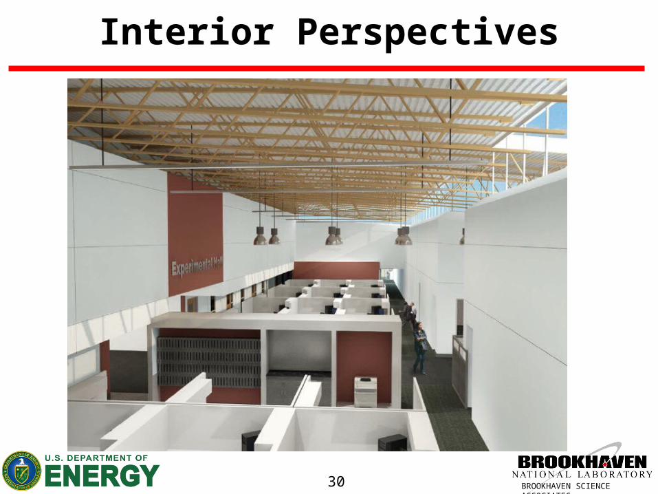
Interior Perspectives

31 BROOKHAVEN SCIENCE ASSOCIATES
Interior Perspectives

32 BROOKHAVEN SCIENCE ASSOCIATES
Laboratory Floor Plans

33 BROOKHAVEN SCIENCE ASSOCIATES
Wet Lab
34 BROOKHAVEN SCIENCE ASSOCIATES
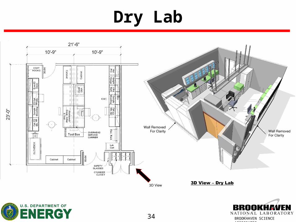
Dry Lab

35 BROOKHAVEN SCIENCE ASSOCIATES
Initial Dry Lab Equipment ListOptical microscope for sample mounting & inspectionSample mounting area with small tools (e.g. HP, capillaries)Ultrasonic bathHot plate / ovenEvacuated or electric desiccators for sample storageHeight gauge on flat baseGlove box for sample prep under controlled atmosphereWorkbench for equipment setup / testingElectronic rackElectronics setup/repair workbench w/ voltmeter & pulse gen.Instrument vice and magnifierDigital and analog oscillascopesSoldering station w/ roller wire suppliesMotor test station w/ rack & PCClean assembly area for sample/optics vacuum chamberGas cylindersTurbomolecular pump station cartRoller table / cartRheometerRadioactive source containerSEM for sample fiducial marking & measurementHigh-power confocal microscope for sample prealignmentUV-Vis spectrometer with PCSolid-state / area detector set-up / testing
Initial list produced for space estimation purposes only.LOB build package includes benches, sinks, cupboards , safety shower, etc.
Removable / specialist lab equipment will be part of separate budget.

36 BROOKHAVEN SCIENCE ASSOCIATES
Initial Wet Lab Equipment ListRefrigerators for sample storageDeep refrigeratorsHigh precision balanceCentrifugepH probe with calibrated solutionsMicrotome for sample sectioning/preparationTemperature ovenChemical hood with sinkCorrosion resistent workbenchHazardous / flammable chemical storageChemical storageHazardous gas cabinetsPlunge freezerFreeze-dryerGlassware cabinet / shelfLN2 dewarDI water generator with small sinkEye wash / safety shower90-day chemical waste storageHazardous specimen requiring quarantine of fume-hoodSafety PPE shelf

37 BROOKHAVEN SCIENCE ASSOCIATES
Initial Machine Shop Equipment List
LatheMillBand sawDrill pressSander/grinderHand tool workbench with standard viseToolboxCabinets for machining tools (drill bits, etc.)Shop vacuumWash sinkFire extinguisherTrash can for machining wasteSafety PPE shelf
The five machine shops around NSLS-II will be expected to specialize to some extent – for example one of the five may have a larger milling machine.
38 BROOKHAVEN SCIENCE ASSOCIATES
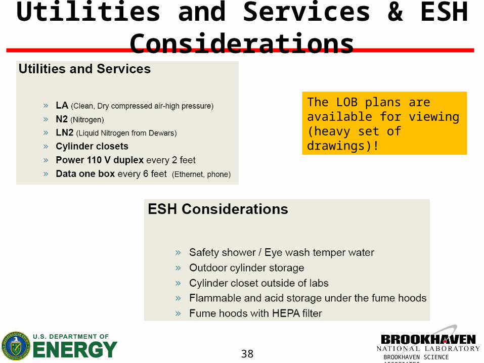
Utilities and Services & ESH Considerations
The LOB plans are available for viewing (heavy set of drawings)!

39 BROOKHAVEN SCIENCE ASSOCIATES
QUESTIONS?