Embed Size (px)
Citation preview

AN INSTRUMENT FOR DETECTING DELAMINATION
IN CONCRETE BRIDGE DECKS
William M, Moore Associate Research Engineer
Gilbert Swift Research Instrumentation Engineer
and
Lionel J. Milberger Research Associate
Research Report Number 130-4 A Study of Reinforced Concrete Bridge Deck Deterioration:
Diagnosis, Treatment and Repair Research Study Number 2-18-68~130
Sponsored by
The Texas Highway Department In Cooperation with the
U o S ·0 Department of Transportation Federal Highway Administration
Bureau of Public Roads
August, 1970
TEXAS TRANSPORTATION INSTITUTE Texas A&M University
College Stati~n, Texas

ABSTRACT
This report describes a research effort directed toward finding a
means for detecting delamination, one of the more serious forms ~~ de-
terioration found in concrete bridge decks. Its describes (a) ne of
the methods employed for delamination detection, (b) the development
of the basic components required for automatic detection, and (c) the
completed instrument resulting from the research. The detecting unit
is in the form of a push cart, roughly the size and shape of a power
lawP mm,rer. Also included in the report is an evaluation of the devic~'
ace< shed by measuring specially constructed test slabs and numerous
in-service bridges. The evaluation tests indicate that the instrument
provides a practical and effective means for the routine detection of
bridge deck delamination by maintenance personnel. The instrument was
found to be insensitive to deck texture, or to thin asphaltic surfac
ing layers. The operation of the detector is not impaired by rolling
speeds of up to about ten miles per huu1.~.

T A B L E 0 F C 0 N T E N T S
LIST OF FIGURES . .
INTRODUCTION • .
EXISTING DETECTION TECHNIQUES •
1.
2 0
3.
4.
So
6.
7.
DEVELOPMENT OF BASIC COMPONENTS .
DELAMINATION DETECTOR UNIT ..
EVALUATION. ,
CONCLUSIONS
IMPLEMENTATION STATEMENT.
8. REFERENCES 0 • • • • • • • •
i
Page
ii
1
4
9
15
20
27
28
29

LIST OF FIGURES
Figure Page
1. Deterioration of Delaminated Bridge Deck • • 3
2. Bridge Deck Tapping Hammer • 5
3. Kansas Delamination Detection Device • 7
4. Nichols' Sonic Testing Device. 8
5. Delamination Detection Tapping Device .• . . . 10
6. Delamination Detection Acoustic Receiver. 12
7. Block Diagram of Signal Conditioner • 14
8. Delamination Detector in Operation. . 16
'9. Delamination Detector, Rear View •• 17
10. Delamination Detector Disassembled •• 18
11. Delamination Detection Test Slabs . . . . . 21
12. Typical Delamination Detector Records • 22
13. Multiple Path Records From One Bridge Deck. . 24
14. Typical Coring Results ..•••••• 25
ii

1. INTRODUCTION
This is a progress report of Phase 1 of a research study entitled
11 A Study of Reinforced Concrete Bridge Deck Deterioration: Diagnosis,
Treatment and Repair 11, being conducted by the Texas Transportatiort
Institute and sponsored by the Texas Highway Department and the Bureau
of Public Roads. The specific objective of this phase of the research
is the development of methods to evaluate the extent of deterioration in
bridge decks.
In the early part of this study it was decided jointly by represen
tatives of the Texas Highway Department and the Texas Transportation
Institute, that although many factors are required to characterize the
extent of deterioration in a bridge deck; there are two defects that
could be considered of paramount importance, They are (a) delamination
(a separation of the original slab into two or more approximately hori
zontal layers) and (b) poor quality concrete. These two factors were
singled out because it was felt that most structural damage to deterio
rating bridge decks resulted from one or the other or both of these
defects, Other considerations in the selection of these factors are that
damage to structures caused by them is often not visible until signifi
cant deterioration is present, and also that the known techniques for
their detection are slow and tedious. Thus, the major emphasis of this
research has been directed toward methods for detecting delamination and
also detecting poor quality concrete. This report is being written to
describe the research efforts directed toward the former, the detection
of delamination.
-1-

Delamination is sometimes referred to as horizontal cracking. It
oc~urs frequently at the elevation of the reinforcing steel and most
often at the upper level of reinforcing steel. Delaminated areas may
range in size from a f.ew square inches t0 seven\1 square yards. After
initial delamination occurs, additional rapid deterioration of the deck
under the combined influence of weather and traffic may be expected to
follow. Figure 1 illustrates a delaminated bridge deck in the last
stages of deterioration.
This report describes an instrument that has been developed specif
ically to detect delamination. It also includes an evaluation of the
device 1 accomplished by measuring specially constructed test slabs and
numerous in-service bridges. All evaluation tests that have been con
d•J.-::ted indicate that the instrument will detect delamination in bridge
decks and that its routine use is practical.
-2-

f.
FIGURE 1: A typical delaminated area of a bridge deck in the last stages of deterioration.
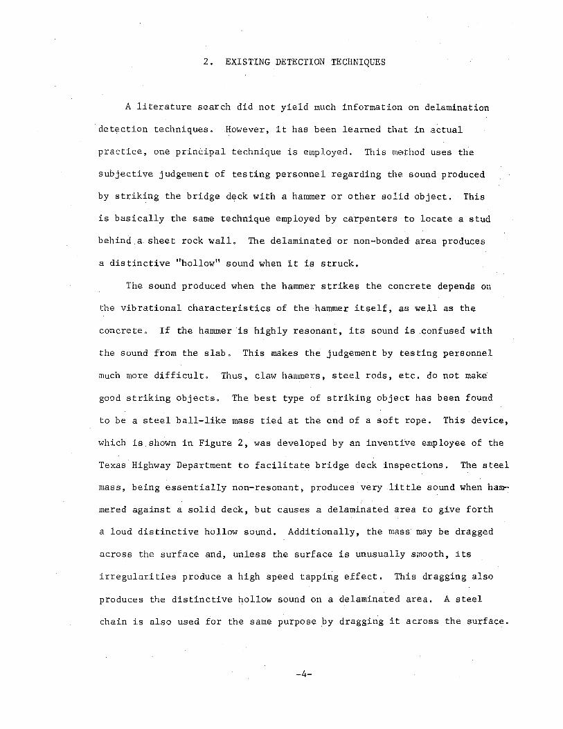
2. EXISTING DETECTION TECHNIQUES
A literature search did not yield much information on delamination
detection techniques. However, it has been learned that in actual
practice, one principal technique is employed. This method uses the
subjective judgement of testing personnel regarding the sound produced
by striking the bridge deck with a hammer or other solid object. This
is basically the same technique employed by carpenters to locate a stud
behind a. sheet rock wall, The delaminated or non-bonded area produces
a distinctive "hollow" sound when it is struck.
The sound produced when the hammer strikes the concrete depends on
the vibrational characteristics of the hammer itself, as well as the
concrete. If the hammer is highly resonant, its sound is confused with
the sound from the slab. This makes the judgement by testing personnel
much more difficult. Thus, claw hammers, steel rods, etc. do not make
good striking objects, The best type of striking object has been found
to be a steel ball-like mass tied at the end of a soft rope. This device,
which is_shown in Figure 2, was developed by an inventive employee of the
Texas Highway Department to facilitate bridge deck inspections. The steel
mass, being essentially non-resonant, produces very little sound when ham
mered against a solid deck, but causes a delaminated area to give forth
a loud distinctive hollow sound. Additionally, the mass may be dragged
across the surface and, unless the surface is unusually smooth, its
irregularities produce a high speed tapping effect. This dragging also
produces the distinctive hollow sound on a delaminated area. A steel
chain is also used for the same purpose by dragging it across the surface.
-4-

FIGURE 2: Tapping mass used for locating delaminated concrete in bridge decks. This simple but effective device was developed by an employee of the Texas Highway Department.

Another device, which was developed several years ago by the
Research Department of the Kansas State Highway Commission to detect
delamination in bridge decks, is shown in Figure 3. In operat~on
this device strikes the deck at regular intervals with small wooden
blocks, allowing the operator to make a subjective judfgement as to
the type of sound produced. It was described in some detail by
Bertram D. Tallamy Associates (l). Although this device is capable
of surveying large areas rather quickly, the wooden blocks are some
what resonant which_in turn impairs the operator's judgement.
Another mechanism designed for the detection of delamination is
illustrated in Figure 4. This device, invented by Nichols (~) was
designed to detect the lack of bond in honeycomb metal panels. Basi
cally the instrument consists of a metal pegged wheel with an acoustical
pickup on the handle. As the device is rolled across a metal panel,
the lack of b~ond between the honeycomb and the metal panel is said to
be indicated by the output signal from the acoustical pickup.
-6-

FIGURE 3: Delamination detection device developed by the Research Department of the Kansas State Highway Commission.

uand ope<ated 9on~c test~ng device ~nvented bJ N~cho~s to detect de~aminat~on in honeycomb
metal panels (~)·

3. DEVELOPMENT OF BASIC COMPONENTS
After one considers the existing techniques for delamination
detection, the device invented by Nichols appears to offer one sub•
stantial advantage - it does not require the subjective judgement of
testing personnel. Thus, an instrument of this general type was tried.
The attempt was not successful. The mechanism generated a large amount
of signal when operated on a solid deck, and hence gave a poor con.trast
between solid and delaminated areas. Nevertheless, after investigating
and trying several other alternatives, the.researchers concluded that
the acoustic response to a tapping-type stimulus had substantial advan
tages 'over the other possible approaches.
The basic concept of an automatic device using the acoustic response
to a tapping-type stimulus leads to requirements for the following three
basic components: (1) a tapping device, (2) an acoustic receiver (e.g.
a microphone) and (3) a signal conditioner to distinguish and produce
the desired output. Many variations have been tried. The most success
ful of the variations are described below and they have been incorporated
into the delamination detector unit treated in Section 4.
Tapping Device
The tapping device that is used is shown in Figure 5. It consists of
a plunger which is oscillated vertically by a pair of solenoids. The
plunger strikes a sharp blow at each end of its stroke, At one end, the
blow is sufficiently violent to cause the tapping mechanism with its
rigid steel-rimmed wheel to overcome gravity and break contact with the
-9-
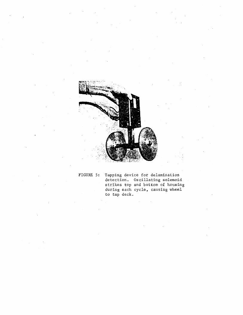
FIGURE 5: Tapping device for delamination detection. Oscillating solenoid strikes top and bottom of housing during each cycle, causing wheel to tap deck.
concrete surface. Thus, the tapping assembly chatters against the bridge
deck s~rface and excites the characteristic vibration of any delaminated
area with which it comes in contact. The magnitude of the tapping is
kept to a non-destructive level. However, the wheel of the tapper leaves 'f.
a visible white track consisting of fine powdered material along the
traverse. This minor crushing of surface grains is similar to that which
would result from dragging the tip of a steel bar along the deck.
Acoustic Receiver
The development of a suitable acoustic receiver was unquestionably
the most difficult task. Early in the research, it was found that
receiving the signal through air with a conventional microphone presented I
a hopeless case. Ambient noises due to traffic, rolling, etc. were con-
fused with the received signal and made it impossible to distinguish re-
libaly between solid and delaminated concrete.
The fir.st successful receiver consisted of a piezoelectric crystal
receiver mounted on the axle of a solid aluminum wheel. A rubber tread
was glued to the aluminum wheel to minimize the noise producing effect
of deck texture. Although this receiver was able to distinguish between
solid and delaminated concrete while rolling across the deck, the distinc-
tion was not as clear as desirabie.
Tile mos,t satisfactory of the various designs tried is shown in
Figure 6. It consists of an immersion proof microphone (pressure trans-
ducer) mounted internally near the bottom of a soft rubber tire. Acoustic
coupling is obtained by filling the tire with a mixture of water and
ethylene-glycol. This receiver has almost no sensitivity to ambient noises
-11-

FIGURE 6: The rolling acoustic receiver developed for delamination detection contains a pressure sensitive crystal microphone inside the liquidfilled tire. The lower photograph shows the receiver partially disassembled.

or surface texture. It maintains excellent acoustic coupling while
rolling, and it produces a relatively strong output signaL
Signal Conditioner
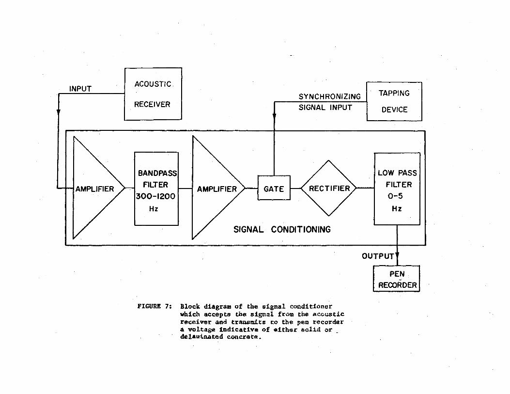
The signal conditioner which accepts the electrical signals pro.f
duced by the rolling receiver and processes them for recording is dia-
gra~med in Figure 7. The distinction between delaminated and solid
~oncrete is enhanced by filtering and by time-interval gating. Specif-
ically, the distinction between delaminated and non-delaminated zones is
enhanced by selecting only those frequency components of the received
sound which fall between 300 and 1200 Hz. Also, the distinction is
further improved by accepting only that portion of the received sig-'
nal which occurs during the first 3 milliseconds after a tap has been
made. Taps, which are produced 60 times per second, occur at inter-
vals of 16.7 milliseconds: thus, there is a relatively short interval
during which the recording system is allowed to accept signals from the
~olling receivers,
The final signal conditioning is accomplished by rectifying and
integrating the signal over a period of approximately 1/4 second. This
p~~vides a rapidly responding voltage suitable for display on a pen-
recorder. Delaminated areas extending over one or two square feet ordi-
narily produce responses exceeding 1 volt. Smaller areas result in lesser
responses which can be interpreted usefully down to about 0 .OS volt.
Unwanted responses, due to rolling over rough surfaces and to other dis-
turb'3.nces are substantially below 0.05 valL
-13-
INPUT ACOUSTIC
RECEIVER
BANDPASS
FILTER
300-1200
Hz
SYNCHRONIZING
SIGNAL INPUT
GATE
SIGNAL CONDITIONING
FIGURE 7: Block diagram of the signal conditioner which accepts the signal from the acoustic receiver and transmits to the pea recorder 4 voltage indicative of either 5olid or _ delaminated concreta.
TAPPING
DEVICE
LOW PASS
FILTER
0-5
Hz
OUTPUT
PEN
RECORDER

4. DELAMINATION DETECTOR UNIT
The basic components developed in this study and described in
the previous section have been incorporated into the delamination
detector shown in Figure 8, This unit, in the form of a mobilefcart,
is roughly the size and shape of a push type power lawn.mower •. It is
equipped with two rolling acoustic receivers spaced twelve inches
apart, and with two tapping wheels spaced six inches apart and centered
between the receivers (Figure 9). Since the unit detects delamination
only when a receiver and a tapping wheel are simultaneously over a
delaminated area, the unit surveys two three-inch-wide parallel paths
that are six inches apart.
The unit consists of several separable components, each of suitable
size and weight for one-man lifting and stowage in an automobile trunk.
They are (a) a main frame which houses the tapping device and rolling
receivers, (b) a two channel pen recorder, (c) a control unit which con
tains two signal conditioning channels, and (d) a power pack which contains
a small storage battery and an inverter for 120 volt AC. The disassembled
unit is shown in Figure 10. Assembly or disassembly of the unit on site
takes less than one minute.
The two-pen recorder uses four-inch-wide chart paper divided for
two pen records. The drive for the chart paper is geared directly to one
of the cart support wheels; thus, the lengthwise chart scale represents
fon,"ard distance traversed. One minor chart division represents 0.5 foot
of traverse. On solid concrete the pens remain at a stable small value
-15-

FIGURE 8: Delamination detector in operation.

FIGURE 9: A rear view of the delamination detector. The acoustic receivers are spaced 12 inches apart and the tapping wheels, 6 inches apart. The outer wheels support the cart.

' ' ' --,' ."", \ ": . ,' ',· ·-:, 'r , ,., ~ ' ... . '
FIGURE 10: Delamination detector disassembled and stowed in an automobile trunk. From left to right: power pack, control unit, recorder and main frame.

(near zero on the transverse scale) and excursions larger than about
2 minor chart divisions from this low value are indicative of delam
ination. Although there are several control knobs on the recorder
(gain, pen intensity, zero adjustment, etc), it is normally not nec
essary to adjust any of them for operation.
The operation controls consist of two on-off switches on the
control unit. One is the main power switch and the other is the
tapper switch.
After charging, the power pack will provide sufficient power to
operate the detector continuously for more than ten hours. For routine
operations, it is charged each night for the next day's operation.
-19-

5. EVALUATION
In the early phase of the research, the two rectangular test slabs
that are shown in Figure 11 were constructed to simulate bridge deck
delamination, One of these slabs is about one-half inc~' thick and the
other is slightly less than two inches thick. Prior to placing these
slabs, the foundation concrete was prepared to cause bonding to occur
on half of each slab and delamination on the other half. This was
accomplished by carefully cleaning the foundation concrete and allowing
it to dry. Then, immediately prior to placing the fresh concrete, a
neat cement paste was applied to the foundation for the bonded halves
and a fine layer of kaolinite dust was applied for the delaminated halves.
The desired results of delamination and bonding were achieved and these
test slabs were used for the primary instrumentation development work.
After the delamination detector was completed, a field evaluation
was initiated, consisting of surveying twenty-six bridge decks suspected
of containing delaminations. Significant amounts of delaminated areas
were found in about half of these bridges which were scattered over a
wide area in Texas.
Results obtained from traverses about eighty feet long made on two
typical bridges are illustrated in Figure 12. The upper record is from
a bridge in which no delaminations could be detected and the lower record
is from another bridge that contains many delaminations (any signal lar
ger than two minor chart divisions is an indication of delamination). The
lower record also illustrates that the two channels are independent. De
laminations were encountered in the left survey path at points where they
-20-
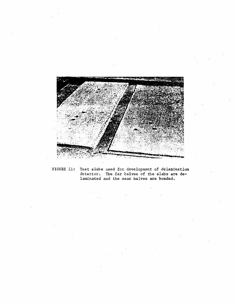
FIGURE 11: Test slabs used for development of delamination detector. The far halves of the slabs are delaminated and the near halves are bonded.
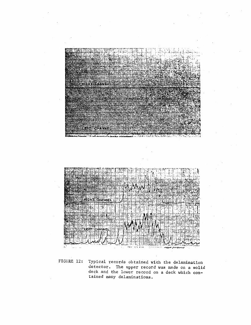
FIGURE 12: Typical records obtained with the delamination detector. The upper record was made on a solid deck and the lower record on a deck which contained many delaminations.

were absent in the.right path" At these points the right edge of the
delaminations must lie between the two survey paths.
If several parallel traverses are made on a deck, the detector
recordings can be used to prepare a map of the delaminated areas. Upon
transferring the locations where delaminations are indicate~ on each
traverse to a properly scaled plan view of the deck, the delaminated areas
may be outlined, Closely spaced traverses permit drawing a highly detailed
map, Typical multiple path records are illustrated in Figure 13.
The ability of the delamination detector to distinguish delaminated
from solid concrete was verified by coring six different bridges. On
each bridge one core was taken at a location where delamination was not
indicated and another at a location where delamination was indicated.
Agreement was perfect. No evidence of delamination or horizontal crack
ing could be found upon examination of the walls of the core holes at the
six locations where delamination was not indicated. Delamination was
obvious upon examination of each of the other six holes. Typical results
are illustrated in Figure 14. The depth of the horizontal cracks at the
six delaminated areas varied from one-half to three and one-half inches.
Several of the twenty-six bridge decks surveyed were badly spalled
and therefore, had a very rough surface texture. The instrument's
operation was not impaired by the rough texture. Two of the six decks
cored had thin layers of asphaltic surfacing, one a seal coat and the
other a half-inch asphaltic concrete overlay. Since the instrument per
formed well on these bridges it is concluded that the detector is insen
sitive to deck texture and to layers of asphaltic surfacing less than
approximately one-half inch in thickness. The effect of thicker asphaltic
-23-

~: i ~ ' ---F-----+---·~ --.~ -- ~---- i-~:---·---!1·-
: H:- --- . ~ - ~~ . . ~ - ----· :.J_: ~.
A
FIGURE 13: Multiple path records made on a bridge deck. Most of the delaminations found in this deck were in the middle two slabs.

FIGURE 14: Typical results found by coring at a location where delamination was indicated by the unit.

6. CONCLUSIONS
From the results of this study the following conclusions appear
warranted:
1. The delamination detector developed in this phase of the
research study provides an effective means for determin
ing the extent of delamination in concrete bridge decks.
2o The detector is easy to operate and practical for routine
use.
3. The detector is insensitive to deck texture or thin
asphaltic surfacing layers.
4. The operation of the instrument is not impaired at rolling
speeds up to about ten miles per hour.
-27-

7. IMPLEMENTATION STATEMENT .
The results reported here clearly indicate that multiple-path,
automatic delamination detection is practical and possible. A detec~
.f
tor can be designed and constructed that will survey a lane of a
bridge at one time. Using modern data acquisition and reduction tech-
niques, a map showing the delaminated areas of the deck can be au~o
matically produced with such a detector.
The researchers believe that the present detector should be used
in an extensive investigation to determine the growth pattern and un
cover the causes of bridge deck delamination.
-28-
8. REFERENCES
1. Tallamy, Bertram, D. and Associates, "Evaluation of Methods of Replacement of Deteriorated Concrete in Structures", National Cooperative Highway Research Program Report 1, Highway Research Board, National Academy of Sciences, National Research Council, Washington, D. C., 1964.
2. Nichols, D. R., "Sonic Testing Device", United States Patent No. 3,361,225, January 2, 1968.
-29-