Embed Size (px)
Citation preview
For the installer
ecoMAX 613/2 E
ecoMAX 618/2 E
ecoMAX 622/2 E
ecoMAX 635 E
ecoMAX 824/2 E
ecoMAX 828/2 E
ecoMAX 835 E
GB
Instructions for installation and servicing ecoMAX
Wall hung room sealed fan assisted condensing boilers
83 41 77_12 GB04.04.qxd 22.09.2004 12:34 Uhr Seite 1
2
Table of contents
Instructions for installation and servicing ecoMAX2
1 Introduction . . . . . . . . . . . . . . . . . . . . . . . . 41.1 Introduction . . . . . . . . . . . . . . . . . . . . . . . . . . . . 41.2 General notes . . . . . . . . . . . . . . . . . . . . . . . . . . . 41.3 EC designation . . . . . . . . . . . . . . . . . . . . . . . . . . 4
2 Boiler specification . . . . . . . . . . . . . . . . . . . 52.1 Technical data . . . . . . . . . . . . . . . . . . . . . . . . . . 62.2 Dimensions . . . . . . . . . . . . . . . . . . . . . . . . . . . . . 62.3 Boiler connections . . . . . . . . . . . . . . . . . . . . . . . 72.4 Scale drawing and fitting dimensions . . . . . . . 72.5 Functional diagrams . . . . . . . . . . . . . . . . . . . . . 82.6 Design . . . . . . . . . . . . . . . . . . . . . . . . . . . . . . . . . 92.7 Identification plate . . . . . . . . . . . . . . . . . . . . . . . 10
3 General requirements . . . . . . . . . . . . . . . . . 103.1 Preliminary remarks . . . . . . . . . . . . . . . . . . . . . 103.2 Related documents . . . . . . . . . . . . . . . . . . . . . . 103.3 Contents included with boiler (ecoMAX 800) . 113.4 Contents included with boiler (ecoMAX 600) . 113.5 Boiler location . . . . . . . . . . . . . . . . . . . . . . . . . . 123.6 Gas supply . . . . . . . . . . . . . . . . . . . . . . . . . . . . . 123.7 Flue system . . . . . . . . . . . . . . . . . . . . . . . . . . . . . 123.7.1 Standard 100 mm flue system . . . . . . . . . . . . . 123.7.2 Optional 125 mm flue system (ecoMAX 635, 835) 123.8 Flue termination . . . . . . . . . . . . . . . . . . . . . . . . 133.9 Air supply . . . . . . . . . . . . . . . . . . . . . . . . . . . . . . 143.9.1 Cupboard or compartment ventilation . . . . . . 143.10 Electrical supply . . . . . . . . . . . . . . . . . . . . . . . . . 143.11 Guide to system requirements . . . . . . . . . . . . . 143.11.1 Water circulation system . . . . . . . . . . . . . . . . . . 143.11.2 Filling and make up . . . . . . . . . . . . . . . . . . . . . . 143.11.3 Pressure relief valve . . . . . . . . . . . . . . . . . . . . . 143.11.4 Pressure gauge . . . . . . . . . . . . . . . . . . . . . . . . . 153.11.5 Expansion vessel . . . . . . . . . . . . . . . . . . . . . . . . 153.12 Pump specifications . . . . . . . . . . . . . . . . . . . . . 153.12.1 Circulating pump . . . . . . . . . . . . . . . . . . . . . . . . 153.12.2 System by–pass . . . . . . . . . . . . . . . . . . . . . . . . . 153.12.3 Venting . . . . . . . . . . . . . . . . . . . . . . . . . . . . . . . . 153.13 Condensate trap . . . . . . . . . . . . . . . . . . . . . . . . . 15
4 Boiler installation sequence . . . . . . . . . . . . 164.1 General . . . . . . . . . . . . . . . . . . . . . . . . . . . . . . . . 164.1.1 Select position of boiler . . . . . . . . . . . . . . . . . . 164.1.2 Unpack the boiler . . . . . . . . . . . . . . . . . . . . . . . . 164.1.3 Using boiler template . . . . . . . . . . . . . . . . . . . . 164.2 Rear flue exit . . . . . . . . . . . . . . . . . . . . . . . . . . . 174.3 Other flue options . . . . . . . . . . . . . . . . . . . . . . . 174.4 Fitting the boiler hanging bracket . . . . . . . . . . 174.5 Install the flue system . . . . . . . . . . . . . . . . . . . . 174.6 Fitting the boiler . . . . . . . . . . . . . . . . . . . . . . . . 184.7 Removing the front case . . . . . . . . . . . . . . . . . . 184.8 Cold water mains inlet and hot water outlet
(ecoMAX 800) . . . . . . . . . . . . . . . . . . . . . . . . . . 184.9 Gas supply . . . . . . . . . . . . . . . . . . . . . . . . . . . . . 194.10 Central heating flow and return pipework . . . 194.11 Pressure Relief Valve (ecoMAX 600) . . . . . . . . 204.12 Pressure Relief Valve (ecoMAX 800) . . . . . . . . 204.13 Condensate drain . . . . . . . . . . . . . . . . . . . . . . . . 21
4.14 Connection to a VANTAGE cylinder (ecoMAX 600) . . . . . . . . . . . . . . . . . . . . . . . . . . 21
4.15 Connect the flue system to the boiler . . . . . . . 214.16 Electrical installation . . . . . . . . . . . . . . . . . . . . . 224.16.1 General requirements . . . . . . . . . . . . . . . . . . . . 224.16.2 Connection to the main supply . . . . . . . . . . . . 224.16.3 Electronic board layout . . . . . . . . . . . . . . . . . . . 234.16.4 Connection details for programmable
thermostats . . . . . . . . . . . . . . . . . . . . . . . . . . . . 294.17 Controls (ecoMAX 800) . . . . . . . . . . . . . . . . . . . 294.17.1 External electrical controls . . . . . . . . . . . . . . . . 294.17.2 Connection of external controls . . . . . . . . . . . . 294.17.3 Connection details for programmable room
thermostats . . . . . . . . . . . . . . . . . . . . . . . . . . . . 294.17.4 Connection details for time switch . . . . . . . . . 304.17.5 Connection details for external time
switches and boiler terminal strip . . . . . . . . . . 314.17.6 Vaillant optional plug in timer accessories . . . 314.18 Controls (ecoMAX 600) . . . . . . . . . . . . . . . . . . . 314.18.1 External electrical controls . . . . . . . . . . . . . . . . 314.18.2 Connection of external electrical controls . . . 314.18.3 Connection details using an external
wiring centre . . . . . . . . . . . . . . . . . . . . . . . . . . . 314.19 Thermostatic radiator valves . . . . . . . . . . . . . . 314.20 Frost protection . . . . . . . . . . . . . . . . . . . . . . . . . 314.21 Circulating pump . . . . . . . . . . . . . . . . . . . . . . . . 314.22 Anti–cycling ‘economiser’ control . . . . . . . . . . 314.23 Automatic pump spin control (APS) . . . . . . . . 31
5 Commissioning part I . . . . . . . . . . . . . . . . . 345.1 Preliminary electrical checks . . . . . . . . . . . . . . 345.2 Gas supply . . . . . . . . . . . . . . . . . . . . . . . . . . . . . 345.3 Cold water supply (ecoMAX 800) . . . . . . . . . . 345.4 Filling the heating system
(ecoMAX 800) . . . . . . . . . . . . . . . . . . . . . . . . . . 345.5 Initial system flush (”Cold”) . . . . . . . . . . . . . . . 345.6 Filling the heating system
(ecoMAX 600) . . . . . . . . . . . . . . . . . . . . . . . . . . . 345.7 Initial system flush (”Cold”) . . . . . . . . . . . . . . . 345.8 Filling condensate trap . . . . . . . . . . . . . . . . . . . 345.9 Adjusting pump speed . . . . . . . . . . . . . . . . . . . . 355.9.1 ecoMAX 613/2, 618/2, 622/2, 824/2, 828/2 . . . 355.9.2 ecoMAX 635, 835 . . . . . . . . . . . . . . . . . . . . . . . 355.10 Checking the gas supply settings . . . . . . . . . . . 375.10.1 Factory–adjusted gas settings . . . . . . . . . . . . . 375.10.2 Gas inlet working pressure . . . . . . . . . . . . . . . . 375.10.3 Check gas rate . . . . . . . . . . . . . . . . . . . . . . . . . . 375.11 Refitting the case . . . . . . . . . . . . . . . . . . . . . . . . 385.12 Adjusting the central heating output
(range rating) . . . . . . . . . . . . . . . . . . . . . . . . . . . 38
6 Functional checks (commissioning part II) . 396.1 Functional checks . . . . . . . . . . . . . . . . . . . . . . . 396.1.1 Procedure . . . . . . . . . . . . . . . . . . . . . . . . . . . . . . 396.1.2 Hot–water supply (ecoMAX 800) . . . . . . . . . . . 406.1.3 Heating system . . . . . . . . . . . . . . . . . . . . . . . . . 406.1.4 Final system flush (”Hot”) . . . . . . . . . . . . . . . . . 406.1.5 Handing over to the user . . . . . . . . . . . . . . . . . 40
83 41 77_12 GB04.04.qxd 22.09.2004 12:34 Uhr Seite 2
3
Table of contents
Instructions for installation and servicing ecoMAX 3
7 Servicing . . . . . . . . . . . . . . . . . . . . . . . . . . . 417.1 Inspection and maintenance . . . . . . . . . . . . . . . 417.2 Initial inspection . . . . . . . . . . . . . . . . . . . . . . . . 417.2.1 Removing the compact thermal module . . . . . 417.2.2 Inspect main heat exchanger . . . . . . . . . . . . . . 427.2.3 Inspect burner . . . . . . . . . . . . . . . . . . . . . . . . . . 427.2.4 Refitting the compact thermal module . . . . . . 437.2.5 Cleaning the condensate trap . . . . . . . . . . . . . 437.2.6 Check expansion vessel . . . . . . . . . . . . . . . . . . . 437.3 Recommissioning the boiler . . . . . . . . . . . . . . . 447.4 Test . . . . . . . . . . . . . . . . . . . . . . . . . . . . . . . . . . . 44
8 Troubleshooting . . . . . . . . . . . . . . . . . . . . . . 448.1 Logical fault finding procedure . . . . . . . . . . . . 448.1.1 Status mode . . . . . . . . . . . . . . . . . . . . . . . . . . . . 448.1.2 Diagnosis mode . . . . . . . . . . . . . . . . . . . . . . . . . 468.1.3 Fault codes . . . . . . . . . . . . . . . . . . . . . . . . . . . . . 488.1.4 Fault memory . . . . . . . . . . . . . . . . . . . . . . . . . . . 488.2 Test programs . . . . . . . . . . . . . . . . . . . . . . . . . . 50
9 Parts replacement . . . . . . . . . . . . . . . . . . . 519.1 Safety instructions . . . . . . . . . . . . . . . . . . . . . . . 519.1.1 Initial preparation . . . . . . . . . . . . . . . . . . . . . . . 519.1.2 Removal of burner assembly . . . . . . . . . . . . . . 519.2 Replacement of burner . . . . . . . . . . . . . . . . . . . 519.3 Replacement of fan . . . . . . . . . . . . . . . . . . . . . . 519.4 Replacement of gas valve . . . . . . . . . . . . . . . . . 529.5 Replacement of central heating
expansion vessel . . . . . . . . . . . . . . . . . . . . . . . . 529.6 Replacement of main heat exchanger . . . . . . . 539.7 Replacement of the electronic control board . 549.8 Check CO2 content and adjust if necessary
(air–ratio adjustment) . . . . . . . . . . . . . . . . . . . . 54
10 Recycling and eventual scrapping . . . . . . . . 5510.1 The appliance . . . . . . . . . . . . . . . . . . . . . . . . . . . 5510.2 Packing . . . . . . . . . . . . . . . . . . . . . . . . . . . . . . . . 55
83 41 77_12 GB04.04.qxd 22.09.2004 12:34 Uhr Seite 3
4
1 Introduction
Instructions for installation and servicing ecoMAX4
1 Introduction
1.1 Introduction
Note: This boiler must be installed and serviced by acompetent person in accordance with the GasSafety (Installation and Use) Regulations 1998.In the UK ‘CORGI’ registered installers undertake the work to a safe and satisfactory stan-dard.
ecoMAX 800 rangeThe ecoMAX 800 range is a fully automatic, wall moun-ted, room sealed condensing (high efficiency) combinati-on boiler for central heating and domestic hot water.Domestic hot water is supplied directly from the boiler,without requiring a copper cylinder, cold water tank,feed and expansion tank and associated pipework.Domestic hot water has priority over central heating.The ecoMAX 800 range consists of models with outputsfor domestic hot water of 23 kW, 28 kW and 35 kW. Allversions are available in natural gas. The 28 kW versionversion is also available in LPG.ecoMAX combination boilers incorporate a warmstartfacility that keeps the domestic hot water heat exchan-ger hot, providing an instantaneous delivery of domestichot water. The temperature in the domestic hot waterheat exchanger is limited by the boiler control systemand it is not necessary to install a scale reducer on thecold mains to the boiler. However, in exceptionally hardwater areas to prevent scale formation in the propertyhot water system pipework, a scale reducer may be fit-ted. The heating system can be filled using the built–infilling loop contained within the boiler.
ecoMAX 600 rangeThe ecoMAX 600 range is a fully automatic, wall moun-ted, room sealed condensing (high efficiency) systemboiler for central heating and domestic hot water (wherea separate indirect hot water storage cylinder is alsoincorporated in the system). The ecoMAX 600 rangeconsists of models with outputs of 13, 18, 22 and 35 kW.All ecoMAX 600 range boilers are available in NaturalGas. The 22 kW version is also available in LPG.
1.2 General NotesThe boilers have been designed for use with a sealedcentral heating system, and come fully tested andassembled with a built in circulating pump, expansionvessel and diverter valve (ecoMAX 800). The boilers areeasily sited on any internal wall and can be installed witheither a horizontal or vertical RSF (room sealed fan assi-sted) flue.The boilers use a standard flue system (100 mm outsidediameter) which allows flue lengths up to 8m (ecoMAX828/2, 613/2, 618/2 and 622/2) 7m (ecoMAX 824/2) and4 m (ecoMAX 635, 835). Flue extensions and additionalbends and elbows are available for the flue system toincrease the siting flexibility. If desired, an inhibitor maybe used in the system. Guidance on the use of inhibitorsis contained in these instructions.All boilers have a built in diagnostic system which indica-tes the operational status of the boiler. This feature pro-vides key information to aid commissioning and fault fin-ding. The data badge is fitted to the underside of theboiler. See text of General Requirements for installationrequirements or notes.
1.3 EC designation
ecoMAX boilers carry the ‘CE’ Mark. This demonstratesthat the boilers fulfil the essential requirements of theGas Appliance Directive (90/396/EEC) and the GasAppliance (Safety) Regulations 1992.The ‘CE’ Mark also demonstrates that the boilers complywith the requirements of the ElectromagneticCompatibility Directive (89/336/EEC), the Low VoltageDirective (72/23/EEC), the Boiler Efficiency Directive(92/42/EEC) and the Boiler (Efficiency) Regulations 1993.
Vaillant Ltd. support the Benchmark initiative. Within the information pack, you will find aBenchmark Log Book. It is very important thatthis is completed correctly at the time of instal-lation, commissioning and handover to the user.
83 41 77_12 GB04.04.qxd 22.09.2004 12:34 Uhr Seite 4
5
Boiler Specification 2
Instructions for installation and servicing ecoMAX 5
Boiler Specification 2
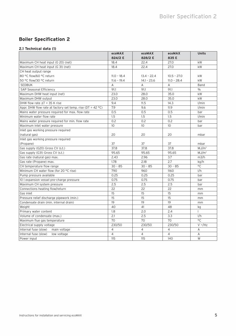
2.1 Technical data (1)ecoMAX ecoMAX ecoMAX Units
824/2 E 828/2 E 835 E
Maximum CH heat input (G 20) (net) 18.4 22.4 27.0 kW
Maximum CH heat input (G 31) (net) 18.4 22.4 27.0 kW
CH heat output range
80 °C flow/60 °C return 11.0 – 18.4 13.4 – 22.4 10.5 – 27.0 kW
50 °C flow/30 °C return 11.6 – 19.4 14.1 – 23.6 11.0 – 28.4 kW
SEDBUK A A A Band
SAP Seasonal Efficiency 91.1 91.1 91.1 %
Maximum DHW heat input (net) 23.0 28.0 35.0 kW
Maximum DHW output 23.0 28.0 35.0 kW
DHW flow rate ∆T = 35 K rise 9.4 11.5 14.3 l/min
Appr. DHW flow rate at factory set temp. rise (DT = 42 °C) 7.9 9.6 11.9 l/min
Mains water pressure required for max. flow rate 0.5 0.5 0.5 bar
Minimum water flow rate 1.5 1.5 1.5 l/min
Mains water pressure required for min. flow rate 0.2 0.2 0.2 bar
Maximum inlet water pressure 10 10 10 bar
Inlet gas working pressure required
(natural gas) 20 20 20 mbar
Inlet gas working pressure required
(Propane) 37 37 37 mbar
Gas supply (G20) Gross CV (s.t.) 37.8 37.8 37.8 MJ/m3
Gas supply (G31) Gross CV (s.t.) 95.65 95.65 95.65 MJ/m3
Gas rate (natural gas) max. 2.43 2.96 3.7 m3/h
Gas rate (Propane) max. 1.78 2.18 2.7 kg/h
CH temperature flow range 30 – 85 30 – 85 30 – 85 °C
Minimum CH water flow (for 20 °C rise) 790 960 1160 l/h
Pump pressure available 0.25 0.25 0.25 bar
10 l expansion vessel pre–charge pressure 0.75 0.75 0.75 bar
Maximum CH system pressure 2.5 2.5 2.5 bar
Connections heating flow/return 22 22 22 mm
Gas inlet 15 15 15 mm
Pressure relief discharge pipework (min.) 15 15 15 mm
Condensate drain (min. internal drain) 19 19 19 mm
Weight 40 41 48 kg
Primary water content 1.8 2.0 2.4 l
Volume of condensate (max.) 2.1 2.5 3.3 l/h
Maximum flue gas temperature 70 70 70 °C
Electrical supply voltage 230/50 230/50 230/50 V ~/Hz
Internal fuse (slow) main voltage 4 4 4 A
Internal fuse (slow) low voltage 4 4 4 A
Power input 115 115 140 W
83 41 77_12 GB04.04.qxd 22.09.2004 12:34 Uhr Seite 5
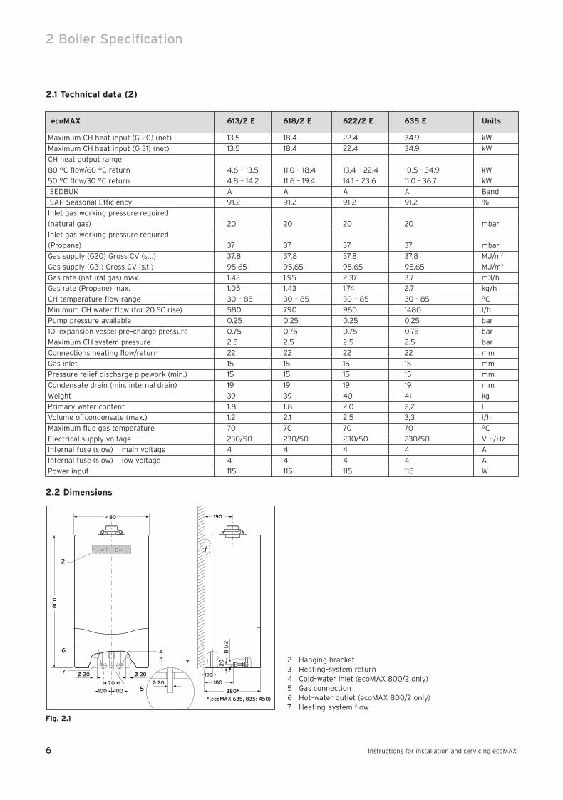
2.2 Dimensions
Fig. 2.1
2 Hanging bracket3 Heating–system return4 Cold–water inlet (ecoMAX 800/2 only)5 Gas connection6 Hot–water outlet (ecoMAX 800/2 only)7 Heating–system flow
70
190480
80
0
2
100
380*
7
Ø 20
100 100
Ø 20
5
3
7
Ø 20
20
R 1
/2
180
46
*(ecoMAX 635, 835: 450)
6
2 Boiler Specification
Instructions for installation and servicing ecoMAX6
2.1 Technical data (2)
ecoMAX 613/2 E 618/2 E 622/2 E 635 E Units
Maximum CH heat input (G 20) (net) 13.5 18.4 22.4 34.9 kW
Maximum CH heat input (G 31) (net) 13.5 18.4 22.4 34.9 kW
CH heat output range
80 °C flow/60 °C return 4.6 – 13.5 11.0 – 18.4 13.4 – 22.4 10.5 - 34.9 kW
50 °C flow/30 °C return 4.8 – 14.2 11.6 – 19.4 14.1 – 23.6 11.0 - 36.7 kW
SEDBUK A A A A Band
SAP Seasonal Efficiency 91.2 91.2 91.2 91.2 %
Inlet gas working pressure required
(natural gas) 20 20 20 20 mbar
Inlet gas working pressure required
(Propane) 37 37 37 37 mbar
Gas supply (G20) Gross CV (s.t.) 37.8 37.8 37.8 37.8 MJ/m3
Gas supply (G31) Gross CV (s.t.) 95.65 95.65 95.65 95.65 MJ/m3
Gas rate (natural gas) max. 1.43 1.95 2.37 3.7 m3/h
Gas rate (Propane) max. 1.05 1.43 1.74 2.7 kg/h
CH temperature flow range 30 – 85 30 – 85 30 – 85 30 - 85 °C
Minimum CH water flow (for 20 °C rise) 580 790 960 1480 l/h
Pump pressure available 0.25 0.25 0.25 0.25 bar
10l expansion vessel pre–charge pressure 0.75 0.75 0.75 0.75 bar
Maximum CH system pressure 2.5 2.5 2.5 2.5 bar
Connections heating flow/return 22 22 22 22 mm
Gas inlet 15 15 15 15 mm
Pressure relief discharge pipework (min.) 15 15 15 15 mm
Condensate drain (min. internal drain) 19 19 19 19 mm
Weight 39 39 40 41 kg
Primary water content 1.8 1.8 2.0 2,2 l
Volume of condensate (max.) 1.2 2.1 2.5 3,3 l/h
Maximum flue gas temperature 70 70 70 70 °C
Electrical supply voltage 230/50 230/50 230/50 230/50 V ~/Hz
Internal fuse (slow) main voltage 4 4 4 4 A
Internal fuse (slow) low voltage 4 4 4 4 A
Power input 115 115 115 115 W
83 41 77_12 GB04.04.qxd 22.09.2004 12:34 Uhr Seite 6
7
Boiler Specification 2
Instructions for installation and servicing ecoMAX 7
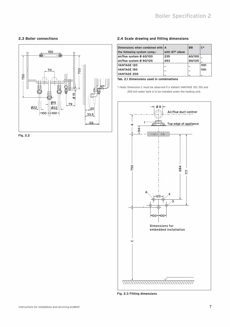
2.3 Boiler connections
Fig. 2.2
2.4 Scale drawing and fitting dimensions
Dimensions when combined with A ØB C*
the following system comp.: with 87° elbow
air/flue system Ø 60/100 235 60/100 _
air/flue system Ø 80/125 253 80/125 _
VANTAGE 120 _ _ 1101
VANTAGE 150 _ _ 1101
VANTAGE 200 _ _ _
Tab. 2.1 Dimensions used in combinations
*) Note: Dimension C must be observed if a Vaillant VANTAGE 120, 150 and
200 hot–water tank is to be installed under the heating unit.
Fig. 2.3 Fitting dimensions
94
1 Top edge of appliance
75
0C
A
Air/flue duct centrer
3
717
Dimensions forembedded installation
100 100
4
68
4
1206
Ø BØ22 Ø22 25
33.5100100
Ø 1
5
75
0
70
3
150
79
70
Ø15
113
83 41 77_12 GB04.04.qxd 22.09.2004 12:34 Uhr Seite 7
8
2 Boiler Specification
Instructions for installation and servicing ecoMAX8
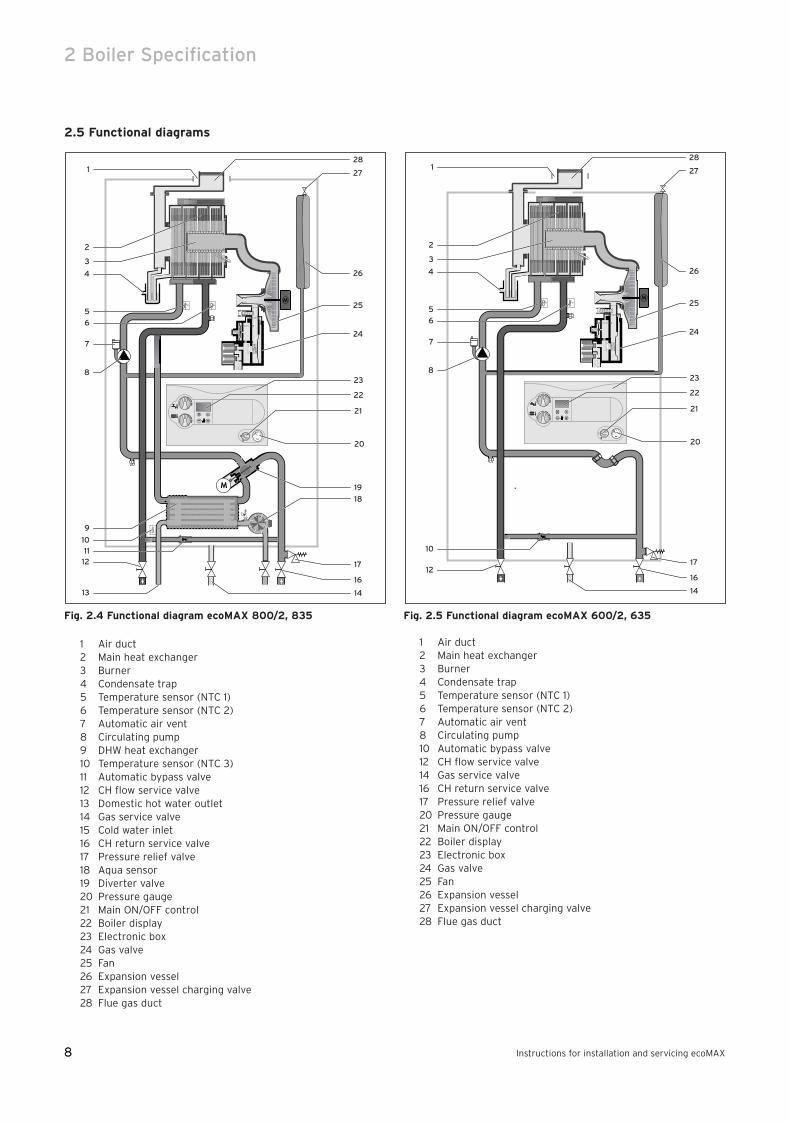
2.5 Functional diagrams
Fig. 2.4 Functional diagram ecoMAX 800/2, 835
1 Air duct2 Main heat exchanger3 Burner4 Condensate trap5 Temperature sensor (NTC 1)6 Temperature sensor (NTC 2)7 Automatic air vent8 Circulating pump9 DHW heat exchanger10 Temperature sensor (NTC 3)11 Automatic bypass valve12 CH flow service valve13 Domestic hot water outlet14 Gas service valve15 Cold water inlet16 CH return service valve17 Pressure relief valve18 Aqua sensor19 Diverter valve20 Pressure gauge21 Main ON/OFF control22 Boiler display23 Electronic box24 Gas valve25 Fan26 Expansion vessel27 Expansion vessel charging valve28 Flue gas duct
Fig. 2.5 Functional diagram ecoMAX 600/2, 635
1 Air duct2 Main heat exchanger3 Burner4 Condensate trap5 Temperature sensor (NTC 1)6 Temperature sensor (NTC 2)7 Automatic air vent8 Circulating pump10 Automatic bypass valve12 CH flow service valve14 Gas service valve16 CH return service valve17 Pressure relief valve20 Pressure gauge21 Main ON/OFF control22 Boiler display23 Electronic box24 Gas valve25 Fan26 Expansion vessel27 Expansion vessel charging valve28 Flue gas duct
28
27
26
2
4
5
6
7
8
10
12
3
1
25
24
22
23
21
20
17
16
14
28
27
26
2
4
5
6
7
8
9
10
1112
13
3
1
25
24
22
23
21
20
19
18
17
16
14
83 41 77_12 GB04.04.qxd 22.09.2004 12:34 Uhr Seite 8
9
Boiler Specification 2
Instructions for installation and servicing ecoMAX 9
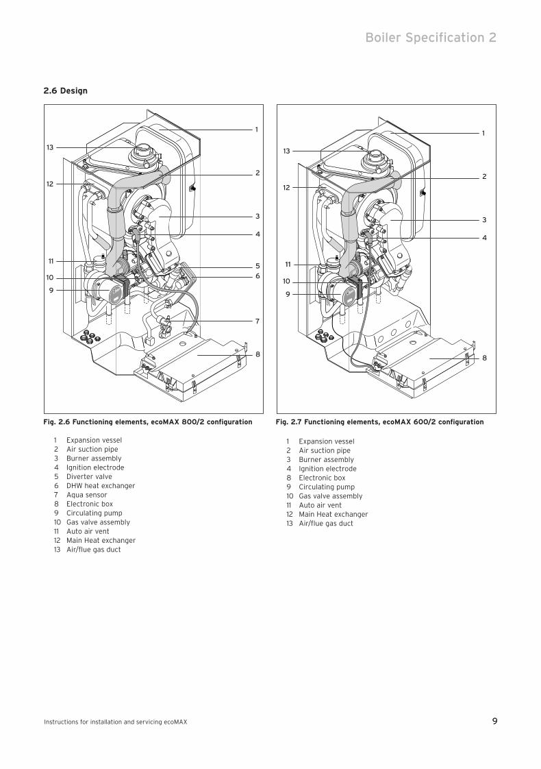
2.6 Design
Fig. 2.6 Functioning elements, ecoMAX 800/2 configuration
1 Expansion vessel2 Air suction pipe3 Burner assembly4 Ignition electrode5 Diverter valve6 DHW heat exchanger7 Aqua sensor8 Electronic box9 Circulating pump10 Gas valve assembly11 Auto air vent12 Main Heat exchanger13 Air/flue gas duct
Fig. 2.7 Functioning elements, ecoMAX 600/2 configuration
1 Expansion vessel2 Air suction pipe3 Burner assembly4 Ignition electrode8 Electronic box9 Circulating pump10 Gas valve assembly11 Auto air vent12 Main Heat exchanger13 Air/flue gas duct
1
2
3
4
8
9
10
11
12
13
1
2
3
4
6
5
7
8
9
10
11
12
13
83 41 77_12 GB04.04.qxd 22.09.2004 12:34 Uhr Seite 9
10
2 Boiler Specification3 General requirements
Instructions for installation and servicing ecoMAX10
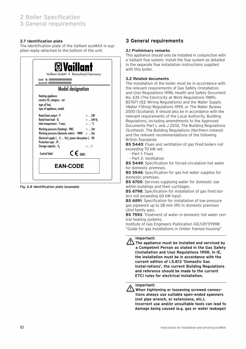
2.7 Identification plateThe identification plate of the Vaillant ecoMAX is sup-plied ready–attached to the bottom of the unit.
Fig. 2.8 Identification plate (example)
3 General requirements
3.1 Preliminary remarksThis appliance should only be installed in conjunction witha Vaillant flue system. Install the flue system as detailedin the separate flue installation instructions suppliedwith this boiler.
3.2 Related documentsThe installation of the boiler must be in accordance withthe relevant requirements of Gas Safety (Installation and Use) Regulations 1998, Health and Safety DocumentNo. 635 (The Electricity at Work Regulations 1989),BS7671 (IEE Wiring Regulations) and the Water Supply(Water Fitting) Regulations 1999, or The Water Bylaws2000 (Scotland). It should also be in accordance with therelevant requirements of the Local Authority, BuildingRegulations, including amendments to the ApprovedDocuments Part L and J 2002, The Building Regulations(Scotland). The Building Regulations (Northern Ireland)and the relevant recommendations of the followingBritish Standards:BS 5440: Flues and ventilation of gas fired boilers notexceeding 70 kW net:
– Part 1: Flues– Part 2: Ventilation
BS 5449: Specification for forced circulation hot waterfor domestic premises.BS 5546: Specification for gas hot water supplies fordomestic premises.BS 6700: Services supplying water for domestic usewithin buildings and their curtilages.BS 6798: Specification for installation of gas fired boi-lers not exceeding 60 kW input.BS 6891: Specification for installation of low pressuregas pipework up to 28 mm (R1) in domestic premises (2nd family gas).BS 7593: Treatment of water in domestic hot water cen-tral heating systems.Institute of Gas Engineers Publication IGE/UP/7/1998:”Guide for gas installations in timber framed housing”
Important: The appliance must be installed and serviced bya Competent Person as stated in the Gas Safety(Installation and Use) Regulations 1998. In IE,the installation must be in accordance with thecurrent edition of I.S.813 ‘Domestic GasInstal–lations’, the current Building Regulationsand reference should be made to the currentETCI rules for electrical installation.
Important:When tightening or loosening screwed connec-tions always use suitable open–ended spanners(not pipe wrench, or extensions, etc.). Incorrect use and/or unsuitable tools can lead todamage being caused (e.g. gas or water leakage)!
83 41 77_12 GB04.04.qxd 22.09.2004 12:34 Uhr Seite 10
11
General requirements 3
Instructions for installation and servicing ecoMAX 11
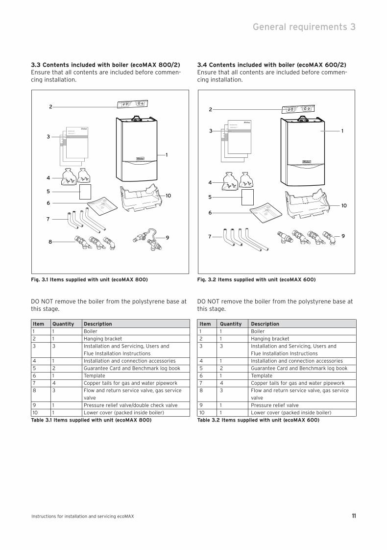
3.3 Contents included with boiler (ecoMAX 800/2)Ensure that all contents are included before commen-cing installation.
Fig. 3.1 Items supplied with unit (ecoMAX 800)
DO NOT remove the boiler from the polystyrene base atthis stage.
Item Quantity Description
1 1 Boiler
2 1 Hanging bracket
3 3 Installation and Servicing, Users and
Flue Installation Instructions
4 1 Installation and connection accessories
5 2 Guarantee Card and Benchmark log book
6 1 Template
7 4 Copper tails for gas and water pipework
8 3 Flow and return service valve, gas service
valve
9 1 Pressure relief valve/double check valve
10 1 Lower cover (packed inside boiler)
Table 3.1 Items supplied with unit (ecoMAX 800)
3.4 Contents included with boiler (ecoMAX 600/2)Ensure that all contents are included before commen-cing installation.
Fig. 3.2 Items supplied with unit (ecoMAX 600)
DO NOT remove the boiler from the polystyrene base atthis stage.
Item Quantity Description
1 1 Boiler
2 1 Hanging bracket
3 3 Installation and Servicing, Users and
Flue Installation Instructions
4 1 Installation and connection accessories
5 2 Guarantee Card and Benchmark log book
6 1 Template
7 4 Copper tails for gas and water pipework
8 3 Flow and return service valve, gas service
valve
9 1 Pressure relief valve
10 1 Lower cover (packed inside boiler)
Table 3.2 Items supplied with unit (ecoMAX 600)
4
5
2
6
7
3 1
10
9
10
9
1
4
5
2
6
7
8
3
83 41 77_12 GB04.04.qxd 22.09.2004 12:34 Uhr Seite 11
12
3 General requirements
Instructions for installation and servicing ecoMAX12
3.5 Boiler locationThe location chosen for the boiler must permit the provi-sion of a satisfactory flue termination. The location mustalso provide adequate space for servicing and air circu-lation around the boiler. The boiler may be installed inany room, although particular attention is drawn to therequirements of BS7671 (IEE Regulations), the electricalprovisions of the Building Standards (Scotland)Regula–tions, and in IE the current edition of IS813 andthe current ETCI rules, in respect of the installation of aboiler in a room containing a bath or shower.
Note: Where a room sealed boiler is installed in a roomcontaining a bath or shower, any electricalswitch or boiler control utilising mains electricityshould be so situated that it cannot be touchedby a person using the bath or shower.
Where the installation of the boiler will be in an unusuallocation, special procedures may be necessary and BS5546 and BS 6798 give detailed guidance on this aspect.The boiler must be mounted on a flat, vertical wall, whichmust be sufficiently robust to take the weight of the boi-ler. The boiler may be installed on a combustible wall,subject to the requirements of the Local Authorities andBuilding Regulations.A compartment used to enclose the boiler must be desi-gned and constructed specifically for this purpose. (Anexisting cupboard or compartment may be used provi-ded that it is modified for the purpose). Details of essen-tial features of cupboard/compartment design includingairing cupboard installations are given in BS 6798. If theboiler is to be fitted in a timber framed building, it shouldbe fitted in accordance with Institute of Gas EngineersPublication IGE/UP/7/1998 ”Guide for Gas Installation inTimber Framed Housing”.
3.6 Gas supplyThe gas supplier should ensure the availability of anade–quate supply of gas. A gas meter may only beconnected to the service pipe by the supplier of gas ortheir contrac–tor. An existing meter should be checked toensure that it is capable of passing the rate of gas supp-ly required.Installation pipes should be fitted in accordance with BS 6891. In IE the current edition of IS 813. Pipeworkfrom the meter to the boiler must be of an adequatesize. Do not use pipes of a smaller size than the boilergas connection (15 mm). The complete installation mustbe tested for soundness and purged as described in BS 6891.
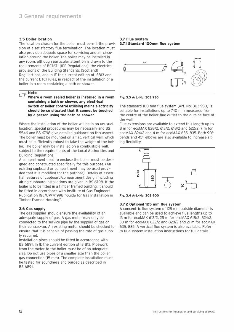
3.7 Flue system3.7.1 Standard 100mm flue system
Fig. 3.3 Art.–No. 303 930
The standard 100 mm flue system (Art. No. 303 930) issuitable for installations up to 740 mm measured fromthe centre of the boiler flue outlet to the outside face ofthe wall.Flue extensions are available to extend this length up to8 m for ecoMAX 828/2, 613/2, 618/2 and 622/2, 7 m forecoMAX 824/2 and 4 m for ecoMAX 635, 835. Both 90°bends and 45° elbows are also available to increase sit-ing flexibility.
Fig. 3.4 Art.–No. 303 900
3.7.2 Optional 125 mm flue systemA concentric flue system of 125 mm outside diameter isavailable and can be used to achieve flue lengths up to13 m for ecoMAX 613/2, 25 m for ecoMAX 618/2, 824/2,30 m for ecoMAX 622/2 and 828/2 and 21 m for ecoMAX635, 835. A vertical flue system is also available. Referto flue system installation instructions for full details.
153
0
88
0
70
800
40
13
83 41 77_12 GB04.04.qxd 22.09.2004 12:34 Uhr Seite 12
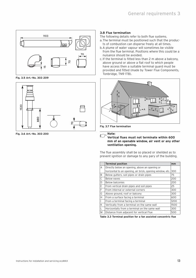
Fig. 3.5 Art.–No. 303 209
Fig. 3.6 Art.–No. 303 200
3.8 Flue terminationThe following details refer to both flue systems.a.The terminal must be positioned such that the produc-
ts of combustion can disperse freely at all times.b.A plume of water vapour will sometimes be visible
from the flue terminal. Positions where this could be anuisance should be avoided.
c. If the terminal is fitted less than 2 m above a balcony,above ground or above a flat roof to which peoplehave access then a suitable terminal guard must beprovided and fitted (made by Tower Flue Components,Tonbridge, TN9 1TB).
Fig. 3.7 Flue termination
Note:Vertical flues must not terminate within 600mm of an openable window, air vent or any otherventilation opening.
The flue assembly shall be so placed or sheilded as toprevent ignition or damage to any pary of the building.
Terminal position mm
A Directly below an opening, above an opening or
horizontal to an opening, air brick, opening window, etc. 300
B Below gutters, soil pipes or drain pipes 75
C Below eaves 200
D Below balconies 200
E From vertical drain pipes and soil pipes 25
F From internal or external corners 300
G Above ground, roof or balcony 300
H From a surface facing a terminal 600
I From a terminal facing a terminal 1200
K Vertically from a terminal on the same wall 1500
L Horizontally from a terminal on the same wall 300
M Distance from adjacent for vertical Flue 500
Table 3.3 Terminal position for a fan assisted concentric flue
A
BCD
A
G
H, IF J
B F M
L
LK
K
G
G
F F
E
A
A153
0
88
0
7070
1103
70
15
13
General requirements 3
Instructions for installation and servicing ecoMAX 13
83 41 77_12 GB04.04.qxd 22.09.2004 12:34 Uhr Seite 13
14
3 General requirements
Instructions for installation and servicing ecoMAX14
Note: In addition, the terminal should not be nearerthan 150 mm to an opening in the building fabricformed for the purpose of accommodating abuilt–in element such as a window.
BS 5440–1 It is recommended that the fanned flue termi-nal should be positioned as follows:a) at least 2m from an opening in the building directly
opposite, andb) so that the products of combustion are not directly
directed to discharge across a boundary.
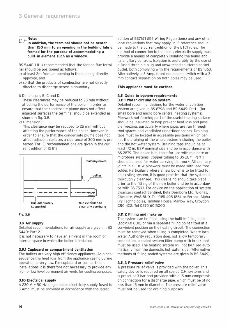
1) Dimensions B, C and D: These clearances may be reduced to 25 mm withoutaffecting the performance of the boiler. In order toensure that the condensate plume does not affectadjacent surfaces the terminal should be extended asshown in fig. 3.8.
2) Dimension F: This clearance may be reduced to 25 mm withoutaffecting the performance of the boiler. However, inorder to ensure that the condensate plume does notaffect adjacent surfaces a clearance of 300 mm is preferred. For IE, recommendations are given in the cur-rent edition of IS 813.
Fig. 3.8
3.9 Air supplyDetailed recommendations for air supply are given in BS5440: Part 2.It is not necessary to have an air vent in the room orinternal space in which the boiler is installed.
3.9.1 Cupboard or compartment ventilationThe boilers are very high efficiency appliances. As a con-sequence the heat loss from the appliance casing duringoperation is very low. For cupboard or compartmentinstallations it is therefore not necessary to provide anyhigh or low level permanent air vents for cooling purposes.
3.10 Electrical supplyA 230 V, ~ 50 Hz single phase electricity supply fused to3 Amp. must be provided in accordance with the latest
edition of BS7671 (IEE Wiring Regulations) and any otherlocal regulations that may apply. In IE reference shouldbe made to the current edition of the ETCI rules. Themethod of connection to the mains electricity supply mustprovide a means of completely isolating the boiler andits ancillary controls. Isolation is preferably by the use ofa fused three pin plug and unswitched shuttered socketoutlet, both complying with the requirements of BS 1363.Alternatively, a 3 Amp. fused doublepole switch with a 3mm contact separation on both poles may be used.
This appliance must be earthed.
3.11 Guide to system requirements3.11.1 Water circulation systemDetailed recommendations for the water circulationsystem are given in BS 6798 and BS 5449: Part 1 (forsmall bore and micro bore central heating systems).Pipework not forming part of the useful heating surfaceshould be insulated to help prevent heat loss and possi-ble freezing, particularly where pipes are run throughroof spaces and ventilated underfloor spaces. Drainingtaps must be located in accessible positions which per-mit the draining of the whole system including the boilerand the hot water system. Draining taps should be atleast 1/2 in. BSP nominal size and be in accordance withBS 2879. The boiler is suitable for use with minibore ormicrobore systems. Copper tubing to BS 2871: Part 1should be used for water carrying pipework. All capillaryjoints in all DHW pipework must be made with lead freesolder. Particularly where a new boiler is to be fitted toan existing system, it is good practice that the system isthoroughly cleansed. This cleansing should take placeprior to the fitting of the new boiler and be in accordan-ce with BS 7593. For advice on the application of systemcleansers contact Sentinel, Betz Dearborn Ltd. Widnes,Cheshire, WA8 8UD. Tel: 0151 495 1861, or Fernox, AlphaFry Technologies, Tandem House, Marlow Way, Croydon, CR0 4XS. Tel 0870 6015000
3.11.2 Filling and make upThe system can be filled using the built in filling loop(ecoMAX 800) or via a separate filling point fitted at aconvinient position on the heating circuit. The connectionmust be removed when filling is completed. Where localWater Authority regulation does not allow temporaryconnection, a sealed system filler pump with break tankmust be used. The heating system will not be filled auto-matically from the domestic hot water side. (Alternativemethods of filling sealed systems are given in BS 5449).
3.11.3 Pressure relief valveA pressure relief valve is provided with the boiler. Thissafety device is required on all sealed C.H. systems andis preset at 3 bar and provided with a 15 mm compressi-on connection for a discharge pipe, which must be of noless than 15 mm in diameter. The pressure relief valvemust not be used for draining purposes.
balcony/eaves
flue extended toclear any overhang
flue adequatelysupported
gutter
83 41 77_12 GB04.04.qxd 22.09.2004 12:34 Uhr Seite 14
15
General requirements 3
Instructions for installation and servicing ecoMAX 15
3.11.4 Pressure gaugeThis is factory fitted to the boiler and indicates the pri-mary circuit pressure to facilitate filling and testing.
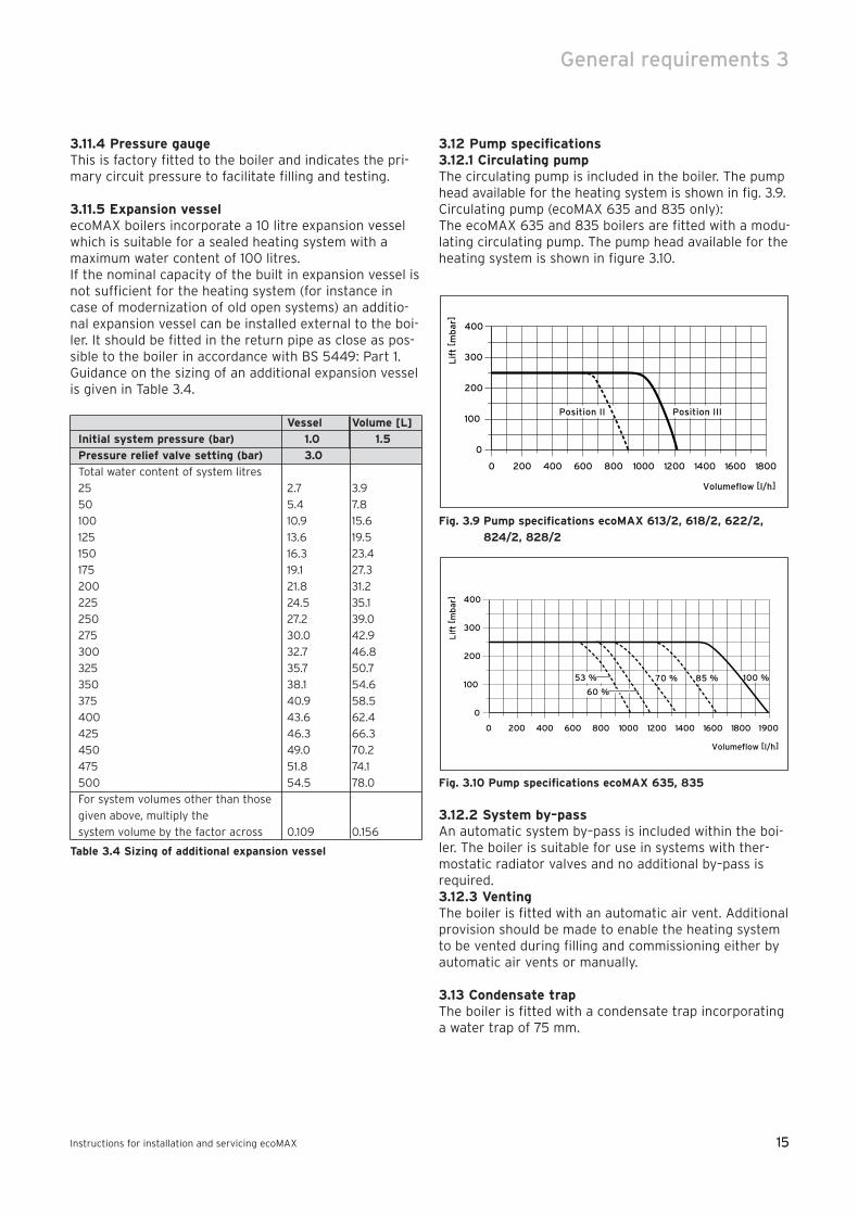
3.11.5 Expansion vesselecoMAX boilers incorporate a 10 litre expansion vesselwhich is suitable for a sealed heating system with amaximum water content of 100 litres.If the nominal capacity of the built in expansion vessel isnot sufficient for the heating system (for instance incase of modernization of old open systems) an additio-nal expansion vessel can be installed external to the boi-ler. It should be fitted in the return pipe as close as pos-sible to the boiler in accordance with BS 5449: Part 1.Guidance on the sizing of an additional expansion vesselis given in Table 3.4.
Vessel Volume [L]
Initial system pressure (bar) 1.0 1.5
Pressure relief valve setting (bar) 3.0
Total water content of system litres
25 2.7 3.9
50 5.4 7.8
100 10.9 15.6
125 13.6 19.5
150 16.3 23.4
175 19.1 27.3
200 21.8 31.2
225 24.5 35.1
250 27.2 39.0
275 30.0 42.9
300 32.7 46.8
325 35.7 50.7
350 38.1 54.6
375 40.9 58.5
400 43.6 62.4
425 46.3 66.3
450 49.0 70.2
475 51.8 74.1
500 54.5 78.0
For system volumes other than those
given above, multiply the
system volume by the factor across 0.109 0.156
Table 3.4 Sizing of additional expansion vessel
3.12 Pump specifications3.12.1 Circulating pumpThe circulating pump is included in the boiler. The pumphead available for the heating system is shown in fig. 3.9.Circulating pump (ecoMAX 635 and 835 only):The ecoMAX 635 and 835 boilers are fitted with a modu-lating circulating pump. The pump head available for theheating system is shown in figure 3.10.
Fig. 3.9 Pump specifications ecoMAX 613/2, 618/2, 622/2,
824/2, 828/2
Fig. 3.10 Pump specifications ecoMAX 635, 835
3.12.2 System by–passAn automatic system by–pass is included within the boi-ler. The boiler is suitable for use in systems with ther-mostatic radiator valves and no additional by–pass isrequired.3.12.3 VentingThe boiler is fitted with an automatic air vent. Additionalprovision should be made to enable the heating systemto be vented during filling and commissioning either byautomatic air vents or manually.
3.13 Condensate trapThe boiler is fitted with a condensate trap incorporatinga water trap of 75 mm.
400
300
200
100
0
0 200 400 600 800 1000 1200 1600
Lif
t [ m
bar
]
1800
Volumeflow [l/h]
19001400
100 %53 %
60 %
70 % 85 %
400
300
200
100
0
0 200 400 600 800 1000 1200 1600
Lif
t [ m
bar
]
Volumeflow [l/h]
18001400
Position IIIPosition II
83 41 77_12 GB04.04.qxd 22.09.2004 12:34 Uhr Seite 15

16
4 Boiler installation sequence
Instructions for installation and servicing ecoMAX16
4 Boiler installation sequence
4.1 General
Fig. 4.1
The boiler should be mounted on a flat and vertical areaof wall of sufficient area for the boiler plus the requiredclearances for installation and servicing (fig. 3.8). Theseare shown on the installation template supplied with theboiler and are:– 5 mm either side of the boiler– 145 mm below the boiler– 205 mm* above the boiler when utilising the 100 mm
outside diameter flue– 220 mm* above the boiler when utilising the 125 mm
outside diameter flue– 500 mm in front of the boiler**
Note: If the boiler is to be fitted in a timber framedbuilding, it should be fitted in accordance withBritish Gas publication DM2 ‘Guide for gasinstallations in timber framed housing’.
** This clearance is only required to enable easier access to the boiler for
servicing and may be provided by an openable door, etc.
4.1.1 Select position of boilerRefer to section ‘Boiler location’ for information regarding siting the appliance. In general the boiler mustbe positioned such that:• There is adequate space around the boiler for service
and maintenance• The boiler can be correctly flued, i.e. the flue terminal
position is sited in accordance with these instructionsand the air/flue duct can be installed in accordancewith the flue installation instructions supplied.
• All necessary pipework can be connected, includingthe pressure relief valve and condensate drain.
4.1.2 Unpack the boilerTo unpack the boiler, cut both plastic carton straps, openbox and lift out the polystyrene top packing. Lift thecardbox box upwards.
Note: Care should be taken not to scratch the whitesurface of the boiler casing.
Packed in the boiler carton are the following:• Boiler• Flow and return central heating service valves• Gas service valve• Pressure relief valve and double check valve
(ecoMAX 800)• Pre–formed copper pipework (for central heating flow
and return, gas and pressure relief valve connections)• Boiler installation template• Boiler hanging bracket • Fixing screws, wall plugs and washers• Installation and user instructions• Flue installation instructions• Guarantee card, envelope and Benchmark log book.
4.1.3 Using boiler templateFix the paper template to the wall ensure that the template is vertical. The template shows:– The position of the fixing holes for the boiler
mounting bracket (1).– The position of the connections.– The position of the flue exit hole.
Mark the position of the hanging bracket fixing holes (1).Drill 2 holes Ø 8 mm for the hanging bracket.
Note: Use alternative fixing holes where necessary.
min
min 5min 5
min 500**
min
14
5 2
05
/22
0*
83 41 77_12 GB04.04.qxd 22.09.2004 12:34 Uhr Seite 16
17
Boiler installation sequence 4
Instructions for installation and servicing ecoMAX 17
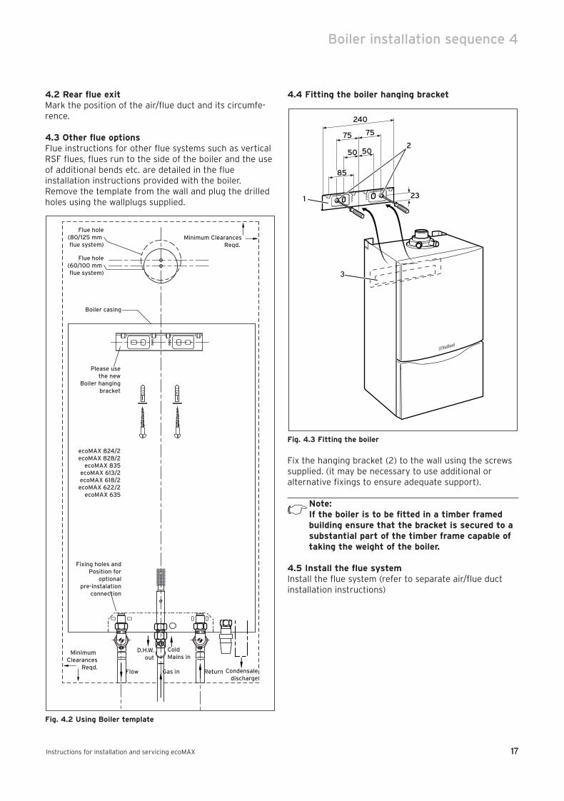
4.2 Rear flue exitMark the position of the air/flue duct and its circumfe-rence.
4.3 Other flue optionsFlue instructions for other flue systems such as verticalRSF flues, flues run to the side of the boiler and the useof additional bends etc. are detailed in the flue installation instructions provided with the boiler.Remove the template from the wall and plug the drilledholes using the wallplugs supplied.
Fig. 4.2 Using Boiler template
4.4 Fitting the boiler hanging bracket
Fig. 4.3 Fitting the boiler
Fix the hanging bracket (2) to the wall using the screwssupplied. (it may be necessary to use additional or alternative fixings to ensure adequate support).
Note:If the boiler is to be fitted in a timber framedbuilding ensure that the bracket is secured to asubstantial part of the timber frame capable oftaking the weight of the boiler.
4.5 Install the flue systemInstall the flue system (refer to separate air/flue ductinstallation instructions)
85
50
240
75 75
23
50
3
1
2
Boiler casing
Minimum Clearances
Reqd.Flow
D.H.W.out
Cold Mains in
Gas in Return Condensaledischarge
Minimum ClearancesReqd.
Flue hole(60/100 mm flue system)
Fixing holes andPosition for
optionalpre-instalation
connection
Flue hole(80/125 mm flue system)
Please usethe new
Boiler hangingbracket
ecoMAX 824/2ecoMAX 828/2
ecoMAX 835ecoMAX 613/2ecoMAX 618/2ecoMAX 622/2
ecoMAX 635
83 41 77_12 GB04.04.qxd 22.09.2004 12:34 Uhr Seite 17

18
4 Boiler installation sequence
Instructions for installation and servicing ecoMAX18
4.6 Fitting the boiler• Lift the boiler (3) up to the wall so that it is slightly
above the hanging bracket (1).
Note:Lift the boiler from either side at the bottomedge.
• Lower the boiler slowly onto the hanging bracket sothat the cross member at the rear of the boiler fullyengages onto the hanging bracket.
4.7 Removing the front case
Fig. 4.4 Removing/Refitting the case
To remove the front section of the case, proceed as follows:• Loosen the screw (1) on the bottom of the unit.• Push in the two retaining clips (2) on the bottom of
the appliance until the case is released.• Grasp the front case (3) by its bottom edge, pull it
towards the front and remove it by lifting it off theunit.
4.8 Cold water mains inlet and hot water outlet(ecoMAX 800)
Fig. 4.5 Fitting hot and cold water connections ecoMAX 800
Flush all foreign matter from the mains supply beforeconnecting to the boiler.• Connect the cold water service valve (1) to the cold
inlet water connection of the appliance with the washer provided and tighten.
• Connect a 15mm cold water inlet copper pipe (3) to thecold water service valve (1) and tighten.
• Connect a 15 mm hot water outlet pipe (4) to the outlet connection (5) of the appliance.
2
4
2
3
1
5
3
1
2
83 41 77_12 GB04.04.qxd 22.09.2004 12:34 Uhr Seite 18
19
Boiler installation sequence 4
Instructions for installation and servicing ecoMAX 19
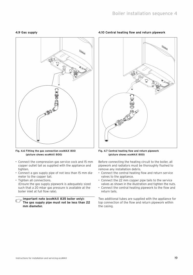
4.9 Gas supply
Fig. 4.6 Fitting the gas connection ecoMAX 800
(picture shows ecoMAX 800)
• Connect the compression gas service cock and 15 mmcopper outlet tail as supplied with the appliance andtighten.
• Connect a gas supply pipe of not less than 15 mm dia-meter to the copper tail.
• Tighten all connections.(Ensure the gas supply pipework is adequately sizedsuch that a 20 mbar gas pressure is available at theboiler inlet at full flow rate).
Important note (ecoMAX 835 boiler only): The gas supply pipe must not be less than 22mm diameter.
4.10 Central heating flow and return pipework
Fig. 4.7 Central heating flow and return pipework
(picture shows ecoMAX 800)
Before connecting the heating circuit to the boiler, allpipework and radiators must be thoroughly flushed toremove any installation debris.• Connect the central heating flow and return service
valves to the appliance.• Connect the 22 mm copper pipe tails to the service
valves as shown in the illustration and tighten the nuts.• Connect the central heating pipework to the flow and
return tails.
Two additional tubes are supplied with the appliance fortop connection of the flow and return pipework withinthe casing.
83 41 77_12 GB04.04.qxd 22.09.2004 12:34 Uhr Seite 19
20
4 Boiler installation sequence
Instructions for installation and servicing ecoMAX20
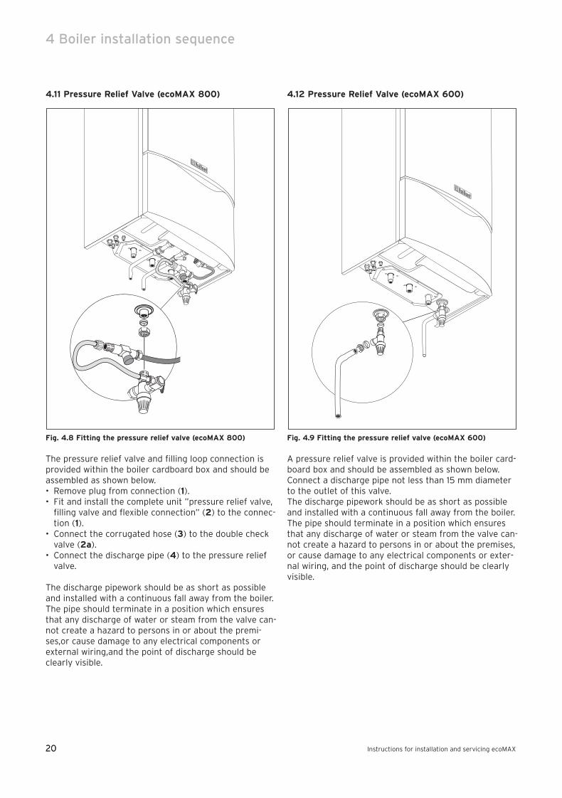
4.11 Pressure Relief Valve (ecoMAX 800)
Fig. 4.8 Fitting the pressure relief valve (ecoMAX 800)
The pressure relief valve and filling loop connection isprovided within the boiler cardboard box and should beassembled as shown below.• Remove plug from connection (1).• Fit and install the complete unit ”pressure relief valve,
filling valve and flexible connection” (2) to the connec-tion (1).
• Connect the corrugated hose (3) to the double checkvalve (2a).
• Connect the discharge pipe (4) to the pressure reliefvalve.
The discharge pipework should be as short as possibleand installed with a continuous fall away from the boiler.The pipe should terminate in a position which ensuresthat any discharge of water or steam from the valve can-not create a hazard to persons in or about the premi-ses,or cause damage to any electrical components orexternal wiring,and the point of discharge should beclearly visible.
4.12 Pressure Relief Valve (ecoMAX 600)
Fig. 4.9 Fitting the pressure relief valve (ecoMAX 600)
A pressure relief valve is provided within the boiler card-board box and should be assembled as shown below.Connect a discharge pipe not less than 15 mm diameterto the outlet of this valve.The discharge pipework should be as short as possibleand installed with a continuous fall away from the boiler.The pipe should terminate in a position which ensuresthat any discharge of water or steam from the valve can-not create a hazard to persons in or about the premises,or cause damage to any electrical components or exter-nal wiring, and the point of discharge should be clearlyvisible.
83 41 77_12 GB04.04.qxd 22.09.2004 12:34 Uhr Seite 20
21
Boiler installation sequence 4
Instructions for installation and servicing ecoMAX 21
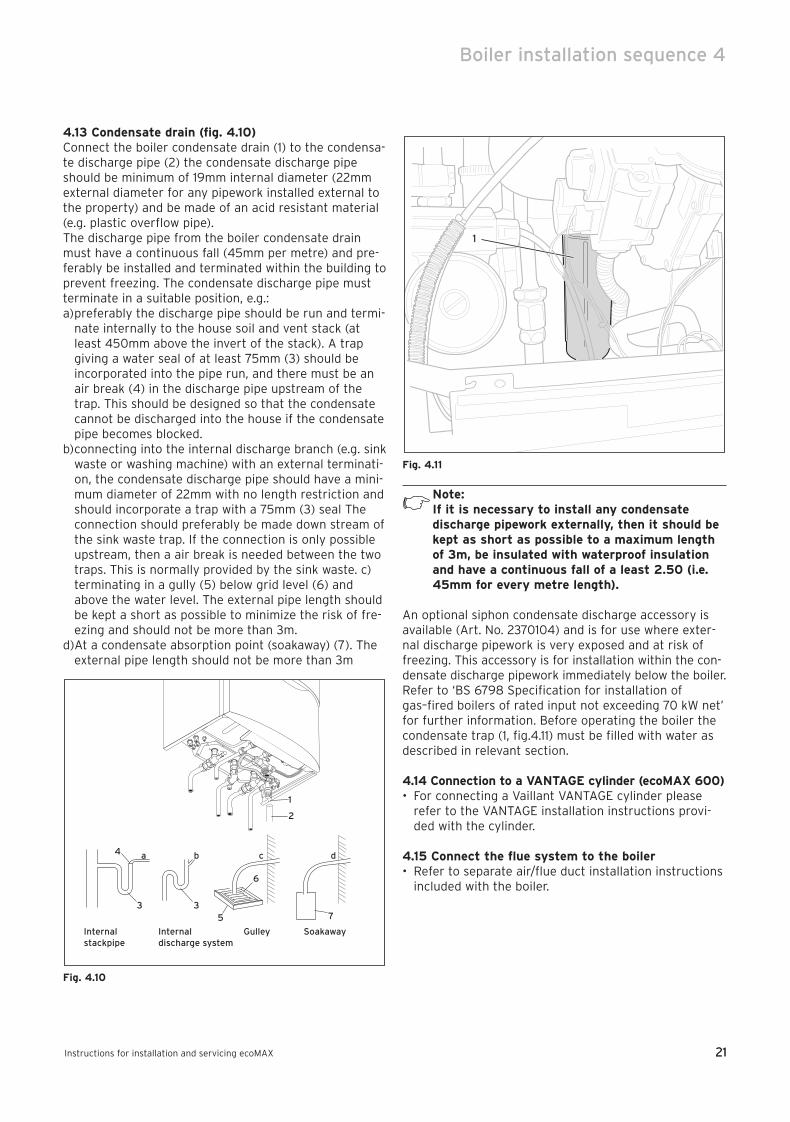
4.13 Condensate drain (fig. 4.10)Connect the boiler condensate drain (1) to the condensa-te discharge pipe (2) the condensate discharge pipeshould be minimum of 19mm internal diameter (22mmexternal diameter for any pipework installed external tothe property) and be made of an acid resistant material(e.g. plastic overflow pipe).The discharge pipe from the boiler condensate drainmust have a continuous fall (45mm per metre) and pre-ferably be installed and terminated within the building toprevent freezing. The condensate discharge pipe mustterminate in a suitable position, e.g.:a)preferably the discharge pipe should be run and termi-
nate internally to the house soil and vent stack (atleast 450mm above the invert of the stack). A trapgiving a water seal of at least 75mm (3) should beincorporated into the pipe run, and there must be anair break (4) in the discharge pipe upstream of thetrap. This should be designed so that the condensatecannot be discharged into the house if the condensatepipe becomes blocked.
b)connecting into the internal discharge branch (e.g. sinkwaste or washing machine) with an external terminati-on, the condensate discharge pipe should have a mini-mum diameter of 22mm with no length restriction andshould incorporate a trap with a 75mm (3) seal Theconnection should preferably be made down stream ofthe sink waste trap. If the connection is only possibleupstream, then a air break is needed between the twotraps. This is normally provided by the sink waste. c)terminating in a gully (5) below grid level (6) andabove the water level. The external pipe length shouldbe kept a short as possible to minimize the risk of fre-ezing and should not be more than 3m.
d)At a condensate absorption point (soakaway) (7). Theexternal pipe length should not be more than 3m
Fig. 4.10
Fig. 4.11
Note:If it is necessary to install any condensatedischarge pipework externally, then it should bekept as short as possible to a maximum lengthof 3m, be insulated with waterproof insulationand have a continuous fall of a least 2.50 (i.e.45mm for every metre length).
An optional siphon condensate discharge accessory isavailable (Art. No. 2370104) and is for use where exter-nal discharge pipework is very exposed and at risk offreezing. This accessory is for installation within the con-densate discharge pipework immediately below the boiler. Refer to ‘BS 6798 Specification for installation ofgas–fired boilers of rated input not exceeding 70 kW net’for further information. Before operating the boiler thecondensate trap (1, fig.4.11) must be filled with water asdescribed in relevant section.
4.14 Connection to a VANTAGE cylinder (ecoMAX 600)• For connecting a Vaillant VANTAGE cylinder please
refer to the VANTAGE installation instructions provi-ded with the cylinder.
4.15 Connect the flue system to the boiler• Refer to separate air/flue duct installation instructions
included with the boiler.
1
Internal stackpipe
Internal discharge system
Gulley Soakaway
a b c d
1
2
35
6
37
4
83 41 77_12 GB04.04.qxd 22.09.2004 12:34 Uhr Seite 21
22
4 Boiler installation sequence
Instructions for installation and servicing ecoMAX22
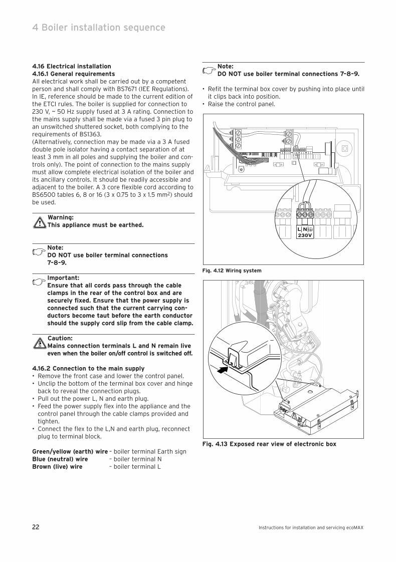
4.16 Electrical installation4.16.1 General requirementsAll electrical work shall be carried out by a competentperson and shall comply with BS7671 (IEE Regulations).In IE, reference should be made to the current edition ofthe ETCI rules. The boiler is supplied for connection to230 V, ~ 50 Hz supply fused at 3 A rating. Connection tothe mains supply shall be made via a fused 3 pin plug toan unswitched shuttered socket, both complying to therequirements of BS1363.(Alternatively, connection may be made via a 3 A fuseddouble pole isolator having a contact separation of atleast 3 mm in all poles and supplying the boiler and con-trols only). The point of connection to the mains supplymust allow complete electrical isolation of the boiler andits ancillary controls. It should be readily accessible andadjacent to the boiler. A 3 core flexible cord according toBS6500 tables 6, 8 or 16 (3 x 0.75 to 3 x 1.5 mm2) shouldbe used.
Warning:This appliance must be earthed.
Note:DO NOT use boiler terminal connections 7–8–9.
Important:Ensure that all cords pass through the cableclamps in the rear of the control box and aresecurely fixed. Ensure that the power supply isconnected such that the current carrying con-ductors become taut before the earth conductorshould the supply cord slip from the cable clamp.
Caution:Mains connection terminals L and N remain liveeven when the boiler on/off control is switched off.
4.16.2 Connection to the main supply• Remove the front case and lower the control panel.• Unclip the bottom of the terminal box cover and hinge
back to reveal the connection plugs.• Pull out the power L, N and earth plug.• Feed the power supply flex into the appliance and the
control panel through the cable clamps provided andtighten.
• Connect the flex to the L,N and earth plug, reconnectplug to terminal block.
Green/yellow (earth) wire – boiler terminal Earth signBlue (neutral) wire – boiler terminal NBrown (live) wire – boiler terminal L
Note: DO NOT use boiler terminal connections 7–8–9.
• Refit the terminal box cover by pushing into place untilit clips back into position.
• Raise the control panel.
Fig. 4.12 Wiring system
Fig. 4.13 Exposed rear view of electronic box
83 41 77_12 GB04.04.qxd 22.09.2004 12:34 Uhr Seite 22

23
Boiler installation sequence 4
Instructions for installation and servicing ecoMAX 23
4.16.3 Electronic board layout4.16.3 Electronic board layou
Fig. 4.14: Connection wiring ecoMAX 613/2, 618/2, 622/2, 824/2, 828/2
98
75
43
NL
NL
Pu
mp
C
on
tactth
erm
24
V I
23
0V
RT
24
V2
30
VR
T 2
30
V
X 4
X 7
X 2
13 1
Co
din
g resista
nce
11
1
X 6 Diagnostic connection
Diverter valve
Connection for multi–function module 306 253
Room thermostat 24 V: Connections 7, 8 and 9Caution: DO NOT connect directly to mainssupply: danger of irreparable damage toelectronic system
Room thermostat 230 V/50 Hz(remove bridge for connection)
Heating pump connection
Mains power supply: 230 V/50 Hz
Under–floor heating overload thermostat, 20 V(remove bridge for connection)
Edge connector for Vaillant weathercompensator
83 41 77_12 GB04.04.qxd 22.09.2004 12:34 Uhr Seite 23
24
4 Boiler installation sequence
Instructions for installation and servicing ecoMAX24
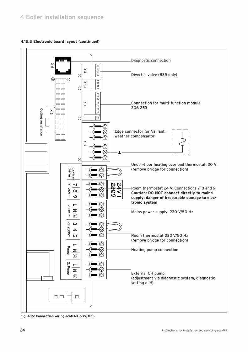
4.16.3 Electronic board layout (continued)
Fig. 4.15: Connection wiring ecoMAX 635, 835
98
75
43
NL
NL
Pu
mp
2. P
um
pC
on
tactth
erm
L N
24
V I
23
0V
RT
24
V2
30
VR
T 2
30
V
X 4
X 10
X 7
X 8
X 2
13X
6
11
11
1
Co
din
g resistan
ce
Diagnostic connection
Diverter valve (835 only)
Connection for multi–function module 306 253
Room thermostat 24 V: Connections 7, 8 and 9Caution: DO NOT connect directly to mainssupply: danger of irreparable damage to elec-tronic system
Room thermostat 230 V/50 Hz(remove bridge for connection)
Heating pump connection
Mains power supply: 230 V/50 Hz
Under–floor heating overload thermostat, 20 V(remove bridge for connection)
Edge connector for Vaillantweather compensator
External CH pump(adjustment via diagnostic system, diagnosticsetting d.16)
83 41 77_12 GB04.04.qxd 22.09.2004 12:34 Uhr Seite 24
25
Boiler installation sequence 4
Instructions for installation and servicing ecoMAX 25
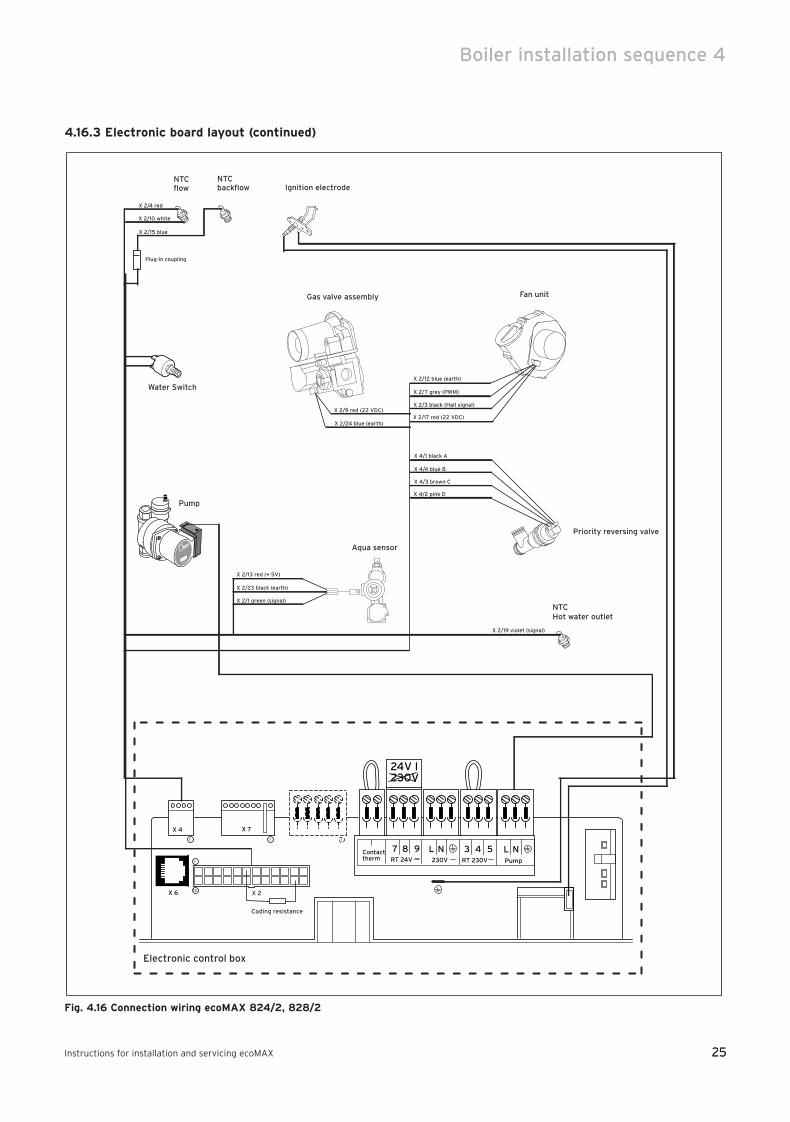
4.16.3 Electronic board layout (continued)
Fig. 4.16 Connection wiring ecoMAX 824/2, 828/2
Electronic control box
Aqua sensor
NTC Hot water outlet
Fan unit
Ignition electrodeNTCflow
Priority reversing valve
Gas valve assembly
NTCbackflow
X 2/4 red
X 2/10 white
X 2/15 blue
Plug-in coupling
Pump
X 2/9 red (22 VDC)
X 2/24 blue (earth)
X 2/12 blue (earth)
X 2/7 grey (PWM)
X 2/3 black (Hall signal)
X 2/17 red (22 VDC)
X 4/3 brown C
X 4/2 pink D
X 4/1 black A
X 4/4 blue B
X 2/13 red (+ 5V)
X 2/23 black (earth)
X 2/1 green (signal)
987 543 NLNLPump
Contacttherm
24V I230V
RT 24V 230V RT 230V
X 4 X 7
X 213
1
Coding resistance
1 1 1
X 6
X 2/19 violet (signal)
Water Switch
83 41 77_12 GB04.04.qxd 22.09.2004 12:34 Uhr Seite 25
26
4 Boiler installation sequence
Instructions for installation and servicing ecoMAX26
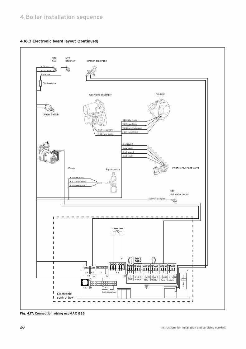
4.16.3 Electronic board layout (continued)
Fig. 4.17: Connection wiring ecoMAX 835
Aqua sensor
NTC Hot water outlet
Fan unit
Ignition electrode
Pump
NTCflow
Priority reversing valve
Gas valve assembly
NTCbackflow
X 2/4 red
X 2/10 white
X 2/15 blue
Plug-in coupling
Electroniccontrol box
987 543 NLNLPump 2. Pump
Contacttherm
L N
24V I230V
RT 24V 230V RT 230V
X 4 X 10 X 7 X 8
X 6 X 2
Coding resistance
13
11 1 1
1
X 2/9 red (22 VDC)
X 2/24 blue (earth)
X 2/12 blue (earth)
X 2/7 grey (PWM)
X 2/3 black (Hall signal)
X 2/17 red (22 VDC)
X 4/3 brown C
X 4/2 pink D
X 4/1 black A
X 4/4 blue B
X 2/13 red (+ 5V)
X 2/23 black (earth)
X 2/1 green (signal)
X 2/19 violet (signal)
Water Switch
83 41 77_12 GB04.04.qxd 22.09.2004 12:34 Uhr Seite 26
27
Boiler installation sequence 4
Instructions for installation and servicing ecoMAX 27
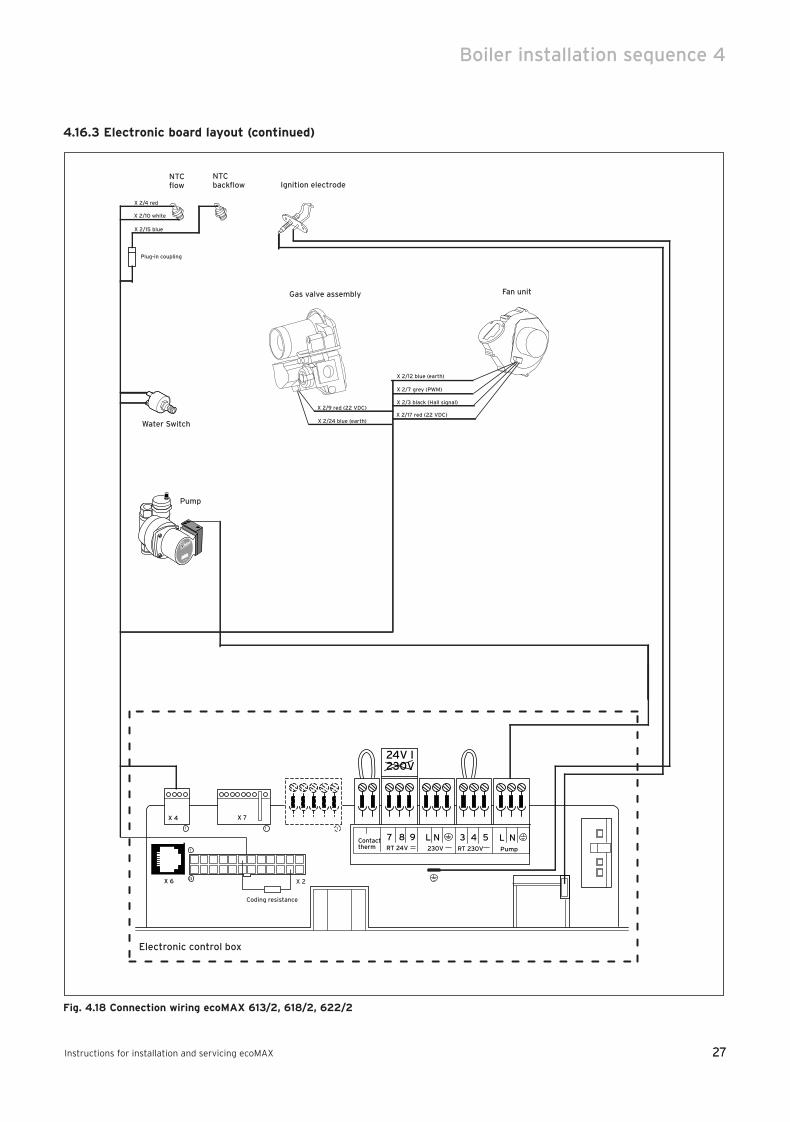
4.16.3 Electronic board layout (continued)
Fig. 4.18 Connection wiring ecoMAX 613/2, 618/2, 622/2
Fan unit
Ignition electrodeNTCflow
Gas valve assembly
NTCbackflow
X 2/4 red
X 2/10 white
X 2/15 blue
Plug-in coupling
Electronic control box
987 543 NLNLPump
Contacttherm
24V I230V
RT 24V 230V RT 230V
X 4 X 7
X 213
1
Coding resistance
1 1 1
X 6
Pump
Water Switch
X 2/9 red (22 VDC)
X 2/24 blue (earth)
X 2/12 blue (earth)
X 2/7 grey (PWM)
X 2/3 black (Hall signal)
X 2/17 red (22 VDC)
83 41 77_12 GB04.04.qxd 22.09.2004 12:34 Uhr Seite 27
28
4 Boiler installation sequence
Instructions for installation and servicing ecoMAX28
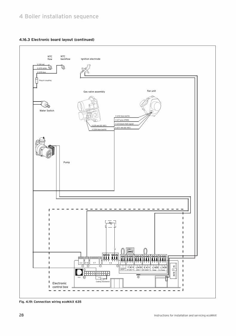
4.16.3 Electronic board layout (continued)
Fig. 4.19: Connection wiring ecoMAX 635
Fan unit
Ignition electrode
Pump
NTCflow
Gas valve assembly
NTCbackflow
X 2/4 red
X 2/10 white
X 2/15 blue
Plug-in coupling
Electroniccontrol box
987 543 NLNLPump 2. Pump
Contacttherm
L N
24V I230V
RT 24V 230V RT 230V
X 4 X 10 X 7 X 8
X 6 X 2
Coding resistance
13
11 1 1
1
X 2/9 red (22 VDC)
X 2/24 blue (earth)
X 2/12 blue (earth)
X 2/7 grey (PWM)
X 2/3 black (Hall signal)
X 2/17 red (22 VDC)
Water Switch
83 41 77_12 GB04.04.qxd 22.09.2004 12:34 Uhr Seite 28
29
Boiler installation sequence 4
Instructions for installation and servicing ecoMAX 29
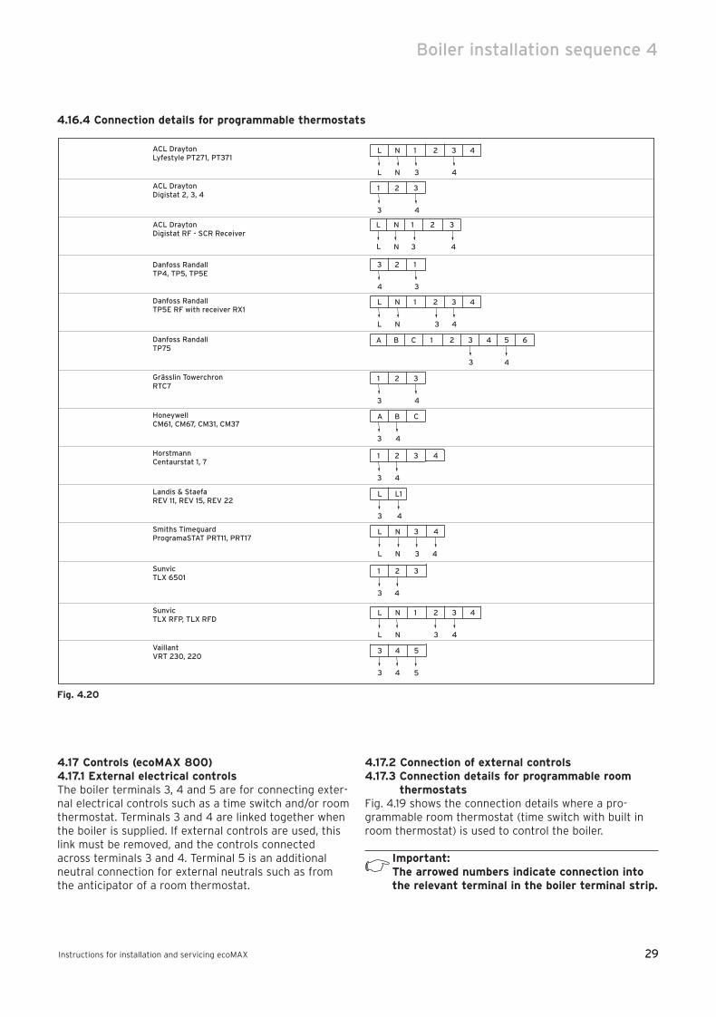
4.16.4 Connection details for programmable thermostats
Fig. 4.20
L N 2 3 4
L N 3 4
1ACL DraytonLyfestyle PT271, PT371
ACL DraytonDigistat 2, 3, 4
ACL DraytonDigistat RF - SCR Receiver
Danfoss RandallTP4, TP5, TP5E
Danfoss RandallTP5E RF with receiver RX1
Danfoss RandallTP75
Grässlin TowerchronRTC7
HoneywellCM61, CM67, CM31, CM37
HorstmannCentaurstat 1, 7
Landis & StaefaREV 11, REV 15, REV 22
1 2
3 4
3
SunvicTLX 6501
SunvicTLX RFP, TLX RFD
VaillantVRT 230, 220
N 1 3
N 3
2L
L 4
3 2
4 3
1
L N 2 3 4
L N 3 4
1
B C 2 3 41A
3
5 6
4
1 2
3 4
3
A B
3 4
C
1 2 4
3 4
3
L L1
3 4
Smiths TimeguardProgramaSTAT PRT11, PRT17
L N 4
L N
3
3 4
1 2
3 4
3
L N 2 3 4
L N 3 4
1
3 4
3 4
5
5
4.17 Controls (ecoMAX 800) 4.17.1 External electrical controlsThe boiler terminals 3, 4 and 5 are for connecting exter-nal electrical controls such as a time switch and/or roomthermostat. Terminals 3 and 4 are linked together whenthe boiler is supplied. If external controls are used, thislink must be removed, and the controls connectedacross terminals 3 and 4. Terminal 5 is an additionalneutral connection for external neutrals such as fromthe anticipator of a room thermostat.
4.17.2 Connection of external controls4.17.3 Connection details for programmable room
thermostatsFig. 4.19 shows the connection details where a pro-grammable room thermostat (time switch with built inroom thermostat) is used to control the boiler.
Important:The arrowed numbers indicate connection intothe relevant terminal in the boiler terminal strip.
83 41 77_12 GB04.04.qxd 22.09.2004 12:34 Uhr Seite 29

Fig. 4.22
3987
MAINS
SUPPLY
230 V 50 Hz
L
L
L N
N
NN
20 VDC (DO NOT USE 7, 8, 9 IN UK!)
3 A FUSE SWITCH CONTACTS
ROOM THERMOSTAT
CLOCK
4 5
30
4 Boiler installation sequence
Instructions for installation and servicing ecoMAX30
4.17.4 Connection details for time switch
Fig. 4.21
L N 2 3 4
L N 3 4
1ACL DraytonTempus 1, Tempus 2Lyfestyle LP111, LP711
ACL DraytonSwitchmasterSM300
ACL DraytonSwitchmaster 980
Danfoss Randall103 Series
Danfoss RandallSet 1E, TS975
Danfoss RandallTS715
Grässlin TowerchronQE1, QM1
HoneywellST610A, ST6100C
HorstmannChannel PlusH11, H17, 425 Coronet
HorstmannCentaur PlusC11, C17
L N 2 3 4
L N 4 3
1
Potterton MysonEP 4002, EP 5002
Smiths TimeguardSupplyMASTERFST11, FST17
SunvicSelect 107
N 1 A B C
N 4
2L
L 3
3 4
1 2 6 5 E
4 L3 N
3
E
N E 2 3 4
N E
1L
L 3
5 6
4
L N 2 3 4
L N 3 4
1
L N 2 3 4
L N 3 4
1
L N 2 3 4
L N 3 4
1
N E 2 3 4
N E
1L
L 3
5 6
4
N E 2 3 4
N E
1L
L 3 4
L N 2 3 4
L N 3 4
1
L N 2 3 4
L N 3 4
1
A B D L N
L N
CN
E3
1 2
4
3 4 5 E
1 2 4
4 3 2/L 1/N
3 6 5 mains supply
L N E
E
Landis & StaefaRWB7, RWB30
83 41 77_12 GB04.04.qxd 22.09.2004 12:34 Uhr Seite 30
31Instructions for installation and servicing ecoMAX 31
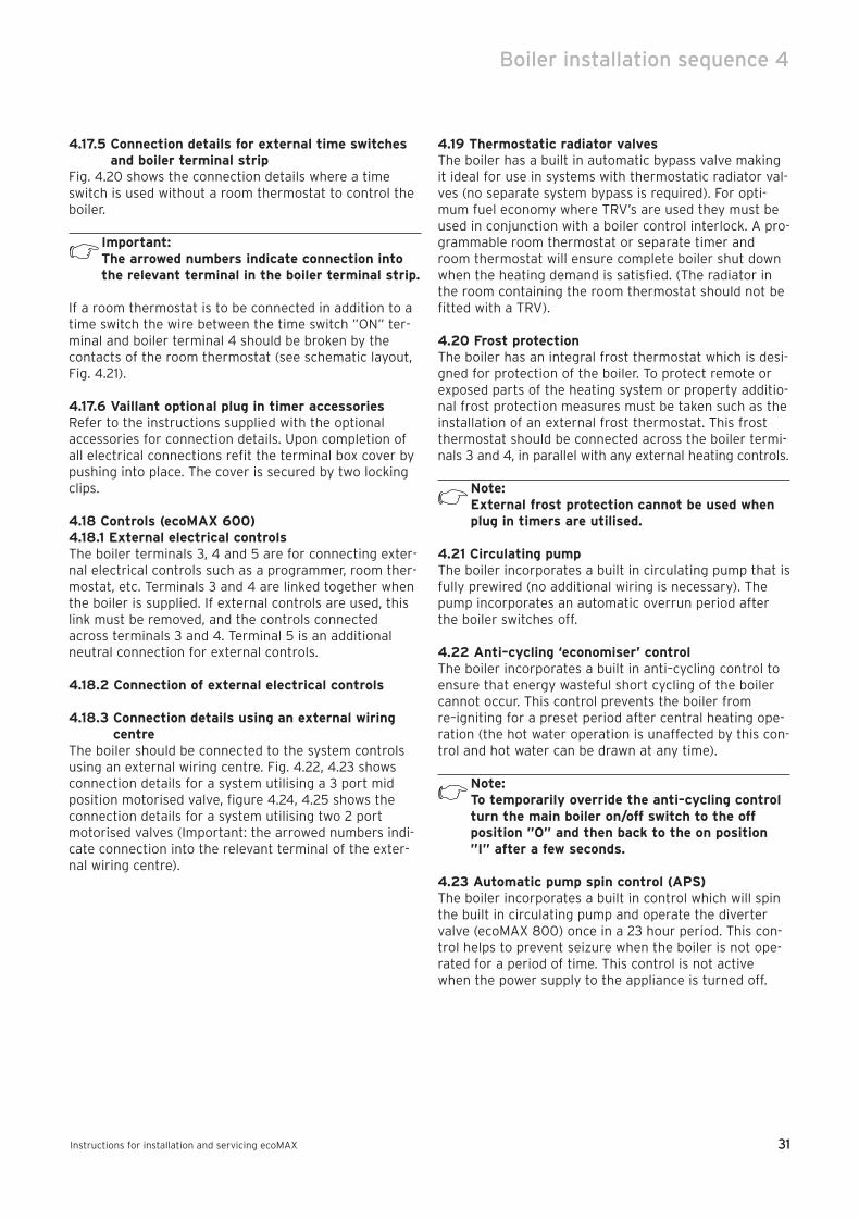
4.17.5 Connection details for external time switchesand boiler terminal strip
Fig. 4.20 shows the connection details where a timeswitch is used without a room thermostat to control theboiler.
Important:The arrowed numbers indicate connection intothe relevant terminal in the boiler terminal strip.
If a room thermostat is to be connected in addition to atime switch the wire between the time switch ”ON” ter-minal and boiler terminal 4 should be broken by thecontacts of the room thermostat (see schematic layout,Fig. 4.21).
4.17.6 Vaillant optional plug in timer accessoriesRefer to the instructions supplied with the optionalaccessories for connection details. Upon completion ofall electrical connections refit the terminal box cover bypushing into place. The cover is secured by two lockingclips.
4.18 Controls (ecoMAX 600)4.18.1 External electrical controlsThe boiler terminals 3, 4 and 5 are for connecting exter-nal electrical controls such as a programmer, room ther-mostat, etc. Terminals 3 and 4 are linked together whenthe boiler is supplied. If external controls are used, thislink must be removed, and the controls connectedacross terminals 3 and 4. Terminal 5 is an additionalneutral connection for external controls.
4.18.2 Connection of external electrical controls
4.18.3 Connection details using an external wiringcentre
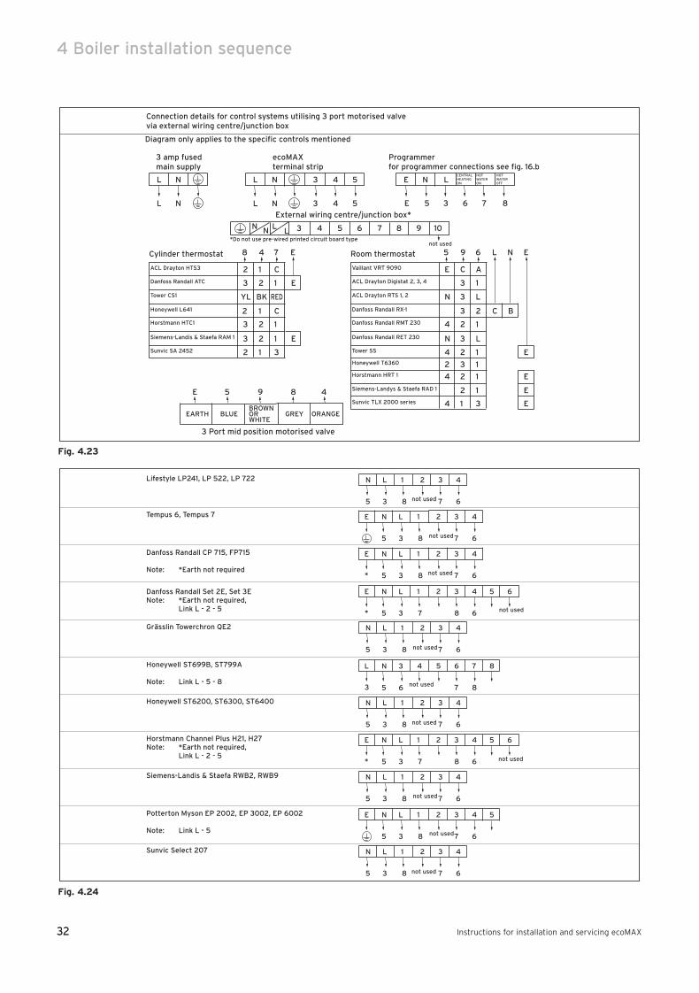
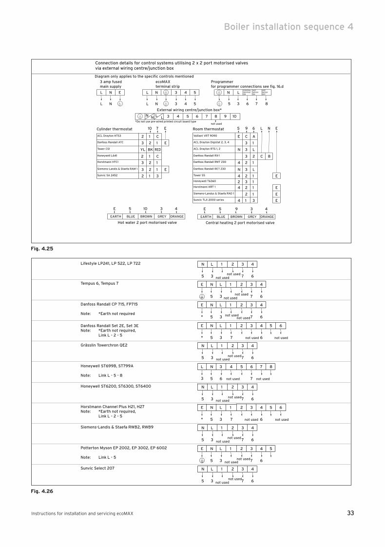
The boiler should be connected to the system controlsusing an external wiring centre. Fig. 4.22, 4.23 showsconnection details for a system utilising a 3 port midposition motorised valve, figure 4.24, 4.25 shows theconnection details for a system utilising two 2 portmotorised valves (Important: the arrowed numbers indi-cate connection into the relevant terminal of the exter-nal wiring centre).
4.19 Thermostatic radiator valvesThe boiler has a built in automatic bypass valve makingit ideal for use in systems with thermostatic radiator val-ves (no separate system bypass is required). For opti-mum fuel economy where TRV’s are used they must beused in conjunction with a boiler control interlock. A pro-grammable room thermostat or separate timer androom thermostat will ensure complete boiler shut downwhen the heating demand is satisfied. (The radiator inthe room containing the room thermostat should not befitted with a TRV).
4.20 Frost protectionThe boiler has an integral frost thermostat which is desi-gned for protection of the boiler. To protect remote orexposed parts of the heating system or property additio-nal frost protection measures must be taken such as theinstallation of an external frost thermostat. This frostthermostat should be connected across the boiler termi-nals 3 and 4, in parallel with any external heating controls.
Note:External frost protection cannot be used whenplug in timers are utilised.
4.21 Circulating pumpThe boiler incorporates a built in circulating pump that isfully prewired (no additional wiring is necessary). Thepump incorporates an automatic overrun period afterthe boiler switches off.
4.22 Anti–cycling ‘economiser’ controlThe boiler incorporates a built in anti–cycling control toensure that energy wasteful short cycling of the boilercannot occur. This control prevents the boiler fromre–igniting for a preset period after central heating ope-ration (the hot water operation is unaffected by this con-trol and hot water can be drawn at any time).
Note:To temporarily override the anti–cycling controlturn the main boiler on/off switch to the offposition ”0” and then back to the on position”I” after a few seconds.
4.23 Automatic pump spin control (APS)The boiler incorporates a built in control which will spinthe built in circulating pump and operate the divertervalve (ecoMAX 800) once in a 23 hour period. This con-trol helps to prevent seizure when the boiler is not ope-rated for a period of time. This control is not activewhen the power supply to the appliance is turned off.
Boiler installation sequence 4
83 41 77_12 GB04.04.qxd 22.09.2004 12:34 Uhr Seite 31
32
4 Boiler installation sequence
Instructions for installation and servicing ecoMAX32
Fig. 4.23
Fig. 4.24
N L 2 3 4
5 3 8 7 6
1
not used
Lifestyle LP241, LP 522, LP 722
Tempus 6, Tempus 7
Danfoss Randall CP 715, FP715
Note: *Earth not required
Danfoss Randall Set 2E, Set 3ENote: *Earth not required,
Link L - 2 - 5
Grässlin Towerchron QE2
Honeywell ST699B, ST799A
Note: Link L - 5 - 8
Honeywell ST6200, ST6300, ST6400
Horstmann Channel Plus H21, H27Note: *Earth not required,
Link L - 2 - 5
Siemens-Landis & Staefa RWB2, RWB9
Potterton Myson EP 2002, EP 3002, EP 6002
Note: Link L - 5
Sunvic Select 207
N L 2 3 4
5 3 8 7 6
1E
N L 2 3 4
5 3 8 7 6
1E
*
N L 2 3 4
5 3 7 8 6
1E
*
5 6
N L 2 3 4
5 3 8 7 6
1
N 3 5 6 7
5 6 7 8
4L
3
8
N L 2 3 4
5 3 8 7 6
1
N L 2 3 4
5 3 7 8 6
1E
*
5 6
N L 2 3 4
5 3 8 7 6
1
N L 2 3 4
5 3 8 7 6
1
N L 2 3 4
5 3 8 7 6
1E 5
not used
not used
not used
not used
not used
not used
not used
not used
not used
not used
Connection details for control systems utilising 3 port motorised valve via external wiring centre/junction box
Diagram only applies to the specific controls mentioned
L N L N 3 4 5 E N LCENTRALHEATINGON
HOTWATERON
HOTWATEROFF
3 amp fusedmain supply
ecoMAXterminal strip
Programmerfor programmer connections see fig. 16.b
L N L N 3 4 5 E 5 3 6 7 8
External wiring centre/junction box*
3 4 5 6 7 8 9 10N N LL
*Do not use pre-wired printed circuit board typenot used
EARTH BLUEBROWNORWHITE
GREY ORANGE
3 Port mid position motorised valve
4E 5 89
E C A
N
4
N
4
2
4
4
3
3
3
3
3
2
2
2
2
1
1
L
2
1
L
1
1
1
1
3
C B
E
E
E
E
Vaillant VRT 9090
ACL Drayton Digistat 2, 3, 4
ACL Drayton RTS 1, 2
Danfoss Randall RX-1
Danfoss Randall RMT 230
Danfoss Randall RET 230
Tower SS
Honeywell T6360
Horstmann HRT 1
Siemens-Landys & Staefa RAD 1
Sunvic TLX 2000 series
5 9 6 L N ERoom thermostat
2 1 C
YL
3
3
2
2
BK
1
2
2
1
1
RED
C
1
1
3
ACL Drayton HTS3
Danfoss Randall ATC
Tower CS1
Honeywell L641
Horstmann HTC1
Siemens-Landis & Staefa RAM 1
Sunvic SA 2452
8 4 7 ECylinder thermostat
3 E
2
E
83 41 77_12 GB04.04.qxd 22.09.2004 12:34 Uhr Seite 32
33
Boiler installation sequence 4
Instructions for installation and servicing ecoMAX 33
Fig. 4.25
Fig. 4.26
N L 2 3 4
5 3 not used 7 6
1
not used
Lifestyle LP241, LP 522, LP 722
Tempus 6, Tempus 7
Danfoss Randall CP 715, FP715
Note: *Earth not required
Danfoss Randall Set 2E, Set 3ENote: *Earth not required,
Link L - 2 - 5
Grässlin Towerchron QE2
Honeywell ST699B, ST799A
Note: Link L - 5 - 8
Honeywell ST6200, ST6300, ST6400
Horstmann Channel Plus H21, H27Note: *Earth not required,
Link L - 2 - 5
Siemens-Landis & Staefa RWB2, RWB9
Potterton Myson EP 2002, EP 3002, EP 6002
Note: Link L - 5
Sunvic Select 207
N L 2 3 4
5 3 not used 7 6
1
not used
N L 2 3 4
5 3 not used 7 6
1E 5
not used
N L 2 3 4
5 3 7 6
1E
not usednot used
N L 2 3 4
5 3 7 6
1
not used
E
* not used
N L 2 3 4
5 3 7 6
1E
* not used
5 6
not used
N L 2 3 4
5 3 7 6
1
not usednot used
N 3 5 6 7
5 6 not used 7
4L
3
8
not used
N L 2 3 4
5 3 7 6
1
not usednot used
N L 2 3 4
5 3 7 6
1E
* not used
5 6
not used
N L 2 3 4
5 3 7 6
1
not usednot used
Connection details for control systems utilising 2 x 2 port motorised valves via external wiring centre/junction box
Diagram only applies to the specific controls mentioned
L N L N 3 4 5 N LCENTRALHEATINGON
HOTWATERON
HOTWATEROFF
3 amp fusedmain supply
ecoMAXterminal strip
Programmerfor programmer connections see fig. 16.d
L N L N 3 4 5 5 3 6 7 8
External wiring centre/junction box*
3 4 5 6 7 8 9 10N N LL
*Do not use pre-wired printed circuit board typenot used
EARTH BLUE BROWN GREY ORANGE
Hot water 2 port motorised valve
4E 5 310
E C A
N
4
N
4
2
4
4
3
3
3
3
3
2
2
2
2
1
1
L
2
1
L
1
1
1
1
3
C B
E
E
E
E
Vaillant VRT 9090
ACL Drayton Digistat 2, 3, 4
ACL Drayton RTS 1, 2
Danfoss Randall RX-1
Danfoss Randall RMT 230
Danfoss Randall RET 230
Tower SS
Honeywell T6360
Horstmann HRT 1
Siemens-Landys & Staefa RAD 1
Sunvic TLX 2000 series
5 9 6 L N ERoom thermostat
2 1 C
YL
3
3
2
2
BK
1
2
2
1
1
RED
C
1
1
3
ACL Drayton HTS3
Danfoss Randall ATC
Tower CS1
Honeywell L641
Horstmann HTC1
Siemens-Landis & Staefa RAM 1
Sunvic SA 2452
10 7 ECylinder thermostat
3 E
2
E
E
EARTH BLUE BROWN GREY ORANGE
Central heating 2 port motorised valve
4E 5 39
83 41 77_12 GB04.04.qxd 22.09.2004 12:34 Uhr Seite 33
34
5 Commissioning Part I
Instructions for installation and servicing ecoMAX34
5 Commissioning Part I
5.1 Preliminary electrical checksCheck the electrical installation by carrying out shortcircuit, earth continuity and resistance to earth tests anda check for correct polarity.
5.2 Gas supplyThe complete gas installation including the gas metermust be inspected, tested for soundness and purged inaccordance with BS 6891. In IE the current edition of IS 813. The gas supply to the boiler can be purged byslackening the gas service valve beneath the boiler.Ensure that there is adequate ventilation, extinguish allnaked flames and do not smoke whilst purging. Afterpurging, the gas service valve connection must beretightened and tested for soundness. (The boiler itselfdoes not require purging as this will be done by theautomatic burner sequence control).
5.3 Cold water supply (ecoMAX 800)Open all domestic hot water taps supplied by the boiler,turn on the mains water supply to the boiler and openthe mains water isolating valve below the boiler. Waterwill now flow through the boiler to the hot taps. Startingwith the lowest tap supplied, turn the hot taps off one ata time until the hot water pipework is purged of air.Check all hot and cold water pipework for leaks. Insertdrawing showing 2 filling valve positions
5.4 Filling the heating system (ecoMAX 800)Proceed as follows to fill the system:• Open all radiator valves on the system.• Ensure that the boiler CH service valves are open.• Check the flexible filling loop is connected.• Locate the filling valve handle (1) and open. • Locate the filling valve handle (2) and open to allow
water to enter the system. Starting with the lowestradiator, open the radiator air release until water (clearof bubbles) is emitted.
• Repeat this at all radiators until the complete systemis full, all air locks have been cleared and the boilerpressure gauge reads 1.5 bar. Release any air from thepump by slackening the centre screw. Turn off the fil-ling valve (2) and fully close filling valve (1).
• The boiler is equipped with an automatic air releasevalve. To allow this to vent the boiler, the cap on thetop must be slackened by 1 –2 turns (This cap must beleft slackened during boiler operation to ensure anyresidual air or system gases are released).
• Check the heating system and boiler connections aresound.
5.5 Initial system flush (”Cold”)The whole of the heating system must be flushed out atleast twice: once cold, and once hot as instructed lateron page 68. Open all radiator or heating valves and theboiler CH service valves and drain the heating systemand boiler completely from the lowest points of the
system via 1/2” BSP drain taps (opened full bore to remo-ve any installation debris prior to lighting the boiler).Refill the heating system. Check the operation of thepressure relief valve by rotating the knob on the valve.Now check the water pressure in the unit again (and addmore water if necessary). Close both filling valves anddisconnect the temporary connection.
5.6 Filling the heating system (ecoMAX 600)The boiler and the heating system should be filled usinga filling method as described on page 15.• Ensure that the boiler CH service valves are open.• Partially open the filling valve and allow water to enter
the system. Starting with the lowest radiator, open theradiator air release until water (clear of bubbles) isemitted.
• Repeat this at all radiators until the complete systemis full, all air locks have been cleared and the boilerpressure gauge reads 1.5 bar. Release any air from thepump by slackening the centre screw.
• The boiler is equipped with an automatic air releasevalve. To allow this to vent the boiler, the cap on thetop must be slackened by 1 – 2 turns. (This cap mustbe left slackened during boiler operation to ensure anyresidual air or system gases are released).
• Check the heating system and boiler connections aresound.
5.7 Initial system flush (”Cold”)The whole of the heating system must be flushed out atleast twice: once cold, and once hot as instructed lateron page 40.• Open all radiator or heating valves and the boiler CH
service valves and drain the heating system and boilercompletely from the lowest points of the system via1/2” BSP drain taps (opened full bore to remove anyinstallation debris prior to lighting the boiler).
• Refill the heating system.• Check the operation of the pressure relief valve by
rotating the knob on the valve.
5.8 Filling condensate trapRemove the lower part of the condensate trap (1, fig. 5.1) by unscrewing and fill with water to about 10 mm from the top. Refit to boiler.
Fig. 5.1 Filling the heating system (ecoMAX 800)
2
1
83 41 77_12 GB04.04.qxd 22.09.2004 12:34 Uhr Seite 34
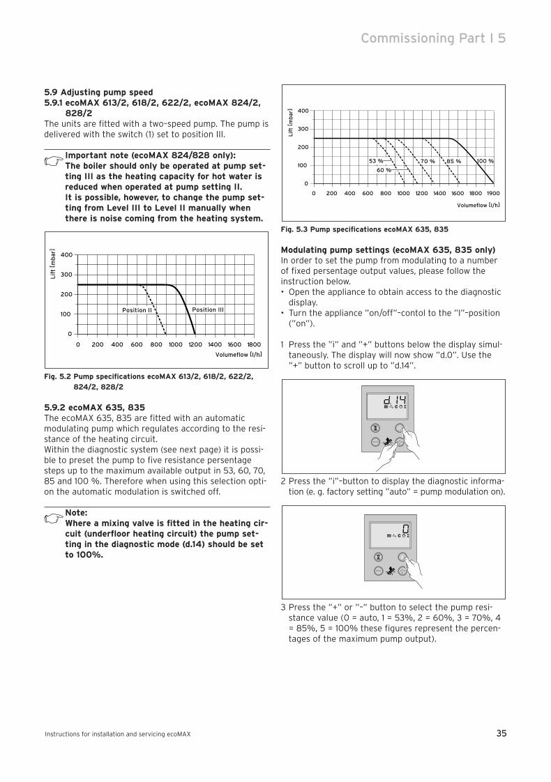
35
Commissioning Part I 5
Instructions for installation and servicing ecoMAX 35
5.9 Adjusting pump speed5.9.1 ecoMAX 613/2, 618/2, 622/2, ecoMAX 824/2,
828/2The units are fitted with a two–speed pump. The pump isdelivered with the switch (1) set to position III.
Important note (ecoMAX 824/828 only):The boiler should only be operated at pump set-ting III as the heating capacity for hot water isreduced when operated at pump setting II.It is possible, however, to change the pump set-ting from Level III to Level II manually whenthere is noise coming from the heating system.
Fig. 5.2 Pump specifications ecoMAX 613/2, 618/2, 622/2,
824/2, 828/2
5.9.2 ecoMAX 635, 835The ecoMAX 635, 835 are fitted with an automaticmodulating pump which regulates according to the resi-stance of the heating circuit.Within the diagnostic system (see next page) it is possi-ble to preset the pump to five resistance persentagesteps up to the maximum available output in 53, 60, 70,85 and 100 %. Therefore when using this selection opti-on the automatic modulation is switched off.
Note:Where a mixing valve is fitted in the heating cir-cuit (underfloor heating circuit) the pump set-ting in the diagnostic mode (d.14) should be setto 100%.
Fig. 5.3 Pump specifications ecoMAX 635, 835
Modulating pump settings (ecoMAX 635, 835 only)In order to set the pump from modulating to a numberof fixed persentage output values, please follow theinstruction below.• Open the appliance to obtain access to the diagnostic
display.• Turn the appliance ”on/off”–contol to the ”I”–position
(”on”).
1 Press the ”i” and ”+” buttons below the display simul-taneously. The display will now show ”d.0”. Use the”+” button to scroll up to ”d.14”.
2 Press the ”i”–button to display the diagnostic informa-tion (e. g. factory setting ”auto” = pump modulation on).
3 Press the ”+” or ”–” button to select the pump resi-stance value (0 = auto, 1 = 53%, 2 = 60%, 3 = 70%, 4= 85%, 5 = 100% these figures represent the percen-tages of the maximum pump output).
400
300
200
100
0
0 200 400 600 800 1000 1200 1600
Lif
t [ m
bar
]
1800
Volumeflow [l/h]
19001400
100 %53 %
60 %
70 % 85 %
400
300
200
100
0
0 200 400 600 800 1000 1200 1600
Lif
t [ m
bar
]
18001400
Position IIIPosition II
Volumeflow [l/h]
83 41 77_12 GB04.04.qxd 22.09.2004 12:34 Uhr Seite 35

36
5 Commissioning Part I
Instructions for installation and servicing ecoMAX36
When altering values the display will flash.
4 Press and hold the ”i”–button to save the requiredvalue to memory. When the value is saved, the displaywill stop flashing.
5 Diagnostic mode is cancelled as follows: Press the ”i” and ”+”–buttons simultaneouslyor Do not press any key for approximately four minu-tes. The display will now return to its normal state(current heating–system flow temperature, e.g. 45°C).
≈ 5 sec
Appliance Maximum net heat input Maximum gas rate Maximum gas rate
in kW Natural gas in m3/h Propane in kg/h
ecoMAX 613/2 E 13.5 1.43 1.05
ecoMAX 618/2 E 18.4 1.95 1.43
ecoMAX 622/2 E 22.4 2.37 1.74
ecoMAX 635 34.9 3.70 2.70
ecoMAX 824/2 E 23.0 2.43 1.78
ecoMAX 828/2 E 28.0 2.96 2.18
ecoMAX 835 E 35.0 3.70 2.70
Tab. 5.1 Maximum gas rates.
83 41 77_12 GB04.04.qxd 22.09.2004 12:34 Uhr Seite 36
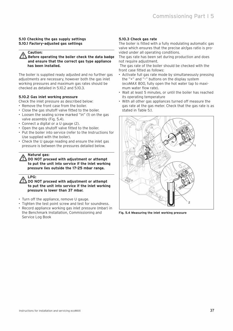
37
Commissioning Part I 5
Instructions for installation and servicing ecoMAX 37
5.10 Checking the gas supply settings5.10.1 Factory–adjusted gas settings
Caution:Before operating the boiler check the data badgeand ensure that the correct gas type appliancehas been installed.
The boiler is supplied ready adjusted and no further gasadjustments are necessary, however both the gas inletworking pressures and maximum gas rates should bechecked as detailed in 5.10.2 and 5.10.3.
5.10.2 Gas inlet working pressureCheck the inlet pressure as described below:• Remove the front case from the boiler.• Close the gas shutoff valve fitted to the boiler.• Loosen the sealing screw marked ”in” (1) on the gas
valve assembly (Fig. 5.4).• Connect a digital or a U gauge (2).• Open the gas shutoff valve fitted to the boiler.• Put the boiler into service (refer to the Instructions for
Use supplied with the boiler).• Check the U gauge reading and ensure the inlet gas
pressure is between the pressures detailed below.
Natural gas:DO NOT proceed with adjustment or attempt to put the unit into service if the inlet workingpressure lies outside the 17–25 mbar range.
LPG:DO NOT proceed with adjustment or attempt to put the unit into service if the inlet workingpressure is lower than 37 mbar.
• Turn off the appliance, remove U gauge.• Tighten the test point screw and test for soundness.• Record appliance working gas inlet pressure (mbar) in
the Benchmark Installation, Commissioning andService Log Book
5.10.3 Check gas rate The boiler is fitted with a fully modulating automatic gasvalve which ensures that the precise air/gas ratio is pro-vided under all operating conditions.The gas rate has been set during production and doesnot require adjustment.The gas rate of the boiler should be checked with the
front case fitted as follows:• Activate full gas rate mode by simultaneously pressing
the ”+” and ”–” buttons on the display system(ecoMAX 800, fully open the hot water tap to maxi-mum water flow rate).
• Wait at least 5 minutes, or until the boiler has reachedits operating temperature
• With all other gas appliances turned off measure thegas rate at the gas meter. Check that the gas rate is asstated in Table 5.1.
Fig. 5.4 Measuring the inlet working pressure
1
2
83 41 77_12 GB04.04.qxd 22.09.2004 12:34 Uhr Seite 37
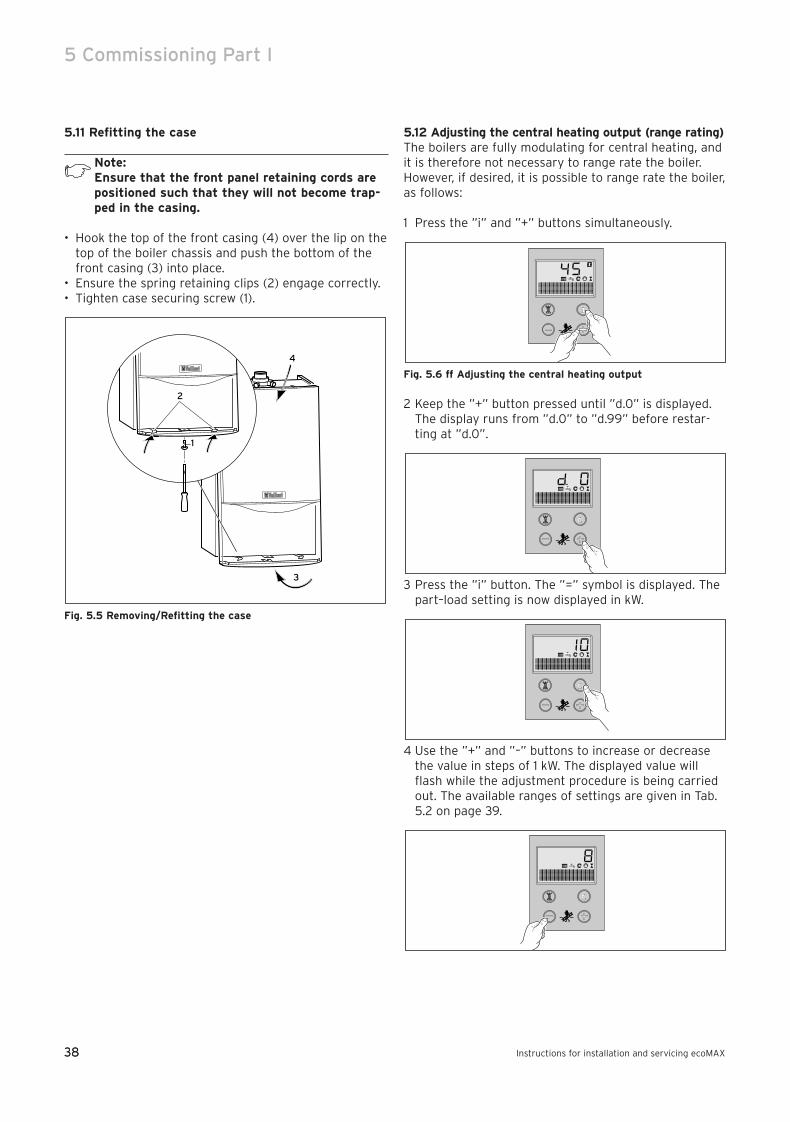
38
5 Commissioning Part I
Instructions for installation and servicing ecoMAX38
5.11 Refitting the case
Note: Ensure that the front panel retaining cords arepositioned such that they will not become trap-ped in the casing.
• Hook the top of the front casing (4) over the lip on thetop of the boiler chassis and push the bottom of thefront casing (3) into place.
• Ensure the spring retaining clips (2) engage correctly.• Tighten case securing screw (1).
Fig. 5.5 Removing/Refitting the case
5.12 Adjusting the central heating output (range rating)The boilers are fully modulating for central heating, andit is therefore not necessary to range rate the boiler.However, if desired, it is possible to range rate the boiler,as follows:
1 Press the ”i” and ”+” buttons simultaneously.
Fig. 5.6 ff Adjusting the central heating output
2 Keep the ”+” button pressed until ”d.0” is displayed.The display runs from ”d.0” to ”d.99” before restar-ting at ”d.0”.
3 Press the ”i” button. The ”=” symbol is displayed. Thepart–load setting is now displayed in kW.
4 Use the ”+” and ”–” buttons to increase or decreasethe value in steps of 1 kW. The displayed value willflash while the adjustment procedure is being carriedout. The available ranges of settings are given in Tab.5.2 on page 39.
3
1
2
4
83 41 77_12 GB04.04.qxd 22.09.2004 12:34 Uhr Seite 38
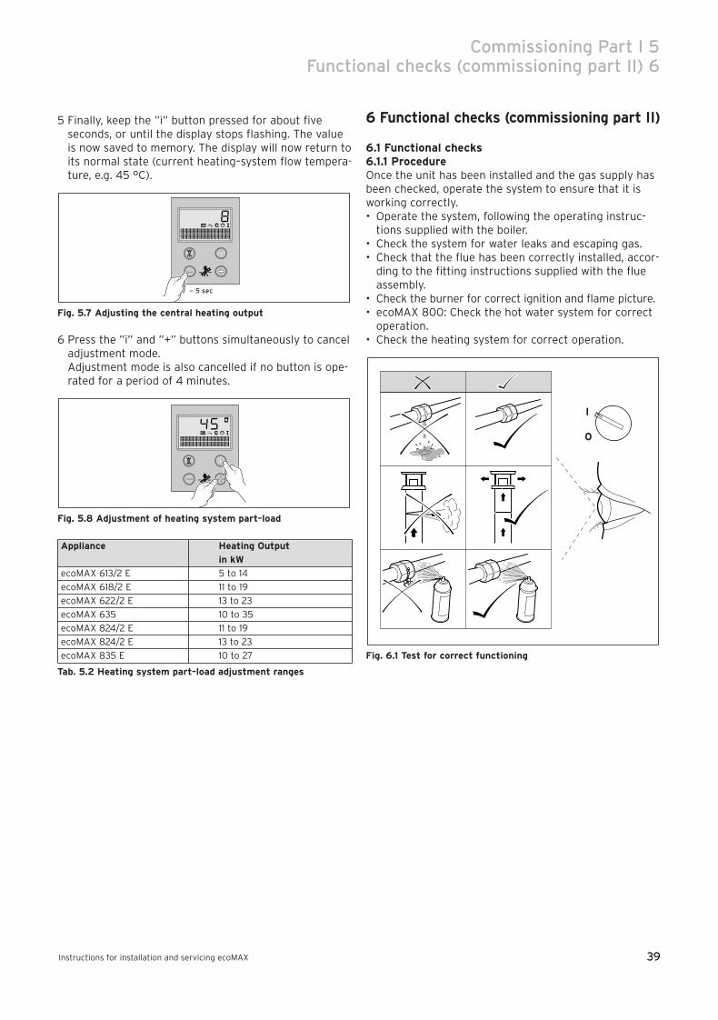
39
Commissioning Part I 5 Functional checks (commissioning part II) 6
Instructions for installation and servicing ecoMAX 39
5 Finally, keep the ”i” button pressed for about fiveseconds, or until the display stops flashing. The valueis now saved to memory. The display will now return toits normal state (current heating–system flow tempera-ture, e.g. 45 °C).
Fig. 5.7 Adjusting the central heating output
6 Press the ”i” and ”+” buttons simultaneously to canceladjustment mode.Adjustment mode is also cancelled if no button is ope-rated for a period of 4 minutes.
Fig. 5.8 Adjustment of heating system part–load
Appliance Heating Output
in kW
ecoMAX 613/2 E 5 to 14
ecoMAX 618/2 E 11 to 19
ecoMAX 622/2 E 13 to 23
ecoMAX 635 10 to 35
ecoMAX 824/2 E 11 to 19
ecoMAX 824/2 E 13 to 23
ecoMAX 835 E 10 to 27
Tab. 5.2 Heating system part–load adjustment ranges
6 Functional checks (commissioning part II)
6.1 Functional checks6.1.1 ProcedureOnce the unit has been installed and the gas supply hasbeen checked, operate the system to ensure that it isworking correctly. • Operate the system, following the operating instruc-
tions supplied with the boiler.• Check the system for water leaks and escaping gas.• Check that the flue has been correctly installed, accor-
ding to the fitting instructions supplied with the flueassembly.
• Check the burner for correct ignition and flame picture.• ecoMAX 800: Check the hot water system for correct
operation.• Check the heating system for correct operation.
Fig. 6.1 Test for correct functioning
I
0
≈ 5 sec
83 41 77_12 GB04.04.qxd 22.09.2004 12:34 Uhr Seite 39
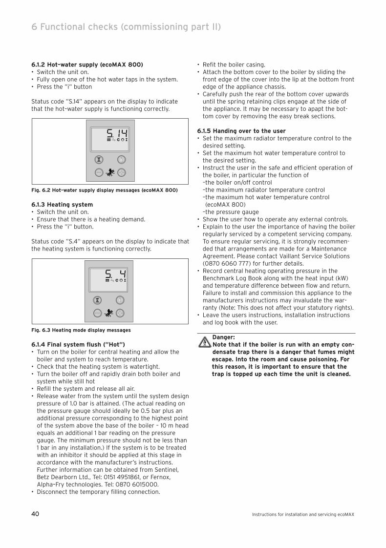
40
6 Functional checks (commissioning part II)
Instructions for installation and servicing ecoMAX40
6.1.2 Hot–water supply (ecoMAX 800)• Switch the unit on.• Fully open one of the hot water taps in the system.• Press the ”i” button
Status code ”S.14” appears on the display to indicatethat the hot–water supply is functioning correctly.
Fig. 6.2 Hot–water supply display messages (ecoMAX 800)
6.1.3 Heating system• Switch the unit on.• Ensure that there is a heating demand.• Press the ”i” button.
Status code ”S.4” appears on the display to indicate thatthe heating system is functioning correctly.
Fig. 6.3 Heating mode display messages
6.1.4 Final system flush (”Hot”)• Turn on the boiler for central heating and allow the
boiler and system to reach temperature. • Check that the heating system is watertight. • Turn the boiler off and rapidly drain both boiler and
system while still hot• Refill the system and release all air. • Release water from the system until the system design
pressure of 1.0 bar is attained. (The actual reading onthe pressure gauge should ideally be 0.5 bar plus anadditional pressure corresponding to the highest point of the system above the base of the boiler – 10 m headequals an additional 1 bar reading on the pressuregauge. The minimum pressure should not be less than1 bar in any installation.) If the system is to be treatedwith an inhibitor it should be applied at this stage inaccordance with the manufacturer’s instructions.Further information can be obtained from Sentinel,Betz Dearborn Ltd., Tel: 0151 4951861, or Fernox,Alpha–Fry technologies. Tel: 0870 6015000.
• Disconnect the temporary filling connection.
• Refit the boiler casing. • Attach the bottom cover to the boiler by sliding the
front edge of the cover into the lip at the bottom frontedge of the appliance chassis.
• Carefully push the rear of the bottom cover upwardsuntil the spring retaining clips engage at the side ofthe appliance. It may be necessary to apapt the bot-tom cover by removing the easy break sections.
6.1.5 Handing over to the user• Set the maximum radiator temperature control to the
desired setting.• Set the maximum hot water temperature control to
the desired setting.• Instruct the user in the safe and efficient operation of
the boiler, in particular the function of–the boiler on/off control–the maximum radiator temperature control–the maximum hot water temperature control(ecoMAX 800)
–the pressure gauge• Show the user how to operate any external controls.• Explain to the user the importance of having the boiler
regularly serviced by a competent servicing company.To ensure regular servicing, it is strongly recommen-ded that arrangements are made for a MaintenanceAgreement. Please contact Vaillant Service Solutions(0870 6060 777) for further details.
• Record central heating operating pressure in theBenchmark Log Book along with the heat input (kW)and temperature difference between flow and return. Failure to install and commission this appliance to themanufacturers instructions may invaludate the war-ranty (Note: This does not affect your statutory rights).
• Leave the users instructions, installation instructionsand log book with the user.
Danger:Note that if the boiler is run with an empty con-densate trap there is a danger that fumes mightescape. Into the room and cause poisoning. Forthis reason, it is important to ensure that thetrap is topped up each time the unit is cleaned.
83 41 77_12 GB04.04.qxd 22.09.2004 12:34 Uhr Seite 40
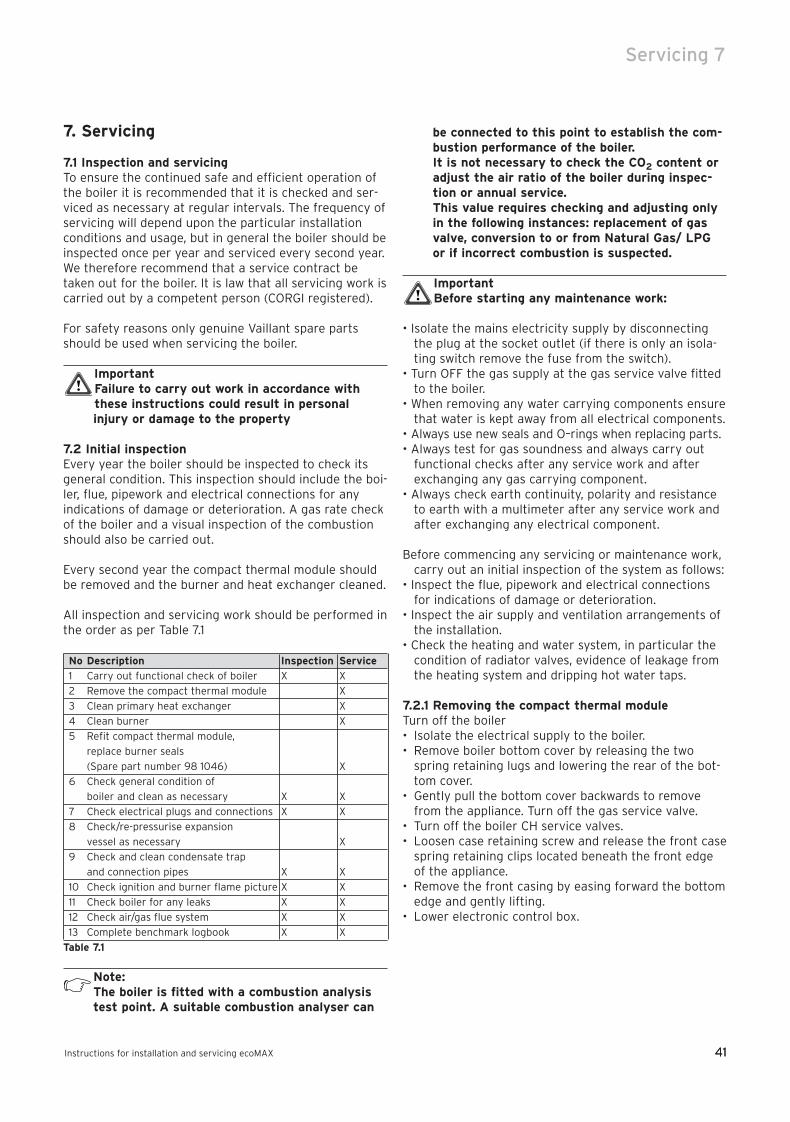
41
Servicing 7
Instructions for installation and servicing ecoMAX 41
7. Servicing
7.1 Inspection and servicingTo ensure the continued safe and efficient operation ofthe boiler it is recommended that it is checked and ser-viced as necessary at regular intervals. The frequency ofservicing will depend upon the particular installationconditions and usage, but in general the boiler should beinspected once per year and serviced every second year.We therefore recommend that a service contract betaken out for the boiler. It is law that all servicing work iscarried out by a competent person (CORGI registered).
For safety reasons only genuine Vaillant spare partsshould be used when servicing the boiler.
ImportantFailure to carry out work in accordance withthese instructions could result in personalinjury or damage to the property
7.2 Initial inspectionEvery year the boiler should be inspected to check itsgeneral condition. This inspection should include the boi-ler, flue, pipework and electrical connections for anyindications of damage or deterioration. A gas rate checkof the boiler and a visual inspection of the combustionshould also be carried out.
Every second year the compact thermal module shouldbe removed and the burner and heat exchanger cleaned.
All inspection and servicing work should be performed inthe order as per Table 7.1
No Description Inspection Service
1 Carry out functional check of boiler X X
2 Remove the compact thermal module X
3 Clean primary heat exchanger X
4 Clean burner X
5 Refit compact thermal module,
replace burner seals
(Spare part number 98 1046) X
6 Check general condition of
boiler and clean as necessary X X
7 Check electrical plugs and connections X X
8 Check/re-pressurise expansion
vessel as necessary X
9 Check and clean condensate trap
and connection pipes X X
10 Check ignition and burner flame picture X X
11 Check boiler for any leaks X X
12 Check air/gas flue system X X
13 Complete benchmark logbook X X
Table 7.1
Note: The boiler is fitted with a combustion analysistest point. A suitable combustion analyser can
be connected to this point to establish the com-bustion performance of the boiler. It is not necessary to check the CO2 content oradjust the air ratio of the boiler during inspec-tion or annual service.This value requires checking and adjusting onlyin the following instances: replacement of gasvalve, conversion to or from Natural Gas/ LPGor if incorrect combustion is suspected.
ImportantBefore starting any maintenance work:
• Isolate the mains electricity supply by disconnectingthe plug at the socket outlet (if there is only an isola-ting switch remove the fuse from the switch).
• Turn OFF the gas supply at the gas service valve fittedto the boiler.
• When removing any water carrying components ensurethat water is kept away from all electrical components.
• Always use new seals and O–rings when replacing parts.• Always test for gas soundness and always carry out
functional checks after any service work and afterexchanging any gas carrying component.
• Always check earth continuity, polarity and resistanceto earth with a multimeter after any service work andafter exchanging any electrical component.
Before commencing any servicing or maintenance work,carry out an initial inspection of the system as follows:
• Inspect the flue, pipework and electrical connectionsfor indications of damage or deterioration.
• Inspect the air supply and ventilation arrangements ofthe installation.
• Check the heating and water system, in particular thecondition of radiator valves, evidence of leakage fromthe heating system and dripping hot water taps.
7.2.1 Removing the compact thermal moduleTurn off the boiler• Isolate the electrical supply to the boiler.• Remove boiler bottom cover by releasing the two
spring retaining lugs and lowering the rear of the bot-tom cover.
• Gently pull the bottom cover backwards to removefrom the appliance. Turn off the gas service valve.
• Turn off the boiler CH service valves.• Loosen case retaining screw and release the front case
spring retaining clips located beneath the front edgeof the appliance.
• Remove the front casing by easing forward the bottomedge and gently lifting.
• Lower electronic control box.
83 41 77_12 GB04.04.qxd 22.09.2004 12:34 Uhr Seite 41
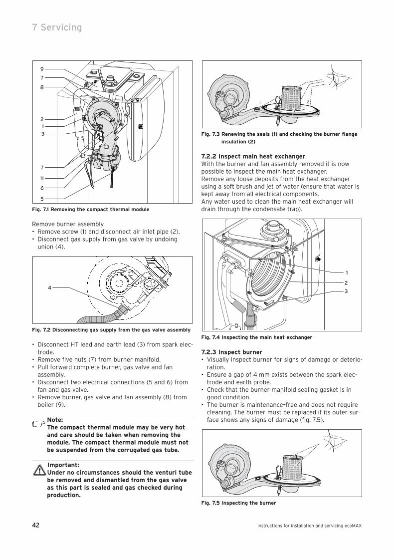
42
7 Servicing
Instructions for installation and servicing ecoMAX42
Fig. 7.1 Removing the compact thermal module
Remove burner assembly• Remove screw (1) and disconnect air inlet pipe (2).• Disconnect gas supply from gas valve by undoing
union (4).
Fig. 7.2 Disconnecting gas supply from the gas valve assembly
• Disconnect HT lead and earth lead (3) from spark elec-trode.
• Remove five nuts (7) from burner manifold.• Pull forward complete burner, gas valve and fan
assembly.• Disconnect two electrical connections (5 and 6) from
fan and gas valve.• Remove burner, gas valve and fan assembly (8) from
boiler (9).
Note: The compact thermal module may be very hotand care should be taken when removing themodule. The compact thermal module must notbe suspended from the corrugated gas tube.
Important: Under no circumstances should the venturi tubebe removed and dismantled from the gas valveas this part is sealed and gas checked duringproduction.
Fig. 7.3 Renewing the seals (1) and checking the burner flange
insulation (2)
7.2.2 Inspect main heat exchangerWith the burner and fan assembly removed it is nowpossible to inspect the main heat exchanger.Remove any loose deposits from the heat exchangerusing a soft brush and jet of water (ensure that water iskept away from all electrical components.Any water used to clean the main heat exchanger willdrain through the condensate trap).
Fig. 7.4 Inspecting the main heat exchanger
7.2.3 Inspect burner• Visually inspect burner for signs of damage or deterio-
ration.• Ensure a gap of 4 mm exists between the spark elec-
trode and earth probe.• Check that the burner manifold sealing gasket is in
good condition.• The burner is maintenance–free and does not require
cleaning. The burner must be replaced if its outer sur-face shows any signs of damage (fig. 7.5).
Fig. 7.5 Inspecting the burner
1
1
3
2
1
1
2
4
12
7
8
9
3
7
11
6
5
83 41 77_12 GB04.04.qxd 22.09.2004 12:34 Uhr Seite 42
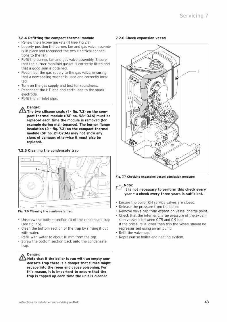
43
Servicing 7
Instructions for installation and servicing ecoMAX 43
7.2.4 Refitting the compact thermal module• Renew the silicone gaskets (1) (see Fig 7.3)• Loosely position the burner, fan and gas valve assemb-
ly in place and reconnect the two electrical connec-tions to the fan.
• Refit the burner, fan and gas valve assembly. Ensurethat the burner manifold gasket is correctly fitted andthat a good seal is obtained.
• Reconnect the gas supply to the gas valve, ensuringthat a new sealing washer is used and correctly loca-ted.
• Turn on the gas supply and test for soundness.• Reconnect the HT lead and earth lead to the spark
electrode.• Refit the air inlet pipe.
Danger:The two silicone seals (1 - fig. 7.3) on the com-pact thermal module ((SP no. 98-1046) must bereplaced each time the module is removed (forexample during maintenance). The burner flangeinsulation (2 - fig. 7.3) on the compact thermalmodule (SP no. 21-0734) may not show anysigns of damage; otherwise it must also bereplaced.
7.2.5 Cleaning the condensate trap
Fig. 7.6 Cleaning the condensate trap
• Unscrew the bottom section (1) of the condensate trap(see fig. 7.6).
• Clean the bottom section of the trap by rinsing it outwith water.
• Refill with water to about 10 mm from the top.• Screw the bottom section back onto the condensate
trap.
Danger:Note that if the boiler is run with an empty con-densate trap there is a danger that fumes mightescape into the room and cause poisoning. Forthis reason, it is important to ensure that thetrap is topped up each time the unit is cleaned.
7.2.6 Check expansion vessel
Fig. 7.7 Checking expansion vessel admission pressure
Note:It is not necessary to perform this check everyyear – a check every three years is sufficient.
• Ensure the boiler CH service valves are closed.• Release the pressure from the boiler.• Remove valve cap from expansion vessel charge point.• Check that the internal charge pressure of the expan-
sion vessel is between 0.75 and 0.9 bar. If the pressure is lower than this the vessel should berepressurised using an air pump.
• Refit the valve cap.• Repressurise boiler and heating system.
1
1
83 41 77_12 GB04.04.qxd 22.09.2004 12:34 Uhr Seite 43
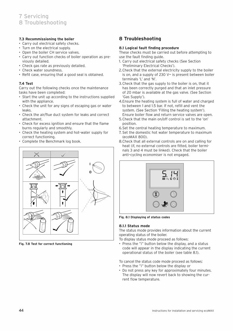
44
7 Servicing8 Troubleshooting
Instructions for installation and servicing ecoMAX44
7.3 Recommissioning the boiler• Carry out electrical safety checks.• Turn on the electrical supply.• Open the boiler CH service valves.• Carry out function checks of boiler operation as pre-
viously detailed.• Check gas rate as previously detailed.• Check water soundness.• Refit case, ensuring that a good seal is obtained.
7.4 Test Carry out the following checks once the maintenancetasks have been completed:• Start the unit up according to the instructions supplied
with the appliance.• Check the unit for any signs of escaping gas or water
leaks.• Check the air/flue duct system for leaks and correct
attachment.• Check for excess ignition and ensure that the flame
burns regularly and smoothly.• Check the heating system and hot–water supply for
correct functioning.• Complete the Benchmark log book.
Fig. 7.8 Test for correct functioning
8 Troubleshooting
8.1 Logical fault finding procedureThese checks must be carried out before attempting touse the fault finding guide.1. Carry out electrical safety checks (See Section
‘Preliminary Electrical Checks’).2.Check that the external electricity supply to the boiler
is on, and a supply of 230 V~ is present between boilerterminals ‘L’ and ‘N’.
3.Check that the gas supply to the boiler is on, that ithas been correctly purged and that an inlet pressureof 20 mbar is available at the gas valve. (See Section‘Gas Supply’).
4.Ensure the heating system is full of water and chargedto between 1 and 1.5 bar. If not, refill and vent thesystem. (See Section ‘Filling the heating system’).Ensure boiler flow and return service valves are open.
5.Check that the main on/off control is set to the ‘on’position.
6.Set the central heating temperature to maximum. 7. Set the domestic hot water temperature to maximum
(ecoMAX 800).8.Check that all external controls are on and calling for
heat (if, no external controls are fitted, boiler termi-nals 3 and 4 must be linked). Check that the boileranti–cycling economiser is not engaged.
Fig. 8.1 Displaying of status codes
8.1.1 Status modeThe status mode provides information about the currentoperating status of the boiler.To display status mode proceed as follows:• Press the ”i” button below the display, and a status
code will appear in the display indicating the currentoperational status of the boiler (see table 8.1).
To cancel the status code mode proceed as follows:• Press the ”i” button below the display or• Do not press any key for approximately four minutes.
The display will now revert back to showing the cur-rent flow temperature.
I
0
83 41 77_12 GB04.04.qxd 22.09.2004 12:34 Uhr Seite 44
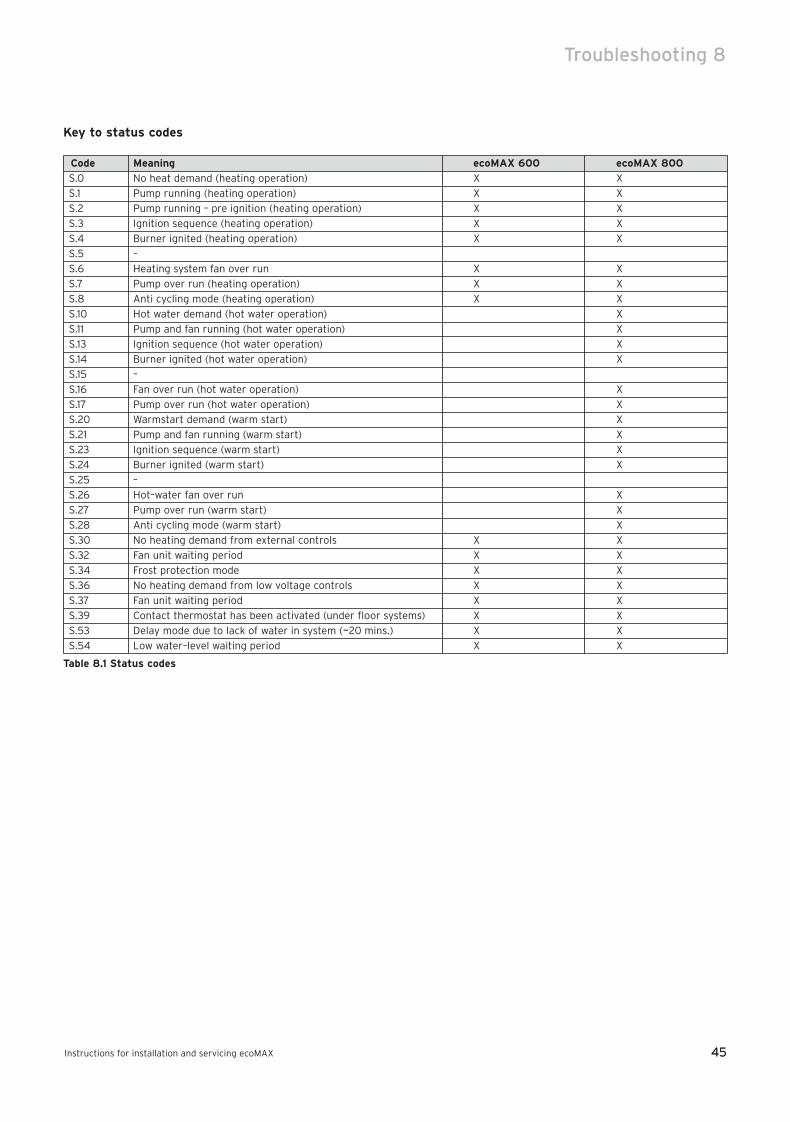
45
Troubleshooting 8
Instructions for installation and servicing ecoMAX 45
Key to status codes
Code Meaning ecoMAX 600 ecoMAX 800
S.0 No heat demand (heating operation) X X
S.1 Pump running (heating operation) X X
S.2 Pump running – pre ignition (heating operation) X X
S.3 Ignition sequence (heating operation) X X
S.4 Burner ignited (heating operation) X X
S.5 –
S.6 Heating system fan over run X X
S.7 Pump over run (heating operation) X X
S.8 Anti cycling mode (heating operation) X X
S.10 Hot water demand (hot water operation) X
S.11 Pump and fan running (hot water operation) X
S.13 Ignition sequence (hot water operation) X
S.14 Burner ignited (hot water operation) X
S.15 –
S.16 Fan over run (hot water operation) X
S.17 Pump over run (hot water operation) X
S.20 Warmstart demand (warm start) X
S.21 Pump and fan running (warm start) X
S.23 Ignition sequence (warm start) X
S.24 Burner ignited (warm start) X
S.25 –
S.26 Hot–water fan over run X
S.27 Pump over run (warm start) X
S.28 Anti cycling mode (warm start) X
S.30 No heating demand from external controls X X
S.32 Fan unit waiting period X X
S.34 Frost protection mode X X
S.36 No heating demand from low voltage controls X X
S.37 Fan unit waiting period X X
S.39 Contact thermostat has been activated (under floor systems) X X
S.53 Delay mode due to lack of water in system (~20 mins.) X X
S.54 Low water–level waiting period X X
Table 8.1 Status codes
83 41 77_12 GB04.04.qxd 22.09.2004 12:34 Uhr Seite 45
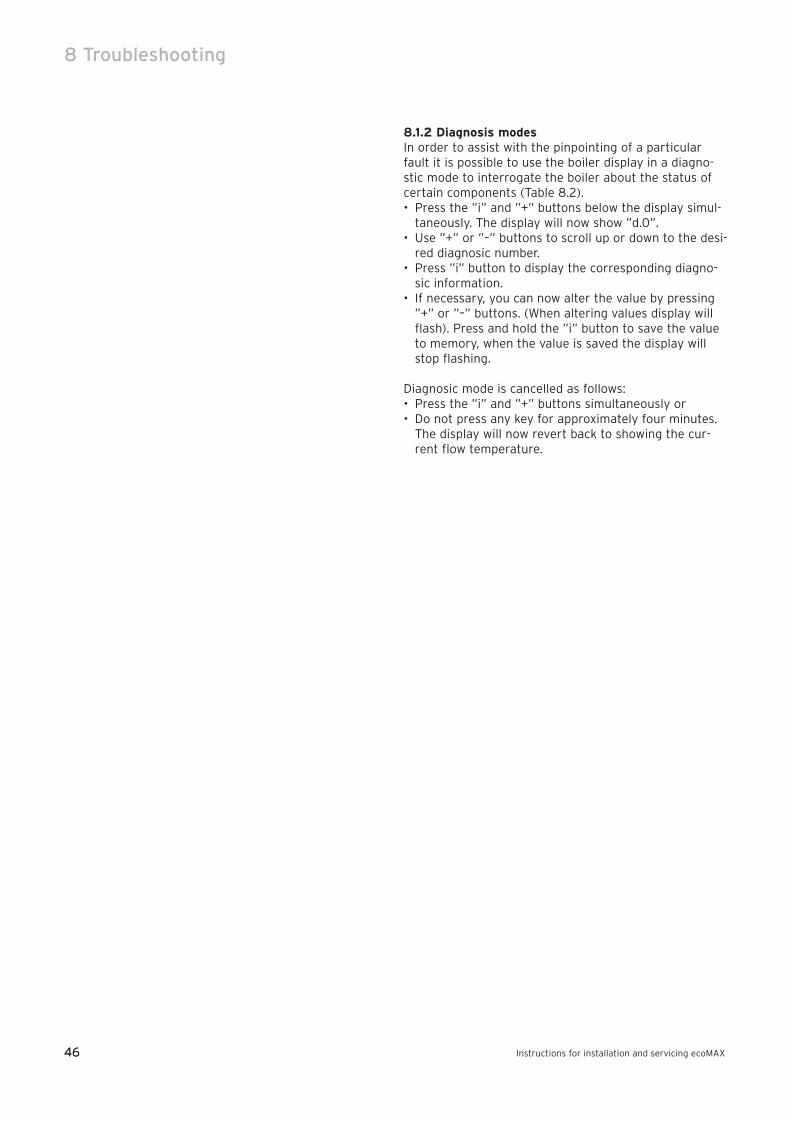
46
8 Troubleshooting
Instructions for installation and servicing ecoMAX46
8.1.2 Diagnosis modesIn order to assist with the pinpointing of a particularfault it is possible to use the boiler display in a diagno-stic mode to interrogate the boiler about the status ofcertain components (Table 8.2).• Press the ”i” and ”+” buttons below the display simul-
taneously. The display will now show ”d.0”.• Use ”+” or ”–” buttons to scroll up or down to the desi-
red diagnosic number.• Press ”i” button to display the corresponding diagno-
sic information.• If necessary, you can now alter the value by pressing
”+” or ”–” buttons. (When altering values display willflash). Press and hold the ”i” button to save the valueto memory, when the value is saved the display willstop flashing.
Diagnosic mode is cancelled as follows:• Press the ”i” and ”+” buttons simultaneously or• Do not press any key for approximately four minutes.
The display will now revert back to showing the cur-rent flow temperature.
83 41 77_12 GB04.04.qxd 22.09.2004 12:34 Uhr Seite 46
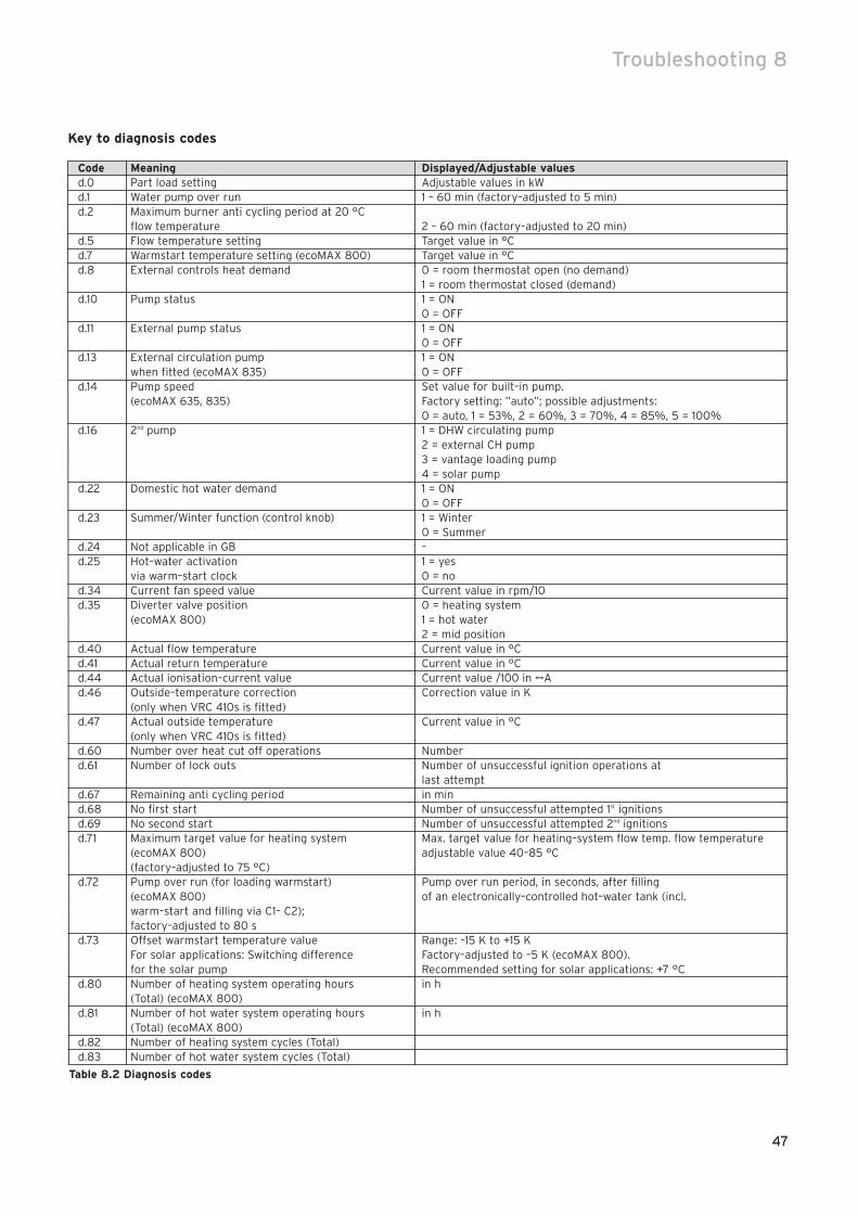
47
Troubleshooting 8
47
Key to diagnosis codes
Code Meaning Displayed/Adjustable valuesd.0 Part load setting Adjustable values in kWd.1 Water pump over run 1 – 60 min (factory–adjusted to 5 min)d.2 Maximum burner anti cycling period at 20 °C
flow temperature 2 – 60 min (factory–adjusted to 20 min)d.5 Flow temperature setting Target value in °Cd.7 Warmstart temperature setting (ecoMAX 800) Target value in °Cd.8 External controls heat demand 0 = room thermostat open (no demand)
1 = room thermostat closed (demand) d.10 Pump status 1 = ON
0 = OFFd.11 External pump status 1 = ON
0 = OFFd.13 External circulation pump 1 = ON
when fitted (ecoMAX 835) 0 = OFFd.14 Pump speed Set value for built–in pump.
(ecoMAX 635, 835) Factory setting: ”auto”; possible adjustments:0 = auto, 1 = 53%, 2 = 60%, 3 = 70%, 4 = 85%, 5 = 100%
d.16 2nd pump 1 = DHW circulating pump2 = external CH pump3 = vantage loading pump4 = solar pump
d.22 Domestic hot water demand 1 = ON0 = OFF
d.23 Summer/Winter function (control knob) 1 = Winter0 = Summer
d.24 Not applicable in GB –d.25 Hot–water activation 1 = yes
via warm–start clock 0 = nod.34 Current fan speed value Current value in rpm/10d.35 Diverter valve position 0 = heating system
(ecoMAX 800) 1 = hot water2 = mid position
d.40 Actual flow temperature Current value in °Cd.41 Actual return temperature Current value in °Cd.44 Actual ionisation–current value Current value /100 in µAd.46 Outside–temperature correction Correction value in K
(only when VRC 410s is fitted)d.47 Actual outside temperature Current value in °C
(only when VRC 410s is fitted)d.60 Number over heat cut off operations Numberd.61 Number of lock outs Number of unsuccessful ignition operations at
last attemptd.67 Remaining anti cycling period in mind.68 No first start Number of unsuccessful attempted 1st ignitionsd.69 No second start Number of unsuccessful attempted 2nd ignitionsd.71 Maximum target value for heating system Max. target value for heating–system flow temp. flow temperature
(ecoMAX 800) adjustable value 40–85 °C (factory–adjusted to 75 °C)
d.72 Pump over run (for loading warmstart) Pump over run period, in seconds, after filling (ecoMAX 800) of an electronically–controlled hot–water tank (incl. warm–start and filling via C1– C2); factory–adjusted to 80 s
d.73 Offset warmstart temperature value Range: –15 K to +15 KFor solar applications: Switching difference Factory–adjusted to –5 K (ecoMAX 800).for the solar pump Recommended setting for solar applications: +7 °C
d.80 Number of heating system operating hours in h(Total) (ecoMAX 800)
d.81 Number of hot water system operating hours in h(Total) (ecoMAX 800)
d.82 Number of heating system cycles (Total)d.83 Number of hot water system cycles (Total)
Table 8.2 Diagnosis codes
83 41 77_12 GB04.04.qxd 22.09.2004 12:34 Uhr Seite 47

48
8 Troubleshooting
Instructions for installation and servicing ecoMAX48
8.1.3 Fault codesFault codes take priority over all other display functionsin the event of a system fault occurring (Table 8.3).If multiple faults occur, the corresponding fault codesare displayed alternately for about two seconds each.
8.1.4 Fault memoryThe fault memory stores details of the ten most recentfaults.• Press the ”i” and ”–” buttons simultaneously.• Use the ”+” button to scroll back through the list of
memorised errors.
To cancel fault error memory display mode, proceed asfollows:• Press the ”i” button below the display or• Do not touch any key for about four minutes. The dis-
play will now revert back to showing the current flowtemperature.
83 41 77_12 GB04.04.qxd 22.09.2004 12:34 Uhr Seite 48
49
Troubleshooting 8
Instructions for installation and servicing ecoMAX
49
Key to Fault codes
Code Meaning Cause
F.0 Flow–NTC:
– NTC broken
– NTC cable broken Flow–NTC cable defective/broken NTC faulty
– Defective connection at NTC
– Defective connection at electronics
F.1 Return–NTC:
– NTC broken
– NTC cable broken Return–NTC cable defective/broken NTC faulty
– Defective connection at NTC
– Defective connection at electronics
F.10 Short circuit – flow–NTC (< 130 °C) NTC– plug shorted to casing, NTC defective
F.11 Short circuit – return–NTC (< 130 °C) NTC– plug shorted to casing
NTC defective
F.13 Short circuit in tank sensor NTC defective, earth leak/short circuit in cable loom,
damp plug connection
F.20 Over heat cut off activated Maximum temperature exceeded
No water in system
F.22 Low water or no water in appliance Pump defective
Pump lead defective
F.23 Water level low Pump obstructed, pump running at lower capacity,
Temperature range too wide Air in appliance, system pressure too low,
flow and backflow NTC reversed
F.24 Water level low Pump obstructed, pump running at lower capacity,
Temperature rises too fast ir in appliance, system pressure too low,
flow and backflow NTC reversed
F.25 Water Switch Water Switch - plug disconnected
System pressure too low Waterswitch activated
F.27 No demand to gas valve Electronic board defective
Gas valve defective
No gas
Insufficient gas
Incorrect gas valve adjustment
F.28 Boiler goes to lock out Electrode defective
Ignition lead defect
Electronic igniter defective
Check air inlet duct
F.29 Flame extinguished re–ignition unsuccessful Gas supply absent or insufficient
Check flue duct
F.32 Fan turning–speed malfunction Fan unit obstructed, plug–in fan connector not
(too fast at start–up) correctly inserted, Hall sensor defective, fault in cable
loom, defective electronic control system
F.60 Gas–valve control + defective Short circuit/earth (ground) leak in cable loom to gas
valves, gas valve assembly defective (earth/ground
leak from coils), electronic control system defective
Short circuit/earth (ground) leak in cable loom to gas
F.61 Gas–valve control – defective valves, gas valve assembly defective (earth/ground
leak from coils), electronic control system defective
F.62 Defective gas–valve closure mechanism Leak in gas valve assembly, electronic fault
F.63 EEPROM error Electronic fault
F.64 Electronic system/sensor fault Short circuit in flow or backflow NTC,
electronic fault
F.65 Electronic system temperature too high Electronic system affected by external heat source,
electronic fault
F.67 Electronic fault in flame system Electronic fault
(non–plausible flame signal)
Table 8.3
83 41 77_12 GB04.04.qxd 22.09.2004 12:34 Uhr Seite 49
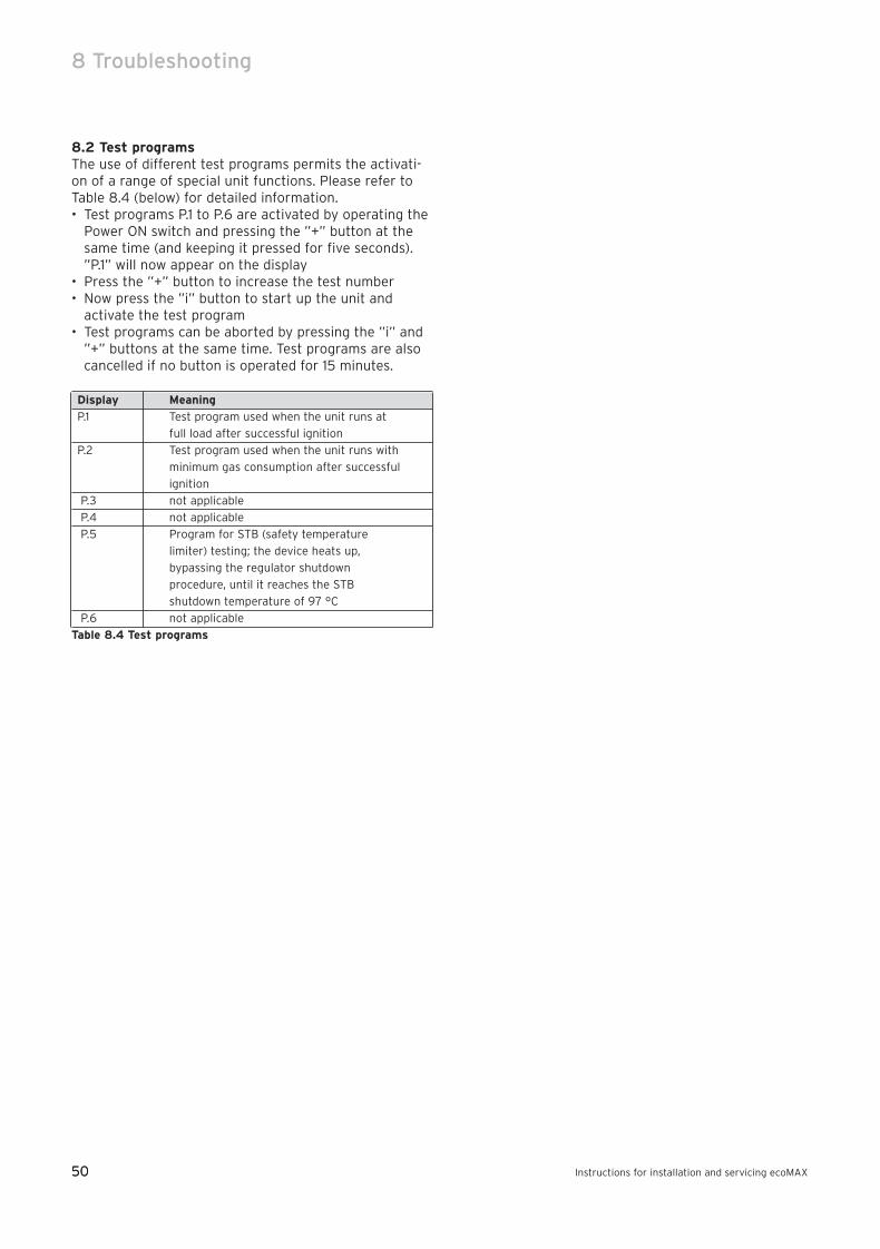
50
8 Troubleshooting
Instructions for installation and servicing ecoMAX50
8.2 Test programsThe use of different test programs permits the activati-on of a range of special unit functions. Please refer toTable 8.4 (below) for detailed information.• Test programs P.1 to P.6 are activated by operating the
Power ON switch and pressing the ”+” button at thesame time (and keeping it pressed for five seconds).”P.1” will now appear on the display
• Press the ”+” button to increase the test number• Now press the ”i” button to start up the unit and
activate the test program• Test programs can be aborted by pressing the ”i” and
”+” buttons at the same time. Test programs are alsocancelled if no button is operated for 15 minutes.
Display Meaning
P.1 Test program used when the unit runs at
full load after successful ignition
P.2 Test program used when the unit runs with
minimum gas consumption after successful
ignition
P.3 not applicable
P.4 not applicable
P.5 Program for STB (safety temperature
limiter) testing; the device heats up,
bypassing the regulator shutdown
procedure, until it reaches the STB
shutdown temperature of 97 °C
P.6 not applicable
Table 8.4 Test programs
83 41 77_12 GB04.04.qxd 22.09.2004 12:34 Uhr Seite 50
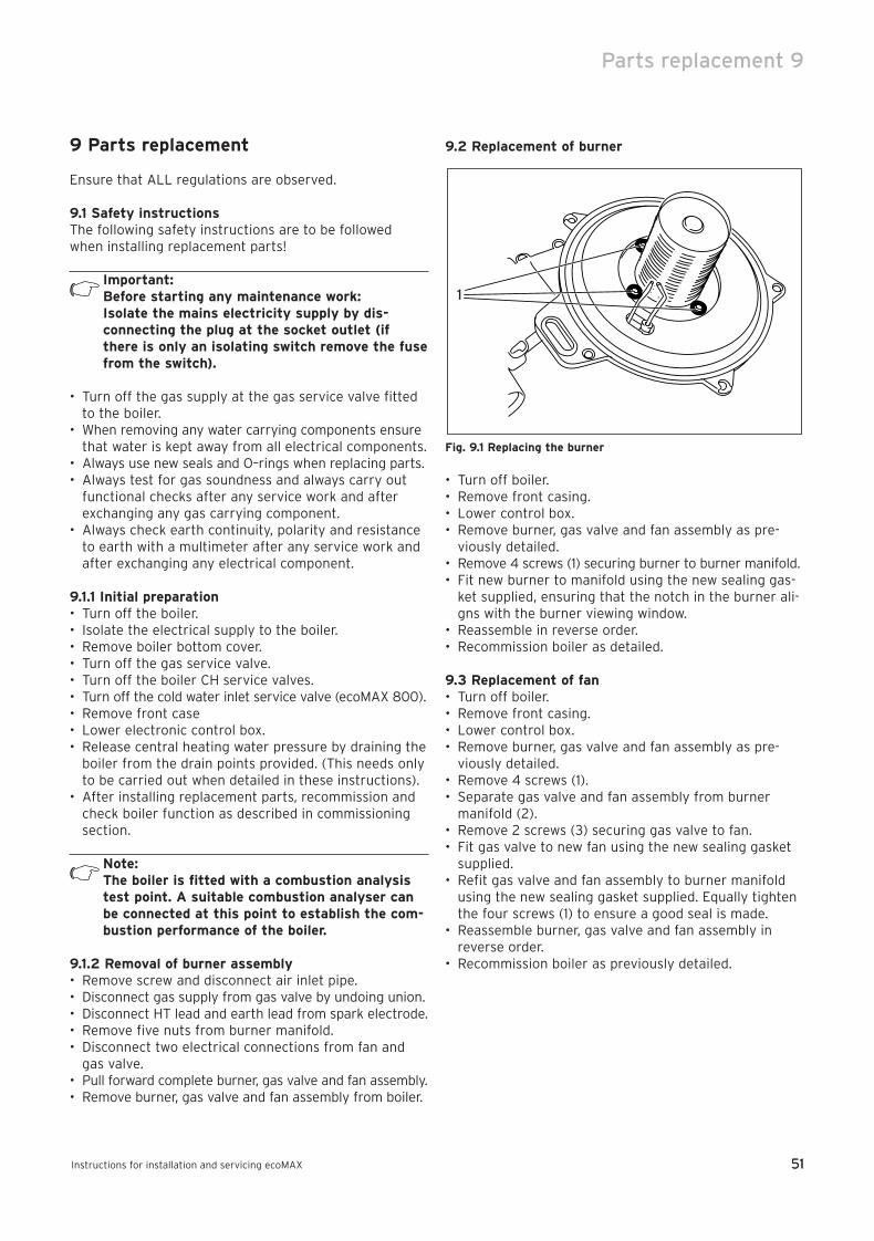
51
Parts replacement 9
Instructions for installation and servicing ecoMAX 51
9 Parts replacement
Ensure that ALL regulations are observed.
9.1 Safety instructionsThe following safety instructions are to be followedwhen installing replacement parts!
Important: Before starting any maintenance work:Isolate the mains electricity supply by dis-connecting the plug at the socket outlet (ifthere is only an isolating switch remove the fusefrom the switch).
• Turn off the gas supply at the gas service valve fittedto the boiler.
• When removing any water carrying components ensurethat water is kept away from all electrical components.
• Always use new seals and O–rings when replacing parts.• Always test for gas soundness and always carry out
functional checks after any service work and afterexchanging any gas carrying component.
• Always check earth continuity, polarity and resistanceto earth with a multimeter after any service work andafter exchanging any electrical component.
9.1.1 Initial preparation• Turn off the boiler.• Isolate the electrical supply to the boiler.• Remove boiler bottom cover.• Turn off the gas service valve.• Turn off the boiler CH service valves.• Turn off the cold water inlet service valve (ecoMAX 800).• Remove front case• Lower electronic control box. • Release central heating water pressure by draining the
boiler from the drain points provided. (This needs onlyto be carried out when detailed in these instructions).
• After installing replacement parts, recommission andcheck boiler function as described in commissioningsection.
Note: The boiler is fitted with a combustion analysistest point. A suitable combustion analyser canbe connected at this point to establish the com-bustion performance of the boiler.
9.1.2 Removal of burner assembly• Remove screw and disconnect air inlet pipe.• Disconnect gas supply from gas valve by undoing union.• Disconnect HT lead and earth lead from spark electrode.• Remove five nuts from burner manifold.• Disconnect two electrical connections from fan and
gas valve.• Pull forward complete burner, gas valve and fan assembly.• Remove burner, gas valve and fan assembly from boiler.
9.2 Replacement of burner
Fig. 9.1 Replacing the burner
• Turn off boiler.• Remove front casing.• Lower control box.• Remove burner, gas valve and fan assembly as pre-
viously detailed.• Remove 4 screws (1) securing burner to burner manifold.• Fit new burner to manifold using the new sealing gas-
ket supplied, ensuring that the notch in the burner ali-gns with the burner viewing window.
• Reassemble in reverse order.• Recommission boiler as detailed.
9.3 Replacement of fan • Turn off boiler.• Remove front casing.• Lower control box.• Remove burner, gas valve and fan assembly as pre-
viously detailed.• Remove 4 screws (1).• Separate gas valve and fan assembly from burner
manifold (2).• Remove 2 screws (3) securing gas valve to fan.• Fit gas valve to new fan using the new sealing gasket
supplied.• Refit gas valve and fan assembly to burner manifold
using the new sealing gasket supplied. Equally tightenthe four screws (1) to ensure a good seal is made.
• Reassemble burner, gas valve and fan assembly inreverse order.
• Recommission boiler as previously detailed.
1
83 41 77_12 GB04.04.qxd 22.09.2004 12:34 Uhr Seite 51
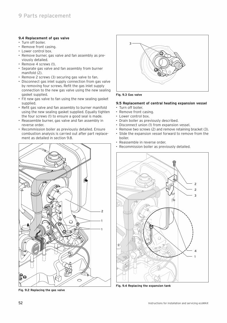
52
9 Parts replacement
Instructions for installation and servicing ecoMAX52
9.4 Replacement of gas valve • Turn off boiler.• Remove front casing.• Lower control box.• Remove burner, gas valve and fan assembly as pre-
viously detailed.• Remove 4 screws (1).• Separate gas valve and fan assembly from burner
manifold (2).• Remove 2 screws (3) securing gas valve to fan.• Disconnect gas inlet supply connection from gas valve
by removing four screws. Refit the gas inlet supplyconnection to the new gas valve using the new sealinggasket supplied.
• Fit new gas valve to fan using the new sealing gasketsupplied.
• Refit gas valve and fan assembly to burner manifoldusing the new sealing gasket supplied. Equally tightenthe four screws (1) to ensure a good seal is made.
• Reassemble burner, gas valve and fan assembly inreverse order.
• Recommission boiler as previously detailed. Ensurecombustion analysis is carried out after part replace-ment as detailed in section 9.8.
Fig. 9.2 Replacing the gas valve
Fig. 9.3 Gas valve
9.5 Replacement of central heating expansion vessel• Turn off boiler.• Remove front casing.• Lower control box.• Drain boiler as previously described.• Disconnect union (1) from expansion vessel.• Remove two screws (2) and remove retaining bracket (3).• Slide the expansion vessel forward to remove from the
boiler.• Reassemble in reverse order.• Recommission boiler as previously detailed.
Fig. 9.4 Replacing the expansion tank
2
3
1
4
2
3
2
1
1
83 41 77_12 GB04.04.qxd 22.09.2004 12:34 Uhr Seite 52
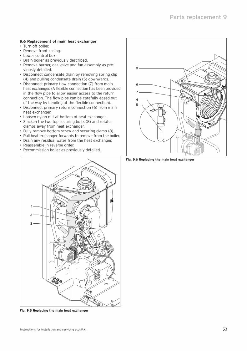
53
Parts replacement 9
Instructions for installation and servicing ecoMAX 53
9.6 Replacement of main heat exchanger• Turn off boiler.• Remove front casing.• Lower control box.• Drain boiler as previously described.• Remove burner, gas valve and fan assembly as pre-
viously detailed.• Disconnect condensate drain by removing spring clip
(4) and pulling condensate drain (5) downwards.• Disconnect primary flow connection (7) from main
heat exchanger. (A flexible connection has been providedin the flow pipe to allow easier access to the returnconnection. The flow pipe can be carefully eased outof the way by bending at the flexible connection).
• Disconnect primary return connection (6) from mainheat exchanger.
• Loosen nylon nut at bottom of heat exchanger.• Slacken the two top securing bolts (8) and rotate
clamps away from heat exchanger.• Fully remove bottom screw and securing clamp (8).• Pull heat exchanger forwards to remove from the boiler.• Drain any residual water from the heat exchanger.• Reassemble in reverse order.• Recommission boiler as previously detailed.
Fig. 9.5 Replacing the main heat exchanger
Fig. 9.6 Replacing the main heat exchanger
8
6
7
4
5
1
2
3
83 41 77_12 GB04.04.qxd 22.09.2004 12:34 Uhr Seite 53
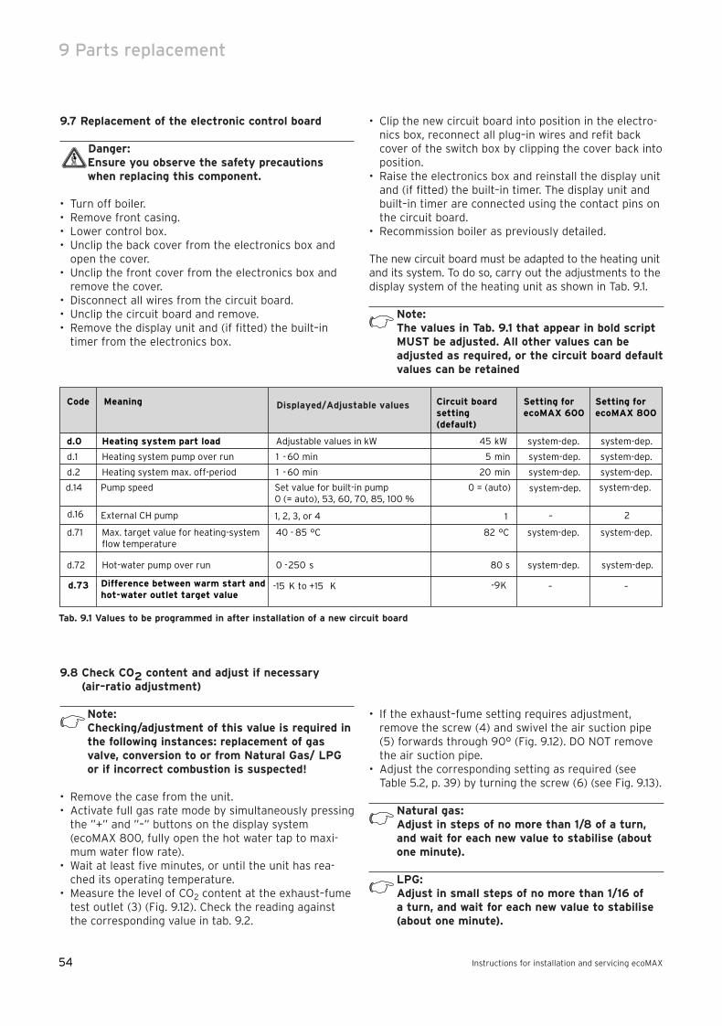
54
9 Parts replacement
Instructions for installation and servicing ecoMAX54
9.7 Replacement of the electronic control board
Danger:Ensure you observe the safety precautionswhen replacing this component.
• Turn off boiler.• Remove front casing.• Lower control box.• Unclip the back cover from the electronics box and
open the cover.• Unclip the front cover from the electronics box and
remove the cover.• Disconnect all wires from the circuit board.• Unclip the circuit board and remove.• Remove the display unit and (if fitted) the built–in
timer from the electronics box.
• Clip the new circuit board into position in the electro-nics box, reconnect all plug–in wires and refit backcover of the switch box by clipping the cover back intoposition.
• Raise the electronics box and reinstall the display unitand (if fitted) the built–in timer. The display unit andbuilt–in timer are connected using the contact pins onthe circuit board.
• Recommission boiler as previously detailed.
The new circuit board must be adapted to the heating unitand its system. To do so, carry out the adjustments to thedisplay system of the heating unit as shown in Tab. 9.1.
Note: The values in Tab. 9.1 that appear in bold scriptMUST be adjusted. All other values can be adjusted as required, or the circuit board defaultvalues can be retained
9.8 Check CO2 content and adjust if necessary (air–ratio adjustment)
Note:Checking/adjustment of this value is required inthe following instances: replacement of gasvalve, conversion to or from Natural Gas/ LPGor if incorrect combustion is suspected!
• Remove the case from the unit.• Activate full gas rate mode by simultaneously pressing
the ”+” and ”–” buttons on the display system(ecoMAX 800, fully open the hot water tap to maxi-mum water flow rate).
• Wait at least five minutes, or until the unit has rea-ched its operating temperature.
• Measure the level of CO2 content at the exhaust–fumetest outlet (3) (Fig. 9.12). Check the reading againstthe corresponding value in tab. 9.2.
• If the exhaust–fume setting requires adjustment, remove the screw (4) and swivel the air suction pipe(5) forwards through 90° (Fig. 9.12). DO NOT removethe air suction pipe.
• Adjust the corresponding setting as required (seeTable 5.2, p. 39) by turning the screw (6) (see Fig. 9.13).
Natural gas:Adjust in steps of no more than 1/8 of a turn,and wait for each new value to stabilise (aboutone minute).
LPG:Adjust in small steps of no more than 1/16 of a turn, and wait for each new value to stabilise(about one minute).
Tab. 9.1 Values to be programmed in after installation of a new circuit board
Code Meaning Circuit board Setting forecoMAX 600
Setting forecoMAX 800setting
(default)
d.0 Heating system part load Adjustable values in kW 45 kW system-dep. system-dep.
d.1 Heating system pump over run 1 - 60 min 5 min system-dep. system-dep.
d.2 Heating system max. off-period 1 - 60 min 20 min system-dep. system-dep.
d.71 Max. target value for heating-systemflow temperature
40 - 85 °C 82 °C system-dep. system-dep.
d.72 Hot-water pump over run 0 -250 s 80 s system-dep. system-dep.
d.73 -15 K to +15 K -9 KDifference between warm start andhot-water outlet target value
Displayed/Adjustable values
– –
d.14 Pump speed Set value for built-in pump0 (= auto), 53, 60, 70, 85, 100 %
0 = (auto) system-dep.system-dep.
d.16 External CH pump 1, 2, 3, or 4 1 – 2
83 41 77_12 GB04.04.qxd 22.09.2004 12:34 Uhr Seite 54
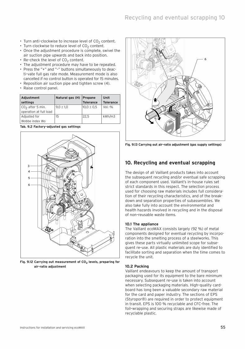
55Instructions for installation and servicing ecoMAX 55
• Turn anti–clockwise to increase level of CO2 content.• Turn clockwise to reduce level of CO2 content.• Once the adjustment procedure is complete, swivel the
air suction pipe upwards and back into position.• Re–check the level of CO2 content.• The adjustment procedure may have to be repeated.• Press the ”+” and ”–” buttons simultaneously to deac-
ti–vate full gas rate mode. Measurement mode is alsocancelled if no control button is operated for 15 minutes.
• Reposition air suction pipe and tighten screw (4).• Raise control panel.
Adjustment Natural gas (H) Propane Unit
settings Tolerance Tolerance
CO2 after 5 min. 9,0 ± 1,0 10,0 ± 0,5 Vol.–%
operation at full load
Adjusted for 15 22,5 kWh/m3
Wobbe index Wo
Tab. 9.2 Factory–adjusted gas settings
Fig. 9.12 Carrying out measurement of CO2 levels, preparing for
air–ratio adjustment
Fig. 9.13 Carrying out air–ratio adjustment (gas supply settings)
10. Recycling and eventual scrapping
The design of all Vaillant products takes into accountthe subsequent recycling and/or eventual safe scrappingof each component used. Vaillant’s in–house rules setstrict standards in this respect. The selection processused for choosing raw materials includes full considera-tion of their recycling characteristics, and of the break-down and separation properties of subassemblies. Wealso take fully into account the environmental andhealth hazards involved in recycling and in the disposalof non–reusable waste items.
10.1 The applianceThe Vaillant ecoMAX consists largely (92 %) of metalcomponents designed for eventual recycling by incorpo-ration into the smelting process of a steelworks. Thisgives these parts virtually unlimited scope for subse-quent re–use. All plastic materials are duly identified tofacilitate sorting and separation when the time comes torecycle the unit.
10.2 PackingVaillant endeavours to keep the amount of transportpackaging used for its equipment to the bare minimumnecessary. Subsequent re–use is taken into accountwhen selecting packaging materials. High–quality card-board has long been a valuable secondary raw materialfor the card and paper industry. The sections of EPS(Styropor®) are required in order to protect equipmentin transit. EPS is 100 % recyclable and CFC–free. Thefoil–wrapping and securing straps are likewise made ofrecyclable plastic.
6
3
4
5
6
Recycling and eventual scrapping 10
83 41 77_12 GB04.04.qxd 22.09.2004 12:34 Uhr Seite 55

83
41
77
_12
GB
10 2
00
4S
ub
ject
to
alt
erat
ion
83 41 77_12 GB04.04.qxd 22.09.2004 12:34 Uhr Seite 56