Embed Size (px)
Citation preview

A, B, C - functions which are available in modules, respectively: A, B, C
SERVICE AND ASSEMBLY MANUAL ISSUE: v1.1
APPLICABLE TO SOFTWARE:
MODULE A MODULE B PANEL
v04.30.** v04.30.** v04.**.**
Boiler regulator
ecoMAX810P3-L TOUCH
FOR PELLET BOILERS
09-06-2014

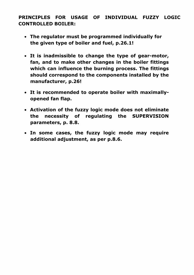
PRINCIPLES FOR USAGE OF INDIVIDUAL FUZZY LOGIC
CONTROLLED BOILER:
The regulator must be programmed individually for
the given type of boiler and fuel, p.26.1!
It is inadmissible to change the type of gear-motor,
fan, and to make other changes in the boiler fittings
which can influence the burning process. The fittings
should correspond to the components installed by the
manufacturer, p.26!
It is recommended to operate boiler with maximally-
opened fan flap.
Activation of the fuzzy logic mode does not eliminate
the necessity of regulating the SUPERVISION
parameters, p. 8.8.
In some cases, the fuzzy logic mode may require
additional adjustment, as per p.8.6.

TABLE OF CONTENTS1 RECOMMENDATIONS REGARDING
SAFETY .................................................. 6
2 GENERAL INFORMATION .................. 7
3 INFORMATION ABOUT
DOCUMENTATION .................................... 7
4 STORAGE OF DOCUMENTATION ........ 7
5 APPLIED SYMBOLS .......................... 7
6 DIRECTIVE WEEE 2002/96/EG .......... 7
7 STRUCTURE – MAIN MENU ............... 9
8 OPERATING THE REGULATOR .......... 10 8.1 DESCRIPTION OF DISPLAY MAIN WINDOW ............... 10
8.2 SWITCHING ON AND OFF THE BOILER ...................... 10
8.3 SETTING PRESET BOILER TEMPERATURE ................... 11
8.4 FIRING-UP ..................................................... 11
8.5 OPERATION MODE ........................................ 11
8.6 OPERATION IN I.FUZZYLOGIC MODE ................... 12
8.7 OPERATION IN THE STANDARD MODE ..................... 13
8.8 SUPERVISION MODE ....................................... 13
8.9 BURNING OFF ................................................ 14
8.10 STANDSTILL ................................................... 14
8.11 DOMESTIC HOW WATER SETTINGS DHW ................ 14
8.12 SETTING PRESET DHW TEMPERATURE ................... 14
8.13 DHW TANK HYSTERESIS ...................................... 14
8.14 ENABLING THE SUMMER FUNCTION .................... 14
8.15 DHW TANK DISINFECTION ................................... 15
8.16 MIXER CIRCUITS SETTINGS ................................... 15
8.17 WEATHER CONTROLLED OPERATION ...................... 16
8.18 DESCRIPTION OF SETTINGS FOR NIGHT-TIME DECREASES
17
8.19 CIRCULATING PUMP CONTROL .............................. 18
8.20 FUEL LEVEL SETUP .............................................. 18
8.21 OPERATION WITH ADDITIONAL FEEDER ................... 18
8.22 INFORMATION ................................................... 19
8.23 MANUAL CONTROL ............................................ 19
8.24 OPERATION IN ACCORDANCE WITH THE SCHEDULE .... 19
8.25 FAVOURITE MENU .............................................. 19
9 SERVICE - MENU STRUCTURE .......... 21
10 HYDRAULIC DIAGRAMS ................... 22 10.1 SCHEMA 1 ........................................................ 22
10.2 SCHEMA 2 ........................................................ 23
11 TECHNICAL DATA ........................... 24
12 CONDITIONS OF STORAGE AND
TRANSPORT ........................................... 24
13 MOUNTING REQUIREMENTS ............ 24 13.1 ENVIRONMENTAL CONDITIONS ............................. 24
13.2 INSTALLATION REQUIREMENTS .............................. 24
13.3 ASSEMBLY OF CONTROL PANEL ............................. 24
13.4 DISASSEMBLY OF CONTROL PANEL ......................... 25
13.5 MOUNTING OF WORKING MODULE ........................ 25
13.6 IP RATING ........................................................ 26
13.7 ELECTRIC CONNECTION ........................................ 26
13.8 PROTECTIVE CONNECTION ................................... 27
13.9 CONNECTION OF TEMPERATURE SENSORS ................ 30
13.10 CONNECTION OF WEATHER SENSOR .................... 30
13.11 TESTING OF TEMPERATURE SENSORS .................. 30
13.12 CONNECTION OF MIXERS ROOM THERMOSTAT ...... 31
13.13 CONNECTION OF RESERVE BOILER ...................... 31
13.14 CONNECTION OF ALARM ANNOUNCING ............... 32
13.15 CONNECTION OF MIXER ................................... 33
13.16 CONNECTION OF CIRCULATING PUMP ................. 33
13.17 CONNECTION OF STB TEMPERATURE LIMITER ...... 34
13.18 CONNECTION OF ROOM CONTROL PANEL ............. 34
14 BOILER SERVICE SETTINGS ........... 35 14.1 FIRING-UP ......................................................... 35
14.2 BURINING-OFF ................................................... 35
14.3 SUPERVISION TIME .............................................. 35
14.4 FEED. TIME SUPERV. ......................................... 35
14.5 FEEDER INTERCAL SUPERV. ................................. 35
14.6 AIRFLOW OPER. EXTEND. IN SUPERVISION MODE .. 35
14.7 THERMOSTAT SELECTION...................................... 36
14.8 MIN. PRESET BOILER TEMPERATURE ....................... 36
14.9 MAX. PRE-SET BOILER TEMPERATURE ..................... 36
14.10 MIN. BLOW-IN OUTPUT ................................... 36
14.11 NO FUEL DETECTION TIME ................................ 36
14.12 MAXIMUM FEEDER TEMPERATURE ..................... 36
14.13 POKER CYCLE TIME .......................................... 36
14.14 RESERVE BOILER ............................................. 37
14.15 BOILER COOLING TEMP. ................................... 37
14.16 A, B, C PARAMETERS OF INDIVIDUAL FUZZY LOGIC 37
15 CH AND CUW SERVICE SETTINGS ... 37 15.1 CH PUMP ACTIVATION TEMPERATURE .................... 37
15.2 CH PUMP STANDSTILL AT HUW LOADING ............... 37
15.3 MIN HUW TEMPERATURE ................................... 37
15.4 MAX HUW TEMPERATURE .................................. 37
15.5 INCREASE OF BOILER TEMPERATURE BY HUW, MIXER
CIRCUIT AND BUFFER STATUS ............................................ 38
15.6 HUW OPERATIONS EXT. ...................................... 38
15.7 HEAT EXCHANGER ............................................... 38
16 MIXER SERVICE SETTINGS ............. 38 16.1 MIXER SUPPORT ............................................ 38
16.2 THERMOSTAT SELECTION...................................... 39
16.3 MIN. PRESET MIXER TEMPERATURE ........................ 39
16.4 MAX. PRESET MIXER TEMPERATURE ....................... 39
16.5 PROPORTIONAL RANGE ........................................ 39
16.6 INTEGR. TIME CONST. .......................................... 39
16.7 VALVE OPENING TIME .......................................... 39
16.8 PUMP OFF BY THERMOSTAT ................................. 39
17 SHOW ADVANCED SETUP ............... 39
18 SERVICE COUNTERS ...................... 39
19 RESTORE FACTORY SETTINGS ........ 40
20 FAN ROTATION DETECTION ............ 40
21 LAMBDA SENSOR .......................... 40
22 ALARM DESCRIPTION .................... 40 22.1 EXHAUST TEMPERATURE SENSOR DAMAGE .............. 40

5
22.2 EXCESS OF MAX. BOILER TEMPERATURE .................. 41
22.3 EXCESS OF MAX. FEEDER TEMPERATURE .................. 41
22.4 BOILER TEMPERATURE SENSOR DAMAGE ................. 41
22.5 FEEDER TEMPERATURE SENSOR DAMAGE ................ 41
22.6 NO COMMUNICATION ......................................... 42
22.7 UNSUCCESSFUL BOILER FIRING-UP ATTEMPT ............ 42
22.8 UNSUCCESSFUL ATTEMPT OF CONTAINER LOADING ... 42
22.9 FAN DAMAGE .................................................... 42
23 OTHERS ........................................ 42 23.1 POWER FAILTURE ............................................... 42
23.2 ANTI-FREEZING PROTECTION ................................ 42
23.3 PROTECTION OF PUMPS AGAINST CLOGGING ............ 42
24 REPLACEMENT OF PARTS AND
COMPONENTS ........................................ 42 24.1 REPLACEMENT OF MAINS FUSE ............................. 42
24.2 REPLACEMENT OF CONTROL PANEL ........................ 43
24.3 REPLACEMENT OF WORKING MODULE .................... 43
24.4 SOFTWARE UP-GRADE ......................................... 43
25 TROUBLESHOOTING ....................... 44
26 REGULATOR SETUP BY BOILER
MANUFACTURER. .................................... 45 26.1 ACTIVATING INDIVIDUAL FUZZY LOGIC AND CHANGING
BOILER TYPE .................................................................. 45
6
1 RECOMMENDATIONS REGARDING
SAFETY
Requirements concerning safety are
described in detail in individual
chapters of this manual. Apart from
them, the following requirements
should in particular be observed.
Before starting assembly,
repairs or maintenance, as well
as during any connection
works, please make sure that
the mains power supply is
disconnected and that terminals
and electric wires are devoid of
voltage.
After the regulator is turned off
using the keyboard, dangerous
voltage still can occur on its
terminals.
The regulator cannot be used at
variance with its purpose.
Additional automatics which
protect the boiler, central
heating (CH) system, and
domestic hot water system
against results of malfunction of
the regulator, or of errors in its
software, should be applied.
Choose the value of the
programmed parameters
accordingly to the given type of
boiler and fuel, taking into
consideration all the operational
conditions of the system.
Incorrect selection of the
parameters can cause
malfunction of the boiler (e.g.
overheating of the boiler, the
flame going back to the fuel
feeder, etc.),
The regulator is intended for
boiler manufacturers. Before
applying the regulator, a boiler
manufacturer should check if
the regulator’s mating with the
given boiler type is proper, and
whether it can cause danger.
The regulator is not an
intrinsically safe device, which
means that in the case of
malfunction it can be the source
of a spark or high temperature,
which in the presence of
flammable dusts or liquids can
cause fire or explosion. Thus,
the regulator should be
separated from flammable
dusts and gases, e.g. by means
of an appropriate body.
The regulator must be installed
by a boiler manufacturer in
accordance with the applicable
safety standards.
The programmed parameters
should only be altered by a
person familiarized with this
manual.
The device should only be used
in heating systems in
accordance with the applicable
regulations.
The electric system in which the
regulator operates must be
protected by means of a fuse,
selected appropriately to the
applied loads.
The regulator cannot be used if
its casing is damaged.
In no circumstances can the
design of the regulator be
modified.
Electronic isolation of the
connected devices is applied in
this regulator.
The regulator consists of two
subassemblies. In the case of
replacing one subassembly,
make sure to maintain
compatibility with the other
one. More information on that
issue can be found in the
documentation intended for
fitters.
Keep the regulator out of reach
of children.

7
2 General information
Boiler regulator ecoMAX 810 model P3
version L, is a modern electronic device
intended to control pellet boiler operation.
The regulator is a multipurpose device:
it automatically maintains a preset boiler
temperature by controlling the fuel
combustion process,
it controls timing of feeding screw and
fan,
it automatically stabilizes a preset
temperature of the domestic hot water
tank,
it automatically maintains preset
temperature of several independent
mixer heating cycles.
The preset temperature of heating cycles and
boiler can be set on the basis of a weather
sensor readouts.
The regulator features an Individual Fuzzy
Logic function. It allows to optimize the
combustion process, which is in favour of
natural preservation, decreases fuel
consumption and relieves the user of the
necessity of adjusting the burner
parameters.
Possibility of cooperation with room
thermostats, separate for each heating
cycles, facilitates maintaining comfortable
temperature in the heated rooms. Moreover,
if need arises, the device enables a reserve
boiler (gas- or oil-fired).
The device has modular construction,
consisting of control panel, main boiler
control module (A), and module controlling
mixer cycles and DHW (B).
The device is operated in an easy and
intuitive way.
Regulator can cooperate with an additional
control panel situated in living quarters. It
can be used in a household and similar
facilities, as well as in light industrialized
facilities.
3 Information about documentation
The regulator manual is a supplement for the
boiler manual. In particular, except for this
manual, the boiler manual should also be
observed. The regulator manual is divided
into two parts: for user and fitter. Yet, both
parts contain important information,
significant for safety issues, hence the user
should read both parts of the manual.
We are not responsible for any damages
caused by failure to observe these
instructions.
4 Storage of documentation
This assembly and operation manual, as well
as any other applicable documentation,
should be stored diligently, so that it was
available at any time. In the case of removal
or sale of the device, the attached
documentation should be handed over to the
new user / owner.
5 Applied symbols
In this manual the following graphic symbols
are used:
- useful information and tips,
- important information, failure to
observe these can cause damage of
property, threat for human and
household animal health and life.
Caution: the symbols indicate important
information, in order to make the manual
more lucid. Yet, this does not exempt the
user from the obligation to comply with
requirements which are not marked with a
graphic symbol.
6 Directive WEEE 2002/96/EG
Act on electrical and electronic
equipment
Recycle the product and the
packaging at the end of the
operational use period in an
appropriate manner
Do not dispose of the product
together with normal waste.
Do not burn the product.

8
REGULATOR INSTRUCTION MANUAL
ecoMAX810P3-L TOUCH
9
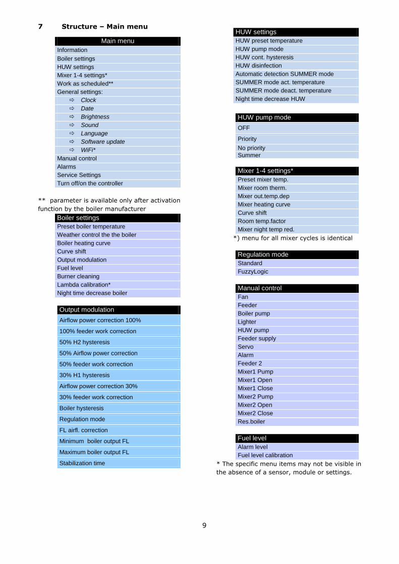
7 Structure – Main menu
** parameter is available only after activation
function by the boiler manufacturer
Boiler settings
Preset boiler temperature
Weather control the the boiler
Boiler heating curve
Curve shift
Output modulation
Fuel level
Burner cleaning
Lambda calibration*
Night time decrease boiler
Output modulation
Airflow power correction 100%
100% feeder work correction
50% H2 hysteresis
50% Airflow power correction
50% feeder work correction
30% H1 hysteresis
Airflow power correction 30%
30% feeder work correction
Boiler hysteresis
Regulation mode
FL airfl. correction
Minimum boiler output FL
Maximum boiler output FL
Stabilization time
HUW settings
HUW preset temperature
HUW pump mode
HUW cont. hysteresis
HUW disinfection
Automatic detection SUMMER mode
SUMMER mode act. temperature
SUMMER mode deact. temperature
Night time decrease HUW
HUW pump mode
OFF
Priority
No priority
Summer
Mixer 1-4 settings*
Preset mixer temp.
Mixer room therm.
Mixer out.temp.dep
Mixer heating curve
Curve shift
Room temp.factor
Mixer night temp red.
*) menu for all mixer cycles is identical
Regulation mode
Standard
FuzzyLogic
Manual control
Fan
Feeder
Boiler pump
Lighter
HUW pump
Feeder supply
Servo
Alarm
Feeder 2
Mixer1 Pump
Mixer1 Open
Mixer1 Close
Mixer2 Pump
Mixer2 Open
Mixer2 Close
Res.boiler
Fuel level
Alarm level
Fuel level calibration
* The specific menu items may not be visible in
the absence of a sensor, module or settings.
Main menu
Information
Boiler settings
HUW settings
Mixer 1-4 settings*
Work as scheduled**
General settings:
Clock
Date
Brightness
Sound
Language
Software update
WiFi*
Manual control
Alarms
Service Settings
Turn off/on the controller

10
8 Operating the regulator
This section briefly describes how the
regulator should be operated.
8.1 Description of display main
window
Fig. 1 Display main window
Legend:
1. Mode of regulator operation: FIRING-UP,
OPERATION, SUPERVISION, BURNING
OFF, R.P.OUT, STANDSTILL,
2. preset boiler temperature,
3. measured boiler temperature,
4. key to enter ’’Menu” list
5. Information fields:
fan,
feeder 1,
feeder 2 (additional),
pump,
lighter,
poker .
6. measured temperature of HUW container,
7. preset temperature of HUW container,
8. clock time and weekday
9. outside temperature (weather),
10. field of functions, which modify preset
boiler temperature -meaning of the symbols:
- opening of room thermostat contacts
– preset room temperature has been
reached;
- of preset boiler temperature for
active time intervals;
- increase of preset boiler temperature
for the time of HUW container filling;
- increase of preset boiler temperature
by mixer circuit;
- increase of preset temperature for
buffer loading.
Both, left and right windows may display
different information. By touching the screen,
you may navigate between displayed
information: mixer circuits (1, 2, 3, 4, 5),
information window, HUW window, fuel level
window.
To have the fuel level displayed, first enter
the settings acc. sec. 8.20. Note: fuel level
may be displayed on ecoSTER-TOUCH room
control panel.
8.2 Switching on and off the boiler
Make sure fuel is present in the tank and
tank hatch is closed. Now boiler may be
switched on. To start the boiler - press
BURNER OFF? at any place on the screen.
The message: ACTIVE REGULATOR?
appears.
Fig. 2 Main window
Confirm the message. Boiler enters firing-up
stage. There is also another method of boiler
start-up. Press MENU button and find and
press button in pie menu.
To stop the boiler - press MENU button, and
find and press button in pie menu.
Note: regulator enters burning off phase.
Upon completion of burning off stage, the
message BURNER OFF appears.

11
8.3 Setting preset boiler temperature
Preset boiler temperature, just like the
preset mixer circuit temperature, can be set
in the menu (possible settings of these
temperatures are limited by the scope of
their corresponding regulator service
parameters).
Boiler settings > Preset boiler temp.
Mixer 1 settings > Preset mixer temp.
Mixer 2 settings > Preset mixer temp.
Mixer 3 settings > Preset mixer temp.
Mixer 4 settings > Preset mixer temp.
The value set as Preset boiler temp. is
ignored by the regulator if the preset boiler
temperature is controlled by weather sensor.
Regardless of that, the preset boiler
temperature is automatically increased in
order to fill the hot utility water tank and
feed heating mixer cycles.
8.4 FIRING-UP
FIRING-UP mode is used to automatic firing
up of boiler furnace. Total time of firing-up
depends on the regulator settings (feeder
operation time, heater operation time, etc.)
and on the boiler conditions before firing up.
All parameters, which affect firing-up process
are grouped in the menu:
SERVICE SETTINGS >BOILER SETTINGS
Detailed description of firing-up cycle:
Fan turns on with the power set in the
parameter of Blowing power- firing up,
Small dose of fuel (approx.20% basic dose)
is supplied,
Conditions of the furnace are checked – i.e.
once the exhaust temperature has reached
the value of Ex. temp. at the end of firing-
up or has increased by Ex.temp.delta
within the time set in the parameter
Ignition test time elapsed from the fan
start, firing-up process stops. It means
firing-up has been detected and regulator
enters OPERATION mode. In case the
criteria of furnace firing-up have not been
fulfilled, regulator attempts to clean the
furnace and fire it up:
poker is activated to operate over Poker
cycle time ,
fuel is supplied over Feeding time,
fan turns on with the power set in the
parameter of Blowing power- firing up,
lighter switches on for Firing-up time. The
regulator checks within this time whether
fuel in the burner has been kindled. Fuel is
deemed kindled once the temperature
increment indicated on exhaust
temperature sensor has reached the value
of Ex.temp.delta or the exhaust
temperature has increased above the value
set in Ex. temp. at the end of firing-up. If
firing-up has been successfully completed,
lighter turns off and regulator enters
OPERATION mode,
Just upon entry the OPERATION mode,
regulator checks whether the exhaust
temperature has increased by the value of
Ex.temp.delta 2. If NOT- regulator returns
to firing-up mode. If YES- it remains in
OPERATION mode.
In case the firing up has not been
successfully completed, further attempts to
fire-up the furnace are carried out with fuel
dose (Feeding time) reduced to 10% of the
dose used in first attempt.
Upon execution of three unsuccessful
attempts, the alarm of Unsuccessful boiler
firing-up attempt is produced. Boiler
operation is interrupted and cannot be
automatically resumed - operator's
intervention is required. Once the causes of
firing-up failure have been removed, re-start
the boiler.
8.5 OPERATION MODE
In this mode the boiler runs automatically
according Individual Fuzzy Logic or
STANDARD algorithm. Fan operates
continuously, which is shown on Fig. 3. Fuel
feeder switches on periodically
Fig. 3 Fan and feeder operation cycles.
The operation cycle is composed of feeder
operation time (feeding time) and feeder
standstill time (feeder interval). Power of the
fan and the feeding time are determined by
either regulation algorithm described below.

12
If a HUW container needs to be filled in
OPERATION mode at pre-set boiler
temperature, which is lower than the value
required to its filling, the regulator will
automatically increase preset boiler
temperature for the time of HUW container
filling
8.6 OPERATION in I.FuzzyLogic mode
This mode may be activated in the menu:
Regulation mode
Using the function of IndividualFuzzyLogic,
settings of which are individually adapted to
the given boiler allows obtaining optimum
combustion process, which is more
environment friendly, supports fuel savings
and in most instances eliminates the need to
adjust regulator parameters.
During operation with use of
Individual Fuzzy Logic algorithm, parameters
of feeder operation (Feeding Time, Feeder
Interval) and blow-in output needn't be set-
up. Three-stage output modulation is inactive
– the regulator automatically sets feeder and
fan control parameters in a stepless manner.
In Individual Fuzzy Logic mode, the regulator
strives to eliminate the need to bring the
boiler into SUPERVISION mode, and to
produce exactly as much heat as CH system
requires. Change-over to SUPERVISION
mode occurs once the actual boiler
temperature has exceeded the preset value
by 5 °C.
Please note Individual Fuzzy Logic algorithm
is adapted individually to the given boiler and
fuel type and may work properly only with
this boiler and fuel. Therefore
IndividualFuzzyLogic mode has to be
activated by the boiler manufacturer in
accordance with sec 26.1. In case this mode
has not been activated, when attempting to
change the mode, a prompt ’FUNCTION NOT
AVALAIBLE’ appears.
Change of settings of Individual
Fuzzy Logic algorithm.
Sometimes, depending on the fuel quality,
air flow has to be adjusted in
IndividualFuzzyLogic mode.
The user may change the settings as follows:
BOILER SETTINGS > Output Modulation
> FL airfl. correction
BOILER SETTINGS > Output Modulation
> Min.boil.output FL
BOILER SETTINGS > Output Modulation
> Max. boil.output FL
The range of setting correction has been
deliberately limited. Change of FL airfl.
correction setting is not recommended if
combustion process runs properly i.e. no
incompletely burnt fuel particles are
present. In case of poor fuel quality, when
presence of incompletely burnt fuel particles
is obvious, amount of supplied air may be
increased. If the fuel is very dry, causing
high combustion rate and too intensive
furnace burning-out, the value of FL airfl.
correction may be reduced.
In Individual Fuzzy Logic regulation
mode, the values of parameters
related to blow-in output and
feeder operation and standstill
times available in menu: BOILER
SETTINGS > Output Modulation
are not used by regulator operation
algorithm. These settings are used
only in STANDARD mode.
When using IndividualFuzzyLogic
control, fan baffle should be fully
opened, and the boiler has to be
clean. In case of required fan or
feeder replacement - use identical
types of both pieces of equipment.
Once the actual boiler temperature has
exceeded the preset value by 5⁰C, the
regulator automatically enters SUPERVISION
mode.

13
8.7 Operation in the standard mode
ecoMAX810 TOUCH P-L boiler regulator is
equipped with boiler output modulation
function enabling gradual reduction of boiler
output when approaching the preset boiler
temperature. In this mode of regulation, the
regulator uses output modulation algorithm.
Levels of boiler output are available in menu:
BOILER SETTINGS > Output Modulation
Each of the levels (100%, 50% or 30%) may
be assigned individual values of fuel feeding
time and blow-in output, which determine
actual boiler output. Values of hysteresis (H1
and H2) determine when the boiler should
work with selected output level. Each of
these values is referred to the measured
boiler temperature vs. its preset value. H1
and H2 values may be so set-up that the
modulation will follow without intermediate
level i.e. the boiler output will change
directly from 100% to 30%.
Fig. 4 Output modulation hystereses H1 and H2.
Once the actual boiler temperature has
reached the preset value, the regulator
enters SUPERVISION mode
8.8 SUPERVISION mode
The SUPERVISION mode occurs both during
operation with STANDARD, as well as with
Individual Fuzzy Logic control algorithm.
The regulator switches into the
SUPERVISION automatically, without the
user’s intervention:
- in the case of Standard control mode -
upon reaching preset boiler temperature,
- during Individual Fuzzy Logic control - upon
exceeding the preset boiler temperature by
5°C. In the Individual Fuzzy Logic mode, the
regulator strives to avoid switching the boiler
into the SUPERVISION mode, and to supply
as much heat, as the CH system requires at
the time.
In the SUPERVISION mode, the regulator
supervises the furnace, so that it would not
go out. For this purpose, the airflow and the
feeder are activated only for a while, rarer
than in the OPERATION mode. Without
causing further temperature increase.
The airflow does not work continuously,
it is activated cyclically together with
the fuel feeder, which prevents the
flame from going out during boiler
standstill.
All parameters regarding boiler setup in the
SUPERVISION can be found in the menu :
Service settings > Boiler settings >
Supervision
Parameters of the SUPERVISION mode
should be set in accordance with boiler
manufacturer’s recommendations. They
should be chosen in such a way, that the
furnace did not go out during boiler standstill
(at the same time, it should not fire up too
intensively, as this will trigger increase in the
boiler temperature). Duration of the feeder
operation and interval in the SUPERVISION
mode are set using parameters:
... > SUPERVISION > Feeding time
... > SUPERVISION > Feeder interval
Airflow extension time necessary to fire-up
supplied fuel is set in:
... > SUPERVISION >Airflow
oper.extend.

14
Parameters should be selected in
such a way, that boiler
temperature would gradually
decrease when this mode is active.
Improper settings can cause the
boiler to overheat
Airflow in the SUPERVISION mode
operates with power set in the power
modulation parameter 30% Airflow
power.
The regulator returns to the OPERATION
mode automatically after boiler temperature
decreases by the value of boiler hysteresis in
relation to the preset temperature.
Maximum boiler operation time in the
supervision mode is defined by parameter:
... > Supervision > Supervision time
If after lapse of this time from the moment
of the regulator’s entering the supervision
mode, there is no need to reactivate the
boiler, the regulator will commence the
process of putting the boiler out.
8.9 BURNING OFF
In BURNING OFF mode, rest of pellets is
burnt and boiler is being prepared to stop or
shut-down.
All parameters, which affect burning-off
process are grouped in the menu:
SERVICE SETTINGS > BOILER SETTINGS
> BURNING OFF
Detailed description of burning-off cycle:
Fuel feeder stops,
Remaining fuel is burnt – the fan turns on
for the time set in Burning-off time with the
power set in the parameter of Air flush
intensity,
The furnace is cleaned - poker switches on.
Upon automatic burning-off, regulator enters
STANDSTILL mode.
8.10 STANDSTILL
In the STANDSTILL mode, the boiler is put
out and awaits signal to resume heating.
A signal to start heating can be:
decrease in preset boiler temperature
below the preset temperature minus the
value of boiler hysteresis (Boiler
hysteresis),
if the boiler is set to work with a buffer -
decrease in upper buffer temperature
below the preset value (Loading start
temperature).
8.11 Domestic how water settings
DHW
The device controls temperature of the
domestic how water - DHW – tank, provided
that a DHW temperature sensor is
connected. If the sensor is disconnected, an
information about lack thereof is displayed in
the main window. The parameter:
HUW settings > HUW pump mode allows
the user to:
disable filling of the tank, parameter
off,
set DHW priority, using the priority
parameter - in this case, the CH pump
is deactivated to speed up filling of
the DHW tank.
set simultaneous operation of the CH
and DHW pump, using parameter no
priority,
enable the summer function.
8.12 Setting preset DHW temperature
Preset DHW temperature is defined by
parameter:
DHW settings > Preset DHW temp.
8.13 DHW tank hysteresis
Below temperature DHW preset temp.
reduced by DHW tank hysteresis, the DHW
pump is activated in order to fill the DHW
tank.
When value of hysteresis is set too
low, the DHW pump will start faster
after decrease in DHW temperature.
8.14 Enabling the SUMMER function
In order to activate the SUMMER function,
which enables to load the DHW tank in the
summer, without the need for activating the
CH system and mixer cycles, set the
parameter DHW pump operation mode to
summer.

15
The SUMMER function cannot be
enabled if the DHW sensor is
disconnected.
Do not enable the summer
function if the DHW pump is
disconnected or damaged.
The SUMMER function can be enabled
automatically, on the basis of readouts from
the weather sensor. This functionality is
enabled with the following parameters:
DHW settings > Auto SUMMER detect.
DHW settings > Activ.temp.SUMMER
DHW settings > Deactiv.temp.SUMMER
8.15 DHW tank disinfection
The regulator has a function of automatic,
periodic heating of the DHW tank to
temperature of 70 °C. The purpose is to
remove bacterial flora from the DHW tank.
The household members must
definitely be informed about the fact
of activating disinfection, as there is
a hazard of scalding with hot utility
water.
Once a week on Sunday night, at 02:00, the
regulator increases the DHW tank
temperature. After 10 minutes of keeping the
tank at 70 °C, the DHW pump is deactivated
and the boiler resumes normal operation. Do
not enable the disinfection function if DHW
support is deactivated.
8.16 Mixer circuits settings
Settings for the first mixer circuit can be
found in the menu:
Mixer 1 settings
Settings for other mixers can be accessed in
next menu items and they are identical for
each circuit.
Settings for mixer without weather sensor
It is necessary to manually set the required
water temperature in the heating mixer
circuit using parameter Preset mixer temp.,
e.g. at a value of 50°C. The value should
allow to obtain the required room
temperature.
After connecting room thermostat, it is
necessary to set a value of decrease in
preset mixer temperature by thermostat
(parameters Mixer room therm.) e.g. at 5°C.
This value should be selected by trial and
error. The room thermostat can be a
traditional thermostat (no/nc), or room panel
ecoSTER200. Upon activation of the
thermostat, the preset mixer circuit
temperature will be decreased, which, if
proper decrease value is selected, will stop
growth of temperature in the heated room.
Settings for mixer with weather sensor
(without room thermostat ecoSTER200)
Set parameter Weather contr.mixer to on.
Select weather curve as per point 8.17
Using parameter Curve translation, set
preset room temperature following the
formula:
Preset room temperature = 20°C + heating
curve translation.
Example.
To obtain room temperature of 25°C, value
of the heating curve translation must be set
at 5°C. To obtain room temperature of 18°C,
value of the heating curve translation must
be set at -2°C.
In this setup, it is possible to connect a room
thermostat which will equalize the inaccuracy
of selecting heating curve, if the selected
heating curve value is too high. In such case,
it is necessary to set the value of preset
mixer temperature decrease by thermostat,
e.g. at 2°C. After opening of the thermostat
contacts, the preset mixer circuit
temperature will be decreased, which, if
proper decrease value is selected, will stop
growth of temperature in the heated room.
Settings for mixer with weather sensor and
with room thermostat ecoSTER200)
Set parameter Weather contr.mixer to on.
Select weather curve as per point 8.17
The ecoSTER200 regulator automatically
translates the heating curve, depending on
the preset room temperature.

16
The regulator relates the setting to 20 °C,
e.g. for preset room temperature = 22 °C,
the regulator will translate the heating curve
by 2°C, for preset room temperature =
18 °C, the regulator will translate the heating
curve by
-2 °C. In some cases described in point 8.17,
it may be necessary to fine-tune the heating
curve translation.
In this setup, the ecoSTER200 room
thermostat can:
- decrease the heating cycle temperature by
a constant value when the preset room
temperature is reached. Analogously, as
specified in the previous point (not
recommended), or
- automatically, continuously correct the
heating cycle temperature.
It is not recommended to use both
options at the same time.
Automatic correction of room temperature is
carried out in accordance with the following
formula:
Correction = (Preset room temperature -
measured room temperature) x room
temperature coefficient /10
Example.
Preset temperature in the heated room (set
at ecoSTER200) = 22 °C. Temperature
measured in the room (by ecoSTER200) =
20 °C. Room temp. coeff. = 15.
Preset mixer temperature will be increased
by (22 °C - 20 °C) x 15/10 = 3 °C.
It is necessary to find appropriate value of
the Room temp. coeff. Range: 0…50. The
higher the coefficient, the greater the
correction of preset boiler temperature. If
the setting is “0”, the preset mixer
temperature is not corrected. Note: setting
a value of the room temperature coefficient
too high may cause cyclical fluctuations of
the room temperature!
8.17 Weather controlled operation
Depending on the temperature measured
outside the building, both preset boiler
temperature and temperatures of mixer
circuits can be controlled automatically. If
proper heating curve is selected, the
temperature of the circuits is calculated
automatically, depending on the outdoor
temperature. Thus, if the selected heating
curve is appropriate for the given building,
the room temperature stays more or less the
same, regardless of the temperature outside.
Note: during trial and error selection of
appropriate heating curve, it is necessary to
exclude influence of the room thermostat on
regulator operation (regardless of whether
the room thermostat is connected or not), by
setting the parameter:
Mixer 1 settings > Mixer room therm. to
“0”.
If a room panel ecoSTER200 is connected, it
is also necessary to set the parameter Room
temp. coeff. to “0”.
Guidelines for proper setting of the heating
curve:
floor heating 0,2 -0,6
radiator heating 1,0 - 1,6
boiler 1,8 - 4
Fig. 5 Heating curves.
Guidelines for selection of appropriate
heating curve:
- if the outdoor temperature drops, and the
room temperature increases, the selected
heating curve value is too high,
- if the outdoor temperature drops, and the
room temperature drops as well, the selected
heating curve value is too low,
- if during frosty weather the room
temperature is proper, but when it gets
warmer - it is too low, it is recommended to
increase the Curve translation and to select a
lower heating curve,

17
- if during frosty weather the room
temperature is too low, and when it gets
warmer - it is too high, it is recommended to
decrease the Curve translation and to select
a higher heating curve.
Buildings with poor thermal insulation require
higher heating curves, whereas for buildings
which have good thermal insulation, the
heating curve can have lower value.
The regulator can increase or decrease the
preset temperature, calculated in accordance
with the heating curve, if it exceeds the
temperature range for the given circuit.
8.18 Description of settings for night-
time decreases
The regulator allows to set intervals for
decreasing preset temperature of boiler,
heating curves, hot utility water tank, and
operation time of the circulating pump.
The intervals allow to decrees the preset
temperature at specified periods of time –
e.g. at night, or when the users leave the
heated rooms (e.g. when the household
members got to work/school). This allows to
decrease the preset temperature
automatically, without losing thermal comfort
and with decreased fuel consumption.
To activate time intervals - set the
parameter: Night time decrease for the given
heating circuit at ON.
Night time decrease may be set separately
for working days, Saturdays and Sundays
Fig. 6 Time interwal setting window.
Select decrement of the set temperature and
beginning and end of respective time
interval. Three intervals within 24 hours are
available.
The example of night time decrease of preset
boiler temperature from 22:00 to 06:00 next
day and from 09:00 to 15:00 is given below.
Setting of time intervals for 24
hours (one day) should start from
00:00
Fig. 7 Example of time interwal setting
In the given example the regulator will set
the decrease of preset boiler temperature by
3°C from 00:00 to 06:00, and will keep the
preset value (without decrease) from 06:00
to 09:00, then it will set the decrease by
5°C from 09:00 to 15:00, and will keep the
preset value (without decrease) again from
15:00 to 22:00, and again will set the
decrease by 3°C from 22:00 to 23:59.
Time interval is disregarded when
its decrease is set at "0” even
though "from..." to ..." values have
been entered.
Decrease of preset boiler
temperature in selected time
intervals is indicated by the symbol:
on main screen
Boiler Wight time decrease
Working days
Sunday
Saturday
Boiler Wight time decrease/ Saturday
From To To From Decrease

18
8.19 Circulating pump control
Note: the circulating pump functionality is
available only if an additional extension
mixer module is attached to the ecoMAX810
P3-L TOUCH regulator.
The settings can be found in:
DHW Settings > Night-time decrease >
Circulation pumps
Setting of circulating pump control is
analogical to night decrease setting.
Circulating pump switches on in selected
time intervals. In disregarded time intervals
circulating pump will start and remain in
operation for the period of time set in
Circulating Pump Operation Time , then will
stop and remain out of operation for the
period of time set in Circulating pump
standstill time.
8.20 Fuel level setup
Activating the fuel level gauge
In order to enable display of the fuel level,
set value of parameter
Fuel level > Alarm level
to a value greater than zero, e.g. 10%
Rotate the TOUCH and PLAY knob in the
main window to open the fuel level window.
Tip: the fuel level can be viewed in the room
panel ecoSTER200. The room panel is not
standard equipment of the regulator.
Operation of fuel level indicator
Any time upon filling fuel tank, press and
hold pressed current fuel level value.
Following prompt appears
Fig. 8 Operation of fuel level indicator
"Set fuel level at 100% Once selected and
confirmed YES, fuel level is set at 100%.
Note: Fuel may be replenished at any time
without a need to wait for complete empty
fuel tank. Replenish fuel always to the level
corresponding to 100% level of the fuel tank
and set 100% level as described above.
Description of operation
The regulator calculates the fuel level basing
on the current fuel consumption. Default
settings do not always correspond to the
actual consumption of fuel by the given
boiler, therefore, for proper operation this
method requires the regulator user to
perform level calibration. No additional fuel
level sensors are required.
Calibration
To perform calibration - fill the fuel tank to
the level corresponding to its full load and
set the parameter:
BOILER SETTINGS > Fuel Level >Fuel
level calibration > Fuel Level 100%
The indicator in the main window will be set
to 100%. On-going calibration process is
signalled by flashing fuel level gauge. The
gauge will flash until the time of marking the
point corresponding to minimal fuel level.
One must systematically control the
decreasing level of fuel in the bin. When the
level reaches the requested minimum, set
the value of the parameter:
BOILER SETTINGS > Fuel Level > Fuel
level calibration > Fuel Level 0%
8.21 Operation with additional feeder
Regulator is adapted to work with fuel
charging sensor, which is part of boiler
fittings.
On the basis of the settings made in the
schedule of additional feeder operation in
menu
Schedule of extra feeder
and signals received from the fuel level
sensor, the regulator controls replenishment
of fuel in boiler bin.
Upon activation set by time interval of the
schedule, second feeder starts to operate
according the algorithm defined by the
parameters and described in sec. 14.13.
During operation of additional feeder, signal
of bin charging sensor is used.

19
8.22 Information
"Information" menu allows to preview
temperatures being measured and to
recognize which equipment is currently ON.
Upon connection of mixers'
extension module, information
windows of additional mixers are
displayed.
8.23 Manual control
Regulator offers possibility to manual start of
working equipment such as pump, feeder
motor or fan.
This feature enables checking whether the
given equipment is fault-free and properly
connected. Access to manual control menu is
possible only in STOP mode, i.e. when the
boiler is OFF.
Fig. 9 Manual control window; OFF – equipment is
switched OFF, ON – equipment is switched ON.
Note: Long-term operation of the
fan, the feeder or other working
equipment may lead to occurrence
of hazardous conditions.
8.24 Operation in accordance with the
schedule
The boiler may be set to start in selected
time intervals. Time intervals are set in:
Menu > Operation in accordance with
the schedule
Note: the option of Operation in
accordance with the schedule may be not
available if the boiler manufacturer did not
include this function in the given boiler.
8.25 Favourite menu
In the bottom screen bar there is a key:
. Upon activation of this key, a
quick selection menu appears. To add new
item to this menu - hold respective icon
pressed in pie menu for a while.
To remove selected item from favourite
menu - hold corresponding icon pressed and
confirm REMOVE.
Manual control
Fan
Feeder
Boiler pump
Lighter
HUW pump

REGULATOR INSTALLATION AND SERVICE SETTINGS MANUAL
ecoMAX810P3-L TOUCH

21
9 Service - Menu structure
Service settings.
Boiler settings
CH and HUW settings
Mixer 1-4 settings*
Show advenced setup NO / YES
Restore defaults settings
Touch screen calibration
Boiler settings
Firing-up
Output modulation
Burning off
Supervision
Lambda sensor*
Thermostat selection*
Min boiler temperature
Max boiler temperature
Minimum airflow output
No fuel detection time
Ex.temp.w.no fuel
Reserve boiler*
Alarms
Boiler cooling temperature
Parameter A FL
Parameter B FL
Parameter C FL
Firing-up
Firing-up airflow
Ignition test time
Ignition test time 2
Feeding time
Firing-up time
Ex.temp.delta
Ex.temp.delta 2
Ex.temp.at the end of fired-up
Test dose
Output modulation
100% Blow-in output
100% Feeder operation
100% Feeder interval
50% Blow-in output
50% Feeder operation
50% Feeder interwal
30% Blow-in output
30% Feeder operation
30% Feeder interval
Burning off
Buring off time
Air flush intensity
Supervision
Supervision time
Feed time
Feed interval
Airflow oper.extend
Lambda sensor*
Operation with Lambda sensor
Parameter A Lambda
Parameter B Lambda
Parameter C Lambda
Airflow correction range
Feed lock
Fuel detection - oxygen
Fuel detection - time
CH and HUW settings
CH pump activation temp.
CH pump standstill when load. HUW
Min. HUW temp.
Max. HUW temp.
Boiler inc. by HUW, Mixer
Extending HUW pump operation time
Exchanger
Boiler pump lock
Mixer 1-4 settings *
Mixer support
Thermostat selection
Min. mixer temp.
Max. mixer temp.
Proportional range
Integr. time const.
Valve opening time
Pump off by therm.
Mixer input dead zone
*- menu for all mixer cycles is identical

22
10 Hydraulic diagrams
10.1 Schema 1
Fig. 10 Diagram with thermostatic three-way valve which protects the temperature of return
water1, where:1 – boiler with feeder, 2 – ecoMAX810P3-L regulator, 3 – regulator control panel, 4 –boiler
temperature sensor, 6 – central heating cycle pump, 7 – thermostatic three-way valve, 8 –throttle (poppet)
valve, 9 – room thermostate, 10 – temperature sensor-weather, 11 – domestic hot water tank, 12 –
domestic hot water pump, 13 – domestic hot water temperature sensor.
RECOMMENDED SETTINGS:
Parameter Setting MENU
Mix 1 support OFF MIXER 1 SERVICE SETTINGS
Short operation description: CH pump (6) and and HUW pump (12) start once the boiler
temperature has exceeded CH pump activation temperature (usually: 40 C). In case the water,
which flows to the boiler is cold, thermostatic valve (7) closes. It causes the flow of boiler water
in short circuit: boiler (1) – throttle valve (8) - thermostatic valve (7) – pump (6). Thermostatic
valve (7) opens upon increase of boiler return temperature and directs boiler water to CH system.
Once the temperature measured by the sensor (13) has dropped to below Pre-set HUW
temperature, HUW pump (12) starts operation. HUW pump (12) stops upon completed filling of
HUW container (11), i.e. when the temperature measured by the sensor (13) is equal to Pre-set
HUW temperature.
1The presented hydraulic diagram does not replace the central heating system design and is
provided solely for the purposes of demonstration!

23
10.2 Schema 2
Fig. 11 Diagram with thermostatic three-way valve which protects return water temperature, and
two three-way valves which feed floor heating, as well as with two additional mixer cycles after
connecting an extension module2, where:1 – boiler, 2 – ecoMAX810P3-L TOUCH regulator, 3 – control
panel, 4 – boiler temperature sensor, 6- central heating cycle pump, 7 – thermostatic three-way valve
(protecting boiler return), 8 – circulating pump, 9 –temperature sensor-weather, 10 – fluid coupling
(eliminates necessity of balancing the pumps’ flows), 11 – domestic hot water temperature sensor, 12 –
domestic hot water pump, 13 – mixer servo 1, 14 – mixer pump 1, 15 – external thermostat protecting floor
heating 55 ºC (it cuts off electricity supply for mixer pump after exceeding maximum temperature - the
thermostat is not included in the regulator), 16 –room thermostat of mixer 1, 17 – mixer temperature
sensor 1,18 –mixer servo 2, 19 – mixer pump 2, 20 – external thermostat protecting floor heating 55 ºC,
21 – mixer room thermostat 2, 22 – mixer temperature sensor 2,23 – mixer servo 3, 24 – mixer pump 3,
25 – external thermostat protecting floor heating 55 ºC, 26– room thermostat of mixer 3, 27 – mixer
temperature sensor 3,28 –mixer servo 4, 29 – mixer pump 4, 30 – room thermostat of mixer 4, 31 – mixer
temperature sensor 4, 32 – extension mixer module, 33 – domestic hot water tank.
SUGGESTED SETTINGS:
Parameter Setting MENU
Mixer support 1 Floor on service settings -> mixer 1 settings
Max. pre-set mixer temp. 1 50 C service settings -> mixer 1 settings
Mixer weather control 1, 2, 3, 4 On menu mixer settings 1,2,3,4
Mixer heating curve 1 0.2 – 0.6 service settings -> mixer 1 settings
Mixer support 2 Floor on service settings -> mixer 2 settings
Max. pre-set mixer temp. 2 50 C service settings -> mixer 2 settings
Mixer heating curve 2 0.2 – 0.6 service settings -> mixer 2 settings
Mixer support 3 Floor on service settings -> mixer 3 settings
Max. pre-set mixer temp. 3 50 C service settings -> mixer 3 settings
Mixer heating curve 3 0.2 – 0.6 service settings -> mixer 3 settings
Mixer support 4 CH on service settings -> mixer 4 settings
Max. pre-set mixer temp. 4 80 C service settings -> mixer 4 settings
Mixer heating curve 4 0.8 – 1.4 service settings -> mixer 4 settings
Boiler weather control off service settings -> boiler settings
2The presented hydraulic diagram does not replace the central heating system design and is
provided solely for the purposes of demonstration!

24
11 Technical data
Voltage 230V~; 50Hz;
Current consumed by regulator
I = 0,04 A3
Maximum rated current 6 (6) A
Regulator protection rating IP20, IP004
Ambient temperature 0...50 C
Storage temperature 0...65 C
Relative humidity
5 - 85% without
vapour
condensation
Measuring range of temperature
sensors CT4 0...100 C
Measuring range of temperature
sensors CT4-P -35...40 C
Accuracy of temperature
measurements with sensors CT4
and CT4-P
2 C
Temperature measure range for
CT2S sensors 0..380 C
Terminals
Screw terminal on
the mains voltage
side 2,5mm2
Screw terminals on
the control side
1,5mm2
Display
Color dispaly
480x272 with touch
panel
External dimensions
Control panel:
164x90x40 mm
Executive module:
140x90x65 mm
Total weight 1,0 kg
Norms PN-EN 60730-2-9
PN-EN 60730-1
Software class A
Protection class To be built into
class I devices
3 This is the current consumed by the regulator (after
connecting 2 executive modules and panel). Total
electricity consumption depends on devices connected to
the regulator. 4 IP20 – from the front side of the executive module,
IP00 – from the side of terminals of the executive
module.
12 Conditions of storage and
transport
The regulator cannot be exposed to direct
effects of weather, i.e. rain and sunlight.
Storage and transport temperature cannot
exceed the range of -15…65 °C.
During transport, the device cannot be
exposed to vibrations greater than those
typical of normal road transport.
13 MOUNTING REQUIREMENTS
Basic version of the equipment is composed
of three modules: control panel and two
working modules. All components are
electrically interconnected.
13.1 Environmental conditions
Due to the risk of fire is prohibited to use the
controller in explosive gas and dust
enviroment (eg coal). Regulator should be
separated using appropriate enclosure.
In addition, controller cannot be used in the
presence of water vapor condensation and be
exposed to water.
13.2 Installation requirements
The regulator should be installed by a
qualified and authorised fitter, in accordance
with the applicable norms and regulations.
The manufacturer bears no responsibility for
damages caused by failure to observe this
manual.
The regulator is to be built-in. The regulator
cannot be used as a stand-alone device.
The temperature of the ambient and the
fitting surface cannot exceed the range of 0 -
50˚C. In the basic version, the device
consists of three modules, including control
panel and two executive modules. All parts
are electrically interconnected.
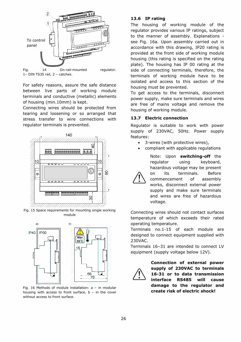
13.3 Assembly of control panel
Control panel is designed to be attached to a
mounting plate. Provide appropriate heat
insulation between hot boiler walls and
control panel and cable harness. Space
required to assemble control panel of the
regulator is shown in Fig. 24. When installing
follow the instructions given below.

25
Drill a hole in the mounting plate acc. the
below drawing.
Fig. 12 Installation of control panel in mounting plate
Fig. 13 Control panel mounting requirements. 1 –
control panel,
2 – vent holes to provide air circulation (note: the holes
may not cause downgrading of required IP rating. They
are not required if permitted ambient temperature
around the control panel is not exceeded.)
13.4 Disassembly of control panel
To remove the control panel (1) from the
housing - insert flat elements (2) into
indicated slots to release housing catches
and remove the panel (1).
13.5 Mounting of working module
Module housing does not assure dust- or-
waterproofness. To provide the required
protection, appropriate module cover should
be provided. Assembly shall assure IP rating
appropriate to the environment conditions, in
which the regulator will operate. Moreover,
access of the user to live parts under
hazardous voltage (e.g. terminals) shall be
prevented. Standard housing may be used to
accommodate the regulator. In such case the
user will have access to front surface of
working module. Housing may be also
formed by boiler elements surrounding the
whole module- see Fig. 16b. Space required
for mounting a single working module is
shown in Fig. 15.
The working module is designed to be
mounted on standard DIN TS35 rail. Fasten
the rail firmly to a rigid surface. Prior to
placing the modules on the rail (1) - lift up
the catches (2) using screwdriver - see
Fig.15.
Now, place the modules on the rail and press
the catches (2) to bring them to original
position. Make sure the device is firmly
fastened and cannot be easily removed from
the rail without use of tools.
26
Fig. 14 On-rail-mounted regulator.
1– DIN TS35 rail, 2 – catches.
For safety reasons, assure the safe distance
between live parts of working module
terminals and conductive (metallic) elements
of housing (min.10mm) is kept.
Connecting wires should be protected from
tearing and loosening or so arranged that
stress transfer to wire connections with
regulator terminals is prevented.
Fig. 15 Space requirements for mounting single working
module
Fig. 16 Methods of module installation: a – in modular
housing with access to front surface, b – in the cover
without access to front surface.
13.6 IP rating
The housing of working module of the
regulator provides various IP ratings, subject
to the manner of assembly. Explanations -
see Fig. 16a. Upon assembly carried out in
accordance with this drawing, IP20 rating is
provided at the front side of working module
housing (this rating is specified on the rating
plate). The housing has IP 00 rating at the
side of connecting terminals, therefore, the
terminals of working module have to be
isolated and access to this section of the
housing must be prevented.
To get access to the terminals, disconnect
power supply, make sure terminals and wires
are free of mains voltage and remove the
housing of working module.
13.7 Electric connection
Regulator is suitable to work with power
supply of 230VAC, 50Hz. Power supply
features:
3-wires (with protective wires),
compliant with applicable regulations
Note: Upon switching-off the
regulator using keyboard,
hazardous voltage may be present
on its terminals. Before
commencement of assembly
works, disconnect external power
supply and make sure terminals
and wires are free of hazardous
voltage.
Connecting wires should not contact surfaces
temperature of which exceeds their rated
operating temperature.
Terminals no.1-15 of each module are
designed to connect equipment supplied with
230VAC.
Terminals 16–31 are intended to connect LV
equipment (supply voltage below 12V).
Connection of external power
supply of 230VAC to terminals
16-31 or to data transmission
interface RS485 will cause
damage to the regulator and
create risk of electric shock!
To control
panel

27
Endings of connecting wires (particularly
power supply ones) have to be protected
from lamination using insulated clamping
sleeves shown on the drawing below:
Fig. 17 Wire ending protection:
a) correct, b) incorrect
Connect power supply wires to terminals
indicated with an arrow.
13.8 Protective connection
Connect protective wire of power supply
cable to ground strip linked with metal boiler
housing. Connect coupling to the terminal of
the regulator indicated with a sign and to
earthing terminals of devices connected to
the regulator.

28
Fig. 18 Wiring diagram of sensors for A and B module.
For safety reasons, the regulator shall be equipped with the set of pins
inserted to 230 VAC power supply connectors, even in case no load is
connected to the given strip.

29
Fig. 19 Wiring diagram for module C(MX.03): T1 – mixer circuit temperature sensor (type: CT4), T2 – mixer circuit
temperature sensor (type: CT4), T – room thermostat, ! – use only two wires for connection (do not make connection
using four wires - risk of regulator damage), A – ecoMAX810P3-L TOUCH main regulator, P3; power supply cable 230VAC,
Z – jumper (insulated electric connection), SM – mixer servo, PM – mixer pump, PC – HUW circulating pump, GR –
ground strip.

30
13.9 Connection of temperature
sensors
Regulator works with sensors -type: CT4 and
CT2S only. Use of other sensors is not
allowed.
Sensor wires may be extended using wires of
cross-section area not less than 0.5 mm2.
Total length of wires of each sensor should
not exceed 15 m.
Insert boiler temperature sensor into
thermometer well fastened to boiler shell.
Fasten feeder temperature sensor to the
surface of feeder screw tube. Insert
temperature sensor of HUW container into
thermometer well welded to the container.
The best way to mount mixer temperature
sensor is to insert it into a sleeve located in
the stream of flowing water, however, it is
also allowed to fasten the sensor in a contact
manner provided that the sensor and the
pipe are properly heat-insulated.
Sensors shall be protected against
loosening from surfaces they are
mounted to.
Make sure thermal contact between the
sensors and the surface which temperature is
measured is good. Apply thermal paste to
improve the contact. Pouring sensors with oil
or water is not allowed.
Sensor wires should be separated from
power supply wires. Otherwise, temperature
indications may be erroneous. Min. distance
between these wires should be 10 cm.
Do not allow sensor wires to contact hot
parts of the boiler and heating system. Wires
of temperature sensors are heat resistant to
the temperature not exceeding 100°C.
13.10 Connection of weather sensor
Regulator works with weather sensors -type:
CT4-P only. Fasten the weather sensor on
the coldest wall of the building - usually it is
a roofed area of north wall. The sensor
should not be exposed to direct sunlight or
rainfall. Install the sensor at the height of
min. 2 m above ground level in the location
away from windows, chimneys and other
heat sources, which may interfere
temperature measurements (min.
distance:1.5 m).
Use cable of wire with cross section area of
min. 0.5 mm2 and length of up-to 25 m to
connect the sensor. Wire polarization is
irrelevant. Connect other cable end to
regulator terminals as shown in Fig. 18.
Bolt the sensor to the wall using erection
bolts. Holes for bolts are accessible upon
removal of sensor housing lid.
Fig. 20 Connection of weather sensor CT4-P.
13.11 Testing of temperature sensors
CT4/CT4-P/CT2S temperature sensors may
be tested by measuring their resistance at
the given temperature. In case of significant
differences between the measured resistance
and the values indicated in the table below -
replace the sensor.
Regulator works with exhaust temperature
sensors - type: CT2S only. To test CT2S
sensor use very accurate multimeter –
otherwise, only very rough testing is
possible.

31
CT4
Temp.
°C Min.
Ω Rated
Ω Max.
Ω
0 802 815 828
10 874 886 898
20 950 961 972
25 990 1000 1010
30 1029 1040 1051
40 1108 1122 1136
50 1192 1209 1225
60 1278 1299 1319
70 1369 1392 1416
80 1462 1490 1518
90 1559 1591 1623
100 1659 1696 1733
CT4-P
Temp.
°C Min.
Ω Rated
Ω Max.
Ω
-30 609 624 638
-20 669 684 698
-10 733 747 761
0 802 815 828
10 874 886 898
20 950 961 972
CT2S
Temp.
°C Min.
Ω Rated
Ω Max.
Ω
0 999,7 1000,0 1000,3
25 1096,9 1097,3 1097,7
50 1193,4 1194,0 1194,6
100 1384,2 1385,0 1385,8
125 1478,5 1479,4 1480,3
150 1572,0 1573,1 1574,2
13.12 Connection of mixers room
thermostat
Room thermostats connected to working
module B acc. Fig. 18 affect circuits of mixer
1 and 2. If the whole heating system of the
building is supplied through a mixer, all
settings of room thermostat for the boiler
should be OFF.
Room thermostat with open contacts reduces
preset temperature of mixer circuit by the
decrement set in:
Mixer 1 settings > Mixer room
thermostat
Select the value of this parameter so that
once the room thermostat has responded (its
contacts have opened), the temperature in
the room drops.
Other settings - see sec. 8.16
13.13 Connection of reserve boiler
Regulator may control reserve oil or gas fired
boiler. In such case, manual start and stop of
reserve boiler is not necessary. Reserve
boiler starts once the temperature of pellet
fired boiler has dropped and stops it has
reached a proper value. Reserve (e.g. gas
fired) boiler should be connected by qualified
technician in accordance with technical
documentation of this boiler.
Reserve boiler should be electrically
connected through relay to terminals 30-31
of working module of the regulator - see Fig.
2418 and Fig. 1821.
Fig. 21 Example: connection of reserve boiler to
ecoMAX810P3-L TOUCH regulator 1- ecoMAX810P3-L
TOUCH regulator - module B, 2 – reserve (gas- or oil-
fired) boiler, 3 – U3 module composed of RM 84-2012-
35-1006 relay and GZT80 RELPOL base plate.
Standard version of the regulator is not
equipped with U3 module. Components of U3
module are offered for sale by the
manufacturer of ecoMAX810P3-L TOUCH
regulator.
U3 module should be assembled
and mounted by the user with
observance of applicable
regulations.
To activate control of reserve boiler - set CH
temperature at which the boiler will start.
SERVICE SETTINGS > BOILER
SETTINGS > Reserve boiler
Control of reserve boiler is disabled upon
setting the temperature of its stop at "0”.
B

32
Once the pellet-fired boiler has been fired-up
and its temperature has exceeded preset
value e.g. by 25 C, ecoMAX810P3-L TOUCH
regulator stops reserve boiler (supplies 6VDC
voltage to terminals 30-31 of module B). Coil
of U3 module relay energizes and relay
contacts open. Once the boiler temperature
has dropped below the value set in the
parameter of Reserve boiler deactivation
temperature, regulator stops to supply
voltage to terminals 30-31, and reserve
boiler switches on.
Entry of regulator to OFF mode
causes the reserve boiler switches
on.
It is recommended to change-over
ecoMAX810P3-L TOUCH regulator to OFF
mode once the pellet boiler has failed and
there is a need to use reserve boiler. In OFF
mode, control of CH system is disabled
(mixer, HUW and boiler pumps and mixer
control are inactive).
Fig. 22 Hydraulic diagram with reserve boiler;
connection of open and close circuits 1 – regulator
ecoMAX, 2 – reserve boiler,3 – module U3,
4 – switching valve (with limit switches), 5 – heat
exchanger - recommended settings: HUW priority
= OFF, CH pump =boiler pump = YES.
Fig. 23 Hydraulic diagram with reserve boiler and
4-way valve in close circuit. 1 – regulator ecoMAX,
2 – reserve boiler, 3 – module U3, 4 – switching
valve servo (with limit switches)
Fig. 24 Wiring diagram of control of switching valve
in reserve boiler. 1 – ecoMAX810P3-L TOUCH
regulator module B, 2 – reserve boiler, 3 –
module U3, 5 – switching valve servo (with limit
switches).
13.14 Connection of alarm announcing
Regulator may announce alarm conditions by
activating external device (e.g. bell or GSM
device to send SMS).
B

33
Connect alarm annunciator as shown in the
figure below through relay (3) to
ecoMAX810P3-L TOUCH regulator - module A
(1).
Fig. 25 Connection of external alarm annunciator. 1-
ecoMAX810P3-L TOUCH regulator - module A, 2 –
external alarm annunciator, 3 – relay (e.g.RM 84-2012-
35-1012 RELPOL) with GZT80 RELPOL base plate.
For proper operation, set proper value of the
parameter: Active alarm signal code in:
SERVICE SETTINGS > BOILER SETTINGS
> Alarms
When "127" has been set - in case of any
alarm occurred, voltage is applied between
contacts 30-31 (alarm output is ON). Setting
this parameter at "0" causes the regulator to
not activate the output in case of occurrence
of any alarm.
Alarm output may be also set up to activate
upon occurrence of one or more specifically
selected alarms. The values of this
parameter to be set for respective alarms are
given in the table below:
Exhaust
tem
pera
ture
sensor
dam
age
Excess o
f boiler
tem
pera
ture
Excess o
f fe
eder
tem
pera
ture
CH
boiler
tem
pera
ture
sensor
dam
age
Feeder
tem
pera
ture
sensor
dam
age
Unsuccessfu
l boiler
firing-u
p a
ttem
pt
Fan d
am
age
AL 1 AL 2 AL 3 AL 4 AL 5 AL6 AL7
1 2 4 8 16 32 64
Example: when this parameter is set at "8”,
alarm output is activated only upon
occurrence of AL4 alarm. Setting "1”
activates the output only in case of AL1
alarm. In case the output should signal few
selected alarms (e.g. AL2 and AL4 alarms) -
sum-up the values indicated in the table for
individual alarms (i.e. 2 + 8 = 10) and set
this parameter at this value. If any of the
alarms AL1, AL2, AL3 should be announced-
set this parameter at "7”.
13.15 Connection of mixer
The regulator works only with mixing valve
servos equipped with limit switches. Use of
other servos is not allowed. The servos of full
turn time from 30 to 255 s may be used.
Description of mixer connection:
- disconnect power supply to the regulator,
- determine direction of servo closing/
opening and connect electrically mixer and
regulator acc. technical documentation (be
careful - do not mistake direction of valve
opening with its closing)
- connect mixer temperature sensor and
mixer pump,
- switch on the regulator and set proper time
of valve opening (indicated in servo
documentation) in mixer service setting:
SERVICE SETTINGS > Mix1 settings >
Valve full opening time
- connect power supply to the regulator and
switch on the regulator to start the mixer
pump,
- verify whether the servo opens in correct
direction (to do this - enter the menu Info
and the tag of selected mixer or use the
option to control manually equipment
connected to the regulator. If the mixer does
not open in correct direction - change wiring
(disconnect power supply to the regulator at
first).
13.16 Connection of circulating pump
Circulating pump may be connected to
ecoMAX810P3-L TOUCH boiler regulator only
upon installing the extension of working
module.

34
13.17 Connection of STB temperature
limiter
To avoid boiler overheating in case of
regulator failure, STB or other safety
temperature limiter proper for the given
boiler has to be provided.
Connect STB limiter to terminals 1-2 of
working module shown in Fig. 18. Once the
limiter has tripped, fan and fuel feeder motor
are OFF.
Safety temperature limiter should
be suitable to operate at rated
voltage min.230V AC and hold
required certificates of approval.
In case the limiter is not installed- bridge the
terminals 1-2 using insulated wire of cross-
section area of min.0.75 mm2 with insulation
enough thick to meet safety requirements for
the boiler.
Acc. recent regulations, use of
safety temperature limiters is
mandatory.
13.18 Connection of room control panel
Regulator may be equipped with ecoSTER-
TOUCH room control panel, which may
perform following functions:
room thermostat,
boiler control panel
alarm annunciator,
fuel level indicator.
Note: Cross-section area of wires
used to connect ecoSTER-TOUCH
control panel should be of min.
0.75mm2 and its max. length
should not exceed 30 m.
This length may be longer if the wires used
have cross-section area larger than 0.75mm2
4-wire connection:
2-wire connection:
For two-wire connection, power supply of 5 V
DC and rated current of min. 500 mA is
required.
Points to supply ecoSTER-TOUCH:
Connect GND and +5 V to external source of
supply5.
Connect lines D+ and D- acc. wiring diagram
provided below.
5 PS unit is not included in the regulator
supply.

35
14 BOILER SERVICE SETTINGS
14.1 Firing-up
All parameters, which affect firing-up process
are grouped in the menu:
SERVICE SETTINGS >
BOILER SETTINGS > FIRING-UP
Details of the parameters, which are
responsible for firing-up process are given in
sec. 8.4.
14.2 Burining-off
All parameters, which affect burning-off
process are grouped in the menu:
SERVICE SETTINGS >
BOILER SETTINGS > BURNING OFF
Details of the parameters, which are
responsible for burning-off process are given
in sec. 8.9.
14.3 Supervision time
It is the max. time over which the regulator
remains in SUPERVISION mode. If there is
no need to start heating again within this
period of time, the regulator automatically
proceeds to burning-off mode (see sec. 8.8).
Setting this parameter at „0”
disables SUPERVISION mode, and
regulator proceeds directly from
OPERATION to BURNING OFF mode.
14.4 Feed. time SUPERV.
It is the time of fuel feeding and fan
operation in SUPERVISION mode - see sec.
8.8.
Setting this parameter at „0”
causes that only fan will be ON in
SUPERVISION mode.
Value of this parameter may not be
too high because it may lead to
boiler overheating in SUPERVISION
mode. In SUPERVISION mode,
boiler temperature must slowly
drop.
14.5 Feeder Intercal SUPERV.
It is the time of fuel feeding interruption in
SUPERVISION mode -see sec. 8.8.
Value of this parameter may not be
too small because it may lead to
boiler overheating in SUPERVISION
mode. In SUPERVISION mode,
boiler temperature must slowly
drop.
14.6 Airflow oper. extend. in
SUPERVISION mode
In SUPERVISION mode of boiler operation,
once the fuel dose has been supplied and the
feeder stopped, the fan remains in operation
for a time set in "Airflow oper. extend." to
fire-up the fuel dose supplied.
Setting this parameter at "0”
causes the fan to be OFF in
SUPERVISION mode.
Value of this parameter may not be
too high because it may lead to
boiler overheating in SUPERVISION
mode. In SUPERVISION mode,
boiler temperature must slowly
drop.

36
14.7 Thermostat selection
SERVICE SETTINGS > BOILER SETTINGS
> Thermostat selection
This option enables selection of room
thermostat for boiler circuit in case ecoSTER
room control panel is connected or
mechanical thermostats connected to
working module B are used. Following
options are available:
- OFF ,
-Standard 1 – standard NO/NC thermostat
connected to terminals 26-27 of module B,
-Standard 2 – standard NO/NC thermostat
connected to terminals 28-29 of module B,
- ecoSTER1 – thermostat 1 in ecoSTER,
- ecoSTER2 – thermostat 2 in ecoSTER,
- ecoSTER3 – thermostat 3 in ecoSTER.
If ecoSTER is not connected, only options
related to operation with standard room
thermostats are available in the menu.
14.8 Min. preset boiler temperature
This parameter is used to prevent the user to
set too low value of preset boiler
temperature. Boiler operation at too low
temperature may cause its quick damage,
corrosion, dirt, etc. The algorithms, which
automatically reduce the temperature, do not
cause the fall of preset boiler temperature
below the minimum value configurable in this
parameter.
Set this value acc. recommendation
of boiler manufacturer
14.9 Max. pre-set boiler temperature
This parameter is used to prevent the user to
set too high value of preset boiler
temperature.
The algorithms, which automatically increase
the temperature (correction acc. heating
curve or to required HUV temperature), do
not cause the increase of boiler temperature
above the maximum value configurable in
this parameter.
Set this value acc. recommendation
of boiler manufacturer.
14.10 Min. blow-in output
During first start-up of the boiler, set the
minimum blowing power, which may be
selected by the user.
SERVICE SETTINGS > BOILER SETTINGS
> Minimum blow-in output
This parameter protects the fan from
damage caused by operation with too low
rotary speed. Min. blowing power should be
set basing upon observations of fan
behaviour; some reserve should be also
considered.
Upon setting e.g. 20% the user will be able
to set the blowing power not less than 20%.
14.11 No fuel detection time
Lack of fuel in main boiler bin may be
detected by the regulator basing upon
exhaust temperature. In case the exhaust
temperature has been lower than the value
set in the parameter
SERVICE SETTINGS > BOILER SETTINGS
> Ex.temp.w.no fuel
over the time longer than the value set in the
parameter:
SERVICE SETTINGS > BOILER SETTINGS
> No fuel detection time
the regulator proceeds from OPERATION do
FIRING-UP. If there is no fuel in the bin,
FIRING-UP process will be concluded with a
message "furnace fire-up is impossible".
14.12 Maximum feeder temperature
It is the temperature at which the protection
against flashback to fuel feeder trips. This
function is described in sec. 22.3
Setting Maximum feeder
temperature at "0” enables
disconnection of feeder sensor and
regulator operation without this
sensor. Nevertheless, this setting is
not recommended because
flashback prevention function is
disabled.
14.13 Poker cycle time
Poker operation is set in the parameter:
SERVICE SETTINGS > BOILER SETTINGS
> Poker cycle time

37
This parameter determines the time required
to move away the poker only. Full poker
cycle time is twice so long, because the
poker has to return to its home position upon
completion of work.
14.14 Reserve boiler
The temperature of pellet-fired boiler at
which reserve boiler (e.g. gas fired boiler)
will switch off is set using this parameter.
Details - see sec.13.15.
14.15 Boiler cooling temp.
The temperature at which preventive boiler
cooling will start. Detailed description of this
procedure in provided in sec.22.2.
It is recommended to set Boiler
cooling temp. at the value below the
value at which safety temperature
limiter will trip to avoid interruptions
of boiler operation caused by
overheating.
14.16 A, B, C parameters of Individual
Fuzzy Logic
A, B and C parameters of Individual Fuzzy
Logic decide how fast the boiler temperature
will reach its pre-set value and affect stability
in keeping the preset boiler temperature in
Individual Fuzzy Logic mode. These
parameters have no effect on combustion
quality in IndividualFuzzyLogic mode,
because it is automatically controlled.
Change of these parameters is not
recommended if boiler output change rate is
satisfactory.
Parameter
A
The higher this value is the higher
the boiler output increase rate is.
The higher this value is the faster
the boiler temperature approaches
the preset value. Too high value
may cause instability in keeping
the preset boiler temperature.
Available setting range: 6…8,
recommended set value: 6.
Parameter
B
The higher this value is the lower
the boiler output increase rate is.
The higher this value is the slower
the boiler temperature approaches
the preset value. Setting higher
value gives more probability that
oscillations of preset boiler
temperature will not occur. Too low
value may cause instability in
keeping the preset boiler
temperature. Available setting
range: 20…30, recommended set
value: 30.
Parameter
C
Proper setting of this parameter
enables improvement of stability in
keeping the preset boiler
temperature. Too high value set
may result in large fluctuations of
boiler temperature. Change of
factory setting is not
recommended.
15 CH AND CUW SERVICE SETTINGS
15.1 CH pump activation temperature
This parameter determines the temperature
at which CH pump will be activated. Once the
temperature set in the parameter CH pump
activation temperature has been reached,
the CH pump is activated. This protects the
boiler from dew caused by cold water
returning from the system.
Switching-on of CH pump only does
not guarantee protection of the
boiler from dew and from the
resulting corrosion.
Additional automation equipment
(e.g. 4-way valve) should be used.
15.2 CH pump standstill at HUW
loading
Too long time of HUW container filling at
active HUW priority may lead to excessive
cooling down of CH system because CH
pump is switched off at these settings.
The parameter of CH pump standstill time
during HUW filling prevents it by periodic CH
pump activation during HUW container filling.
CH pump starts, runs over a fixed time set at
30s, stops for the time set in this parameter
and starts again.
15.3 Min HUW temperature
This parameter is used to prevent the user to
set too low pre-set HUW temperature.
15.4 Max HUW temperature
This parameter defines max. temperature to
which HUW container will be heated-up
during discharge of excess heat from the
boiler in emergency conditions. This

38
parameter is very important, because setting
of too high value may cause the risk of
burning the users with hot utility water. On
the other hand, too low value of this
parameter will cause that in case of boiler
overheating excessive heat cannot be
removed to HUW container.
When designing HUW system,
possibility of regulator failure should
be considered. In case of regulator
failure, water in HUW container may
heat-up to hazardous temperature,
which may create the risk of
burning.
THEREFORE, SOME OTHER
PROTECTION (E.G. THERMOSTATIC
VALVES) SHOULD BE USED.
15.5 Increase of boiler temperature by
HUW, mixer circuit and buffer
status
This parameter determines by how many
degrees the preset boiler temperature will be
increased to fill HUW container, buffer and
mixer circuit. Temperature is increased only
if required. Once the preset boiler
temperature has reached sufficient value to
fill HUW container, buffer and mixer circuit,
the regulator stops its further increase.
The process of increasing preset
boiler temperature to fill HUW
container is indicated by "C" letter
on main display.
15.6 HUW operations ext.
Once HUW container has been filled and
HUW pump has been stopped, a boiler
overheating risk may occur. It occurs in case
the pre-set HUW temperature is higher than
the pre-set boiler temperature. This issue
refers particularly to the operation of HUW
pump in SUMMER mode, when CH pump is
OFF. To cool down the boiler, HUW pump
operation may be extended by the time set
in "HUW pump operation extension time.
It is not recommended to set this
parameter at the value other than
"0" if preset HUW temperature is
lower than preset boiler
temperature.
15.7 Heat exchanger
When the parameter Heat exchanger is set
at ,YES”, CH pump does not stop, when HUW
priority is set nor in HUW SUMMER mode.
This parameter is intended only for hydraulic
systems with heat exchangers, where HUW
container is installed at the side of closed
circuit, and heat exchanger isolates open
boiler circuit from close CH circuit.
Continuous pump operation allows heat
transfer from the boiler through the heat
exchanger to HUW container.
16 MIXER SERVICE SETTINGS
16.1 MIXER SUPPORT
Following options are available:
OFF – mixer servo and mixer are OFF,
ON – is used when the mixer circuit supplies
CH radiator system. Max. temperature of
mixer circuit is not limited and mixer is fully
opened during alarms e.g. boiler
overheating.
Note: do not activate this option if the
pipes used are not high-temperature
resistant. In such conditions it is
recommended to set "MIXER SUPPORT"
at "Floor On.
Floor On – is used when the mixer circuit
supplies underfloor heating system. Max.
temperature of mixer circuit is limited to the
value set in the parameter of Max. pre-set
mixer temp.
Note: upon selection of the option of Floor
On" set the parameter Max. preset mixer
temp. at such value, which will prevent the
floor destruction and occurrence of burn risk.
Pump only – once the mixer circuit
temperature has exceeded the value set in
"mixer preset value", power supply to the
mixer pump stops. Once the mixer circuit
temperature has dropped by 2 ºC, the pump
switches on again. This option is mainly used
to control the underfloor heating pump in
case it works with thermostatic valve without
servo. However, it is not a recommended
manner of operation. It is recommended to
use a standard heating circuit composed of
valve, servo and mixer pump for underfloor
heating. Other possible solution is the use of

39
mixer pump to protect boiler return
temperature by means of a pump combining
boiler supply and return. In such case, the
use of mixer support is prevented.
16.2 Thermostat selection
This option enables changing room
thermostat for the mixer circuit in case
ecoSTER room control panel is connected.
Following options are available:
- Standard 1 – standard NO/NC thermostat
connected to terminals 26-27 or 28-29 for
mixer 1 and 2, respectively,
- ecoSTER1 – thermostat 1 in ecoSTER,
- ecoSTER2 – thermostat 2 in ecoSTER,
- ecoSTER3 – thermostat 3 in ecoSTER.
If ecoSTER is not connected, regulator works
with a standard room thermostat.
16.3 Min. preset mixer temperature
This parameter is used to prevent the user to
set too low preset value of mixer circuit
temperature. Automatic regulation (e.g.
temporary reduction of temperature) does
not cause the drop of preset temperature
below the value set in this parameter, either.
16.4 Max. preset mixer temperature
This parameter has two functions:
- it prevents the user to set too high value
of preset mixer temperature, Automatic
regulation (correction acc. heating curve or
to required outside temperature) does not
cause the increase of preset temperature
above the value set in this parameter, either.
- when the parameter "Mixer support" is set
at "FLOOR ON, it determines the limit value
measured by the mixer temperature sensor
at which the mixer pump will stop.
For underfloor heating set this
parameter at the value not
exceeding 45 C - 50 C unless the
manufacturer of materials used to
complete the floor or CH system
designer has recommended other
values.
16.5 Proportional range
Note: Change of this parameter is not
recommended.
It is the value of mixer stroke. The higher
the value is the faster the mixer circuit
achieves the preset value. Too high value of
this parameter may cause over-regulation
and unnecessary servo movements, which
reduce its lifetime.
Recommended settings of this parameter
should be within the range of 2 – 6 [factory
setting: 3].
16.6 Integr. time const.
Note: Change of this parameter is not
recommended.
This parameter determines mixer standstill
time in case the temperature measured by
the mixer circuit sensor is close to the value
preset for this circuit. The higher the value is
the longer the servo standstills are. Too high
value increases the time required to stabilize
the preset circuit temperature by servo.
Setting too low value may cause temperature
over-regulation and premature wear and tear
of servo.
Recommended settings of this parameter
should be within the range of 80 – 140
[factory setting:110].
16.7 Valve opening time
Enter the time of full valve opening taken
from the rating plate of valve servo (e.g.
140s)
16.8 Pump OFF by thermostat
Once this parameter has been set at "YES",
mixer servo closes and mixer pump stops
upon opening contacts of room thermostat
(room heating has been completed).
Performance of this operation is not
recommended because the heated room may
be cooled down too much.
17 SHOW ADVANCED SETUP
To display hidden parameters in menu
structure set the parameter:
Show advanced setup = YES.
This parameter is available in Menu >
Service Settings.
An example of this parameter is:
Mixer input dead zone, available in
Menu > Service Settings > Mixer
Settings.
18 SERVICE COUNTERS
One of the pages of Menu > Info provides
information of burner's operation hours,

40
number of ignitions, and fuel feeder's
operation time.
19 RESTORE FACTORY SETTINGS
To restore factory settings - select
Restore Default Settings and confirm the
selection.
This parameter is available in:
Menu > Service Settings
When restoring default settings,
service and user settings are also
restored.
20 Fan rotation detection
Regulator may check fan status using
rotation sensor. In case the fan has stopped
(e.g. because of damage), alarm is produced
- see sec.22.9.
21 Lambda sensor
Burner efficiency may be increased by
connection of additional Lambda sensor. How
to connect - see Fig. 19. Configure Lambda
sensor operation in:
Menu > SERVICE SETTINGS >
BOILER SETTINGS > Lambda sensor
If the parameter: Operation with Lambda
sensor is set at „ON”, the regulator will work
using lambda sensor indications. The amount
of air supplied to the furnace will be set
automatically to obtain the set value of
oxygen concentration in exhaust. If this
parameter is set at „OFF ” - lambda sensor
indications will have no effect on regulator
operation. Desired values of oxygen
concentration are set in:
Menu > Service Settings > BOILER
SETTINGS > Output Modulation
100% Blow-in output
100% Feeder operation
100% Feeder Interval
100% Oxygen
50% Blow-in output
50% Feeder operation
50% Feeder Interval
50% Oxygen
30% Blow-in output
30% Feeder operation
30% Feeder Interval
30% Oxygen
Description of other parameters related to
lambda sensor:
Airflow correction range - determines
permitted range of blowing power variation
for operation with lambda sensor. Note: do
not set too high values because it may
adversely affect regulation process.
Parameters A, B, C Lambda affect the
adjustment speed of oxygen value present in
exhaust to the preset oxygen concentration
value; it also affects the stability to keep the
oxygen content in exhaust. Change of these
parameters is not recommended if the
adjustment speed and stability to keep the
set oxygen concentration value are
satisfactory.
Fuel detection: oxygen -this parameter
enables detection of fuel lack on the basis of
Lambda sensor indications. If the oxygen
level has been in excess of fuel lack
detection threshold - oxygen longer than
the time set in No fuel detection time -
regulator attempts again to fire- up the
furnace, and if unsuccessfully - lack of fuel
alarm will be produced.
Feeder lock – this parameter determines
the oxygen concentration in exhaust below
which the feeder operation will be stopped
until another increase of this value.
After longer period of sensor operation, its
periodic calibration may be required. Before
calibration, the boiler has to be burnt-off.
Proper calibration requires complete burning
off the boiler furnace. To start calibration,
use the following parameter:
Menu > BOILER SETTINGS > Lambda
calibration
Calibration takes approx. 8 min.
22 ALARM DESCRIPTION
22.1 Exhaust temperature sensor
damage
This alarm occurs in case of damage of
exhaust temperature sensor and excess of its
measurement range. Upon alarm occurrence,
boiler operation is automatically stopped,
and only CH pump remains in operation.
To reset the alarm - confirm it or switch off
and on the regulator. Check the sensor and
replace, if necessary.
How to check temperature sensor -
see sec.13.11

41
22.2 Excess of max. boiler temperature
Protection against boiler overheating
comprises two stages. In first instance i.e.
once the Preventive boiler cooling temp. has
been exceeded, the regulator attempts to
reduce the boiler temperature by discharge
of excessive heat to HUW container and by
opening the mixer servos (only in case the
mixer circuit = CH ON).
Once the temperature measured by HUW
temperature sensor has exceeded the value
set in Max. HUW temp., HUW pump stops in
order to protect the user from burning with
hot utility water. Has the temperature
dropped - the regulator returns to normal
operation. In case the temperature is still
increasing (and has reached 95 C), power
supply to the fuel feeder and the fan is off
and permanent boiler overheating alarm with
sound signal is produced.
To reset the alarm - press Touch and Play
keys or switch the power supply to the
regulator off and on.
Note: arrangement of temperature
sensor outside the boiler water
jacket (e.g. at the outlet pipe) is
not recommended because boiler
overheating may be detected with
delay.
22.3 Excess of max. feeder
temperature
This alarm is produced once the feeder
temperature has exceeded the value set in
the service parameter:
SERVICE SETTINGS > BOILER
SETTINGS > Max. feedr temp.
If the feeder temperature exceeds this value,
the regulator activates the feeder for a fixed,
set time and the poker. The fan stops and
the pumps start. Once the fuel has been
"pushed out", the regulator stops the feeder
and does not activate it again even though
the feeder temperature remains high.
Alarm may be reset only upon drop of feeder
temperature. To reset the alarm - press
encoder knob or switch off and on power
supply to the regulator.
Flashback protection function is
inactive when the feeder sensor is
disconnected or damaged.
Flashback protection function is
disabled when power supply to the
regulator is disconnected.
ecoMAX810P3-L TOUCH regulator
may not be used as the only
flashback protection of the boiler.
Additional automatic safety devices
should be used.
Flashback protection function may
be disabled - see sec. 14.12.
22.4 Boiler temperature sensor
damage
This alarm occurs in case of boiler
temperature sensor damage and excess of
its measurement range. Upon occurrence of
this alarm, CH, HUW and mixer pumps start
to possibly cool down the boiler.
To reset this alarm - confirm it or switch off
and on power supply to the regulator. Check
the sensor and replace, if necessary
How to check temperature sensor -
see sec.13.11.
22.5 Feeder temperature sensor
damage
This alarm occurs in case of damage of fuel
feeder temperature sensor and excess of its
measurement range. Upon occurrence of this
alarm, CH and HUW pumps start to possibly
cool down the boiler.
To reset this alarm - confirm it or switch off
and on power supply to the regulator. Check
the sensor and replace, if necessary.
How to check temperature sensor -
see sec.13.11.
Upon setting of Max. feeder temp.
at '"0", the regulator may operate
without connected feeder
temperature sensor. However, it is
not a recommended manner of
operation because protection of the
boiler from flashback is disabled.
42
22.6 No communication
Control panel is connected with working
module by means of digital interface RS485.
In case connecting cable to this interface is
damaged, a message "Warning! No
communication” is displayed.
Regulator does not go off and works
normally with previously preset parameter
values, and in case of alarm occurrence it
takes action related to respective alarm
Check the cable, which connects the control
panel with the module and repair or replace,
if necessary.
22.7 Unsuccessful boiler firing-up
attempt
This alarm is produced after third
unsuccessful attempt of automatic furnace
firing-up. Upon occurrence of this alarm, all
pumps stop to avoid excessive boiler cooling.
To reset the alarm - confirm it or switch off
and on the regulator. The reason of this
alarm may be, among others, faulty heater
or lack of fuel in the bin.
22.8 Unsuccessful attempt of container
loading
It is so called "silent alarm prompt". It occurs
after unsuccessful attempt to charge the fuel
from additional bin (bunker). In case the
attempts to fill the boiler bin have been
unsuccessfully made within one full hour of
second feeder operation, this prompt is
displayed. It does not stop automatic boiler
operation, only warning message appears on
the control panel. To reset this alarm -
confirm it or switch off and on power supply
to the regulator.
22.9 Fan damage
In case of fan damage, a prompt "Damaged
fan” is displayed. Burner operation stops.
Note: the function of fan rotation detection
has to be enabled by the boiler
manufacturer.
23 OTHERS
23.1 Power failture
In case of power failure, the regulator
returns to the operation mode in which it was
before the failure.
23.2 Anti-freezing protection
In case the boiler temperature has fallen
below 5 C, CH pump is activated to force
boiler water circulation. It delays water
freezing process, but in case of very low
temperature or lack of power it may not be
sufficient to protect the equipment from
freezing.
23.3 Protection of pumps against
clogging
The regulator performs the function of CH,
HUW and mixer pump protection from
clogging caused by scale deposits. For this
purpose, these components are periodically
(every 167 h) switched on for a few seconds.
In this way the pumps are protected from
immobilization caused by scale deposits. For
this reason, power supply should be
connected to the regulator during boiler
standstill. This function is also active when
the regulator was switched off using the
keyboard (set at "OFF” mode).
24 REPLACEMENT OF PARTS AND
COMPONENTS
When ordering spare parts and components,
necessary information taken from the rating
plates should be provided. In case of
regulator – let us know its serial number, or,
if you are unable to provide it, specify
regulator model, version and year of
manufacture.
Serial number of the regulator is
quoted on rating plate of each
working module.
24.1 Replacement of mains fuse
Mains fuses are located in each working
module. They protect the regulator and other
connected equipment.
In case of replacement, use 6.3 A, 5x20mm
ceramic time fuse.

43
Fig. 26 Fuse replacement 1 – fuse, 2 – fuse
holder
To remove the fuse, press down fuse holder
using flat screwdriver and turn it in CCW
direction.
24.2 Replacement of control panel
In case of required replacement of control
panel only - make sure the software used in
new panel is compatible with the software of
working module. Compatibility is guaranteed
if first component of software ID number of
the panel and of the working module is the
same. In following example, software is
compatible because first component of its ID
number ("01") is the same for both
components.
Example of software ID number:
Control panel: Working module:
01.10.010. 01.11.026.R1
Software ID number may be taken
from the rating plate of respective
component or from Menu
Information
Incompatibility of control panel and
working module may cause
incorrect operation of the regulator.
24.3 Replacement of working module
The requirements are the same as for the
replacement of control panel - see sec.24.2.
24.4 Software up-grade
To up-grade the software - use micro SD
memory card or special interface ecoLINK II.
In this section, software up-grade using
memory card is described. To up-grade the
software - disconnect power supply to the
regulator and remove ecoTOUCH control
panel from the regulator housing acc. sec.
13.1. Insert memory card into indicated slot.
Memory card should contain new software in
*.pfc format (two files - one with software
for control panel, and the other one with
software for module "A" of the regulator).
Upload new software directly to memory
card. Do not nest data in sub-directory. Re-
install the control panel in regulator housing
and connect power supply. Enter:
General settings > Software Up-grade
and up-grade the software at first in module
A of the regulator, and next in the control
panel.
Fig. 27 Placing of microSD memory card

25 Troubleshooting
Faults Hints
The display is blank despite
connection to power supply.
Check:
if the main fuse is burnt-out, replace if so,
if the lead connecting the panel with the module is properly
plugged in, and if it’s not damaged.
Preset CH temperature on
the display is different than
the programmed one.
Check:
if the DHW tank is not being filled, and if the preset DHW
temperature is set higher than the preset boiler temperature; if
so, the difference in readings will disappear after filling the DHW
tank alternatively - decrease the preset DHW temperature,
if the time periods are on – disable Night-time decreases.
CH pump is inoperative.
Check:
whether the boiler temperature exceeded the parameter CH
activation temp. – wait or decrease the CH activation temp.
if the DHW priority, which blocks the central heating pump, is
enabled – disable the priority by setting the DHW mode to No
priority,
whether the central heating pump is not damaged or clogged.
The fan is inoperative.
increase the fan speed (parameters for blow-in output),
check if the safety temperature limiter STB jumper is on
terminals 1-2 (the jumper should be placed only if no proper STB
temperature limiter is connected),
if the boiler manufacturer equipped it with a temperature limiter
STB with manual return to its initial position, unlock it by
removing the lid and pushing the button, in accordance with the
documentation provided by the boiler manufacturer,
check the fan and replace it if necessary.
Fuel feeder inoperative/
fails to feed.
Check if the feeder leads are properly connected to terminals
If temperature limiter STB is connected to terminals 1-2, check if
the circuit is not cut off due to boiler overheating,
Check if the feeder motor is in working order,
If you can hear the motor running, but the fuel is not fed, check
the feeder in accordance with the boiler manual.
When the Individual Fuzzy
Logic mode is on, the fuel is
not completely burned,
there are unburned
particles of fuel in the ash.
Increase Individual Fuzzy Logic airflow correction, point 8.6,
See if the unburned fuel comes from operation in the
SUPERVISION mode - adjust the SUPERVISION mode
parameters,
Check if the unburned fuel is caused by frequent switching from
SUPERVISION to OPERATION,
Make sure if correct type of boiler is selected, point 26.1,
Open the fan flap and/or fan return flap to the maximum,
Check the ducts which feed air into the furnace,
Unseal the window in the boiler room to provide sufficient
amounts of air.
When the Individual Fuzzy
Logic mode is on, the fuel
burns out too intensively.
Decrease Fuzzy Logic airflow correction, point 8.6,
See if the excessive burning of fuel comes from operation in the
SUPERVISION mode - adjust the SUPERVISION mode as per
point 8.8.
Make sure if correct type of boiler is selected, point 26.1.

45
The temperature is
measured incorrectly.
Check if there is good thermal contact between the temperature
sensor and the measured surface,
Whether the sensor lead is not placed too close to the mains
cable,
If the sensor is connected to the terminal,
Whether the sensor is not damaged – check it in accordance with
point 13.11.
in the DHW=SUMMER
mode, the radiators are hot
and the boiler overheats.
Increase the parameter DHW operation extend. in order to cool
down the boiler.
the DHW pump is active
even if the DHW tank has
been filled.
Set the parameter DHW operation extend to 0.
The boiler overheats
despite disabled airflow.
The reason can be faulty chimney installation (no protection
against excessive chimney draught).
In a hydraulic system with
a mixing valve and servo -
the mixer fails to open.
The reason can be that the DHW tank is being filled with DHW
priority enabled. Wait until the DHW is filled, or disable the DHW
priority.
The reason can be active SUMMER function.
The reason can be an on-going calibration of the mixer valve,
wait until the calibration is complete. Active calibration is
signalled with a “CAL” message in the menu INFORMATION –
MIXER INFO.
26 Regulator setup by boiler manufacturer.
CAUTION: THE INDIVIDUAL FUZZY LOGIC PROGRAM IS SELECTED INDIVIDUALLY TO
THE GIVEN BOILER TYPE. MAKE SURE THAT THE FITTINGS FOR BOILERS TESTED IN
THE PLUM LABORATORIES ARE COMPATIBLE WITH FITTINGS FOR SOLD BOILERS. IT IS
INADMISSIBLE TO REPLACE THE FEEDER AND FAN TO OTHER TYPES AS WELL AS
MAKING OTHER CONSTRUCTIONAL MODIFICATIONS WHICH CAN HAVE IMPACT ON
COMBUSTION PROCESS.
26.1 Activating Individual Fuzzy Logic and changing boiler type
In order to activate the Individual Fuzzy Logic mode, enter menu:
Boiler settings> Output modulation > Regulation mode
In this menu, find and confirm Individual Fuzzy Logic mode If the boiler operation modes list is
unavailable, and clicking the aforementioned menu triggers a message “Function unavailable”, it
means that the regulator operates only in the STANDARD mode, Individual Fuzzy Logic control is
disabled and unavailable for the given setup of a boiler.
To change the type of boiler, furnace, enter hidden menu:
Service settings > [enter special password]
The special password is made available only to boiler manufacturers and authorized fitters.
Caution: selecting an incorrect boiler type, which was not examined in the
PLUM laboratories, can damage the boiler during its operation.
Settings for individual boilers require arrangements between the boiler manufacturer and the
PLUM sp. z o.o. company.
In order to apply the changes, it is necessary to disconnect and reconnect the regulator mains
supply.


47

Ignatki 27a, 16-001 Kleosin Poland
tel. +48 85 749-70-00 fax +48 85 749-70-14
www.plum.pl
www.plumelectronics.eu