Embed Size (px)
Citation preview

Installation& ServicingInstructions
THESE INSTRUCTIONSTO BE RETAINEDBY USER
ESS
ContentsDesign principles & operating sequence Page1.1 Principle components 21.2 Mode of operation (at rest) 21.3 Heat request mode 21.4 Safety devices 2
Technical data Page2.1 Central heating 32.2 Gas pressure 32.3 Expansion vessel 32.4 Dimensions 32.5 Clearances 32.6 Connections 32.7 Electrical 32.8 Flue details 32.9 Efficiency 32.10 Parameter defaults 32.11 Emissions 32.12 Pump duty 4
General requirements Page3.1 Related documents 43.2 Location of appliance 43.3 Gas supply 53.4 Flue system 53.5 Air supply 53.6 Water circulation 53.7 Electrical supply 63.8 Combustible surfaces 63.9 Timber framed buildings 63.10 Condensate disposal 63.11 Inhibitors 6
Installation Page4.1 Delivery 74.2 Contents 74.3 Unpacking 74.4 Preparation for mounting 74.5 Fitting the flue 74.6 Connecting the gas & water 104.7 Condensate outlet 114.8 Electrical connections 11
Commissioning Page5.1 Gas supply installation 125.2 The heating system 125.3 Initial filling of the system 125.4 Initial flushing of the system 125.5 Pre-operation checks 125.6 Initial lighting 125.7 Final flushing of the system 125.8 Operating parameters 135.9 Functional parameters 135.10 Range rating 135.11 Setting the system design pressure 135.12 Regulating the central heating system 135.13 Final checks 145.14 Instructing the user 14
Servicing Page6.1 General 146.2 Routine annual servicing 146.3 Replacement of components 146.4 Component removal procedure 146.5 Pump head removal 156.6 Safety valve removal 156.7 Automatic air valve removal 156.8 Pressure gauge removal 156.9 Temperature sensor removal 156.10 Main PCB removal 156.11 Gas valve removal 166.12 Fan removal 166.13 Burner removal 166.14 Electrode removal 166.15 Injector removal 166.16 Hydraulic manifold assembly 176.17 Condense trap removal 176.18 Condense pressure switch removal 176.19 Combustion cover removal 176.20 Expansion vessel removal 186.21 Input & status PCB removal 18
Checks, adjustments, and fault finding Page7.1 Checking appliance operation 197.2 Mode of operation 197.3 Checking/adjusting fan speeds 197.4 Adjusting the gas valve 207.5 Status code 217.6 Lockout faults codes 217.7 Diagnostic recall 217.8 Temperature sensor viewing mode 227.9 Checking the expansion vessel 227.10 External faults (installation) 227.11 Electrical checks 227.12 Fault finding 23
Wiring diagrams Page8.1 Important note 268.2 Installation of Vokera time clock 268.3 External controls 26
Exploded diagrams Page9.1 Table 1 319.2 Table 2 329.3 Table 3 339.4 Table 4 349.5 Table 5 35
L.P.G. instructions Page10.1 Technical data 3610.2 Related documents 3610.3 Gas supply 3610.4 Gas supply installation 3610.5 Adjusting the gas valve 3610.6 Range rating 37
1
INTRODUCTION
General layout
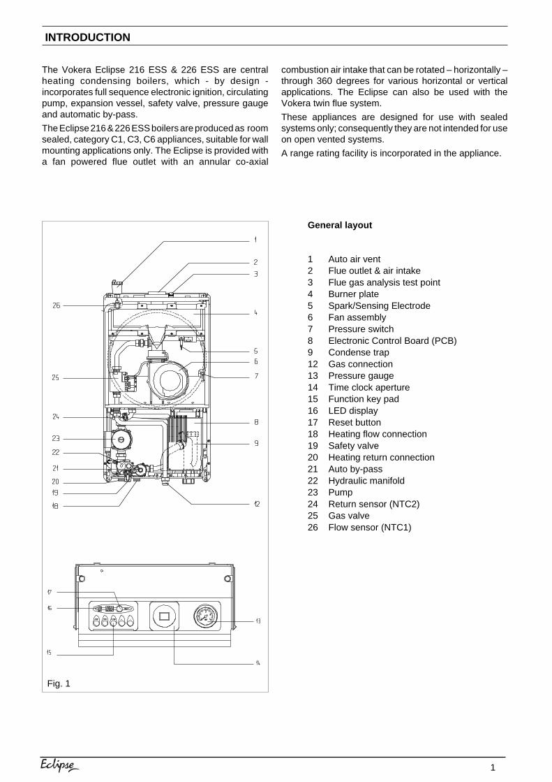
1 Auto air vent2 Flue outlet & air intake3 Flue gas analysis test point4 Burner plate5 Spark/Sensing Electrode6 Fan assembly7 Pressure switch8 Electronic Control Board (PCB)9 Condense trap12 Gas connection13 Pressure gauge14 Time clock aperture15 Function key pad16 LED display17 Reset button18 Heating flow connection19 Safety valve20 Heating return connection21 Auto by-pass22 Hydraulic manifold23 Pump24 Return sensor (NTC2)25 Gas valve26 Flow sensor (NTC1)
The Vokera Eclipse 216 ESS & 226 ESS are centralheating condensing boilers, which - by design -incorporates full sequence electronic ignition, circulatingpump, expansion vessel, safety valve, pressure gaugeand automatic by-pass.
The Eclipse 216 & 226 ESS boilers are produced as roomsealed, category C1, C3, C6 appliances, suitable for wallmounting applications only. The Eclipse is provided witha fan powered flue outlet with an annular co-axial
combustion air intake that can be rotated – horizontally –through 360 degrees for various horizontal or verticalapplications. The Eclipse can also be used with theVokera twin flue system.
These appliances are designed for use with sealedsystems only; consequently they are not intended for useon open vented systems.
A range rating facility is incorporated in the appliance.
Fig. 1
2
SECTION 1 DESIGN PRINCIPLES AND OPERATING SEQUENCE
1.1 PRINCIPLE COMPONENTS● A fully integrated electronic control board
featuring electronic temperature control,continuous air/gas modulation, anti-cyclecontrol, pump over-run, self-diagnostic faultindicator, electronic ignition with flamesupervision, & appliance frost protection.
● Cast aluminium mono-block heat exchanger.● Low Nox burner with pre-mix.● Two-stage gas valve.● Pump.● Expansion vessel.● Pressure gauge.● Safety valve.
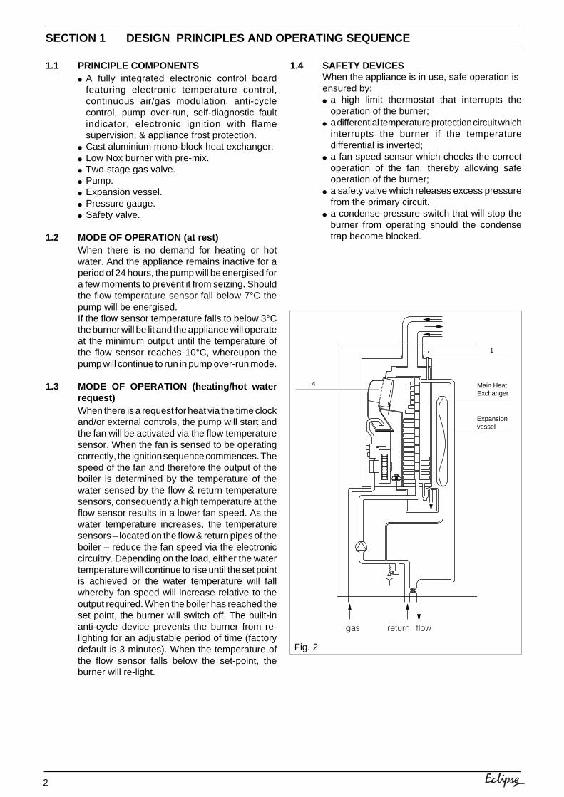
1.2 MODE OF OPERATION (at rest)When there is no demand for heating or hotwater. And the appliance remains inactive for aperiod of 24 hours, the pump will be energised fora few moments to prevent it from seizing. Shouldthe flow temperature sensor fall below 7°C thepump will be energised.If the flow sensor temperature falls to below 3°Cthe burner will be lit and the appliance will operateat the minimum output until the temperature ofthe flow sensor reaches 10°C, whereupon thepump will continue to run in pump over-run mode.
1.3 MODE OF OPERATION (heating/hot waterrequest)When there is a request for heat via the time clockand/or external controls, the pump will start andthe fan will be activated via the flow temperaturesensor. When the fan is sensed to be operatingcorrectly, the ignition sequence commences. Thespeed of the fan and therefore the output of theboiler is determined by the temperature of thewater sensed by the flow & return temperaturesensors, consequently a high temperature at theflow sensor results in a lower fan speed. As thewater temperature increases, the temperaturesensors – located on the flow & return pipes of theboiler – reduce the fan speed via the electroniccircuitry. Depending on the load, either the watertemperature will continue to rise until the set pointis achieved or the water temperature will fallwhereby fan speed will increase relative to theoutput required. When the boiler has reached theset point, the burner will switch off. The built-inanti-cycle device prevents the burner from re-lighting for an adjustable period of time (factorydefault is 3 minutes). When the temperature ofthe flow sensor falls below the set-point, theburner will re-light.
1.4 SAFETY DEVICESWhen the appliance is in use, safe operation isensured by:● a high limit thermostat that interrupts the
operation of the burner;● a differential temperature protection circuit which
interrupts the burner if the temperaturedifferential is inverted;
● a fan speed sensor which checks the correctoperation of the fan, thereby allowing safeoperation of the burner;
● a safety valve which releases excess pressurefrom the primary circuit.
● a condense pressure switch that will stop theburner from operating should the condensetrap become blocked.
Fig. 2
return flowgas
1
Main HeatExchanger
Expansionvessel
4
3
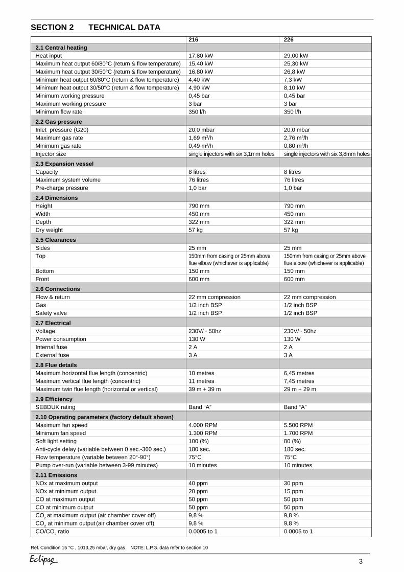
SECTION 2 TECHNICAL DATA
Ref. Condition 15 °C , 1013,25 mbar, dry gas NOTE: L.P.G. data refer to section 10
216 2262.1 Central heatingHeat input 17,80 kW 29,00 kWMaximum heat output 60/80°C (return & flow temperature) 15,40 kW 25,30 kWMaximum heat output 30/50°C (return & flow temperature) 16,80 kW 26,8 kWMinimum heat output 60/80°C (return & flow temperature) 4,40 kW 7,3 kWMinimum heat output 30/50°C (return & flow temperature) 4,90 kW 8,10 kWMinimum working pressure 0,45 bar 0,45 barMaximum working pressure 3 bar 3 barMinimum flow rate 350 l/h 350 l/h
2.2 Gas pressureInlet pressure (G20) 20,0 mbar 20,0 mbarMaximum gas rate 1,69 m3/h 2,76 m3/hMinimum gas rate 0,49 m3/h 0,80 m3/hInjector size single injectors with six 3,1mm holes single injectors with six 3,8mm holes
2.3 Expansion vesselCapacity 8 litres 8 litresMaximum system volume 76 litres 76 litresPre-charge pressure 1,0 bar 1,0 bar
2.4 DimensionsHeight 790 mm 790 mmWidth 450 mm 450 mmDepth 322 mm 322 mmDry weight 57 kg 57 kg
2.5 ClearancesSides 25 mm 25 mmTop 150mm from casing or 25mm above 150mm from casing or 25mm above
flue elbow (whichever is applicable) flue elbow (whichever is applicable)Bottom 150 mm 150 mmFront 600 mm 600 mm
2.6 ConnectionsFlow & return 22 mm compression 22 mm compressionGas 1/2 inch BSP 1/2 inch BSPSafety valve 1/2 inch BSP 1/2 inch BSP
2.7 ElectricalVoltage 230V/~ 50hz 230V/~ 50hzPower consumption 130 W 130 WInternal fuse 2 A 2 AExternal fuse 3 A 3 A
2.8 Flue detailsMaximum horizontal flue length (concentric) 10 metres 6,45 metresMaximum vertical flue length (concentric) 11 metres 7,45 metresMaximum twin flue length (horizontal or vertical) 39 m + 39 m 29 m + 29 m
2.9 EfficiencySEBDUK rating Band “A” Band “A”
2.10 Operating parameters (factory default shown)Maximum fan speed 4.000 RPM 5.500 RPMMinimum fan speed 1.300 RPM 1.700 RPMSoft light setting 100 (%) 80 (%)Anti-cycle delay (variable between 0 sec.-360 sec.) 180 sec. 180 sec.Flow temperature (variable between 20°-90°) 75°C 75°CPump over-run (variable between 3-99 minutes) 10 minutes 10 minutes
2.11 EmissionsNOx at maximum output 40 ppm 30 ppmNOx at minimum output 20 ppm 15 ppmCO at maximum output 50 ppm 50 ppmCO at minimum output 50 ppm 50 ppmCO2 at maximum output (air chamber cover off) 9,8 % 9,8 %CO2 at minimum output (air chamber cover off) 9,8 % 9,8 %CO/CO2 ratio 0.0005 to 1 0.0005 to 1
4
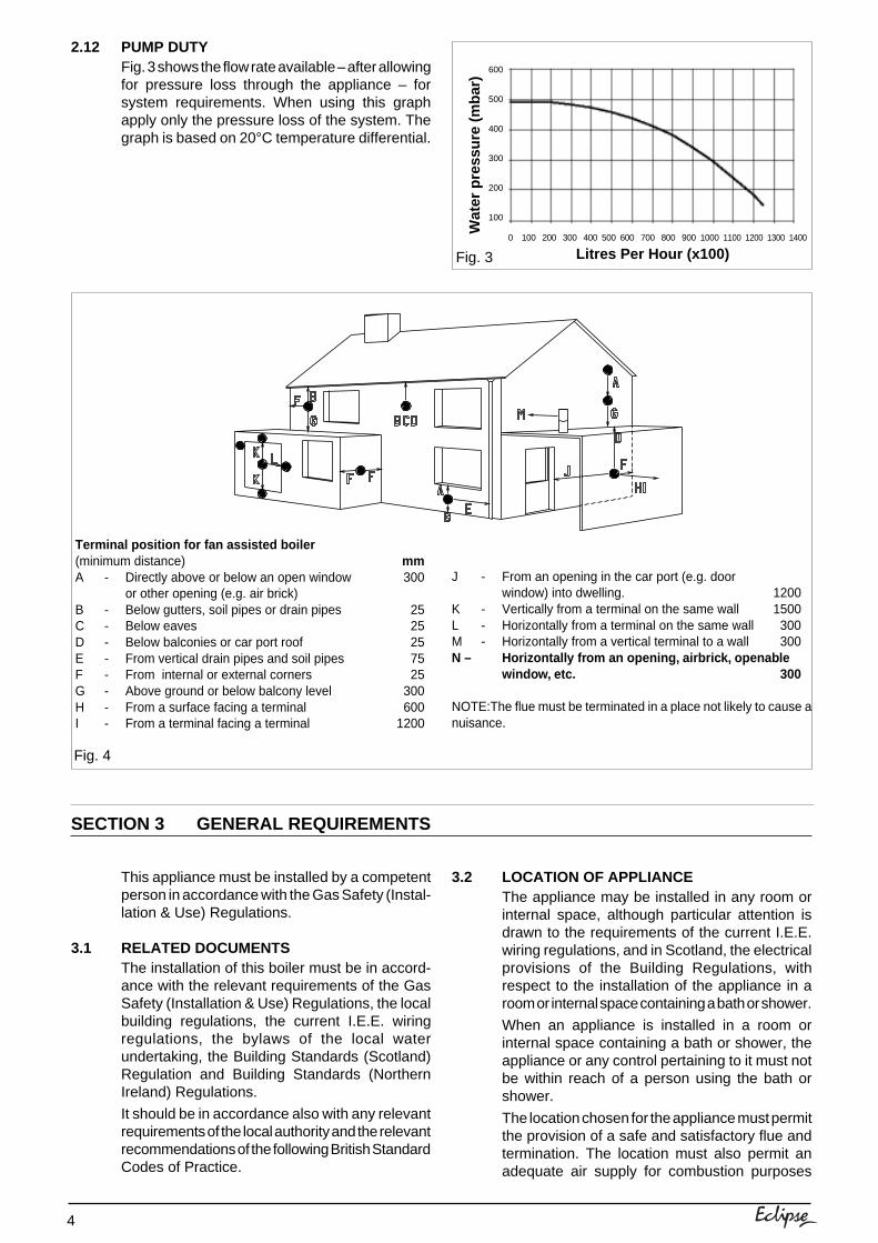
2.12 PUMP DUTYFig. 3 shows the flow rate available – after allowingfor pressure loss through the appliance – forsystem requirements. When using this graphapply only the pressure loss of the system. Thegraph is based on 20°C temperature differential.
Fig. 4
This appliance must be installed by a competentperson in accordance with the Gas Safety (Instal-lation & Use) Regulations.
3.1 RELATED DOCUMENTSThe installation of this boiler must be in accord-ance with the relevant requirements of the GasSafety (Installation & Use) Regulations, the localbuilding regulations, the current I.E.E. wiringregulations, the bylaws of the local waterundertaking, the Building Standards (Scotland)Regulation and Building Standards (NorthernIreland) Regulations.
It should be in accordance also with any relevantrequirements of the local authority and the relevantrecommendations of the following British StandardCodes of Practice.
Terminal position for fan assisted boiler(minimum distance) mmA - Directly above or below an open window 300
or other opening (e.g. air brick)B - Below gutters, soil pipes or drain pipes 25C - Below eaves 25D - Below balconies or car port roof 25E - From vertical drain pipes and soil pipes 75F - From internal or external corners 25G - Above ground or below balcony level 300H - From a surface facing a terminal 600I - From a terminal facing a terminal 1200
J - From an opening in the car port (e.g. doorwindow) into dwelling. 1200
K - Vertically from a terminal on the same wall 1500L - Horizontally from a terminal on the same wall 300M - Horizontally from a vertical terminal to a wall 300N – Horizontally from an opening, airbrick, openable
window, etc. 300
NOTE:The flue must be terminated in a place not likely to cause anuisance.
SECTION 3 GENERAL REQUIREMENTS
3.2 LOCATION OF APPLIANCEThe appliance may be installed in any room orinternal space, although particular attention isdrawn to the requirements of the current I.E.E.wiring regulations, and in Scotland, the electricalprovisions of the Building Regulations, withrespect to the installation of the appliance in aroom or internal space containing a bath or shower.
When an appliance is installed in a room orinternal space containing a bath or shower, theappliance or any control pertaining to it must notbe within reach of a person using the bath orshower.
The location chosen for the appliance must permitthe provision of a safe and satisfactory flue andtermination. The location must also permit anadequate air supply for combustion purposes
Fig. 3
Wat
er p
ress
ure
(mba
r)
Litres Per Hour (x100)0 100 200 300 400 500 600 700 800
600
500
400
300
200
100
900 1000 1100 1200 1300 1400

5
and an adequate space for servicing and aircirculation around the appliance.Where the installation of the appliance will be inan unusual location special procedures may benecessary, BS 6798 gives detailed guidance onthis aspect.
A compartment used to enclose the appliancemust be designed and constructed specificallyfor this purpose. An existing compartment/cup-board may be utilised provided that it is modifiedto suit.
Details of essential features of compartment/cupboard design, including airing cupboard in-stallations, are given in BS 6798. This applianceis not suitable for external installation.
3.3 GAS SUPPLYThe gas meter – as supplied by the gas supplier– must be checked to ensure that it is of adequatesize to deal with the maximum rated input of allthe appliances that it serves. Installation pipesmust be fitted in accordance with BS 6891.Pipe-work from the meter to the appliance must beof adequate size. Pipes of a smaller size than theappliance gas inlet connection must not be used.The installation must be tested for soundness inaccordance with BS 6891.
If the gas supply serves more than one appliance,it must be ensured that an adequate supply ismaintained to each appliance when they are inuse at the same time.
3.4 FLUE SYSTEMThe terminal should be located where the disper-sal of combustion products is not impeded andwith due regard for the damage and discolorationthat may occur to building products located nearby.The terminal must not be located in a place whereit is likely to cause a nuisance (see fig. 4).
Water vapour will condense on leaving the flueterminal, the effect of such pluming must beconsidered.
If installed less than 2m above a pavement orplatform to which people have access (includingbalconies or flat roofs) the terminal must beprotected by a guard of durable material. Theguard must be fitted centrally over the terminal.Refer to BS 5440 Part 1, when the terminal is 0,5metres (or less) below plastic guttering or 1 metre(or less) below painted eaves.
BS 5440 PART 1 FLUES
BS 5440 PART 2 FLUES AND VENTILATION
BS 5449 PART 1 FORCED CIRCULATION HOT WATER SYSTEMS
BS 6798 INSTALLATION OF BOILERS OF RATED INPUT NOT EXCEEDING 60kW
BS 6891 LOW PRESSURE INSTALLATION PIPES
BS 7074 PART 1 APPLICATION, SELECTION, AND INSTALLATION OF EXPANSION VESSELS ANDANCILLARY EQUIPMENT FOR SEALED WATER SYSTEMS
3.5 AIR SUPPLYThe following notes are intended for generalguidance only.
This appliance is a room sealed, fan-flued boiler,consequently it does not require a permanent airvent for combustion air supply.
When installed in a cupboard or compartment,ventilation for cooling purposes is also not required.
3.6 WATER CIRCULATIONDetailed recommendations are given in BS 5449Part 1 and BS 6798. The following notes are forgeneral guidance only.
3.6.1 PIPEWORKIt is recommended that copper tubing to BS 2871Part 1 is used in conjunction with soldered capil-lary joints.Where possible pipes should have a gradient toensure air is carried naturally to air release pointsand that water flows naturally to drain cocks.Except where providing useful heat, pipes shouldbe insulated to avoid heat loss and in particular toavoid the possibility of freezing. Particular atten-tion should be paid to pipes passing throughventilated areas such as under floors, loft-space,and void areas.
3.6.2 AUTOMATIC BY-PASSThe appliance has a built-in automatic by-pass,consequently there is no requirement for an ex-ternal by-pass, however the design of the systemshould be such that it prevents boiler ‘cycling’.
3.6.3 DRAIN COCKSThese must be located in accessible positions tofacilitate draining of the appliance and all water pipesconnected to the appliance. The drain cocks must bemanufactured in accordance with BS 2879.
3.6.4 AIR RELEASE POINTSThese must be positioned at the highest points inthe system where air is likely to be trapped. Theyshould be used to expel trapped air and allowcomplete filling of the system.
3.6.5 EXPANSION VESSELThe appliance has an integral expansion vesselto accommodate the increased volume of waterwhen the system is heated. It can accept up to 8
6
3.7 ELECTRICAL SUPPLYThe appliance is supplied for operation on 230V@ 50Hz electrical supply, it must be protectedwith a 3-amp fuse. The method of connection tothe mains electricity supply must allow forcomplete isolation from the supply. The preferredmethod is by using a double-pole switch with acontact separation of at least 3mm. The switchmust only supply the appliance and itscorresponding controls, i.e. time clock, room ther-mostat, etc. Alternatively an un-switched shutteredsocket with a fused 3-pin plug both complyingwith BS 1363 is acceptable.
3.8 MOUNTING ON A COMBUSTIBLE SURFACEIf the appliance is to be fitted on a wall of combus-tible material, a sheet of fireproof material mustprotect the wall.
3.9 TIMBER FRAMED BUILDINGSIf the appliance is to be fitted in a timber framedbuilding, it should be fitted in accordance with theInstitute of Gas Engineers publication (IGE/UP/7)“Guide for Gas Installations in Timber Frame Buildings”.
3.10 CONDENSATE DISPOSALWhen choosing a location for the boiler,consideration should be given to the disposal ofthe condensate discharge into a suitable drain orsoil pipe. The condensate outlet pipe must beconnected to the drain in accordance with buildingregulations or other rules in force.
3.11 INHIBITORSThe system shall be flushed in accordance withBS 7593. If an inhibitor is to be used, it shall befrom a reputable manufacturer and shall beadministered in strict accordance with themanufacturers instructions.
litres of expansion from within the system, generallythis is sufficient, however if the system has anunusually high water content, it may be necessaryto provide additional expansion capacity (see 6.19).
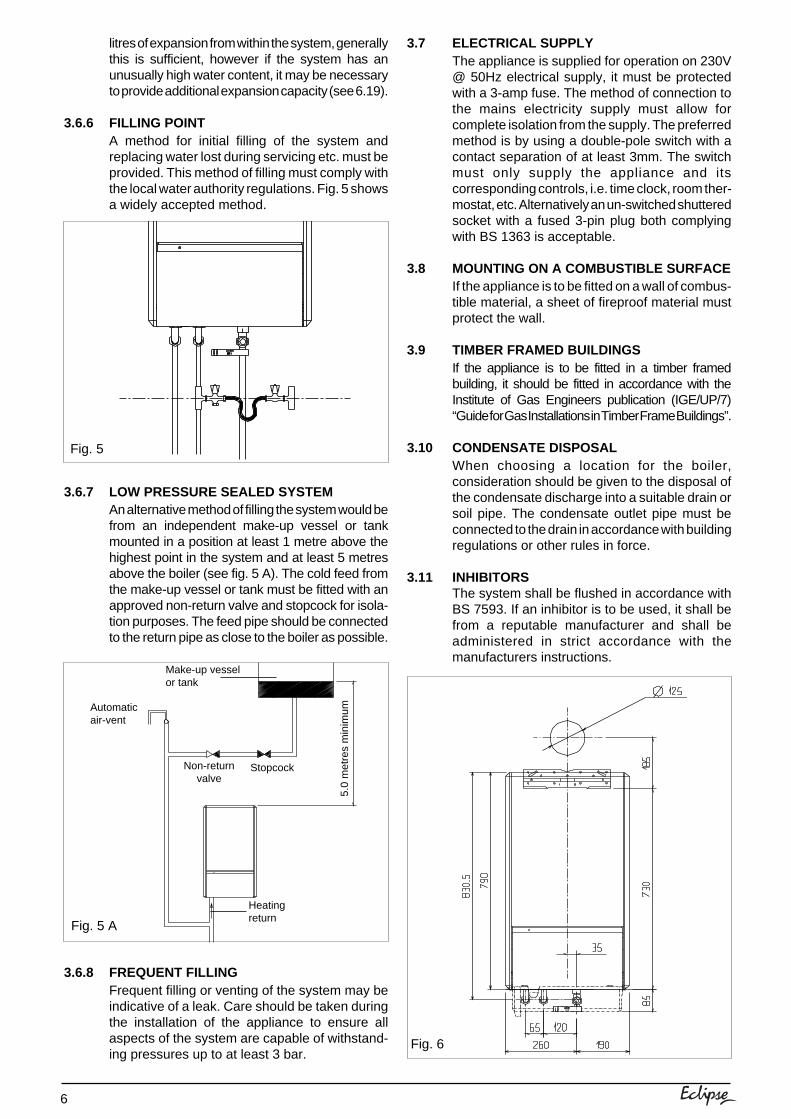
3.6.6 FILLING POINTA method for initial filling of the system andreplacing water lost during servicing etc. must beprovided. This method of filling must comply withthe local water authority regulations. Fig. 5 showsa widely accepted method.
3.6.7 LOW PRESSURE SEALED SYSTEMAn alternative method of filling the system would befrom an independent make-up vessel or tankmounted in a position at least 1 metre above thehighest point in the system and at least 5 metresabove the boiler (see fig. 5 A). The cold feed fromthe make-up vessel or tank must be fitted with anapproved non-return valve and stopcock for isola-tion purposes. The feed pipe should be connectedto the return pipe as close to the boiler as possible.
3.6.8 FREQUENT FILLINGFrequent filling or venting of the system may beindicative of a leak. Care should be taken duringthe installation of the appliance to ensure allaspects of the system are capable of withstand-ing pressures up to at least 3 bar.
Fig. 5
Fig. 5 A
Fig. 6
Make-up vesselor tank
Automaticair-vent
Non-returnvalve
Stopcock
5.0
met
res
min
imum
Heatingreturn
7
SECTION 4 INSTALLATION
4.1 DELIVERYThe appliance is delivered in a heavy-duty card-board carton. Lay the carton on the floor with thewriting the correct way up.
4.2 CONTENTSContained within the carton is:● the boiler;● the wall mounting bracket;● template;● an accessories pack containing the appliance
service valves and washers;● the instruction pack containing the installation
& servicing instructions, user instructions,Benchmark logbook, guarantee registrationcard, and a 3amp fuse.
4.3 UNPACKINGAt the top of the carton pull both sides open – donot use a knife – unfold the rest of the carton fromaround the appliance, carefully remove all pro-tective packaging from the appliance, and lay theaccessories etc. to one side.
4.4 PREPARATION FOR MOUNTING THEAPPLIANCEThe appliance should be mounted on a smooth,vertical, non-combustible surface, which must becapable of supporting the full weight of theappliance. Care should be exercised whendetermining the position of the appliance withrespect to hidden obstructions such as pipes,cables, etc.
When the position of the appliance has beendecided – using the template supplied – carefullymark the position of the wall-mounting bracket(see fig. 6) and flue-hole (if applicable).
4.5 FITTING THE FLUEThe top flue outlet permits both horizontal andvertical flue applications to be considered,alternatively, the Vokera twin flue system can beutilised if longer flue runs are required.
4.5.1 CONCENTRIC HORIZONTAL FLUE(For concentric vertical flue, see 4.5.2).(For twin flue applications, see 4.5.3).The appliance flue outlet elbow can be rotatedthrough 360° on its vertical axis. In addition theflue may be extended from the outlet elbow in thehorizontal plane (see 2.8). A reduction must alsobe made to the maximum length (see table below)when additional bends are used.
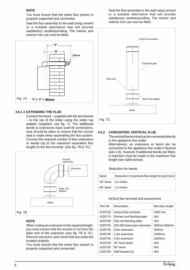
Using the template provided (see fig. 6), markand drill a 125mm hole for the passage of theflue pipe. The hole should have a 1° rise from theboiler to outside.
The fixing holes for the wall-mounting bracketshould now be drilled and plugged, anappropriate type and quantity of fixing should beused to ensure that the bracket is mountedsecurely. Once the bracket has been secured tothe wall, mount the appliance onto the bracket.
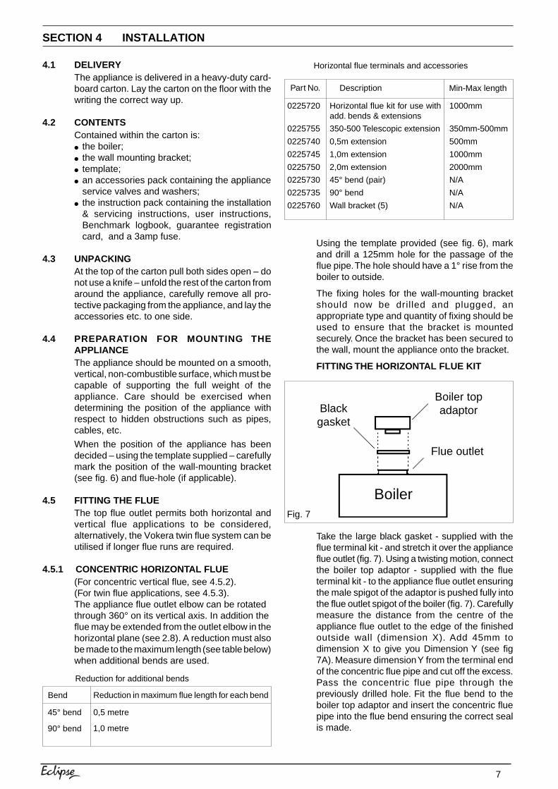
FITTING THE HORIZONTAL FLUE KIT
Take the large black gasket - supplied with theflue terminal kit - and stretch it over the applianceflue outlet (fig. 7). Using a twisting motion, connectthe boiler top adaptor - supplied with the flueterminal kit - to the appliance flue outlet ensuringthe male spigot of the adaptor is pushed fully intothe flue outlet spigot of the boiler (fig. 7). Carefullymeasure the distance from the centre of theappliance flue outlet to the edge of the finishedoutside wall (dimension X). Add 45mm todimension X to give you Dimension Y (see fig7A). Measure dimension Y from the terminal endof the concentric flue pipe and cut off the excess.Pass the concentric flue pipe through thepreviously drilled hole. Fit the flue bend to theboiler top adaptor and insert the concentric fluepipe into the flue bend ensuring the correct sealis made.
Reduction for additional bends
Bend Reduction in maximum flue length for each bend
45° bend
90° bend
0,5 metre
1,0 metre
Horizontal flue terminals and accessories
Part No. Description Min-Max length
0225720
0225755
0225740
0225745
0225750
0225730
0225735
0225760
Horizontal flue kit for use withadd. bends & extensions
350-500 Telescopic extension
0,5m extension
1,0m extension
2,0m extension
45° bend (pair)
90° bend
Wall bracket (5)
1000mm
350mm-500mm
500mm
1000mm
2000mm
N/A
N/A
N/A
Fig. 7
Blackgasket
Boiler
Flue outlet
Boiler topadaptor
8
4.5.2 CONCENTRIC VERTICAL FLUEThe vertical flue terminal can be connected directlyto the appliance flue outlet.Alternatively, an extension or bend can beconnected to the appliance flue outlet if desired(see 2.8), however if additional bends are fitted,a reduction must be made to the maximum fluelength (see table below).
NOTEYou must ensure that the entire flue system isproperly supported and connected.
Seal the flue assembly to the wall using cementor a suitable alternative that will providesatisfactory weatherproofing. The interior andexterior trim can now be fitted.
4.5.1.1 EXTENDING THE FLUEConnect the bend – supplied with the terminal kit– to the top of the boiler using the boiler topadapter (supplied, see fig. 7). The additionalbends & extensions have push-fit connections,care should be taken to ensure that the correctseal is made when assembling the flue system.Connect the required number of flue extensionsor bends (up to the maximum equivalent fluelength) to the flue terminal (see fig. 7B & 7C).
NOTEWhen cutting an extension to the required length,you must ensure that the excess is cut from theplain end of the extension (see fig. 7B & 7C).Remove any burrs, and check that any seals arelocated properly.You must ensure that the entire flue system isproperly supported and connected.
Fig. 7A
Fig. 7B
Seal the flue assembly to the wall using cementor a suitable alternative that will providesatisfactory weatherproofing. The interior andexterior trim can now be fitted.
Fig. 7C
Reduction in maximum flue length for each bend
Reduction for bends
Bend
45° bend
90° bend
0,5 metre
1,0 metre
Vertical flue terminal and accessories
Part No. Description Min-Max length
0225725
0225770
0225765
0225755
0225740
0225745
0225750
0225730
0225735
0225760
Vertical flue terminal
Pitched roof flashing plate
Flat roof flashing plate
350-500 telescopic extension
0,5m extension
1,0m extension
2,0m extension
45° bend (pair)
90° bend
Wall bracket (4)
1000 mm
N/A
N/A
350mm-500mm
500mm
1000mm
2000mm
N/A
N/A
N/A
Push-fitconnection
Extension
Boiler
Boiler topadaptor
Push-fit connection
Boiler
Extension pipe
Boiler top adaptor
Plain end

9
Using the dimensions given in fig. 8 as a reference,mark and cut a 105mm hole in the ceiling and/or roof.
IMPORTANTYou must ensure that the terminal is at least300mm from any structure or surface (see fig. 8).The vertical flue terminal is 1,0 metre in lengthand cannot be cut; therefore it may be necessaryto adjust the height of the appliance to suit or usea suitable extension.Encure that any horizontal sections of the flue systemhave a 1° fall back to the boiler (17mm per 1000mm).
Fit the appropriate flashing plate to the roof andinsert the vertical flue terminal through the flashingplate from the outside, ensuring that the collar onthe flue terminal fits over the flashing.
The fixing holes for the wall-mounting bracketshould now be drilled and plugged, an appropriatetype and quantity of fixing should be used toensure that the bracket is mounted securely.Once the bracket has been secured to the wall,mount the appliance onto the bracket.
NOTEWhen cutting an extension to the required length,you must ensure that the excess is cut from theplain end of the extension.Remove any burrs, and check that any seals arelocated properly.
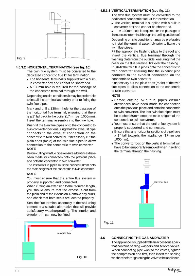
4.5.3 TWIN FLUE SYSTEMThe Vokera twin flue system enables greater fluedistances to be achieved (see 2.8) than that of thestandard concentric flue system. It can be used forhorizontal or vertical applications, however the twinflue system must be converted to the dedicatedconcentric flue kit for termination. It is essential thatthe installation of the twin flue system be carriedout in strict accordance with these instructions.
Fig. 8
GUIDANCE NOTES ON TWIN FLUEINSTALLATION● The flue must have a fall back of 1° back to the
appliance to allow any condensate that formsin the flue system to drain. Consideration mustalso be given to the fact that there is thepossibility of a small amount of condensatedripping from the terminal.
● Ensure that the entire flue system is adequatelysupported, use at least one bracket for eachextension.
● As the exhaust outlet pipe can reach very hightemperatures it must be protected to preventpersons touching the hot surface.
MOUNTING THE BOILERThe fixing holes for the wall-mounting bracketshould now be drilled and plugged, anappropriate type and quantity of fixing should beused to ensure that the bracket is mountedsecurely. Once the bracket has been secured tothe wall, mount the appliance onto the bracket.
4.5.3.1 INSTALLATION OF TWIN ADAPTOR KIT (seefig. 9)● Discard the restrictor ring (supplied with the twin
adapter kit).● Insert the exhaust connection manifold onto the
appliance flue outlet.● Place the silicone seal (supplied with twin
adapter kit) over the rim of the exhaustconnection manifold.
● Remove one of the blanking plate (located tothe left & right of the appliance flue outlet) and– using the same screws – install the air baffle.
Reduction in maximum flue length for each bend
Reduction for bends
Bend
45° bend
90° bend
1,0 metre
1,0 metre
Twin flue accessories
Part No. Description Length
0225805
0225810
359
0225770
0225765
0225815
0225820
0225825
0225830
0225835
0225840
0225845
0225850
0225855
Horizontal flue terminal
Vertical flue terminal
Twin adapter kit
Pitched roof flashing plate
Flat roof flashing plate
Condensate drain kit
0,25m extension (pair)
0,5m extension (pair)
1,0m extension (pair)
2,0m extension (pair)
45° bend (pair)
90° bend (pair)
Twin bracket (5)
Single bracket (5)
1000 mm
1000 mm
N/A
N/A
N/A
N/A
250mm
500mm
1000mm
2000mm
N/A
N/A
N/A
N/A
520mm
300mm minimum
520mm
10
4.5.3.2 HORIZONTAL TERMINATION (see fig. 10)The twin flue system must be converted to thededicated concentric flue kit for termination.● The horizontal terminal is supplied with a built-
in converter box and cannot be shortened.● A 130mm hole is required for the passage of
the concentric terminal through the wall.
Depending on site conditions it may be preferableto install the terminal assembly prior to fitting thetwin flue pipes.
Mark and drill a 130mm hole for the passage ofthe horizontal flue terminal, ensuring that thereis a 1° fall back to the boiler (17mm per 1000mm).Insert the terminal assembly into the flue hole.
Push-fit the twin flue pipes onto the concentric totwin converter box ensuring that the exhaust pipeconnects to the exhaust connection on theconcentric to twin converter. If necessary cut theplain ends (male) of the twin flue pipes to allowconnection to the concentric to twin converter.NOTEBefore cutting twin flue pipes ensure allowances havebeen made for connection onto the previous pieceand onto the concentric to twin converter.The last twin flue pipes must be pushed 50mm ontothe male spigots of the concentric to twin converter.
NOTEYou must ensure that the entire flue system isproperly supported and connected.When cutting an extension to the required length,you should ensure that the excess is cut fromthe plain end of the extension. Remove any burrs,and check that both seals are located properly.
Seal the flue terminal assembly to the wall usingcement or a suitable alternative that will providesatisfactory weatherproofing. The interior andexterior trim can now be fitted.
Fig. 9
Fig. 10
4.5.3.3 VERTICAL TERMINATION (see fig. 11)The twin flue system must be converted to thededicated concentric flue kit for termination.● The vertical terminal is supplied with a built-in
converter box and cannot be shortened.● A 130mm hole is required for the passage ofthe concentric terminal through the ceiling and/or roof.
Depending on site conditions it may be preferableto install the terminal assembly prior to fitting thetwin flue pipes.Fit the appropriate flashing plate to the roof andinsert the vertical flue terminal through theflashing plate from the outside, ensuring that thecollar on the flue terminal fits over the flashing.Push-fit the twin flue pipes onto the concentric totwin converter ensuring that the exhaust pipeconnects to the exhaust connection on theconcentric to twin converter.If necessary cut the plain ends (male) of the twinflue pipes to allow connection to the concentricto twin converter.
NOTE● Before cutting twin flue pipes ensure
allowances have been made for connectiononto the previous piece and onto the concentricto twin converter. The last twin flue pipes mustbe pushed 50mm onto the male spigots of theconcentric to twin converter.
● You must ensure that the entire flue system isproperly supported and connected.
● Ensure that any horizontal sections of pipe havea 1° fall towards the appliance (17mm per1000mm).
● The convertor box on the vertical terminal willhave to be temporarily removed when insertingthe terminal through the flashing.
4.6 CONNECTING THE GAS AND WATERThe appliance is supplied with an accessories packthat contains sealing washers and service valves.When connecting pipe work to the valves, tightenthe compression end first, then insert the sealingwashers before tightening the valve to the appliance.
Fig. 11
convertor box
convertor box
11
NOTE
It will be necessary to hold the valve with onespanner whilst tightening with another.
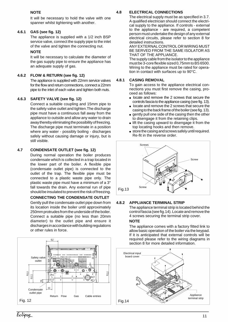
4.6.1 GAS (see fig. 12)The appliance is supplied with a 1/2 inch BSPservice valve, connect the supply pipe to the inletof the valve and tighten the connecting nut.
NOTEIt will be necessary to calculate the diameter ofthe gas supply pipe to ensure the appliance hasan adequate supply of gas.
4.6.2 FLOW & RETURN (see fig. 12)The appliance is supplied with 22mm service valvesfor the flow and return connections, connect a 22mmpipe to the inlet of each valve and tighten both nuts.
4.6.3 SAFETY VALVE (see fig. 12)Connect a suitable coupling and 15mm pipe tothe safety valve outlet and tighten.The dischargepipe must have a continuous fall away from theappliance to outside and allow any water to drainaway thereby eliminating the possibility of freezing.The discharge pipe must terminate in a positionwhere any water - possibly boiling - dischargessafely without causing damage or injury, but isstill visible.
4.7 CONDENSATE OUTLET (see fig. 12)During normal operation the boiler producescondensate which is collected in a trap located inthe lower part of the boiler. A flexible pipe(condensate outlet pipe) is connected to theoutlet of the trap. The flexible pipe must beconnected to a plastic waste pipe only. Theplastic waste pipe must have a minimum of a 3°fall towards the drain. Any external run of pipeshould be insulated to prevent the risk of freezing.
CONNECTING THE CONDENSATE OUTLETGently pull the condensate outlet pipe down fromits location inside the boiler until approximately250mm protrudes from the underside of the boiler.Connect a suitable pipe (no less than 20mmdiameter) to the outlet pipe and ensure itdischarges in accordance with building regulationsor other rules in force.
Fig. 12
4.8 ELECTRICAL CONNECTIONSThe electrical supply must be as specified in 3.7.A qualified electrician should connect the electri-cal supply to the appliance. If controls - externalto the appliance - are required, a competentperson must undertake the design of any externalelectrical circuits, please refer to section 8 fordetailed instructions.ANY EXTERNAL CONTROL OR WIRING MUSTBE SERVED FROM THE SAME ISOLATOR ASTHAT OF THE APPLIANCE.The supply cable from the isolator to the appliancemust be 3-core flexible sized 0,75mm to BS 6500.Wiring to the appliance must be rated for opera-tion in contact with surfaces up to 90°C.
4.8.1 CASING REMOVALTo gain access to the appliance electrical con-nections you must first remove the casing, pro-ceed as follows:● locate and remove the 2 screws that secure the
controls fascia to the appliance casing (see fig. 13).● locate and remove the 2 screws that secure the
casing to the back frame of the boiler (see fig. 13).● gently pull one side of the casing then the other
to disengage it from the retaining clips.● lift the casing upward to disengage it from the
top locating hooks and then remove.● store the casing and screws safely until required.
Re-fit in the reverse order.
4.8.2 APPLIANCE TERMINAL STRIPThe appliance terminal strip is located behind thecontrol fascia (see fig.14). Locate and remove the4 screws securing the terminal strip cover.NOTEThe appliance comes with a factory fitted link toallow basic operation of the boiler via the keypad.If it is anticipated that external controls will berequired please refer to the wiring diagrams insection 8 for more detailed information.
Fig.13
Fig.14
Safety valveoutlet
Condensateoutlet pipe
Return Flow Gas Cable entries
Electrical inputboard cover
Applianceterminal strip
Screws
Screw
Screw
12
5.1 GAS SUPPLY INSTALLATIONInspect the entire installation including the gasmeter, test for soundness and purge. Refer to BS6891 for specific instruction.
5.2 THE HEATING SYSTEMThe appliance contains components that maybecome damaged or rendered inoperable by oilsand/or debris that are residual from the installa-tion of the system, consequently it is essentialthat the system be flushed in accordance with thefollowing instructions.
5.3 INITIAL FILLING OF THE SYSTEMEnsure both flow & return service valves areopen, remove appliance casing as described in4.8.1, identify the automatic air release valve andloosen the dust cap by turning cap anti-clockwiseone full turn. IMPORTANT, THERE ARE NOMANUAL AIR RELEASE VALVES LOCATEDON THE APPLIANCE. Ensure all manual airrelease valves located on the heating system areclosed. Using the method of filling as described infig. 5, slowly proceed to fill the system. As waterenters the system the pressure gauge will beginto rise. Once the gauge has reached 1bar closethe filling valve and begin venting all manual airrelease valves, starting at the lowest first. It maybe necessary to go back and top-up the pressureuntil the entire system has been filled. Inspect thesystem for water soundness, rectifying any leaks.
5.4 INITIAL FLUSHING OF THE SYSTEMThe whole of the heating system must be flushed bothcold and hot as detailed in 5.7. Open all radiator orheating valves and the appliance flow & return servicevalves. Drain the boiler and system from the lowestpoints. Open the drain valve full bore to remove anyinstallation debris from the boiler prior to lighting. Refillthe boiler and heating system as described in 5.3.
Fig. 15
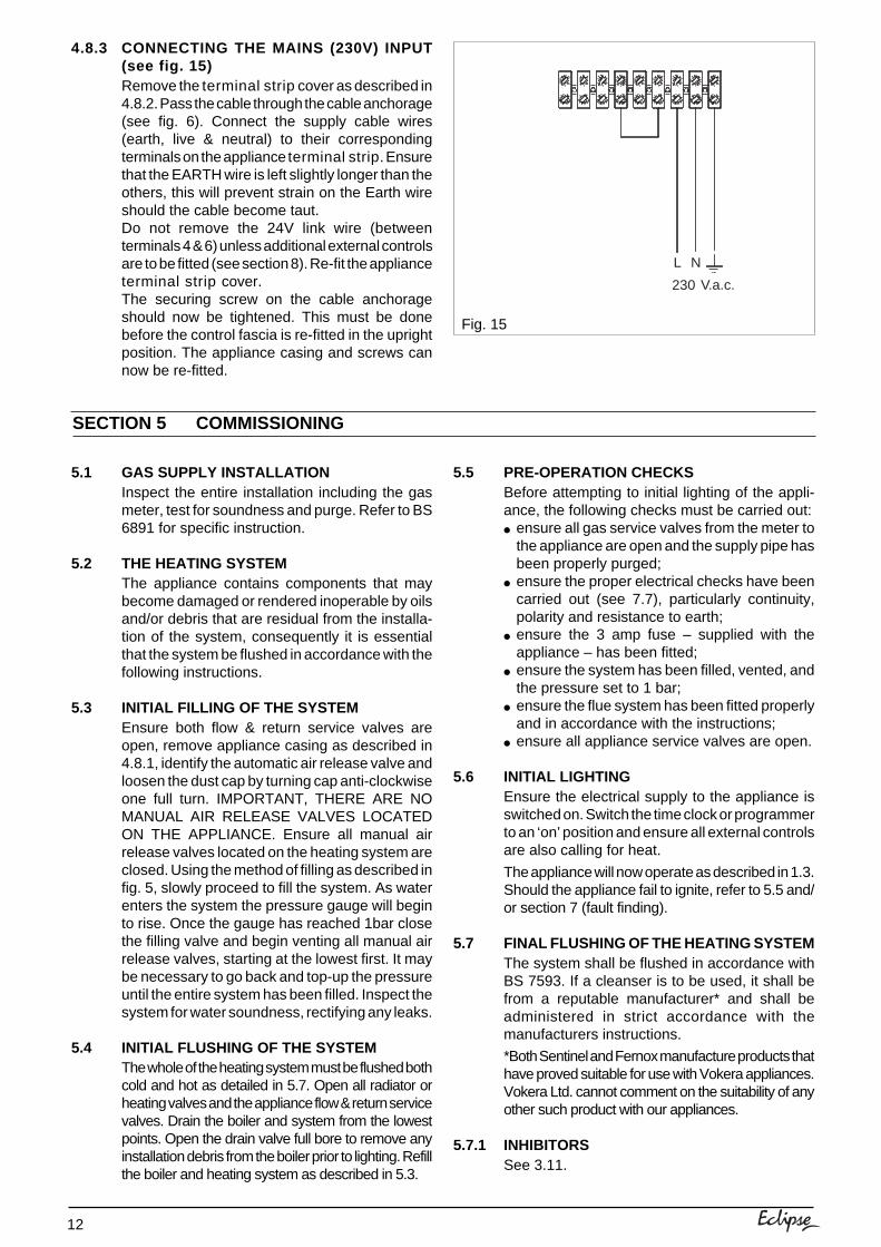
4.8.3 CONNECTING THE MAINS (230V) INPUT(see fig. 15)Remove the terminal strip cover as described in4.8.2. Pass the cable through the cable anchorage(see fig. 6). Connect the supply cable wires(earth, live & neutral) to their correspondingterminals on the appliance terminal strip. Ensurethat the EARTH wire is left slightly longer than theothers, this will prevent strain on the Earth wireshould the cable become taut.Do not remove the 24V link wire (betweenterminals 4 & 6) unless additional external controlsare to be fitted (see section 8). Re-fit the applianceterminal strip cover.The securing screw on the cable anchorageshould now be tightened. This must be donebefore the control fascia is re-fitted in the uprightposition. The appliance casing and screws cannow be re-fitted.
SECTION 5 COMMISSIONING
5.5 PRE-OPERATION CHECKSBefore attempting to initial lighting of the appli-ance, the following checks must be carried out:● ensure all gas service valves from the meter to
the appliance are open and the supply pipe hasbeen properly purged;
● ensure the proper electrical checks have beencarried out (see 7.7), particularly continuity,polarity and resistance to earth;
● ensure the 3 amp fuse – supplied with theappliance – has been fitted;
● ensure the system has been filled, vented, andthe pressure set to 1 bar;
● ensure the flue system has been fitted properlyand in accordance with the instructions;
● ensure all appliance service valves are open.
5.6 INITIAL LIGHTINGEnsure the electrical supply to the appliance isswitched on. Switch the time clock or programmerto an ‘on’ position and ensure all external controlsare also calling for heat.
The appliance will now operate as described in 1.3.Should the appliance fail to ignite, refer to 5.5 and/or section 7 (fault finding).
5.7 FINAL FLUSHING OF THE HEATING SYSTEMThe system shall be flushed in accordance withBS 7593. If a cleanser is to be used, it shall befrom a reputable manufacturer* and shall beadministered in strict accordance with themanufacturers instructions.
*Both Sentinel and Fernox manufacture products thathave proved suitable for use with Vokera appliances.Vokera Ltd. cannot comment on the suitability of anyother such product with our appliances.
5.7.1 INHIBITORSSee 3.11.
L N
230 V.a.c.
13
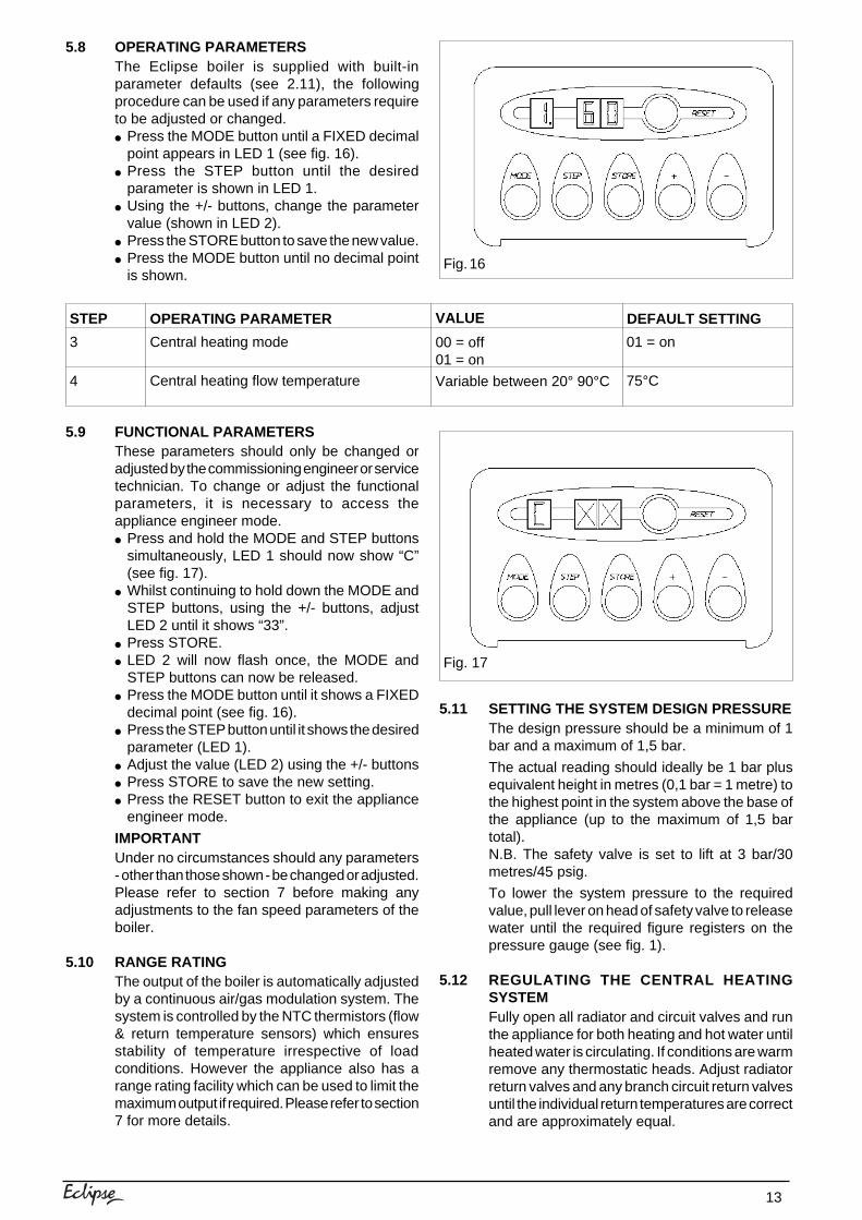
5.8 OPERATING PARAMETERSThe Eclipse boiler is supplied with built-inparameter defaults (see 2.11), the followingprocedure can be used if any parameters requireto be adjusted or changed.● Press the MODE button until a FIXED decimal
point appears in LED 1 (see fig. 16).● Press the STEP button until the desired
parameter is shown in LED 1.● Using the +/- buttons, change the parameter
value (shown in LED 2).● Press the STORE button to save the new value.● Press the MODE button until no decimal point
is shown.
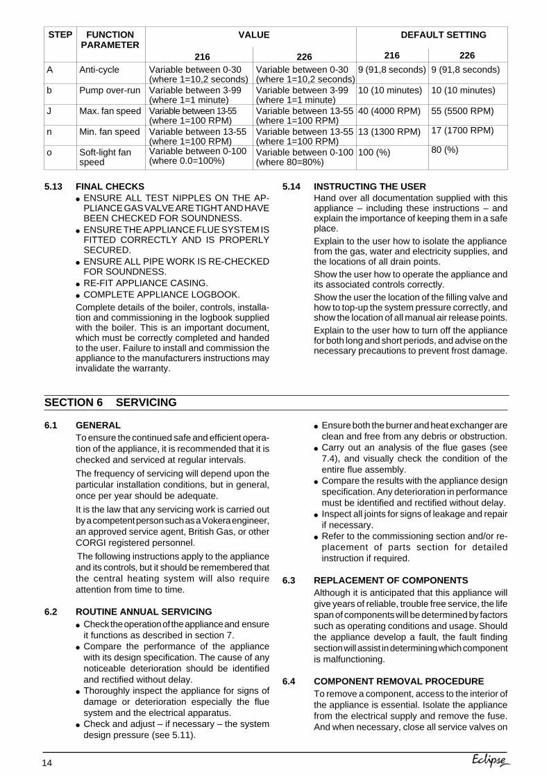
5.9 FUNCTIONAL PARAMETERSThese parameters should only be changed oradjusted by the commissioning engineer or servicetechnician. To change or adjust the functionalparameters, it is necessary to access theappliance engineer mode.● Press and hold the MODE and STEP buttons
simultaneously, LED 1 should now show “C”(see fig. 17).
● Whilst continuing to hold down the MODE andSTEP buttons, using the +/- buttons, adjustLED 2 until it shows “33”.
● Press STORE.● LED 2 will now flash once, the MODE and
STEP buttons can now be released.● Press the MODE button until it shows a FIXED
decimal point (see fig. 16).● Press the STEP button until it shows the desired
parameter (LED 1).● Adjust the value (LED 2) using the +/- buttons● Press STORE to save the new setting.● Press the RESET button to exit the appliance
engineer mode.
IMPORTANTUnder no circumstances should any parameters- other than those shown - be changed or adjusted.Please refer to section 7 before making anyadjustments to the fan speed parameters of theboiler.
5.10 RANGE RATINGThe output of the boiler is automatically adjustedby a continuous air/gas modulation system. Thesystem is controlled by the NTC thermistors (flow& return temperature sensors) which ensuresstability of temperature irrespective of loadconditions. However the appliance also has arange rating facility which can be used to limit themaximum output if required. Please refer to section7 for more details.
STEP OPERATING PARAMETER
3
4
VALUE DEFAULT SETTING
00 = off01 = on
Variable between 20° 90°C
01 = on
75°C
Central heating mode
Central heating flow temperature
Fig. 17
5.11 SETTING THE SYSTEM DESIGN PRESSUREThe design pressure should be a minimum of 1bar and a maximum of 1,5 bar.
The actual reading should ideally be 1 bar plusequivalent height in metres (0,1 bar = 1 metre) tothe highest point in the system above the base ofthe appliance (up to the maximum of 1,5 bartotal).N.B. The safety valve is set to lift at 3 bar/30metres/45 psig.
To lower the system pressure to the requiredvalue, pull lever on head of safety valve to releasewater until the required figure registers on thepressure gauge (see fig. 1).
5.12 REGULATING THE CENTRAL HEATINGSYSTEMFully open all radiator and circuit valves and runthe appliance for both heating and hot water untilheated water is circulating. If conditions are warmremove any thermostatic heads. Adjust radiatorreturn valves and any branch circuit return valvesuntil the individual return temperatures are correctand are approximately equal.
Fig. 16
14
6.1 GENERALTo ensure the continued safe and efficient opera-tion of the appliance, it is recommended that it ischecked and serviced at regular intervals.
The frequency of servicing will depend upon theparticular installation conditions, but in general,once per year should be adequate.
It is the law that any servicing work is carried outby a competent person such as a Vokera engineer,an approved service agent, British Gas, or otherCORGI registered personnel.
The following instructions apply to the applianceand its controls, but it should be remembered thatthe central heating system will also requireattention from time to time.
6.2 ROUTINE ANNUAL SERVICING● Check the operation of the appliance and ensure
it functions as described in section 7.● Compare the performance of the appliance
with its design specification. The cause of anynoticeable deterioration should be identifiedand rectified without delay.
● Thoroughly inspect the appliance for signs ofdamage or deterioration especially the fluesystem and the electrical apparatus.
● Check and adjust – if necessary – the systemdesign pressure (see 5.11).
● Ensure both the burner and heat exchanger areclean and free from any debris or obstruction.
● Carry out an analysis of the flue gases (see7.4), and visually check the condition of theentire flue assembly.
● Compare the results with the appliance designspecification. Any deterioration in performancemust be identified and rectified without delay.
● Inspect all joints for signs of leakage and repairif necessary.
● Refer to the commissioning section and/or re-placement of parts section for detailedinstruction if required.
6.3 REPLACEMENT OF COMPONENTSAlthough it is anticipated that this appliance willgive years of reliable, trouble free service, the lifespan of components will be determined by factorssuch as operating conditions and usage. Shouldthe appliance develop a fault, the fault findingsection will assist in determining which componentis malfunctioning.
6.4 COMPONENT REMOVAL PROCEDURETo remove a component, access to the interior ofthe appliance is essential. Isolate the appliancefrom the electrical supply and remove the fuse.And when necessary, close all service valves on
5.13 FINAL CHECKS● ENSURE ALL TEST NIPPLES ON THE AP-
PLIANCE GAS VALVE ARE TIGHT AND HAVEBEEN CHECKED FOR SOUNDNESS.
● ENSURE THE APPLIANCE FLUE SYSTEM ISFITTED CORRECTLY AND IS PROPERLYSECURED.
● ENSURE ALL PIPE WORK IS RE-CHECKEDFOR SOUNDNESS.
● RE-FIT APPLIANCE CASING.● COMPLETE APPLIANCE LOGBOOK.Complete details of the boiler, controls, installa-tion and commissioning in the logbook suppliedwith the boiler. This is an important document,which must be correctly completed and handedto the user. Failure to install and commission theappliance to the manufacturers instructions mayinvalidate the warranty.
STEP FUNCTIONPARAMETER
VALUE DEFAULT SETTING
216 226 226216
A
b
J
n
o
Variable between 0-30(where 1=10,2 seconds)Variable between 3-99(where 1=1 minute)Variable between 13-55(where 1=100 RPM)Variable between 13-55(where 1=100 RPM)Variable between 0-100(where 80=80%)
Variable between 0-30(where 1=10,2 seconds)Variable between 3-99(where 1=1 minute)Variable between 13-55(where 1=100 RPM)Variable between 13-55(where 1=100 RPM)Variable between 0-100(where 0.0=100%)
9 (91,8 seconds)
10 (10 minutes)
40 (4000 RPM)
13 (1300 RPM)
100 (%)
9 (91,8 seconds)
10 (10 minutes)
55 (5500 RPM)
17 (1700 RPM)
80 (%)
Anti-cycle
Pump over-run
Max. fan speed
Min. fan speed
Soft-light fanspeed
5.14 INSTRUCTING THE USERHand over all documentation supplied with thisappliance – including these instructions – andexplain the importance of keeping them in a safeplace.Explain to the user how to isolate the appliancefrom the gas, water and electricity supplies, andthe locations of all drain points.Show the user how to operate the appliance andits associated controls correctly.Show the user the location of the filling valve andhow to top-up the system pressure correctly, andshow the location of all manual air release points.Explain to the user how to turn off the appliancefor both long and short periods, and advise on thenecessary precautions to prevent frost damage.
SECTION 6 SERVICING
15
the appliance, remove the appliance casing asdescribed in section 4.8.1. Drain the water contentfrom the appliance via the safety valve. Ensuresome water absorbent cloths are available tocatch any residual water that may drip from theappliance or removed component. Undertake acomplete commissioning check as detailed insection 5, after replacing any component.ALWAYS TEST FOR GAS SOUNDNESS IFANY GAS CARRYING COMPONENTS HAVEBEEN REMOVED OR DISTURBED.
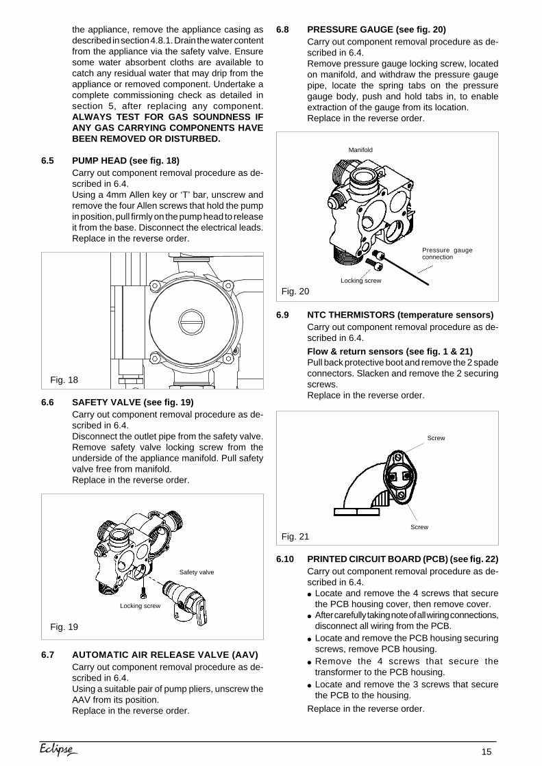
6.5 PUMP HEAD (see fig. 18)Carry out component removal procedure as de-scribed in 6.4.Using a 4mm Allen key or ‘T’ bar, unscrew andremove the four Allen screws that hold the pumpin position, pull firmly on the pump head to releaseit from the base. Disconnect the electrical leads.Replace in the reverse order.
6.6 SAFETY VALVE (see fig. 19)Carry out component removal procedure as de-scribed in 6.4.Disconnect the outlet pipe from the safety valve.Remove safety valve locking screw from theunderside of the appliance manifold. Pull safetyvalve free from manifold.Replace in the reverse order.
6.7 AUTOMATIC AIR RELEASE VALVE (AAV)Carry out component removal procedure as de-scribed in 6.4.Using a suitable pair of pump pliers, unscrew theAAV from its position.Replace in the reverse order.
Fig. 18
Fig. 19
6.8 PRESSURE GAUGE (see fig. 20)Carry out component removal procedure as de-scribed in 6.4.Remove pressure gauge locking screw, locatedon manifold, and withdraw the pressure gaugepipe, locate the spring tabs on the pressuregauge body, push and hold tabs in, to enableextraction of the gauge from its location.Replace in the reverse order.
6.9 NTC THERMISTORS (temperature sensors)Carry out component removal procedure as de-scribed in 6.4.
Flow & return sensors (see fig. 1 & 21)Pull back protective boot and remove the 2 spadeconnectors. Slacken and remove the 2 securingscrews.Replace in the reverse order.
6.10 PRINTED CIRCUIT BOARD (PCB) (see fig. 22)Carry out component removal procedure as de-scribed in 6.4.● Locate and remove the 4 screws that secure
the PCB housing cover, then remove cover.● After carefully taking note of all wiring connections,
disconnect all wiring from the PCB.● Locate and remove the PCB housing securing
screws, remove PCB housing.● Remove the 4 screws that secure the
transformer to the PCB housing.● Locate and remove the 3 screws that secure
the PCB to the housing.
Replace in the reverse order.
Fig. 20
Fig. 21
Pressure gaugeconnection
Locking screw
Manifold
Locking screw
Safety valve
Screw
Screw
16
Fig. 25
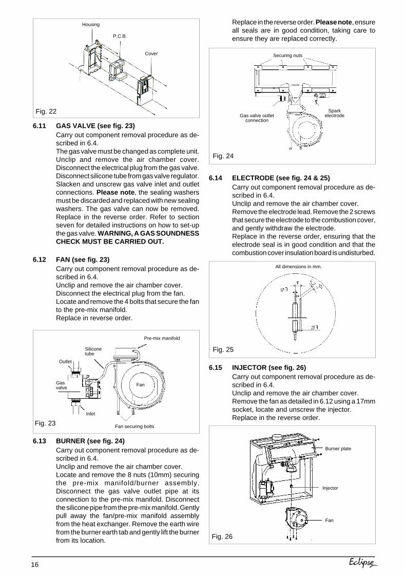
6.11 GAS VALVE (see fig. 23)Carry out component removal procedure as de-scribed in 6.4.The gas valve must be changed as complete unit.Unclip and remove the air chamber cover.Disconnect the electrical plug from the gas valve.Disconnect silicone tube from gas valve regulator.Slacken and unscrew gas valve inlet and outletconnections. Please note , the sealing washersmust be discarded and replaced with new sealingwashers. The gas valve can now be removed.Replace in the reverse order. Refer to sectionseven for detailed instructions on how to set-upthe gas valve. WARNING, A GAS SOUNDNESSCHECK MUST BE CARRIED OUT.
6.12 FAN (see fig. 23)Carry out component removal procedure as de-scribed in 6.4.Unclip and remove the air chamber cover.Disconnect the electrical plug from the fan.Locate and remove the 4 bolts that secure the fanto the pre-mix manifold.Replace in reverse order.
6.13 BURNER (see fig. 24)Carry out component removal procedure as de-scribed in 6.4.Unclip and remove the air chamber cover.Locate and remove the 8 nuts (10mm) securingthe pre-mix manifold/burner assembly.Disconnect the gas valve outlet pipe at itsconnection to the pre-mix manifold. Disconnectthe silicone pipe from the pre-mix manifold. Gentlypull away the fan/pre-mix manifold assemblyfrom the heat exchanger. Remove the earth wirefrom the burner earth tab and gently lift the burnerfrom its location.
Replace in the reverse order. Please note , ensureall seals are in good condition, taking care toensure they are replaced correctly.
6.14 ELECTRODE (see fig. 24 & 25)Carry out component removal procedure as de-scribed in 6.4.Unclip and remove the air chamber cover.Remove the electrode lead. Remove the 2 screwsthat secure the electrode to the combustion cover,and gently withdraw the electrode.Replace in the reverse order, ensuring that theelectrode seal is in good condition and that thecombustion cover insulation board is undisturbed.
6.15 INJECTOR (see fig. 26)Carry out component removal procedure as de-scribed in 6.4.Unclip and remove the air chamber cover.Remove the fan as detailed in 6.12 using a 17mmsocket, locate and unscrew the injector.Replace in the reverse order.
Fig. 22
Fig. 24
Fig. 26
Housing
P.C.B.
Cover
Gasvalve
Siliconetube
Outlet
Inlet
Pre-mix manifold
Fan securing boltsFig. 23
Fan
Securing nuts
SparkelectrodeGas valve outlet
connection
All dimensions in mm.
Injector
Fan
Burner plate
17
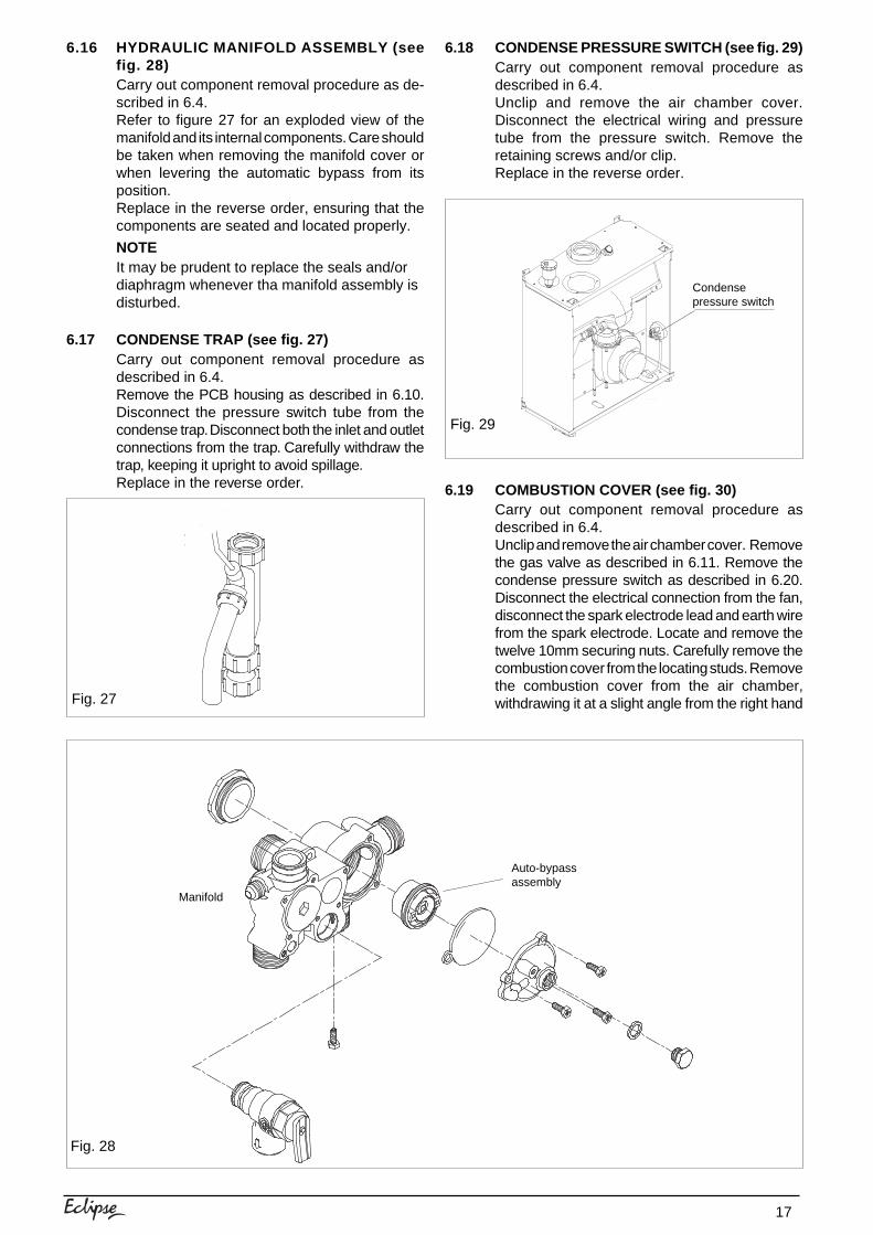
6.16 HYDRAULIC MANIFOLD ASSEMBLY (seefig. 28)Carry out component removal procedure as de-scribed in 6.4.Refer to figure 27 for an exploded view of themanifold and its internal components. Care shouldbe taken when removing the manifold cover orwhen levering the automatic bypass from itsposition.Replace in the reverse order, ensuring that thecomponents are seated and located properly.
NOTEIt may be prudent to replace the seals and/ordiaphragm whenever tha manifold assembly isdisturbed.
6.17 CONDENSE TRAP (see fig. 27)Carry out component removal procedure asdescribed in 6.4.Remove the PCB housing as described in 6.10.Disconnect the pressure switch tube from thecondense trap. Disconnect both the inlet and outletconnections from the trap. Carefully withdraw thetrap, keeping it upright to avoid spillage.Replace in the reverse order.
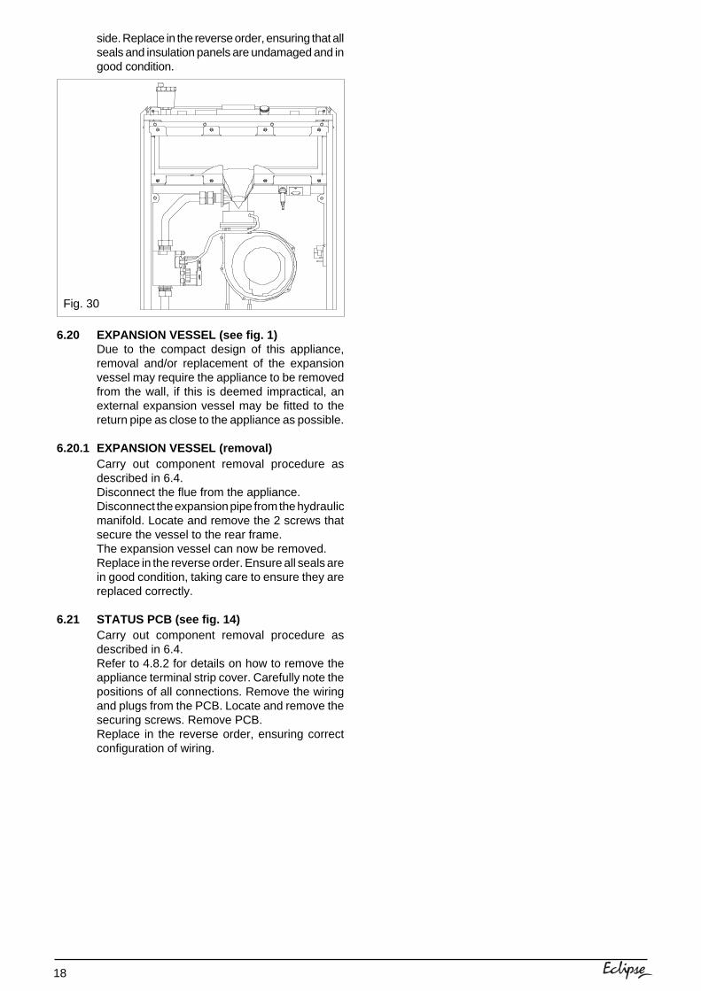
6.18 CONDENSE PRESSURE SWITCH (see fig. 29)Carry out component removal procedure asdescribed in 6.4.Unclip and remove the air chamber cover.Disconnect the electrical wiring and pressuretube from the pressure switch. Remove theretaining screws and/or clip.Replace in the reverse order.
6.19 COMBUSTION COVER (see fig. 30)Carry out component removal procedure asdescribed in 6.4.Unclip and remove the air chamber cover. Removethe gas valve as described in 6.11. Remove thecondense pressure switch as described in 6.20.Disconnect the electrical connection from the fan,disconnect the spark electrode lead and earth wirefrom the spark electrode. Locate and remove thetwelve 10mm securing nuts. Carefully remove thecombustion cover from the locating studs. Removethe combustion cover from the air chamber,withdrawing it at a slight angle from the right handFig. 27
Fig. 29
Condensepressure switch
Fig. 28
Auto-bypassassembly
Manifold
18
side. Replace in the reverse order, ensuring that allseals and insulation panels are undamaged and ingood condition.
6.20 EXPANSION VESSEL (see fig. 1)Due to the compact design of this appliance,removal and/or replacement of the expansionvessel may require the appliance to be removedfrom the wall, if this is deemed impractical, anexternal expansion vessel may be fitted to thereturn pipe as close to the appliance as possible.
6.20.1 EXPANSION VESSEL (removal)Carry out component removal procedure asdescribed in 6.4.Disconnect the flue from the appliance.Disconnect the expansion pipe from the hydraulicmanifold. Locate and remove the 2 screws thatsecure the vessel to the rear frame.The expansion vessel can now be removed.Replace in the reverse order. Ensure all seals arein good condition, taking care to ensure they arereplaced correctly.
6.21 STATUS PCB (see fig. 14)Carry out component removal procedure asdescribed in 6.4.Refer to 4.8.2 for details on how to remove theappliance terminal strip cover. Carefully note thepositions of all connections. Remove the wiringand plugs from the PCB. Locate and remove thesecuring screws. Remove PCB.Replace in the reverse order, ensuring correctconfiguration of wiring.
Fig. 30
19
7.1 CHECKING APPLIANCE OPERATIONWhen carrying out any repairs or servicing to theappliance, the relevant commissioning and/orset-up procedure must be undertaken to ensurethe continued safe operation of the appliance.Particular attention should be made to ensuregas soundness, water soundness, and theelectrical integrity of the appliance.
7.2 APPLIANCE MODE OF OPERATION
7.2.1 START-UPWhen power is first supplied to the appliance itwill go through a self-purge procedure wherebythe pump & fan will be momentarily energised.The boiler will then operate in either one of thefollowing modes:● At rest● Heating and/or Hot Water request
7.2.2 AT RESTWhen there is no demand for heating or hot waterand the appliance remains inactive for a period of24 hours, the pump will be energised for a fewmoments to prevent it from seizing. Should theflow temperature sensor fall below 7°C the pumpwill be energised. If the flow sensor temperaturefalls to below 3°C the burner will be lit and theappliance will operate at the minimum output untilthe temperature of the flow sensor reaches 10°C,whereupon the pump will continue to run in pumpover-run mode.
7.2.3 MODE OF OPERATION (heating/hot waterrequest)When there is a request for heat via theprogremmer and/or external controls, the pumpand fan will be activated via the flow temperaturesensor. When the fan is sensed to be operatingcorrectly, the ignition sequence commences. Thespeed of the fan and therefore the output of theboiler is determined by the temperature of thewater sensed by the flow & return temperaturesensors, consequently a high temperature at theflow sensor results in a lower fan speed. As thewater temperature increases, the temperaturesensors – located on the flow & return pipes of theboiler – reduce the fan speed via the electroniccircuitry. Depending on the load, either the watertemperature will continue to rise until the set pointis achieved or the water temperature will fallwhereby fan speed will increase relative to theoutput required. When the boiler has reached theset point, the burner will switch off. The built-inanti-cycle device prevents the burner from re-lighting for an adjustable period of time (factorydefault is 3 minutes). When the temperature ofthe flow sensor falls below the set-point, theburner will re-light.
SECTION 7 CHECKS, ADJUSTMENTS, AND FAULT FINDING
7.3 CHECKING/ADJUSTING FAN SPEEDTo check the fan speeds, you must first accessthe engineer mode. The fan speed should only bechanged or adjusted by the commissioningengineer or service technician (see 5.9).To access the appliance engineer mode:● press and hold the MODE and STEP buttons
simultaneously, LED 1 should now show ‘C’(see fig. 17).
● whilst continuing to hold down the MODE andSTEP buttons, using the +/- buttons, adjustLED 2 until it shows ‘33’.
● press STORE● LED 2 will now flash twice, the MODE and
STEP buttons can now be released● press the MODE button until it shows a FIXED
decimal point (see fig. 16).
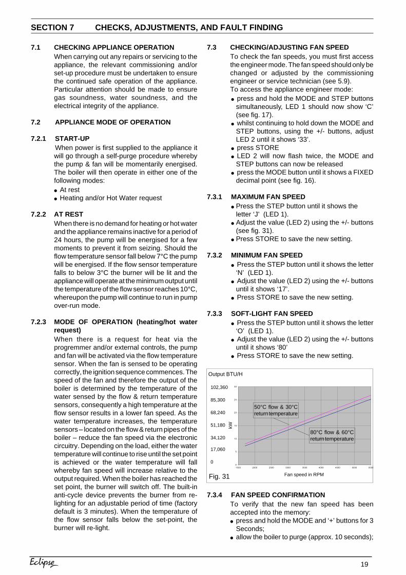
7.3.1 MAXIMUM FAN SPEED● Press the STEP button until it shows the
letter ‘J’ (LED 1).● Adjust the value (LED 2) using the +/- buttons
(see fig. 31).● Press STORE to save the new setting.
7.3.2 MINIMUM FAN SPEED● Press the STEP button until it shows the letter
‘N’ (LED 1).● Adjust the value (LED 2) using the +/- buttons
until it shows ‘17’.● Press STORE to save the new setting.
7.3.3 SOFT-LIGHT FAN SPEED● Press the STEP button until it shows the letter
‘O’ (LED 1).● Adjust the value (LED 2) using the +/- buttons
until it shows ‘80’● Press STORE to save the new setting.
7.3.4 FAN SPEED CONFIRMATIONTo verify that the new fan speed has beenaccepted into the memory:● press and hold the MODE and ‘+’ buttons for 3
Seconds;● allow the boiler to purge (approx. 10 seconds);
Fig. 31
0
5
10
15
20
25
30
1500 2000 2500 3000 3500 4000 4500 5000 5500
Fan speed in RPM
kW
Output BTU/H
102,360
68,240
17,060
0
51,180
34,120
85,300
50°C flow & 30°Creturn temperature
80°C flow & 60°Creturn temperature
20
● when ‘H’ is displayed in LED 1, press theMODE button until LED 1 shows an alternatingcursor (see fig. 32);
● when the digit is to the left, LED 2 shows the firsttwo digits of the maximum fan speed;
● when the digit is to the right, LED 2 shows thelast two digits of the maximum fan speed;
● press the MODE button until a fixed decimal isshown in LED 1;
● press and hold the MODE and ‘-–‘ buttons until‘L’ appears in LED 1;
● press the MODE button until LED 1 shows analternating cursor (see fig. 32);
● when the digit is to the left, LED 2 shows the firsttwo digits of the minimum fan speed;
● when the digit is to the right, LED 2 shows thelast two digits of the minimum fan speed.
NOTEThe actual fan speed displayed may not exactlymatch what has been programmed. However,providing the displayed speed is within 200 RPM(+/-) of the programmed speed, this is acceptable.
7.3.5 EXIT ENGINEER MODEPress the RESET button to exit the applianceengineer mode.
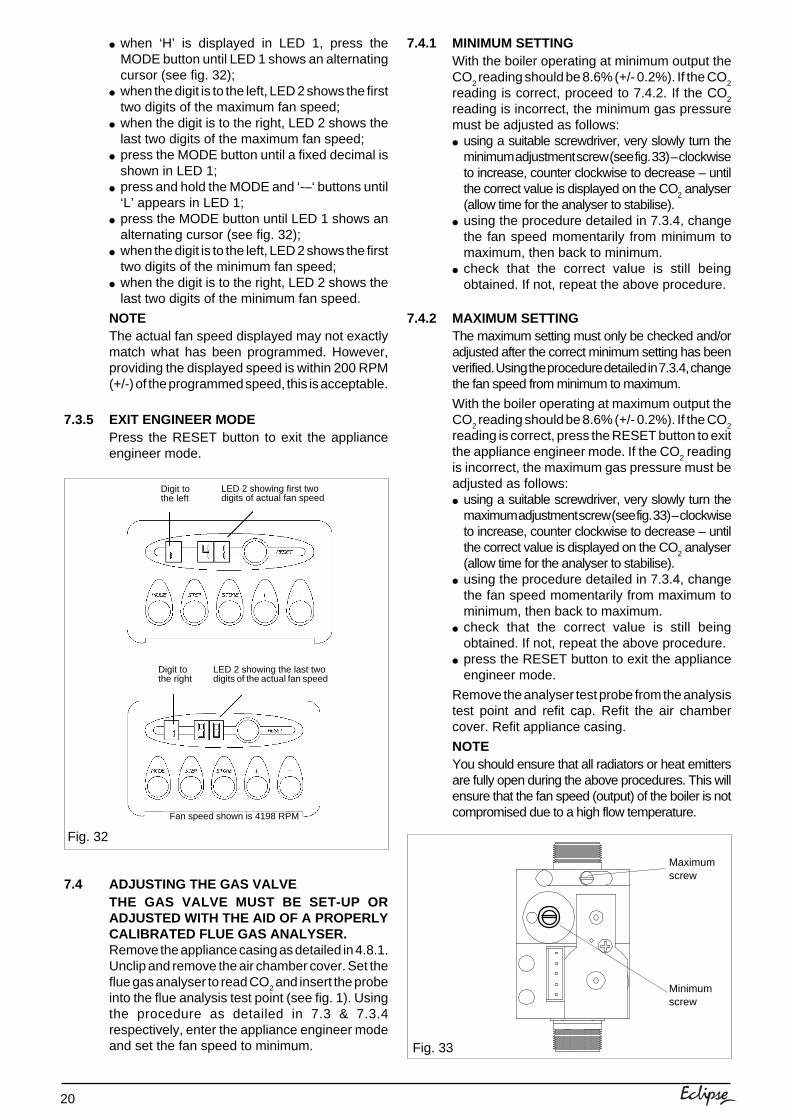
7.4 ADJUSTING THE GAS VALVETHE GAS VALVE MUST BE SET-UP ORADJUSTED WITH THE AID OF A PROPERLYCALIBRATED FLUE GAS ANALYSER.Remove the appliance casing as detailed in 4.8.1.Unclip and remove the air chamber cover. Set theflue gas analyser to read CO
2 and insert the probe
into the flue analysis test point (see fig. 1). Usingthe procedure as detailed in 7.3 & 7.3.4respectively, enter the appliance engineer modeand set the fan speed to minimum.
7.4.1 MINIMUM SETTINGWith the boiler operating at minimum output theCO
2 reading should be 8.6% (+/- 0.2%). If the CO
2
reading is correct, proceed to 7.4.2. If the CO2
reading is incorrect, the minimum gas pressuremust be adjusted as follows:● using a suitable screwdriver, very slowly turn the
minimum adjustment screw (see fig. 33) – clockwiseto increase, counter clockwise to decrease – untilthe correct value is displayed on the CO
2 analyser
(allow time for the analyser to stabilise).● using the procedure detailed in 7.3.4, change
the fan speed momentarily from minimum tomaximum, then back to minimum.
● check that the correct value is still beingobtained. If not, repeat the above procedure.
7.4.2 MAXIMUM SETTINGThe maximum setting must only be checked and/oradjusted after the correct minimum setting has beenverified. Using the procedure detailed in 7.3.4, changethe fan speed from minimum to maximum.
With the boiler operating at maximum output theCO
2 reading should be 8.6% (+/- 0.2%). If the CO
2
reading is correct, press the RESET button to exitthe appliance engineer mode. If the CO
2 reading
is incorrect, the maximum gas pressure must beadjusted as follows:● using a suitable screwdriver, very slowly turn the
maximum adjustment screw (see fig. 33) – clockwiseto increase, counter clockwise to decrease – untilthe correct value is displayed on the CO
2 analyser
(allow time for the analyser to stabilise).● using the procedure detailed in 7.3.4, change
the fan speed momentarily from maximum tominimum, then back to maximum.
● check that the correct value is still beingobtained. If not, repeat the above procedure.
● press the RESET button to exit the applianceengineer mode.
Remove the analyser test probe from the analysistest point and refit cap. Refit the air chambercover. Refit appliance casing.
NOTEYou should ensure that all radiators or heat emittersare fully open during the above procedures. This willensure that the fan speed (output) of the boiler is notcompromised due to a high flow temperature.
Fig. 33
Maximumscrew
Minimumscrew
Fig. 32
Digit tothe left
LED 2 showing first twodigits of actual fan speed
Digit tothe right
LED 2 showing the last twodigits of the actual fan speed
Fan speed shown is 4198 RPM
21
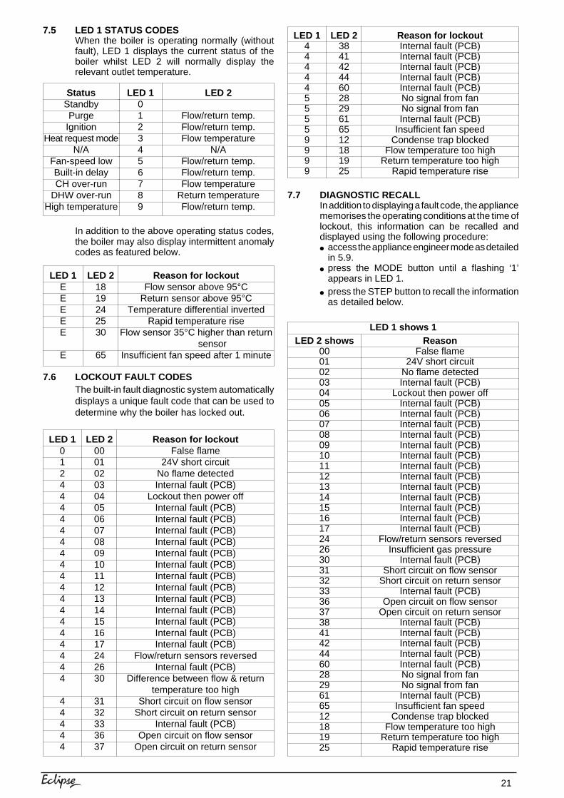
7.5 LED 1 STATUS CODESWhen the boiler is operating normally (withoutfault), LED 1 displays the current status of theboiler whilst LED 2 will normally display therelevant outlet temperature.
In addition to the above operating status codes,the boiler may also display intermittent anomalycodes as featured below.
7.6 LOCKOUT FAULT CODESThe built-in fault diagnostic system automaticallydisplays a unique fault code that can be used todetermine why the boiler has locked out.
7.7 DIAGNOSTIC RECALLIn addition to displaying a fault code, the appliancememorises the operating conditions at the time oflockout, this information can be recalled anddisplayed using the following procedure:● access the appliance engineer mode as detailed
in 5.9.● press the MODE button until a flashing ‘1’
appears in LED 1.● press the STEP button to recall the information
as detailed below.
LED 1EEEEE
E
LED 21819242530
65
Reason for lockoutFlow sensor above 95°C
Return sensor above 95°CTemperature differential inverted
Rapid temperature riseFlow sensor 35°C higher than return
sensorInsufficient fan speed after 1 minute
StatusStandbyPurge
IgnitionHeat request mode
N/AFan-speed lowBuilt-in delayCH over-run
DHW over-runHigh temperature
LED 10123456789
LED 2
Flow/return temp.Flow/return temp.Flow temperature
N/AFlow/return temp.Flow/return temp.Flow temperature
Return temperatureFlow/return temp.
LED 14444455559999
LED 238414244602829616512181925
Reason for lockoutInternal fault (PCB)Internal fault (PCB)Internal fault (PCB)Internal fault (PCB)Internal fault (PCB)No signal from fanNo signal from fanInternal fault (PCB)
Insufficient fan speedCondense trap blocked
Flow temperature too highReturn temperature too high
Rapid temperature rise
LED 1012444444444444444444
44444
LED 2000102030405060708091011121314151617242630
3132333637
Reason for lockoutFalse flame
24V short circuitNo flame detectedInternal fault (PCB)
Lockout then power offInternal fault (PCB)Internal fault (PCB)Internal fault (PCB)Internal fault (PCB)Internal fault (PCB)Internal fault (PCB)Internal fault (PCB)Internal fault (PCB)Internal fault (PCB)Internal fault (PCB)Internal fault (PCB)Internal fault (PCB)Internal fault (PCB)
Flow/return sensors reversedInternal fault (PCB)
Difference between flow & returntemperature too high
Short circuit on flow sensorShort circuit on return sensor
Internal fault (PCB)Open circuit on flow sensor
Open circuit on return sensor
LED 1 shows 1LED 2 shows
000102030405060708091011121314151617242630313233363738414244602829616512181925
ReasonFalse flame
24V short circuitNo flame detectedInternal fault (PCB)
Lockout then power offInternal fault (PCB)Internal fault (PCB)Internal fault (PCB)Internal fault (PCB)Internal fault (PCB)Internal fault (PCB)Internal fault (PCB)Internal fault (PCB)Internal fault (PCB)Internal fault (PCB)Internal fault (PCB)Internal fault (PCB)Internal fault (PCB)
Flow/return sensors reversedInsufficient gas pressure
Internal fault (PCB)Short circuit on flow sensor
Short circuit on return sensorInternal fault (PCB)
Open circuit on flow sensorOpen circuit on return sensor
Internal fault (PCB)Internal fault (PCB)Internal fault (PCB)Internal fault (PCB)Internal fault (PCB)No signal from fanNo signal from fanInternal fault (PCB)
Insufficient fan speedCondense trap blocked
Flow temperature too highReturn temperature too high
Rapid temperature rise
22
LED 1 shows 2
LED 2 shows0123456789
ReasonStandbyPurgeIgnition
Heat requestN/A
Fan-speed lowBuilt-in delay
Pump over-runN/A
High temperature
LED 1 shows 3
LED 2 shows °C Temperature of flow sensor at timeof lockout
LED 1 shows 4LED 2 shows °C Temperature of return sensor at
time of lockout
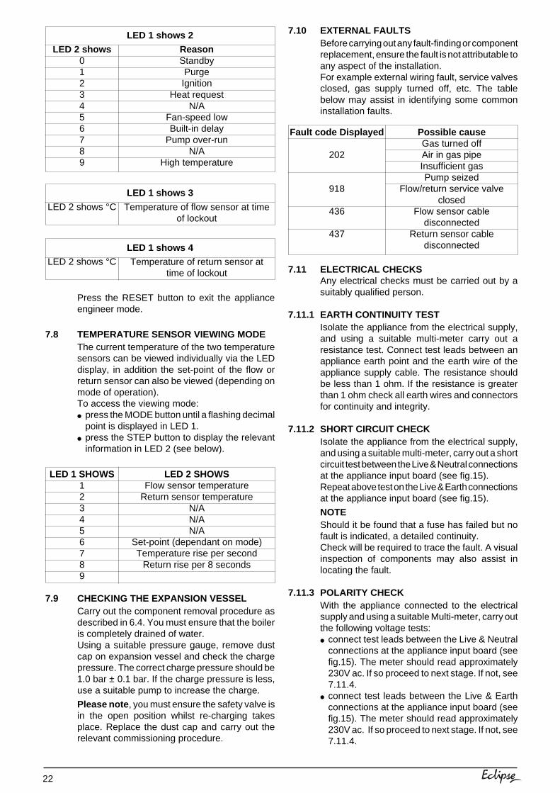
Press the RESET button to exit the applianceengineer mode.
7.8 TEMPERATURE SENSOR VIEWING MODEThe current temperature of the two temperaturesensors can be viewed individually via the LEDdisplay, in addition the set-point of the flow orreturn sensor can also be viewed (depending onmode of operation).To access the viewing mode:● press the MODE button until a flashing decimal
point is displayed in LED 1.● press the STEP button to display the relevant
information in LED 2 (see below).
7.9 CHECKING THE EXPANSION VESSELCarry out the component removal procedure asdescribed in 6.4. You must ensure that the boileris completely drained of water.Using a suitable pressure gauge, remove dustcap on expansion vessel and check the chargepressure. The correct charge pressure should be1.0 bar ± 0.1 bar. If the charge pressure is less,use a suitable pump to increase the charge.
Please note , you must ensure the safety valve isin the open position whilst re-charging takesplace. Replace the dust cap and carry out therelevant commissioning procedure.
LED 1 SHOWS123456789
LED 2 SHOWSFlow sensor temperature
Return sensor temperatureN/AN/AN/A
Set-point (dependant on mode)Temperature rise per second
Return rise per 8 seconds
7.10 EXTERNAL FAULTSBefore carrying out any fault-finding or componentreplacement, ensure the fault is not attributable toany aspect of the installation.For example external wiring fault, service valvesclosed, gas supply turned off, etc. The tablebelow may assist in identifying some commoninstallation faults.
7.11 ELECTRICAL CHECKSAny electrical checks must be carried out by asuitably qualified person.
7.11.1 EARTH CONTINUITY TESTIsolate the appliance from the electrical supply,and using a suitable multi-meter carry out aresistance test. Connect test leads between anappliance earth point and the earth wire of theappliance supply cable. The resistance shouldbe less than 1 ohm. If the resistance is greaterthan 1 ohm check all earth wires and connectorsfor continuity and integrity.
7.11.2 SHORT CIRCUIT CHECKIsolate the appliance from the electrical supply,and using a suitable multi-meter, carry out a shortcircuit test between the Live & Neutral connectionsat the appliance input board (see fig.15).Repeat above test on the Live & Earth connectionsat the appliance input board (see fig.15).
NOTEShould it be found that a fuse has failed but nofault is indicated, a detailed continuity.Check will be required to trace the fault. A visualinspection of components may also assist inlocating the fault.
7.11.3 POLARITY CHECKWith the appliance connected to the electricalsupply and using a suitable Multi-meter, carry outthe following voltage tests:● connect test leads between the Live & Neutral
connections at the appliance input board (seefig.15). The meter should read approximately230V ac. If so proceed to next stage. If not, see7.11.4.
● connect test leads between the Live & Earthconnections at the appliance input board (seefig.15). The meter should read approximately230V ac. If so proceed to next stage. If not, see7.11.4.
Fault code Displayed
202
918
436
437
Possible causeGas turned offAir in gas pipeInsufficient gasPump seized
Flow/return service valveclosed
Flow sensor cabledisconnected
Return sensor cabledisconnected
23
● Connect test leads between the Neutral & Earthconnections at the appliance input board (seefig.15). The meter should read approximately 0– 15Vac. If so polarity is correct. If not, see7.11.4.
7.11.4 REVERSED POLARITY OR SUPPLY FAULTRepeat the above tests at the appliance isolator,if testing reveals correct polarity and/or supply atthe isolator, re-check wiring and connectionsbetween the isolator and the appliance.If tests on the isolator also reveal reversed polarityor a supply fault, consult the local electricitysupplier for advice.
7.11.5 RESISTANCE TO EARTH CHECKIsolate the appliance from the electrical supply,and using a suitable multi-meter carry out aresistance test. Connect test leads between theLive & Earth connections at the appliance inputboard (see fig.15). If the meter reads other thaninfinity there is a fault that must be isolated, carryout a detailed continuity check to identify thelocation of the fault.
IMPORTANTThese series of checks must be carried outbefore attempting any fault-finding procedureson the appliance. On completion of any task thatrequired the disconnection and re-connection ofany electrical wiring or component, these checksmust be repeated.
7.11.6 FUSESThe appliance is equipped with spare fuses.These fuses are located on the covers of theterminal strip and main PCB respectively. If afuse has blown it is usually indicative of anexternal wiring fault or a faulty component suchas the pump, fan, valve actuator, etc. Under nocircumstances should a blown fuse be replacedwith one of a higher rating.
7.12 FAULT FINDINGBEFORE ATTEMPTING ANY FAULTDIAGNOSIS OR REPAIR THE FOLLOWINGPROCEDURE SHOULD BE CARRIED OUT:● carry out the relevant electrical checks as
detailed in 7.11;● disconnect any external wiring from the
appliance terminal strip (terminals 4 & 6) andreplace with a solid link wire;
● ensure the appliance is protected – externally –by a 3 amp fuse.
IMPORTANTThe Eclipse boiler utilises 24V switching. Anyexternal controls that are directly connectedto the boiler must be suitable for 24Vapplications and shall be voltage free. Underno circumstances should a 230V supply beconnected to terminals 4 & 6 of the applianceterminal strip.
FAULT
No display, boilerinactive
No display, pumprunning
No display, pumprunning, fan speed
alternating
No display, boilerworking okay
Pump failure
Fan fault
Ignition fault
GO TO
Test 1Then 1A
Test 1A
Test 1A
Test 1A
Test 2
Test 3
Test 4
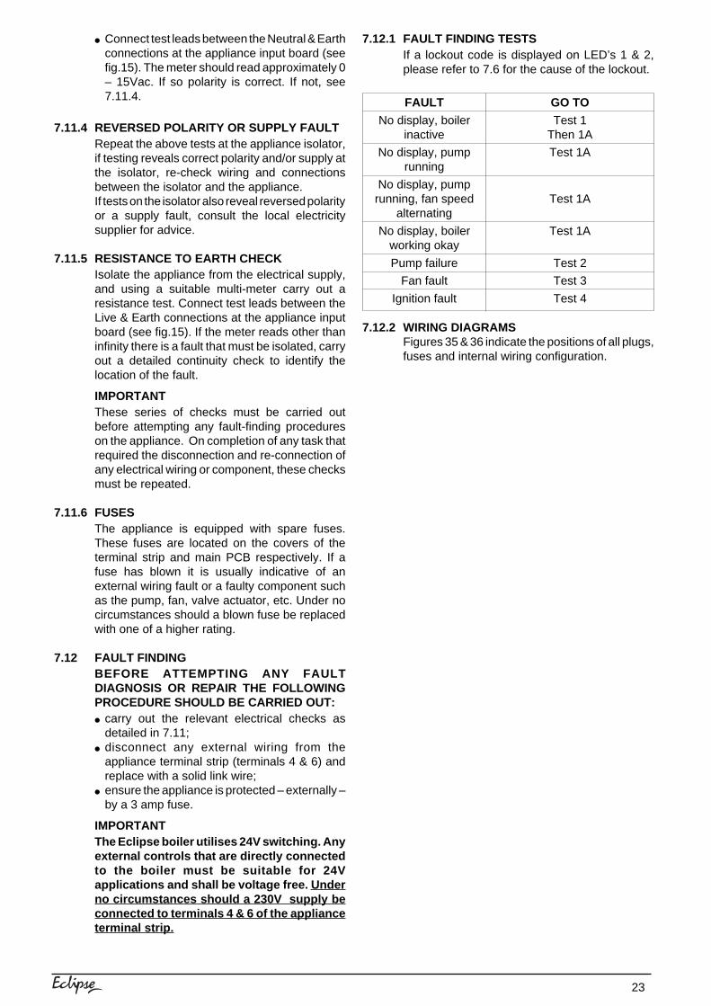
7.12.1 FAULT FINDING TESTSIf a lockout code is displayed on LED’s 1 & 2,please refer to 7.6 for the cause of the lockout.
7.12.2 WIRING DIAGRAMSFigures 35 & 36 indicate the positions of all plugs,fuses and internal wiring configuration.
24
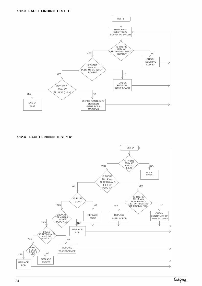
7.12.3 FAULT FINDING TEST ‘1’
TEST1
CHECK
SUPPLYINCOMING
YES NO
NO
CHECKFUSE ON
INPUT BOARDIS THERE
PLUG X1 (L & N)230V AT
YES
YES NO
END OFTEST INPUT PCB &
CHECK CONTINUITYBETWEEN
MAIN PCB
ELECTRICALSUPPLY TO BOILER
SWITCH ON
IS THERE
PLUG M6 ON INPUTBOARD?
230V AT
IS THERE
PLUG M5 ON INPUTBOARD?
230V AT
7.12.4 FAULT FINDING TEST ‘1A’
TEST 1A
IS THERE
AT TERMINALS1 & 7 OF
10-14 Vdc
PLUG X7
GO TOTEST 1
CHECKCONTINUITY OFRIBBON CABLE
REPLACE
DISPLAY PCB
YES NO
YES
TERMINALS230V AT
1 & 3 OFPLUG X10
24Vac
6 & 7 OFPLUG X10 NOYES
YES
IS THERE
PLUG X1230V AT
(L & N)YES NO
YES
1 & 7 OF PLUG X7a
IS THERE
AT TERMINALS10-14 Vdc
OF DISPLAY PCB NOYES
NO
IS FUSE
F1 OK?
NO
AT TERMINALS
REPLACE
TRANSFORMER
ARE
F2 & F3FUSES
OK? NO
REPLACEFUSE
REPLACEPCB
REPLACEPCB
REPLACEFUSE/S
25
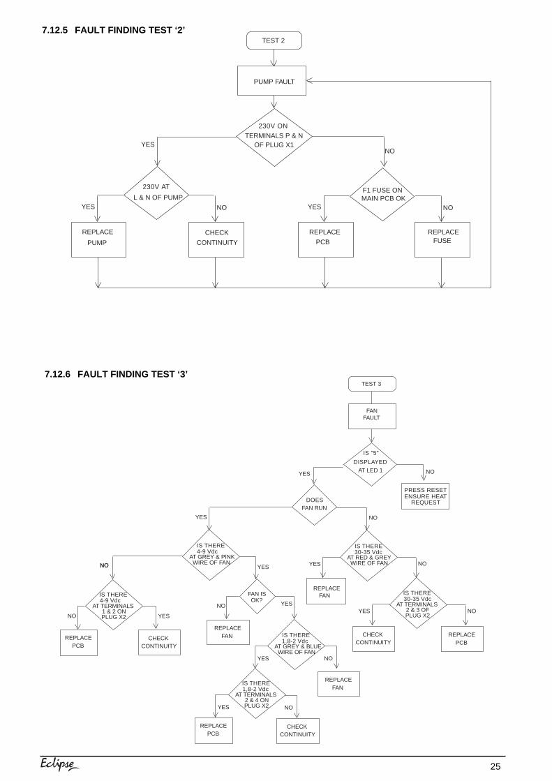
7.12.5 FAULT FINDING TEST ‘2’TEST 2
TERMINALS P & N
PUMP FAULT
230V ON
OF PLUG X1
MAIN PCB OK
NOYES
L & N OF PUMP
230V AT
NO
CHECK
CONTINUITY
YES
PUMP
REPLACE
NO
FUSE
YES
PCB
REPLACE
F1 FUSE ON
REPLACE
7.12.6 FAULT FINDING TEST ‘3’TEST 3
REPLACEFAN
IS "5"
AT LED 1YES NO
NO
NO
FANFAULT
DISPLAYED
PRESS RESETENSURE HEAT
REQUESTDOESFAN RUN
YES NO
IS THERE
AT RED & GREY30-35 Vdc
WIRE OF FAN
YES NO
REPLACEFAN REPLACE
PCB
IS THERE
AT GREY & PINK4-9 Vdc
WIRE OF FANYES
FAN ISOK?
YES
NO
IS THERE
AT TERMINALS30-35 Vdc
2 & 3 OFPLUG X2
NO
REPLACEPCB
REPLACEPCB
NO YES
CONTINUITYCHECK
CONTINUITYCHECK IS THERE
AT GREY & BLUE1,8-2 Vdc
WIRE OF FAN
YES
REPLACEFAN
IS THERE
AT TERMINALS4-9 Vdc
1 & 2 ONPLUG X2
IS THERE
AT TERMINALS1,8-2 Vdc
2 & 4 ONPLUG X2
NO
NO
YES
YES
CONTINUITYCHECK
26
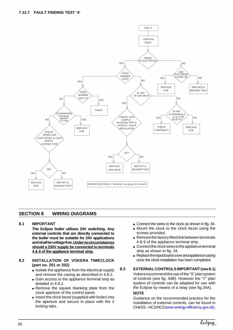
8.1 IMPORTANTThe Eclipse boiler utilises 24V switching. Anyexternal controls that are directly connected tothe boiler must be suitable for 24V applicationsand shall be voltage free. Under no circumstancesshould a 230V supply be connected to terminals4 & 6 of the appliance terminal strip.
8.2 INSTALLATION OF VOKERA TIMECLOCK(part no. 201 or 202)● Isolate the appliance from the electrical supply
and remove the casing as described in 4.8.1.● Gain access to the appliance terminal strip as
detailed in 4.8.2.● Remove the square blanking plate from the
clock aperture of the control panel.● Insert the clock bezel (supplied with boiler) into
the aperture and secure in place with the 2locking tabs.
7.12.7 FAULT FINDING TEST ‘4’
TEST 4
SPARK
YES
IGNITIONFAULT
AT ELECTRODE
FINISH
REPLACEPCB
YES
NO
ARE
YES NO
ELECTRODE& LEAD OK
NO
AT GAS VALVE24 VAC
YES
AT TERMINALS24 VAC
11 & 12 OFPLUG X2
CONTINUITYCHECK
NO
REPLACEPCB
DOESBURNERLIGHT
YES NO
REPLACE &RESTART TEST
DOESBURNERSTAY LIT
YESNO
NO YES
IS IONISATIONVOLTAGE
ABOVE2,0 Vdc
REPLACEPCB
SILICONE PIPE &NOZZLE, VALVE
CHECK: GAS
REGULATOR
SUPPLY,
OK?
REPLACE
YES NO
GAS VALVE
RECTIFY &RESTART TEST
IONISATION CHECK: Terminal 5 on plug X2 to Earth
ELECTRODE & LEAD,
CHECK:SPARK GAP,
EARTHCONNECTION
OK?
YES NO
RECTIFY &RESTART TEST
REPLACEPCB
SECTION 8 WIRING DIAGRAMS
● Connect the wires to the clock as shown in fig. 34.● Mount the clock to the clock bezel using the
screws provided.● Remove the factory fitted link between terminals
4 & 6 of the appliance terminal strip.● Connect the clock wires to the appliance terminal
strip as shown in fig. 34.● Replace the input board cover and appliance casing
once the clock installation has been completed.
8.3 EXTERNAL CONTROLS IMPORTANT (see 8.1)Vokera recommend the use of the “S” plan systemof controls (see fig. 34B). However the “Y” plansystem of controls can be adapted for use withthe Eclipse by means of a relay (see fig.34A).NOTEGuidance on the recommended practice for theinstallation of external controls, can be found inCHeSS – HC1/HC2 (www.energy-efficiency.gov.uk).
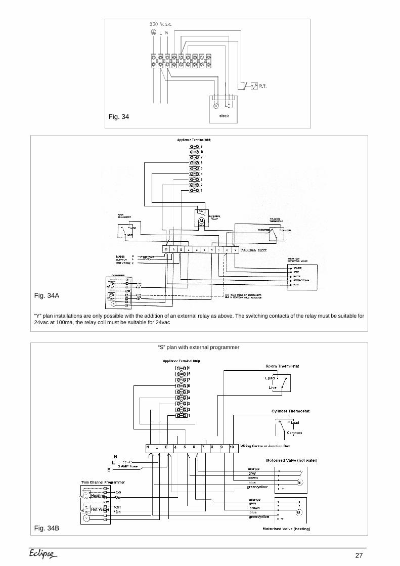
27
Fig. 34
Fig. 34B
“Y” plan installations are only possible with the addition of an external relay as above. The switching contacts of the relay must be suitable for24vac at 100ma, the relay coll must be suitable for 24vac
Fig. 34A
“S” plan with external programmer
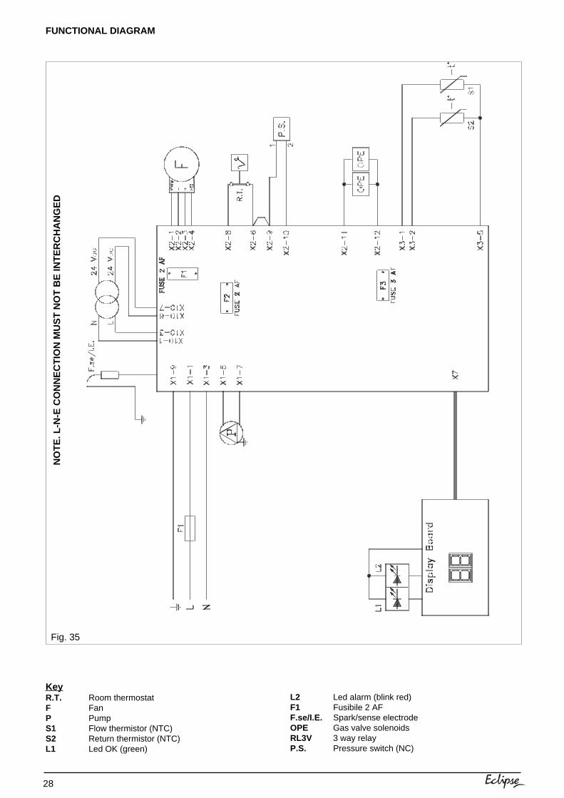
28
FUNCTIONAL DIAGRAM
NO
TE
. L-N
-E C
ON
NE
CT
ION
MU
ST
NO
T B
E IN
TE
RC
HA
NG
ED
KeyR.T. Room thermostatF FanP PumpS1 Flow thermistor (NTC)S2 Return thermistor (NTC)L1 Led OK (green)
Fig. 35
L2 Led alarm (blink red)F1 Fusibile 2 AFF.se/I.E. Spark/sense electrodeOPE Gas valve solenoidsRL3V 3 way relayP.S. Pressure switch (NC)
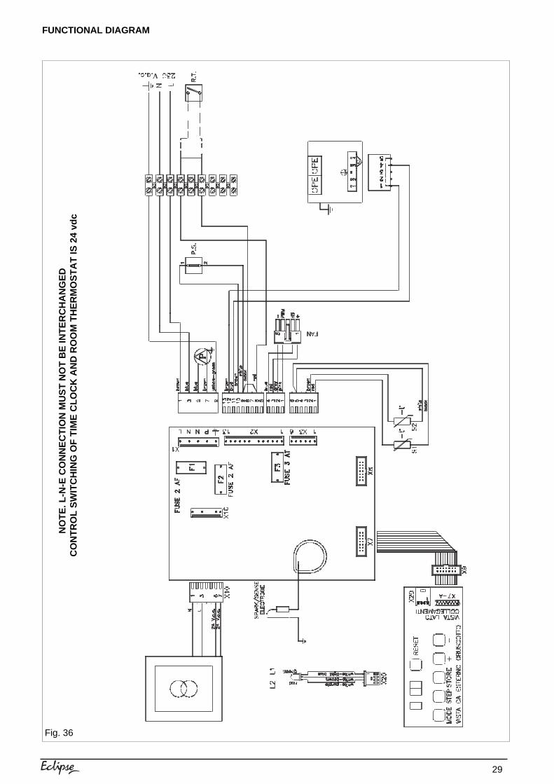
29
NO
TE
. L-N
-E C
ON
NE
CT
ION
MU
ST
NO
T B
E IN
TE
RC
HA
NG
ED
CO
NT
RO
L S
WIT
CH
ING
OF
TIM
E C
LOC
K A
ND
RO
OM
TH
ER
MO
ST
AT
IS 2
4 vd
c
FUNCTIONAL DIAGRAM
Fig. 36
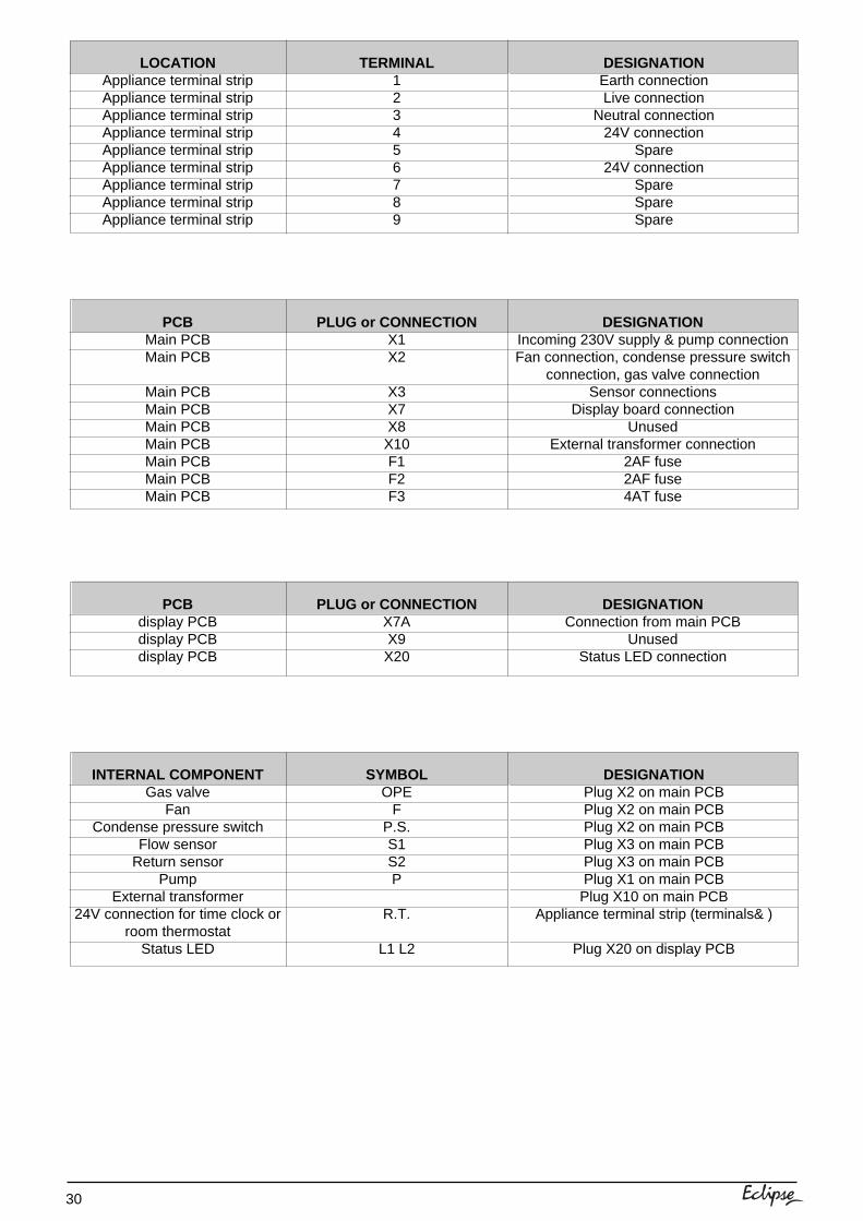
30
PCBdisplay PCBdisplay PCBdisplay PCB
INTERNAL COMPONENTGas valve
FanCondense pressure switch
Flow sensorReturn sensor
PumpExternal transformer
24V connection for time clock orroom thermostat
Status LED
SYMBOLOPE
FP.S.S1S2P
R.T.
L1 L2
DESIGNATIONPlug X2 on main PCBPlug X2 on main PCBPlug X2 on main PCBPlug X3 on main PCBPlug X3 on main PCBPlug X1 on main PCBPlug X10 on main PCB
Appliance terminal strip (terminals& )
Plug X20 on display PCB
PLUG or CONNECTIONX7AX9X20
DESIGNATIONConnection from main PCB
UnusedStatus LED connection
LOCATIONAppliance terminal stripAppliance terminal stripAppliance terminal stripAppliance terminal stripAppliance terminal stripAppliance terminal stripAppliance terminal stripAppliance terminal stripAppliance terminal strip
TERMINAL123456789
DESIGNATIONEarth connectionLive connection
Neutral connection24V connection
Spare24V connection
SpareSpareSpare
PCBMain PCBMain PCB
Main PCBMain PCBMain PCBMain PCBMain PCBMain PCBMain PCB
PLUG or CONNECTIONX1X2
X3X7X8X10F1F2F3
DESIGNATIONIncoming 230V supply & pump connectionFan connection, condense pressure switch
connection, gas valve connectionSensor connections
Display board connectionUnused
External transformer connection2AF fuse2AF fuse4AT fuse
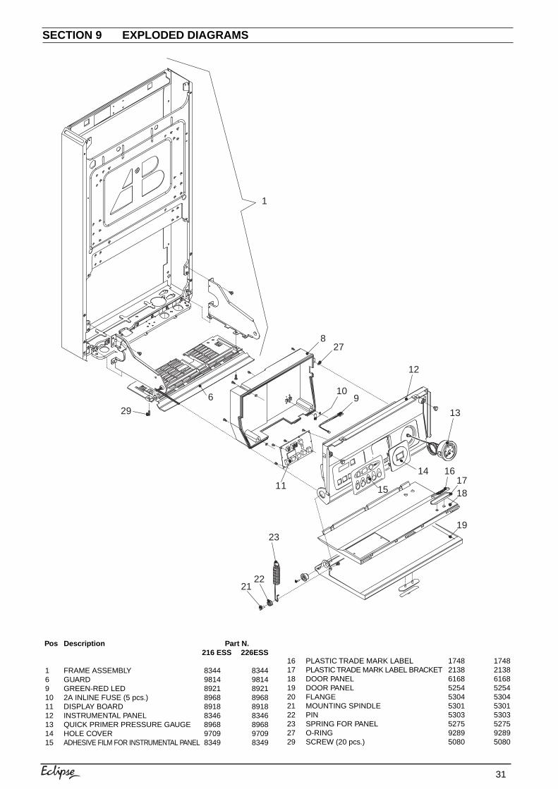
31
SECTION 9 EXPLODED DIAGRAMS
Pos Description Part N.216 ESS 226ESS
1 FRAME ASSEMBLY 8344 83446 GUARD 9814 98149 GREEN-RED LED 8921 892110 2A INLINE FUSE (5 pcs.) 8968 896811 DISPLAY BOARD 8918 891812 INSTRUMENTAL PANEL 8346 834613 QUICK PRIMER PRESSURE GAUGE 8968 896814 HOLE COVER 9709 970915 ADHESIVE FILM FOR INSTRUMENTAL PANEL 8349 8349
16 PLASTIC TRADE MARK LABEL 1748 174817 PLASTIC TRADE MARK LABEL BRACKET 2138 213818 DOOR PANEL 6168 616819 DOOR PANEL 5254 525420 FLANGE 5304 530421 MOUNTING SPINDLE 5301 530122 PIN 5303 530323 SPRING FOR PANEL 5275 527527 O-RING 9289 928929 SCREW (20 pcs.) 5080 5080
1
296
827
910
11
12
13
14
15
161718
1923
2221
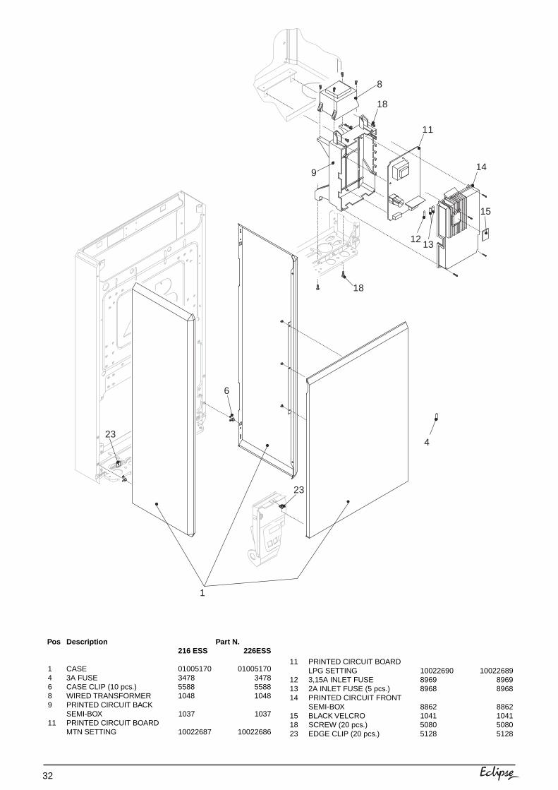
32
Pos Description Part N.216 ESS 226ESS
1 CASE 01005170 010051704 3A FUSE 3478 34786 CASE CLIP (10 pcs.) 5588 55888 WIRED TRANSFORMER 1048 10489 PRINTED CIRCUIT BACK
SEMI-BOX 1037 103711 PRINTED CIRCUIT BOARD
MTN SETTING 10022687 10022686
8
18
11
14
15
1312
18
9
6
23
234
1
11 PRINTED CIRCUIT BOARDLPG SETTING 10022690 10022689
12 3,15A INLET FUSE 8969 896913 2A INLET FUSE (5 pcs.) 8968 896814 PRINTED CIRCUIT FRONT
SEMI-BOX 8862 886215 BLACK VELCRO 1041 104118 SCREW (20 pcs.) 5080 508023 EDGE CLIP (20 pcs.) 5128 5128
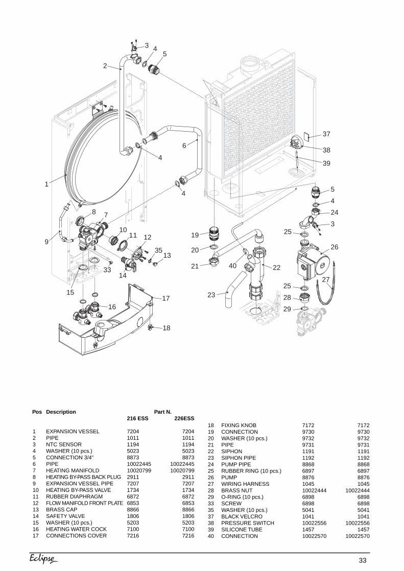
33
Pos Description Part N.216 ESS 226ESS
1 EXPANSION VESSEL 7204 72042 PIPE 1011 10113 NTC SENSOR 1194 11944 WASHER (10 pcs.) 5023 50235 CONNECTION 3/4” 8873 88736 PIPE 10022445 100224457 HEATING MANIFOLD 10020799 100207998 HEATING BY-PASS BACK PLUG 2911 29119 EXPANSION VESSEL PIPE 7207 720710 HEATING BY-PASS VALVE 1734 173411 RUBBER DIAPHRAGM 6872 687212 FLOW MANIFOLD FRONT PLATE 6853 685313 BRASS CAP 8866 886614 SAFETY VALVE 1806 180615 WASHER (10 pcs.) 5203 520316 HEATING WATER COCK 7100 710017 CONNECTIONS COVER 7216 7216
18 FIXING KNOB 7172 717219 CONNECTION 9730 973020 WASHER (10 pcs.) 9732 973221 PIPE 9731 973122 SIPHON 1191 119123 SIPHON PIPE 1192 119224 PUMP PIPE 8868 886825 RUBBER RING (10 pcs.) 6897 689726 PUMP 8876 887627 WIRING HARNESS 1045 104528 BRASS NUT 10022444 1002244429 O-RING (10 pcs.) 6898 689833 SCREW 6898 689835 WASHER (10 pcs.) 5041 504137 BLACK VELCRO 1041 104138 PRESSURE SWITCH 10022556 1002255639 SILICONE TUBE 1457 145740 CONNECTION 10022570 10022570
3314
8
1011 12
35
15
4
18
1716
7
13
9
1
2
3 45
4
6
19
20
21
23
22
5
4
24
3
26
25
25
28
29
27
40
37
38
39
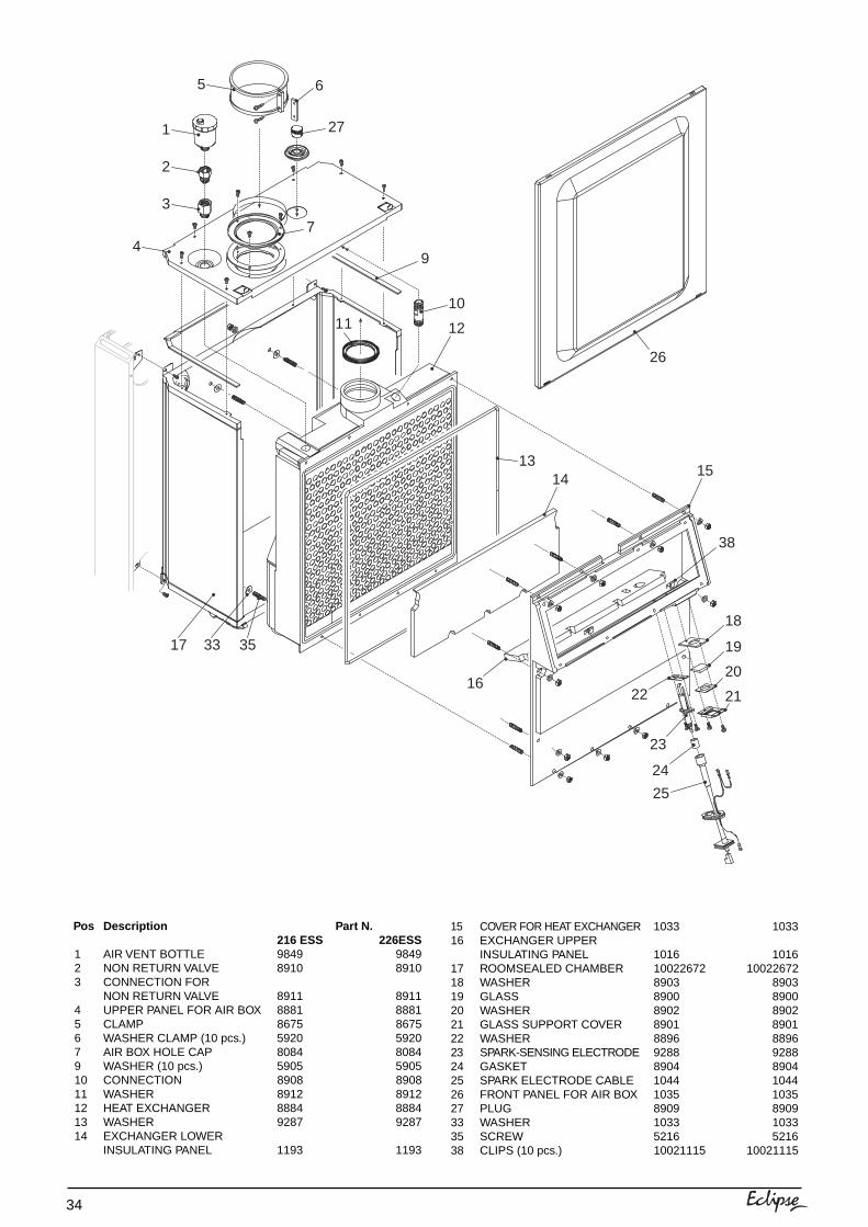
34
Pos Description Part N.216 ESS 226ESS
1 AIR VENT BOTTLE 9849 98492 NON RETURN VALVE 8910 89103 CONNECTION FOR
NON RETURN VALVE 8911 89114 UPPER PANEL FOR AIR BOX 8881 88815 CLAMP 8675 86756 WASHER CLAMP (10 pcs.) 5920 59207 AIR BOX HOLE CAP 8084 80849 WASHER (10 pcs.) 5905 590510 CONNECTION 8908 890811 WASHER 8912 891212 HEAT EXCHANGER 8884 888413 WASHER 9287 928714 EXCHANGER LOWER
INSULATING PANEL 1193 1193
15 COVER FOR HEAT EXCHANGER 1033 103316 EXCHANGER UPPER
INSULATING PANEL 1016 101617 ROOMSEALED CHAMBER 10022672 1002267218 WASHER 8903 890319 GLASS 8900 890020 WASHER 8902 890221 GLASS SUPPORT COVER 8901 890122 WASHER 8896 889623 SPARK-SENSING ELECTRODE 9288 928824 GASKET 8904 890425 SPARK ELECTRODE CABLE 1044 104426 FRONT PANEL FOR AIR BOX 1035 103527 PLUG 8909 890933 WASHER 1033 103335 SCREW 5216 521638 CLIPS (10 pcs.) 10021115 10021115
1
2
3
4
5
7
27
6
33 3517
9
10
1211
1314
26
16
15
18
19
20
21
25
24
23
22
38
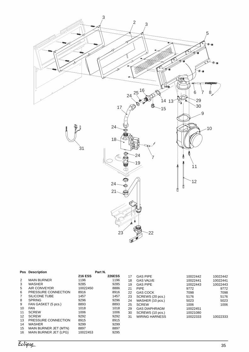
35
Pos Description Part N.216 ESS 226ESS
2 MAIN BURNER 1196 11963 WASHER 9285 92855 AIR CONVEYOR 10022450 88866 PRESSURE CONNECTION 8916 89167 SILICONE TUBE 1457 14578 SPRING 9296 92969 FAN GASKET (5 pcs.) 8893 889310 FAN 1018 101811 SCREW 1006 100612 SCREW 9292 929213 PRESSURE CONNECTION 8915 891514 WASHER 9299 929915 MAIN BURNER JET (MTN) 8897 889716 MAIN BURNER JET (LPG) 10022453 9295
17 GAS PIPE 10022442 1002244218 GAS VALVE 10022441 1002244119 GAS PIPE 10022443 1002244321 PIPE 9772 977222 GAS COCK 7098 709823 SCREWS (20 pcs.) 5176 517624 WASHER (10 pcs.) 5023 502325 SCREW 1006 100629 GAS DIAPHRAGM 1002245130 SCREWS (10 pcs.) 1002108031 WIRING HARNESS 10022333 10022333
32 3
5
6 7 8
9
10
11
12
13
15
14
162524
17
24
18
24
19
24
21
23 22
7
3029
31
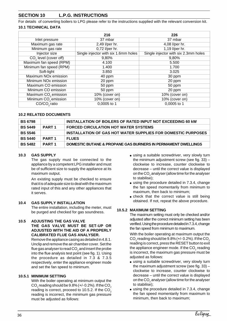
36
SECTION 10 L.P.G. INSTRUCTIONS
10.3 GAS SUPPLYThe gas supply must be connected to theappliance by a competent LPG installer and mustbe of sufficient size to supply the appliance at itsmaximum output.
An existing supply must be checked to ensurethat it is of adequate size to deal with the maximumrated input of this and any other appliances thatit serves.
10.4 GAS SUPPLY INSTALLATIONThe entire installation, including the meter, mustbe purged and checked for gas soundness.
10.5 ADJUSTING THE GAS VALVETHE GAS VALVE MUST BE SET-UP ORADJUSTED WITH THE AID OF A PROPERLYCALIBRATED FLUE GAS ANALYSER.Remove the appliance casing as detailed in 4.8.1.Unclip and remove the air chamber cover. Set theflue gas analyser to read CO
2 and insert the probe
into the flue analysis test point (see fig. 1). Usingthe procedure as detailed in 7.3 & 7.3.5respectively, enter the appliance engineer modeand set the fan speed to minimum.
10.5.1 MINIMUM SETTINGWith the boiler operating at minimum output theCO
2 reading should be 9.8% (+/- 0.2%). If the CO
2
reading is correct, proceed to 10.5.2. If the CO2
reading is incorrect, the minimum gas pressuremust be adjusted as follows:
For details of converting boilers to LPG please refer to the instructions supplied with the relevant conversion kit.
● using a suitable screwdriver, very slowly turnthe minimum adjustment screw (see fig. 33) –clockwise to increase, counter clockwise todecrease – until the correct value is displayedon the CO
2 analyser (allow time for the analyser
to stabilise);● using the procedure detailed in 7.3.4, change
the fan speed momentarily from minimum tomaximum, then back to minimum;
● check that the correct value is still beingobtained. If not, repeat the above procedure.
10.5.2 MAXIMUM SETTINGThe maximum setting must only be checked and/oradjusted after the correct minimum setting has beenverified. Using the procedure detailed in 7.3.4, changethe fan speed from minimum to maximum.
With the boiler operating at maximum output theCO
2 reading should be 9.8% (+/- 0.2%). If the CO
2
reading is correct, press the RESET button to exitthe appliance engineer mode. If the CO
2 reading
is incorrect, the maximum gas pressure must beadjusted as follows:● using a suitable screwdriver, very slowly turn
the maximum adjustment screw (see fig. 33) –clockwise to increase, counter clockwise todecrease – until the correct value is displayedon the CO
2 analyser (allow time for the analyser
to stabilise);● using the procedure detailed in 7.3.4, change
the fan speed momentarily from maximum tominimum, then back to maximum;
10.1 TECHNICAL DATA
10.2 RELATED DOCUMENTS
BS 6798
BS 5449
BS 5546BS 5440
BS 5482
PART 1
PART 1
PART 1
INSTALLATION OF BOILERS OF RATED INPUT NOT EXCEEDING 60 kW
FORCED CIRCULATION HOT WATER SYSTEMS
INSTALLATION OF GAS HOT WATER SUPPLIES FOR DOMESTIC PURPOSESFLUES
DOMESTIC BUTANE & PROPANE GAS BURNERS IN PERMAMENT DWELLINGS
Inlet pressureMaximum gas rateMinimum gas rate
Injector sizeCO
2 level (cover off)
Maximum fan speed (RPM)Minimum fan speed (RPM)
Soft-lightMaximum NOx emissionMinimum NOx emissionMaximum CO emissionMinimum CO emissionMaximum CO
2 emission
Minimum CO2 emission
CO/CO2 ratio
21637 mbar
2,49 l/per hr.0,72 l/per hr.
Single injector with six 1.6mm holes9,80%4.1001.4003.850
40 ppm20 ppm50 ppm50 ppm
10% (cover on)10% (cover on)
0,0005 to 1
22637 mbar
4,08 l/per hr.1,19 l/per hr.
Single injector with six 2.3mm holes9,80%5.5001.7003.025
30 ppm20 ppm50 ppm20 ppm
10% (cover on)10% (cover on)
0,0005 to 1
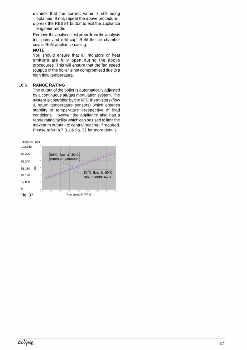
37
Fig. 37 Fan speed in RPM
kW
Output BTU/H
102,360
68,240
17,060
0
51,180
34,120
85,300
● check that the correct value is still beingobtained. If not, repeat the above procedure;
● press the RESET button to exit the applianceengineer mode.
Remove the analyser test probe from the analysistest point and refit cap. Refit the air chambercover. Refit appliance casing.NOTEYou should ensure that all radiators or heatemitters are fully open during the aboveprocedures. This will ensure that the fan speed(output) of the boiler is not compromised due to ahigh flow temperature.
10.6 RANGE RATINGThe output of the boiler is automatically adjustedby a continuous air/gas modulation system. Thesystem is controlled by the NTC thermistors (flow& return temperature sensors) which ensuresstability of temperature irrespective of loadconditions. However the appliance also has arange rating facility which can be used to limit themaximum output - to central heating- if required.Please refer to 7.3.1 & fig. 37 for more details.
0
5
10
15
20
25
30
1500 2000 2500 3000 3500 4000 4500 5000 5500
50°C flow & 30°Creturn temperature
80°C flow & 60°Creturn temperature

Cod
. 100
2244
7 -
Ed.
2 -
16/
02
Vokèra Ltd.4th Floor, Catherine House, Boundary Way, Hemel Hempstead, Herts, HP2 7RP
Email: [email protected] Web: www.vokera.co.ukGeneral Enquiries - Tel: 01442 281400 Fax: 01442 281460
Technical Advice - Tel: 0141 945 6810Spare Parts - Tel: 0141 945 6820
After Sales Service - Tel: 0870 333 0220
Vokèra IrelandWest Court, Callan, Co Kilkenny
Tel: 056 55057 Fax: 056 55060
Vokèra Ltd. reserve the right to change the specifications without prior notice. Consumers’ statutory rights are not affected.
A Riello Group Company
energizing home heating
“Vokèra”supports Benchmark
COLLECTIVE MARK