Embed Size (px)
Citation preview
05/29/2018 1/2E
If light doesn’t turn on, check the battery to ensure that it is making secure contact with the terminals. If this doesn’t work, replace with a new battery.
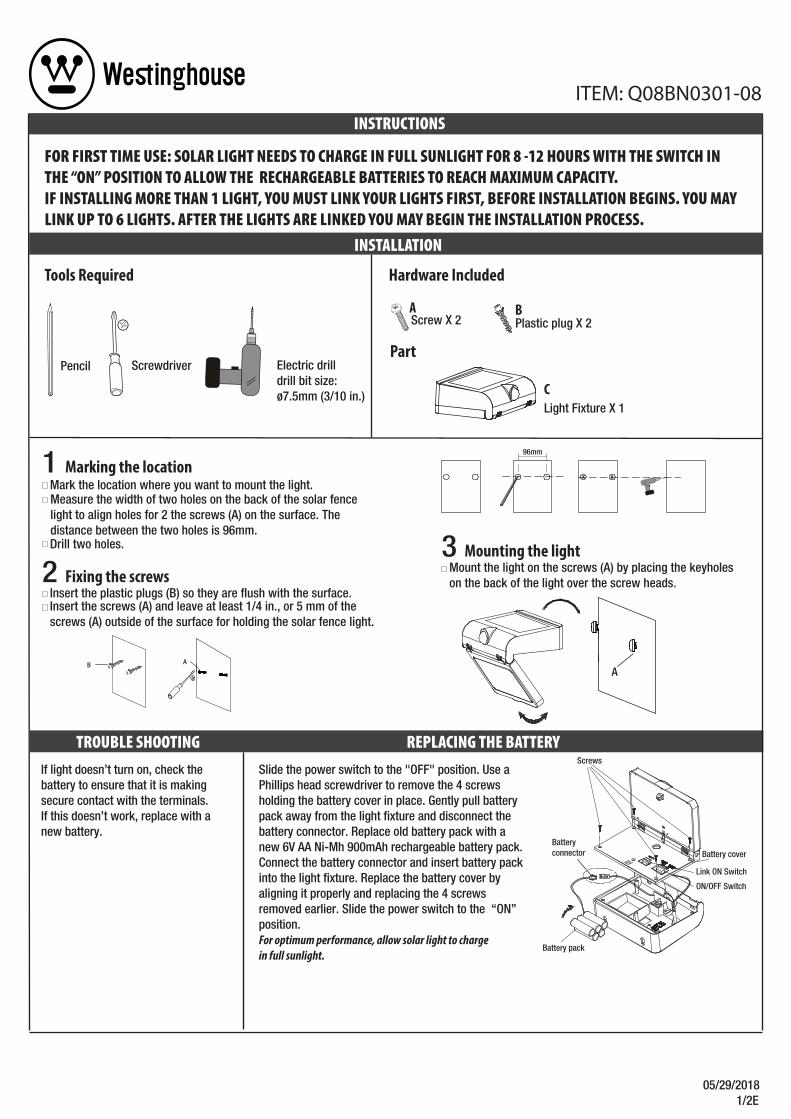
Tools Required
ScrewdriverPencil Electric drill drill bit size: ø7.5mm (3/10 in.)
Mark the location where you want to mount the light.
Drill two holes.
1 Marking the location
Measure the width of two holes on the back of the solar fence light to align holes for 2 the screws (A) on the surface. The distance between the two holes is 96mm.
2 Fixing the screws
Insert the screws (A) and leave at least 1/4 in., or 5 mm of the screws (A) outside of the surface for holding the solar fence light.
Insert the plastic plugs (B) so they are flush with the surface.
REPLACING THE BATTERYTROUBLE SHOOTING
FOR FIRST TIME USE: SOLAR LIGHT NEEDS TO CHARGE IN FULL SUNLIGHT FOR 8 -12 HOURS WITH THE SWITCH IN THE “ON” POSITION TO ALLOW THE RECHARGEABLE BATTERIES TO REACH MAXIMUM CAPACITY. IF INSTALLING MORE THAN 1 LIGHT, YOU MUST LINK YOUR LIGHTS FIRST, BEFORE INSTALLATION BEGINS. YOU MAY LINK UP TO 6 LIGHTS. AFTER THE LIGHTS ARE LINKED YOU MAY BEGIN THE INSTALLATION PROCESS.
INSTALLATION
INSTRUCTIONS
Hardware Included
Plastic plug X 2 Screw X 2
Part
Light Fixture X 1
A B
C
ITEM: Q08BN0301-08
3 Mounting the lightMount the light on the screws (A) by placing the keyholes on the back of the light over the screw heads.
x x
96mm
B A
Slide the power switch to the "OFF" position. Use a Phillips head screwdriver to remove the 4 screws holding the battery cover in place. Gently pull battery pack away from the light fixture and disconnect the battery connector. Replace old battery pack with a new 6V AA Ni-Mh 900mAh rechargeable battery pack. Connect the battery connector and insert battery pack into the light fixture. Replace the battery cover by aligning it properly and replacing the 4 screws removed earlier. Slide the power switch to the “ON” position. For optimum performance, allow solar light to charge in full sunlight.
A
Screws
Battery cover
Battery pack
Battery connector
ON/OFF Switch
Link ON Switch
05/29/2018 1/2S
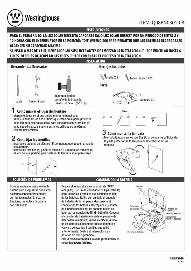
Si no se enciende la luz, revise la batería para asegurarse que estén haciendo contacto firmemente con las terminales. Si esto no funciona, reemplace la batería con una nueva.
Herramientas Necesarias
Lápiz
PARA EL PRIMER USO: LA LUZ SOLAR NECESITA CARGARSE BAJO LUZ SOLAR DIRECTA POR UN PERIODO DE ENTRE 8 Y 12 HORAS CON EL INTERRUPTOR EN LA POSICIÓN "ON" (PRENDIDO) PARA PERMITIR QUE LAS BATERÍAS RECARGABLES ALCANCEN SU CAPACIDAD MÁXIMA. SI INSTALA MÁS DE 1 LUZ, DEBE ACOPLAR SUS LUCES ANTES DE EMPEZAR LA INSTALACIÓN. PUEDE VINCULAR HASTA 6 LUCES. DESPUÉS DE ACOPLAR LAS LUCES, PUEDE COMENZAR EL PROCESO DE INSTALACIÓN.
INSTALACIÓN
INSTRUCCIONES
Destornillador
Taladro eléctricotamaño de la broca detaladro: ø7.5 mm (3/10 plg)
SOLUCIÓN DE PROBLEMAS CAMBIANDO LA BATERÍA
Herrajes Incluidos
Tápon plástico X 2 Tornillo X 2
Parte
A B
ITEM: Q08BN0301-08
Lámpara X 1C
Marque el lugar en el que quiere montar el panel solar.
Taladre dos orificios.
1 Cómo marcar el lugar de montaje
Mide el ancho de los dos orificios que están en la parte posteriorde la lámpara solar para cerca para alinearlos con 2 tornillos (A) en la superficie. La distancia entre los orificios es de 96mm.
3 Cómo montar la lámparaMonta la lámpara en los tornillos (A) al colocarlos orificios de la parte posterior de la lámpara en las cabezas de los tornillos.
x x
96mm
2 Cómo �jar los tornillos
Inserta los tornillos (A) y deja al menos 5 o 6 mmde los tornillos (A) afuera de la superficie para sostener la lámpara solar para cerca.
Inserta los tapones de plástico (B) de manera que queden al ras de la superficie.
B A
Deslice el interruptor a su posición de "OFF" (apagado). Use un destornillador Phillips (estrella) para retirar los 4 tornillos que sostienen la tapa de las baterías. Retire con cuidado el paquete de baterías de la lámpara y desconecte el conector de las baterías. Reemplace el paquete de baterías usadas por un paquete nuevo de baterías recargables 6V Ni-Mh 900mAh. Conecte el conector de baterías e inserte el paquete de bateríasen la lámpara. Vuelva a colocar la tapa de las baterías alineándola adecuadamente y vuelva a colocar los 4 tornillos que retiró anteriormente. Deslice el interruptor a su posición de "ON" (prendido). Para un rendimiento óptimo, permita que la luz solar se cargue bajo directa luz de sol.
A
Tornillos
Tapa de las baterías
Paquete de baterías
Conector de las baterías
Interruptor de Encendido/Apagado
Interruptor de enlace
05/29/2018 2/2E
WARNING: Do not dispose of Ni-Mh batteries in municipal waste stream or by fire as batteries may explode. Do not open, short circuit, or mutilate batteries. Dispose of batteries in accordance with Local, State, and Federal regulations. Do not mix old and new batteries. Do not mix alkaline, standard (Carbon-Zinc), or rechargeable (Nickel Cadmium or Nickel Metal Hydride) batteries .
LINKABLE SET-UP INSTRUCTIONS
ITEM: Q08BN0301-08
For additional help and information regarding installation, contact customer service at 1-844-551-0680, 8am-5pm, CST Monday – [email protected]
, WESTINGHOUSE, are trademarks of Westinghouse Electric Corporation. Used under license by Sky Rich Star Limited. All Rights Reserved.
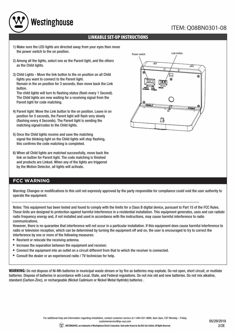
1) Make sure the LED lights are directed away from your eyes then move the power switch to the on position.
2) Among all the lights, select one as the Parent light, and the others as the Child lights. 3) Child Lights - Move the link button to the on position on all Child lights you want to connect to the Parent light. Remain in the on position for 3 seconds, then move back the Link button. The child lights will turn to flashing status (flash every 1 Second). The Child lights are now waiting for a receiving signal from the Parent light for code matching.
4) Parent light: Move the Link button to the on position. Leave in on position for 5 seconds, the Parent light will flash very slowly (flashing every 4 Seconds). The Parent light is sending the matching signal/codes to the Child lights. 5) Once the Child lights receive and save the matching signal the blinking light on the Child lights will stop flashing, this confirms the code matching is completed.
6) When all Child lights are matched successfully, move back the link on button for Parent light. The code matching is finished and products are Linked. When any of the lights are triggered by the Motion Detector, all lights will activate.
Link buttonPower switch
FCC WARNING
Warning: Changes or modifications to this unit not expressly approved by the party responsible for compliance could void the user authority to operate the equipment.
Notes: This equipment has been tested and found to comply with the limits for a Class B digital device, pursuant to Part 15 of the FCC Rules. These linits are designed to protection against harmful interference in a residential installation. This equipment generates, uses and can radiate radio frequency enerqy and, if not installed and used in accordance with the instructions, may cause harmful interference to radio communications. However, there is no quarantee that interference will not occur in a particular installation. If this equipment does cause harmful interference to radio or television reception, which can be determined by turning the equipment off and on, the user is encouraged to try to correct the interference by one or more of the following measures:
Reorient or relocate the receiving antenna.Increase the separation between the equipment and receiver.Connect the equipment into an outlet on a circuit different from that to which the receiver is connected.Consult the dealer or an experienced radio / TV technician for help.
CUIDADO: No deseche las baterías de Ni-Mh en la corriente de desechos municipales o por el fuego, ya que las baterías pueden explotar. No abra, provoque cortocircuitos ni mutile las baterías. Deseche las baterías de acuerdo con los reglamentos locales, estatales y federales. No mezcle las baterías viejas con las nuevas. No mezcle las baterías alcalinas, estándar (carbono-zinc) ni recargables (níquel-cadmio o níquel e hidruro metálico).
ITEM: Q08BN0301-08
05/29/2018 2/2S, WESTINGHOUSE, are trademarks of Westinghouse Electric Corporation. Used under license by Sky Rich Star Limited. All Rights Reserved.
Para obtener ayuda e información adicional acerca de la instalación, comuníquese con servicio a clientes al 1-844-551-0680 de lunes a viernes de 8:00 A.M. a 5:00 P.M. en el horario del centro de EE. UU.
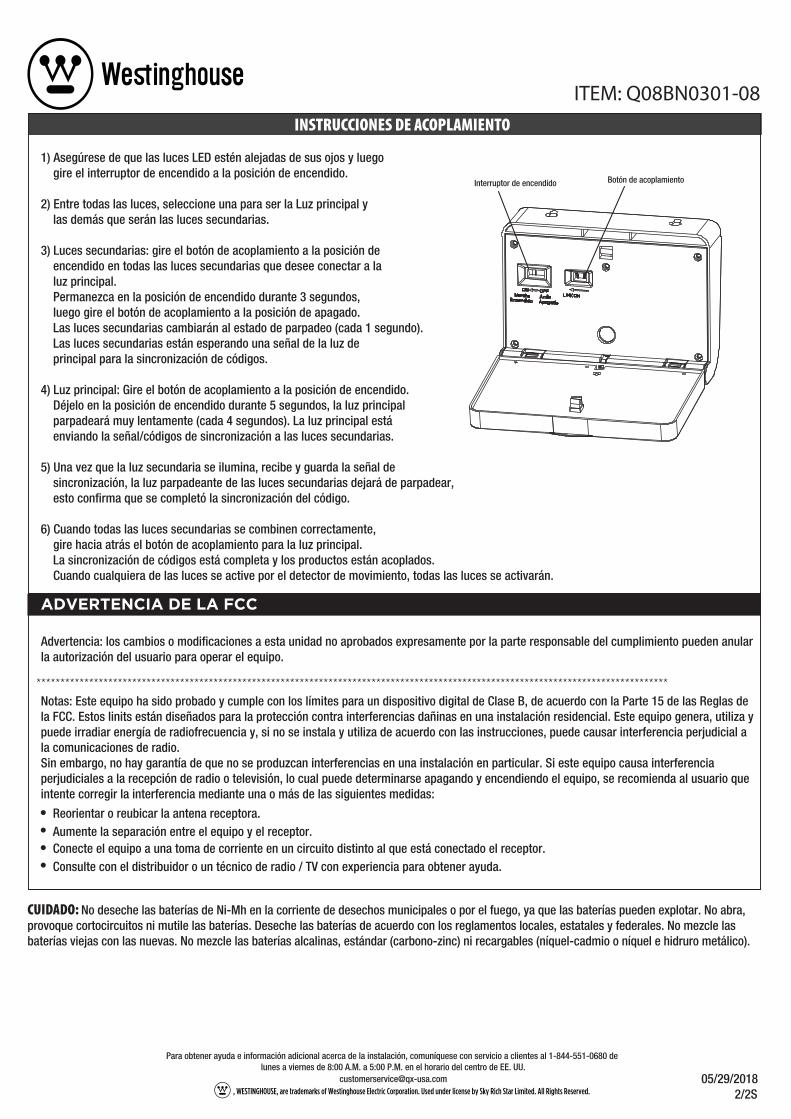
1) Asegúrese de que las luces LED estén alejadas de sus ojos y luego gire el interruptor de encendido a la posición de encendido.
2) Entre todas las luces, seleccione una para ser la Luz principal y las demás que serán las luces secundarias. 3) Luces secundarias: gire el botón de acoplamiento a la posición de encendido en todas las luces secundarias que desee conectar a la luz principal. Permanezca en la posición de encendido durante 3 segundos, luego gire el botón de acoplamiento a la posición de apagado. Las luces secundarias cambiarán al estado de parpadeo (cada 1 segundo). Las luces secundarias están esperando una señal de la luz de principal para la sincronización de códigos.
4) Luz principal: Gire el botón de acoplamiento a la posición de encendido. Déjelo en la posición de encendido durante 5 segundos, la luz principal parpadeará muy lentamente (cada 4 segundos). La luz principal está enviando la señal/códigos de sincronización a las luces secundarias. 5) Una vez que la luz secundaria se ilumina, recibe y guarda la señal de sincronización, la luz parpadeante de las luces secundarias dejará de parpadear, esto confirma que se completó la sincronización del código.
6) Cuando todas las luces secundarias se combinen correctamente, gire hacia atrás el botón de acoplamiento para la luz principal. La sincronización de códigos está completa y los productos están acoplados. Cuando cualquiera de las luces se active por el detector de movimiento, todas las luces se activarán.
Botón de acoplamientoInterruptor de encendido
INSTRUCCIONES DE ACOPLAMIENTO
ADVERTENCIA DE LA FCC
Reorientar o reubicar la antena receptora.Aumente la separación entre el equipo y el receptor.Conecte el equipo a una toma de corriente en un circuito distinto al que está conectado el receptor.Consulte con el distribuidor o un técnico de radio / TV con experiencia para obtener ayuda.
Advertencia: los cambios o modificaciones a esta unidad no aprobados expresamente por la parte responsable del cumplimiento pueden anular la autorización del usuario para operar el equipo.
Notas: Este equipo ha sido probado y cumple con los límites para un dispositivo digital de Clase B, de acuerdo con la Parte 15 de las Reglas de la FCC. Estos linits están diseñados para la protección contra interferencias dañinas en una instalación residencial. Este equipo genera, utiliza y puede irradiar energía de radiofrecuencia y, si no se instala y utiliza de acuerdo con las instrucciones, puede causar interferencia perjudicial a la comunicaciones de radio.Sin embargo, no hay garantía de que no se produzcan interferencias en una instalación en particular. Si este equipo causa interferencia perjudiciales a la recepción de radio o televisión, lo cual puede determinarse apagando y encendiendo el equipo, se recomienda al usuario que intente corregir la interferencia mediante una o más de las siguientes medidas: