Embed Size (px)
Citation preview

INSTRUCTIONSfor installation and use
GAS RANGE WITH OVEN FORRESIDENTIAL AND PROFESSIONAL USE
GEPS12MP


TABLE OF CONTENTS
WARNINGS & CAUTION............................................................................4
SAFETY INSTRUCTIONS .........................................................................5
BURNER ASSEMBLY DIAGRAM...............................................................6
INSTALLATION INTRUCTIONS...............................................................10
USE AND MAINTENANCE INSTRUCTIONS...........................................18
CLEANING AND CARE INSTRUCTIONS................................................21

4 Officine Gullo
WARNINGS & CAUTION
1. Before using the appliance, read the instruction manual carefully, as it contains important safety infor-
mation on the proper installation, use and maintenance of the appliance. Please keep the instruction
manual for further reference.
2. The appliance’s electrical safety is guaranteed only if the electrical system is grounded in accordance
with the relevant regulations. It is of the utmost importance to follow such regulations; when in doubt,
please consult a qualified electrician to have the electrical system thoroughly checked. The manufac-
turer declines all responsibility for damage caused by a improperly grounded electrical system
3. Before connecting the appliance, make sure that the appliance’s technical characteristics shown on
the tag correspond to those of the electrical system and gas supply.
4. Make sure that the electrical system and sockets can handle the appliance’s maximum power con-
sumption as shown on the tag. When in doubt, please consult a qualified electrician.
5. When not in use for extended periods, switch off the general power supply to the appliance and close
the gas supply valve.
6. Do not obstruct the appliance’s cooling or heat dissipation vents.
7. The appliance must be used only for the purposes for which it has been expressly designed (cooking).
All other uses (such as the heating of a room) are considered inappropriate and therefore dangerous.
The manufacturer declines all responsibility for damage resulting from improper use of the appliance.
8. The use of any electric appliance implies the observance of some basic rules. More specifically:
- Avoid the use of extension cords and, if necessary, take all precautions;
- Do not pull the power cord to disconnect the plug from the power socket;
- Do not allow children or untrained persons to use the appliance.
9. Before performing maintenance work, disconnect the appliance by pulling the plug out of the power
socket or turning off the main switch.
10. In case of failure or malfunction, turn the appliance off, close the gas supply valve and do not at-
tempt to carry out any repairs, which must be done exclusively by an authorized service center.
5Officine Gullo
SAFETY INSTRUCTIONS
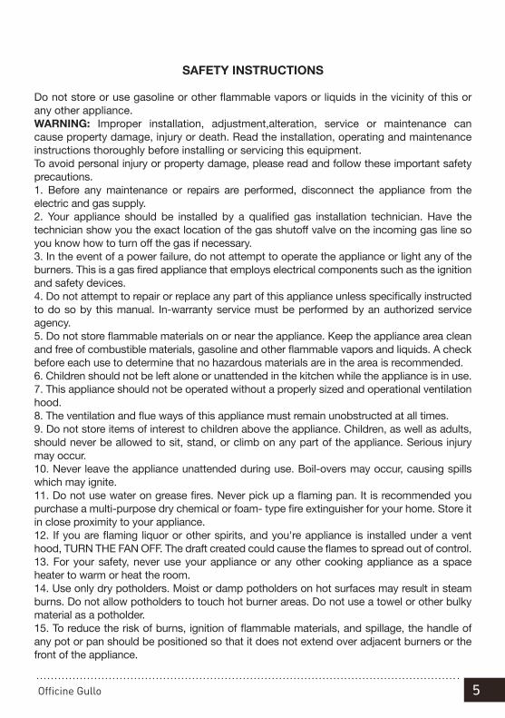
Do not store or use gasoline or other flammable vapors or liquids in the vicinity of this or any other appliance.WARNING: Improper installation, adjustment,alteration, service or maintenance can cause property damage, injury or death. Read the installation, operating and maintenance instructions thoroughly before installing or servicing this equipment.To avoid personal injury or property damage, please read and follow these important safety precautions.1. Before any maintenance or repairs are performed, disconnect the appliance from the electric and gas supply.2. Your appliance should be installed by a qualified gas installation technician. Have the technician show you the exact location of the gas shutoff valve on the incoming gas line so you know how to turn off the gas if necessary.3. In the event of a power failure, do not attempt to operate the appliance or light any of the burners. This is a gas fired appliance that employs electrical components such as the ignition and safety devices.4. Do not attempt to repair or replace any part of this appliance unless specifically instructed to do so by this manual. In-warranty service must be performed by an authorized service agency.5. Do not store flammable materials on or near the appliance. Keep the appliance area clean and free of combustible materials, gasoline and other flammable vapors and liquids. A check before each use to determine that no hazardous materials are in the area is recommended.6. Children should not be left alone or unattended in the kitchen while the appliance is in use.7. This appliance should not be operated without a properly sized and operational ventilation hood.8. The ventilation and flue ways of this appliance must remain unobstructed at all times.9. Do not store items of interest to children above the appliance. Children, as well as adults, should never be allowed to sit, stand, or climb on any part of the appliance. Serious injury may occur.10. Never leave the appliance unattended during use. Boil-overs may occur, causing spills which may ignite.11. Do not use water on grease fires. Never pick up a flaming pan. It is recommended you purchase a multi-purpose dry chemical or foam- type fire extinguisher for your home. Store it in close proximity to your appliance.12. If you are flaming liquor or other spirits, and you're appliance is installed under a vent hood, TURN THE FAN OFF. The draft created could cause the flames to spread out of control.13. For your safety, never use your appliance or any other cooking appliance as a space heater to warm or heat the room.14. Use only dry potholders. Moist or damp potholders on hot surfaces may result in steam burns. Do not allow potholders to touch hot burner areas. Do not use a towel or other bulky material as a potholder.15. To reduce the risk of burns, ignition of flammable materials, and spillage, the handle of any pot or pan should be positioned so that it does not extend over adjacent burners or the front of the appliance.

6 Officine Gullo
FIG.A
FIG.B
1. Injector cooking rings2. Air regulation
3. Lighting spark plug4. Thermocouple
3
FIG. D
1 By-pass fuochi aperti Bypass flamme By-pass feux Cooking rings by-pass By-pass fuegos 2 By-pass forno Backofen Bypass By-pass four Oven by-pass By-pass horno
FIG. F PC…-GP , CF…-GP (FUOCHI, FLAMME, FEUX, COOKING RINGS, FUEGOS)
562047300M00P00
1
2
3
4
1 Iniettore fuochi Einspritzventil flamme Injecteur feux Injector cooking rings Inyector fuegos 2 Regolazione aria Luftregelung Réglage d'air Air regulation Regulación aire 3 Candela accensione Zündkerze Bougie d'allumage Lighting spark plug Candela encendido 4 Termocoppia Thermoelement Thermocouple Thermocouple Termopar
1. Cooking rings by-pass

7Officine Gullo
FIG.C
1. Injector2. Pilot
COUP DE FEU

8 Officine Gullo
ELECTRICAL SCHEME TOP
1. Electrical connection2. Push-button starting burner3/4. Power-station starting burner
FIG. D
ELECTRICAL / SCHEME
The installation of this appliance must conform with all applicable local codes. In the absence of local codes, the installation must conform to the latest level of the National Electric Code, ANSI/NFPA 70.If the electrical supply is not turned on or is interrupted the appliance will not operate. The applicable wiring diagram for this appliance is below. The circuit where you wire your appliance to must be grounded and polarized. We recommend the circuit for your appliance be a non-GCFI dedicated line.

9Officine Gullo
OVEN ELECTRICAL SCHEMEFIG.E
LIBR.ALLEG.CF70GE 230Vac 230Vac3 563035700.doc
SCHEMA ELETTRICO , SCHALTPLAN, SCHEMA ELECTRIQUE , WIRING DIAGRAM, ESQUEMA ELECTRICO
GN 2/1 549018805 M00_00
230V~ 50/60Hz 230V~3 50/60Hz
1-2 Commutatore Schalter Commutateur Commutator Conmutador
3 Morsettiera Klemm-leiste Bornier Junction-box Tablero de bornes
4 Resistenza Widerstand Résistance Element Resistencia
5 Spia bianca weiße Kontroll-Leuchte Témoin blanc White light Luz indicadora blanca
6 Spia verde grüne Kontroll-Leuchte Témoin vert Green light Luz indicadora verde
7 Termostato sicurezza Sicherheits-thermostat Thermostat de sécurité Safety thermostat Termostato de seguridad
8 Termostato Thermostat Thermostat Thermostat Termostato
1. Commutator2. Commutator3. Junction-box4. Element5. White light6. Green light7. Safety thermostat8. Thermostat

10 Officine Gullo
INSTALLATION INSTRUCTIONS
This appliance is manufactured by OFFICINE GULLO S.r.lHeadquarters and factory50012 Antella - Bagno a Ripoli (FI) Italyvia della Torricella, 29, tel. +39 055 6560324 In the US call (800)-781-7125
Home page http:// www.officinegullousa.comE-Mail: [email protected]
INSTALLATION’S MANUALKeep the appliance area free and clear from combustibles.Not obstruct the flow of combustion and ventilation air,This manual shall be retained for future reference.
The manufacturer declines any responsibility for direct or indirect damage caused by impro-per or incorrect installation, alterations, maintenance or use of the appliance, as in all the other cases considered in the items of our sales conditions.
For assembly proceed as follows:• To screw to held the elbow to 90°(1) on the ramp of income of gas.• To screw the elbow the nipples of the connexion (2).• To screw the nipple to the pressure regulator (3).WARNING: Maximum input pressure is ½ PSI.The pressure regulator has to be placed under or behind the cabinetry next to the range or in a different place but never under or behind it.
GAS PRESSURE REGULATOR (Must be installed)
Each gas hook input (every element) is supplied with a separate pressure regulator that needs to be installed.

11Officine Gullo
INSTALLATION’S INSTRUCTIONS
GAS CONNECTIONS
This appliance must be installed by an approved installer or a gas technician
1. The installation of this appliance must conform with all applicable local codes. In the absence of local codes, the installation must conform to the latest level of the National Fuel Gas Code, ANSI Z223.1/NFPA 54. In Canada, the installation must be in accordance with the current CAN/CGA B149.1 and B149.2. 2. This appliance can be configured to work with either natural gas or LP gas. Verify that the appliance and the incoming gas supply are compatible. Check the rating plate. 3. The gas supply line must be the same size or larger than the gas inlet of the appliance. Your appliance has ¾” NPT gas inlet connection at the factory supplied gas regulator for each gas input. We recommend the supply line be ¼” NPT larger than the gas inlet of the appliance. 4. Sealant used on pipe joints must be resistant to LP gas. 5. An installer provided manual shut-off valve must be installed in the gas supply line ahead of the appliance. This shut-off must be easily accessible in case of emergency. 6. All gas cooking equipment must have a pressure regulator on the incoming service line for safe and efficient operation. This appliance is equipped with such a gas pressure regulator. Incoming gas pressure should be checked with a manometer. The correct manifold pressure for natural gas is 5.0” wc. For LP gas the correct manifold pressure is 10” wc. 7. Incoming line pressure upstream of the appliance should be 1.0” wc greater than the operating manifold pressure. Service pressure may fluctuate for a variety of reasons. Under no circumstances should the factory supplied regulator be removed or by-passed. 8. The factory supplied pressure regulator will withstand an input pressure of ½ PSI (12” wc). If the incoming pressure exceeds the maximum rating, a step-down regulator is required. 9. The appliance and its individual shut-off valve must be disconnected from the gas supply line during any pressure testing in excess of ½ PSI [3.5 kPa]. 10. The appliance must be disconnected from the gas supply by closing its individual shut-off during any pressure testing less than ½ PSI [3.5 kPa]. 11. Check to see that all installer supplied pipes and fittings are clear of debris, threading chips or other foreign particles before connecting the appliance to the supply line. Such particles will clog orifices and/or valves when pressure is applied. Service to clean such clogs is not covered by your warranty.12. The incoming gas supply is brought from the inlet pipe. This is the only connection required via the installer-supplied shut-off valve. 13. If the appliance is to be installed with flexible couplings and/or a “quick disconnect” the installer must use a commercially approved AGA Design certified flexible connector at least ½” NPT that complies with ANSI Z21.41. In Canada, the connector must comply with CAN 16.10-88 and the “quick disconnect” device must comply with CAN 16.19M-79 and

12 Officine Gullo
installed with a strain relief device. 14. Before putting the appliance into service test all gas connections for leaks. Use a soapy solution. DO NOT USE AN OPEN FLAME TO CHECK FOR LEAKS. Such a procedure is dangerous, and it may not detect all the small leaks that a soapy solution will15. Air shutter adjustments are preset at the factory. These adjustments may need to be redone and/or fine tuned by the installer.
UNPACKING• Cut and Remove Plastic Straps• Lift off cardboard surround• Lift equipment off Timber standThe machine is supplied with pressure regulator separately (in 3/4 NPT F)
INSTALLATION• The appliance must be installed in accordance with the ANS Z83.11a CSA 1.8a(2001)
Food Service Equipment.• The operations for installing, conversions for use with other types of gas and starting
up must be done only by qualified personnel whose qualifications comply with the norms in force.
• Gas installations, the electrical connections and the rooms in which the appliances are installed must comply with the norms in force in the Country in which the installation is carried out; above all, the appliance must be installed in a well ventilated room, prefera-bly under an extractor hood, so as to ensure the complete extraction of gas emissions which are formed during combustion. The air necessary for combustion is 70.6 CbtF /h per 3412 BTu's (2m3 /h per kW) of power installed.
TECHNICAL GAS DATA TABLE
MODELDIMENSIONS
cm
NOMINAL BURNER CAPACITY TOT.NOM. CAPACITY
GasBTU/h
Gascoupling
NPT
Coup de feu
23,885BTU/h
Nr. Open ring
11,942BTU/h
Nr. Open ring
18,767BTU/h
Nr. Open ring
25,591BTU/h
GEPS12P120x70x90h
1 1 2 1 98,952 3/4GM
The machine is supplied with pressure regulator separately (in 3/4 NPT F)
TECHNICAL ELECTRICAL DATA TABLE
MODELDimensions
cmTotkW
Max. Assorb.
APower supply
Power supply
cable mm²
GEPS12P 120x70x90h 5 21,74110+110V 50/60 Hz
3 x 2,5
13Officine Gullo
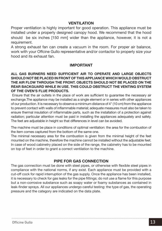
VENTILATIONProper ventilation is highly important for good operation. This appliance must be installed under a properly designed canopy hood. We recommend that the hood should be six inches [150 mm] wider than the appliance, however, it is not a requirement.A strong exhaust fan can create a vacuum in the room. For proper air balance, work with your Offcine Gullo representative and/or contactor to properly size your hood and its exhaust fan.
IMPORTANT
ALL GAS BURNERS NEED SUFFICIENT AIR TO OPERATE AND LARGE OBJECTS SHOULD NOT BE PLACED IN FRONT OF THIS APPLIANCE WHICH WOULD OBSTRUCT THE AIR FLOW THROUGH THE FRONT. OBJECTS SHOULD NOT BE PLACED ON THE REAR BACKGUARD WHILE IN USE. THIS COULD OBSTRUCT THE VENTING SYSTEM OF THE OVEN’S FLUE PRODUCTS. Ensure that the air outlets in the place of work are sufficient to guarantee the necessary air exchange.The appliance may be installed as a single element or in series with other appliances of our production. It is necessary to observe a minimum distance of 4" (10 cm) from the appliance to prevent contact with walls of inflammable material; adequate measures must also be taken to ensure thermal insulation of inflammable parts, such as the installation of a protection against radiation; particular attention must be paid in installing the appliances adequately and safely. The feet are adjustable in height so that differences in level can be avoided.
The machine must be place in conditions of optimal ventilation: the area for the combustion of the item comes captured from the bottom of the same one.The minimal necessary area for the combustion is given from the minimal height of the feet mounted on the machine, therefore the machine cannot be installed without the adjustable feet.In case of wood cabinetry placed on the side of the range, the cabinetry has to be mounted on top of feet in order to grant a correct ventilation to the machine.
PIPE FOR GAS CONNECTIONThe gas connection must be done with steel pipes, or otherwise with flexible steel pipes in compliance with the national norms, if any exist. Each appliance must be provided with a cut-off cock for rapid interruption of the gas supply. Once the appliance has been installed, it is necessary to check for gas leaks for the pipe fittings; do not use a flame for this purpose but a non-corrosive substance such as soapy water or foamy substances as contained in leak-finder sprays. All our appliances undergo careful testing: the type of gas, the operating pressure and the category are indicated on the data plate.
14 Officine Gullo
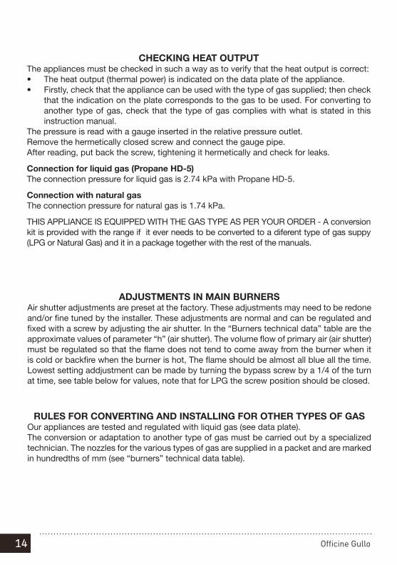
CHECKING HEAT OUTPUTThe appliances must be checked in such a way as to verify that the heat output is correct:• The heat output (thermal power) is indicated on the data plate of the appliance.• Firstly, check that the appliance can be used with the type of gas supplied; then check
that the indication on the plate corresponds to the gas to be used. For converting to another type of gas, check that the type of gas complies with what is stated in this instruction manual.
The pressure is read with a gauge inserted in the relative pressure outlet.Remove the hermetically closed screw and connect the gauge pipe.After reading, put back the screw, tightening it hermetically and check for leaks.
Connection for liquid gas (Propane HD-5)The connection pressure for liquid gas is 2.74 kPa with Propane HD-5.
Connection with natural gas The connection pressure for natural gas is 1.74 kPa.
THIS APPLIANCE IS EQUIPPED WITH THE GAS TYPE AS PER YOUR ORDER - A conversion kit is provided with the range if it ever needs to be converted to a diferent type of gas suppy (LPG or Natural Gas) and it in a package together with the rest of the manuals.
ADJUSTMENTS IN MAIN BURNERSAir shutter adjustments are preset at the factory. These adjustments may need to be redone and/or fine tuned by the installer. These adjustments are normal and can be regulated and fixed with a screw by adjusting the air shutter. In the “Burners technical data” table are the approximate values of parameter “h” (air shutter). The volume flow of primary air (air shutter) must be regulated so that the flame does not tend to come away from the burner when it is cold or backfire when the burner is hot, The flame should be almost all blue all the time. Lowest setting addjustment can be made by turning the bypass screw by a 1/4 of the turn at time, see table below for values, note that for LPG the screw position should be closed.
RULES FOR CONVERTING AND INSTALLING FOR OTHER TYPES OF GASOur appliances are tested and regulated with liquid gas (see data plate).The conversion or adaptation to another type of gas must be carried out by a specialized technician. The nozzles for the various types of gas are supplied in a packet and are marked in hundredths of mm (see “burners” technical data table).
GAS A (Natural gas)
BurnerNominal GasConsumption
(BTU/h)
Main Injector size
Nominal/(Measured)Values in mm
Lowest setting addjustment (By-pass Screw
Adjustment) (See note)
Air Shutter Adjustment
(Primary AerationAdjustment)
Values in mm
Small 11,942 1.60 ¼ turn Fully open
Medium 18,767 1.90 ¼ turn 33
Large 25,591 2.40 ¼ turn 35
Coup de Feu
23,885 1.45 ¼ turn -
GAS E (Propane gas)
BurnerNominal GasConsumption
(BTU/h)
Main Injector size
Nominal/(Measured)Values in mm
Lowest setting addjustment (By-pass Screw
Adjustment)(See note)
Air Shutter Adjustment
(Primary AerationAdjustment)
Values in mm
Small 11,942 1.00 0.20 Fully open
Medium 18,767 1.15 Fully closed Fully open
Large 25,591 1.45 Fully closed 20
Coup de Feu
23,885 1.45 Fully closed -

15Officine Gullo
GAS A = Natural gas (pressure at the outlet of the regulator) = 10 mbar (4 inch water)GAS E = Propan gas (pressure at the outlet of the regulator) = 24.9 mbar (10 inch water)
“BURNERS” TECHNICAL DATA TABLE & ADJUSTMENT VALUES
GAS A (Natural gas)
BurnerNominal GasConsumption
(BTU/h)
Main Injector size
Nominal/(Measured)Values in mm
Lowest setting addjustment (By-pass Screw
Adjustment) (See note)
Air Shutter Adjustment
(Primary AerationAdjustment)
Values in mm
Small 11,942 1.60 ¼ turn Fully open
Medium 18,767 1.90 ¼ turn 33
Large 25,591 2.40 ¼ turn 35
Coup de Feu
23,885 1.45 ¼ turn -
GAS E (Propane gas)
BurnerNominal GasConsumption
(BTU/h)
Main Injector size
Nominal/(Measured)Values in mm
Lowest setting addjustment (By-pass Screw
Adjustment)(See note)
Air Shutter Adjustment
(Primary AerationAdjustment)
Values in mm
Small 11,942 1.00 0.20 Fully open
Medium 18,767 1.15 Fully closed Fully open
Large 25,591 1.45 Fully closed 20
Coup de Feu
23,885 1.45 Fully closed -

16 Officine Gullo
REPLACING THE NOZZLE FOR THE BURNERSMain nozzles:Remove the grills, the burners and the containers, substitute the nozzles with the right ones, using a suitable spanner, unscrewing the blockage screw and relative jam nut. Once regulated, tighten the screw, adjust the minimum flame by turning the screw to the right or left until the thermal power reaches 3,924 BTU/h for the 11,942 BTU/h burner, 35,290 BTU/h for the 18,767 BTU/h burner and 8,530 BTU/h for the 25,591 BTU/h burner.Warning: For functioning with LPG, the screw for regulating minimum output must be blocked completely.
SUBSTITUTING THE NOZZLE IN THE ALL PLATE BURNERRemove the panel and with a suitable spanner substitute the nozzle with another, suitable one.Adjust the minimum flame by turning the by-pass screw either to the right or to the left until heat output reaches 13,648 BTU/h.The primary air of the all plate burner does not need adjusting.Warning: For functioning with LPG, the screw for regulating minimum output must be blocked completely.
DECLARATION OF COMPLIANCEThe manufacturer declares that the appliances are compliant with the prescriptions of the EEC norm 90/396 for the gas part and with norm 73/23 for the electric part. The installation must be done observing the norms in force particularly concerning room ventilation and discharging gas emissions.N.B.: The manufacturer declines any responsibility for direct or indirect damage caused by improper or incorrect installation, maintenance or use of the appliance and alterations, as in all the other cases considered in the items of our sales conditions.

17Officine Gullo
Picture 2E
ELECTRIC CONNECTIONThe appliance is supplied without the connection cable; to install it, proceed in the fol-lowing way:-Remove the back panel bye removing the screws that are around its perimeter as shown in picture 1E -Fit the connection cable through the cable channel, connect the conductor wires to the corresponding terminals in the junction box as shown in picture 2E below and fix them into place.-Block the cable with the cable blocker, and reassemble the panel. The ground wire must be longer than the others so that if the cable blocker should break for any reason, it will disconnect after the hot wires.N.B. The connection cable must have the following characteristics: it must be type H05RN-F and must have an adequate section for the power of the appliance (see technical data table).The installation of this appliance must conform with all applicable local codes. In the absence of local codes, the installation must conform to the latest level of the National Electric Code, ANSI/NFPA 70.
There are several screws around the perimeter of the back panel, to remove the panel you need to remove all the screws around the perimeter and them pull away the panel to access the terminal block. IMPORTANT ! MAKE SURE TO ALWAYS DISCONNECT THE APPLIANCE FROM THE ELECTRICITY BEFORE WORKING ON IT.
Picture 1E
L1L2N
Line
110
/ 120
V
Line
110
/ 120
V

18 Officine Gullo
USE AND MAINTENANCE INSTRUCTIONS
INSTRUCTIONS FOR USEAttention! The appliance must only be used under surveillance.
LIGHTING AND ADJUSTING THE BURNERS
On the front panel, above each knob, there is a symbol which indicates to which burner the knob corresponds. To light, turn the knob to the left from position “0” to the symbol (see figure); keep it pushed down and press the button with the symbol until the gas lights.The knob must be kept pushed down for a few seconds and then released. The flame may go out, in which case it is necessary to repeat the procedure. By turning to the position, the burner is brought to the minimum. To put out the burner, turn the knob back into the “0” position.
LIGHTING AND ADJUSTING THE COUP DE FEU
On the front panel, above each knob, the burner it corresponds to is indicated by the index Use a lighter to light the pilot flame: turn the knob to the left, from the “0” position to the sign (see figure), hold it down and light the gas.Keep the knob pressed a few second and then let it go.If the flame goes out you have to repeat the procedure.By turning the knob round to the position the burner is at maximum.By turning the knob round to the position the burner is at minimum. To switch off, move the knob back into position " 0".

19Officine Gullo
TURNING ON AND ADJUSTING THE ELECTRIC OVEN
Turn the control knob to the right and set the temperature wanted.To turn the oven off, turn the knob to the left to position 0.To turn the oven on, turn the selector knob (see figure) to the right or left into one of the following positions.
Top + bottom heating element
Bottom heating element
Top heating element
Caution: when the oven is on the door must be kept shut other-wise the knobs and protection sheet could get hot and be dama-ged.
0 570 480 390 300 210
1
20

20 Officine Gullo
VERY IMPORTANT
With the use of the range the brass (burnished, nickel or chrome) plate, show in the picture, may warp due to the developed heat. After the use the bar will get it's original shape.

21Officine Gullo
CARE AND CLEANING INSTRUCTIONS
CLEANING BURNISHED BRASS SURFACESNo synthetic protective varnishes have been used to obtain the special burnishing effect on the burnished brass details in order to avoid spoiling the beauty of the brass with an artificial patina. The antique finish of the surface is the result of natural oxidation that has simply been accelerated. All the natural antique finish brass surfaces can be cleaned with mild soap and warm water, accompanied by the use of an abrasive pad (the green color type used for washing dishes). It is recommended that the metal be rubbed, uniformly applying light pressure, use caution as this will remove some of the patina if rubbed excessvily. The brass details should then be dried. Do not use metal polish as this is suitable not to clean the antique finish and could result in loos of the color and patina. Oxidation that may appear over time on the burnished brass surfaces is a normal characteristic of our craft metal working processes.
CLEANING CHROME PLATED BRASS SURFACESNo synthetic varnishes have been used to obtain the special polish on the chromium-plated brass details in order to avoid spoiling the beauty of the chrome with an artificial patina. All the chromed surfaces should be clean as needed with a warm water and mild soap and a soft cloth or micro-fiber. Do not use abrasive pads.
CLEANING SATIN FINISH NICKEL PLATED BRASS SURFACESNo synthetic varnishes have been used to obtain the special nickel-plating on the satin finish nickel-plated brass details in order to avoid spoiling the beauty of the nickel-plated, satin finished solid brass with an artificial patina. All the nickel-plated and satin finished brass surfaces should be cleaned, where necessary, with a soft cloth or micro-fiber cloth, combined with a mild soap, if required. Do not use abrasive pads.
CLEANING THE VARNISHED SURFACESAll the varnished surfaces should be cleaned using a mild soap and, where necessary, a soft cloth or micro-fiber cloth. Do not use abrasive pads or any other chemical products.

22 Officine Gullo
CLEANING BRUSHED STEEL SURFACESAll the brushed steel surfaces should be cleaned using degreasing products or products specifically designed to be used on steel and, where necessary, extra-fine steel wool.
WHAT TO DO IN THE EVENT OF A BREAKDOWNTurn off the gas shut off valve and notify your authorized service center or call our main line at (800) 781-7125

23Officine Gullo

WWW.OFFICINEGULLO.COM
V 1.3 - 10.17
OFFICINE GULLO S.R.L.: via della Torricella 29, 50012 Antella - Bagno a Ripoli (FI)
Tel. +39 055 6560324 / 621807 - Fax: + 39 055 620670 - [email protected]
us