Embed Size (px)
Citation preview
122223334679910111112131314151516171820
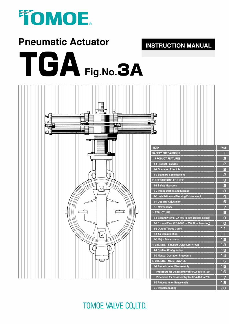
Fig.No.3ATGAPneumatic Actuator INSTRUCTION MANUAL
PAGEINDEX
SAFETY PRECAUTIONS
1. PRODUCT FEATURES
1-1 Product Features
1-2 Operation Principle
1-3 Standard Specifications
2. PRECAUTIONS FOR USE
2-1 Safety Measures
2-2 Transportation and Storage
2-3 Installation and Working Environment
2-4 Use and Adjustment
2-5 Maintenance
3. STRUCTURE
3-1 Expand View (TGA-100 to 160: Double-acting)
3-2 Expand View (TGA-180 to 250: Double-acting)
3-3 Output Torque Curve
3-4 Air Consumption
3-5 Major Dimensions
4. CYLINDER SYSTEM CONFIGURATION
4-1 System Configuration
4-2 Manual Operation Procedure
5. CYLINDER MAINTENANCE
5-1 Procedure for Disassembly
Procedure for Disassembly for TGA-100 to 160
Procedure for Disassembly for TGA-180 to 250
5-2 Procedure for Reassembly
5-3 Troubleshooting
Cat.No.EG003-⑤ 2013.04.24-Pn
◎ The specifications are subject to change without notice.Please consult us for the latest specifications.◎ All copy rights reserved.
www.tomoevalve.comwww.tomoevalve.com
www.tomoeeurope.co.ukwww.tomoeeurope.co.uk
●Head Office3-11-11 Shinmachi, Nishi-ku, Osaka 550-0013, JapanTelephone: +81-6-6110-2101/2102/2103 Telefax: +81-6-6110-2105/2106 E-mail:[email protected]
Clearwater Road, Queensway Meadows Industrial Estate,Newport, South Wales NP19 4ST, United KingdomTelephone: +44-1633-636800 Telefax: +44-1633-636801 E-mail:[email protected] [email protected]
600, Rockmead Drive Suite 115,Kingwood, Houston Texas, 77339, USATelephone: +1-281-358-7571/7859 Telefax: +1-281-358-7861
Blk 8 Chia Ping Road #07-11 Singapore 619973Telephone: +65-68995060 Telefax: +65-68995061 E-mail:[email protected]
Global Sales Operations
No.2755 Bao An Road,Malu Town,Jiading District Shanghai,201801.CHINA.Telephone: +86-21-69155067 Telefax: +86-21-69155068
www.tomoe.com.sg/index.phpwww.tomoe.com.sg/index.php
A1
A2B1
B2
This product is a double-acting pneumatic actuator suitable for ON-OFF control of various butterfly valves, and can be used to control valves with a medium/large bore diameter of large of 350 mm or more. Also, the TGA cylinder can optionally be applied to flow rate control in combination with positioner.The product permits the piston to be put in linear reciprocating motion using air pressure, causing the trunnion coupled with the rod to rotate the output shaft repeatedly through the arm.
1. PRODUCT FEATURES
As chambers A1 and A2 or B1 and B2 are connected through copper tubes as shown in the figure at left (single-acting cylinder is provided only with chambers A2 and B1), feeding air to port “S” moves the piston to left, in which thrust is transmitted to the trunnion on the piston rod to give the output shaft a force to produce clockwise rotation through the arm, rotating the shaft clockwise. Residual air in chamber B is exhausted through port “O”. Feeding air to port “O” causes the reverse of the above-mentioned action, rotating the output shaft counterclockwise.
TGA-100
585
TGA-125
1069
TGA-140
1510
TGA-160
2274
TGA-180
3194
TGA-200
4339
TGA-220
5977
TGA-250
8620
Rc3/8 Rc1/2Rc1/4
※1 If used for the TRITEC with over 0.5MPa supply pressure, please ask us about cylinder specifications.※2 Please consult with our sales department when used at working temperature of more than 60 degrees C as the cylinder can be changed.
Note that the items listed here are to promote the correct usage of TGA actuator (hereinafter "this product") and to help prevent injury or damage.Carefully read this instruction manual in its entirety then proceed to use the product correctly while adhering to the safety precautions.Furthermore, please be sure to also read the safety precautions for handling valves.
Please Observe the Following Safety Precautions
■The degrees of danger and damage that may occur when displayed advisories are ignored and the product is used incorrectly are classified and described below.
■What types of advisories are to be observed are classified and indicated below. (Below are examples of symbols.)
WARNING!This display denotes that death or serious injury may occur.
This symbol indicates that the following content is "Prohibited".
This symbol indicates that the following content is "Compulsory".
This display denotes that injury or only property damage may occur.
CAUTION!
■Request●Carefully read this instruction manual before transporting, storing, attaching pipes, operating, or
performing maintenance.
●This instruction manual was not written with the assumption of all situations with regard to
transportation, storage, piping attachment, operation, and maintenance of this product; if there are any
unclear points, please do not hesitate to contact our sales representative.
●Standard and limit values of operations, maintenance, and inspection specified in this instruction manual
were set with consideration for maintenance management of this product. Please operate in compliance
with the reference value (standard value) and limit value.
●Use this product by connecting only to a valve with open-close angle of 90 degrees or below.
●Be sure to store this instruction manual in a readily accessible place for future reference after
installation and operation start. If staff in charge is changed, information on the storage place of the
instruction manual and operation should be transferred to the next staff.
●If dents or scratches are made due to shock, stop using the product for safety and replace the product.
*The contents of this instruction manual are subject to change without notice.
1-2 Operation Principle
1-1 Product Features
1-3 Standard Specifications
Arm
Trunnion
Port “O”Port “S”
Output shaft
Piston Rod
Piston
Torque (N・m) (0.4MPa)
Supply pressure (MPa)
Body shell max (MPa)
Port size
Rotating angle
Operating fluid
Working temperature range/Supplied Air Temperature Range
Rotating speed range (sec.)
Coating
0.4~0.7 ※1
1.0
0゚~+90゚Dry air
0 to 80 degrees C / 0 to 60 degrees C(Without Frost Air)※2
5 to 15
Epoxy primer finish (Munsell N7)
1 2
2. PRECAUTIONS FOR USE
2.1.1 Handling This ProductEnsure that only personnel with sufficient knowledge and experience handle this product.Compressed air can be dangerous if dealt with improperly. Ensure that only personnel who have carefully read the instruction manual (hereinafter "this document") and understand the contents well, assemble, operate, maintain, etc. machines and equipment that utilize pneumatic equipment.
2.1.2 Confirming Safe ConditionsNever attempt to handle machines or equipment, or remove machinery before safety is ensured.When removing machinery, confirm the following items and ensure safety.(1) Safety precautions for this product, such as preventions against falling of parts, material or other
accidental happenings, have been taken.(2) The surface temperature of this product is a temperature where the surface can be touched.(3) Supply air, etc. that is the energy source and compressed air in the air piping system have been
removed.(4) No fluid flows in the pipelines.(5) The power of the system has been shut off.
Confirm the following items before restarting the equipment.(1) This product is fixed to a valve securely.(2) There is no failure or damage on the appearance of this product, or loss of parts.(3) Tools have not been left on this product. (4) Nothing hinders operation of this product (operation of the cylinder, opening/closing of the valve).(5) There is no leakage of electrical and pneumatic signals.(6) There is no leakage of compressed air, etc.
2.1.3 Fail-safe DesignWhen using the unit for the point where fail-safe design is required, adopt a method where the system responds in a way that will cause no harm using a single-acting cylinder (spring back cylinder), a lock-up valve, etc. in the event of loss of all or a part of power that controls the machine.
2.1.4 Water HammerDesign should be performed in consideration of water hammer. Water hammer may occur even within the open-close time in the range of the product specifications, depending on the pipeline conditions or valve operating conditions.
2.2.1 MassProducts with greater weight (approx. 20 kg) cannot be moved by human power alone, and will require tools and machines to transport. Please confirm a product's mass in our catalog or by checking a product drawing. Forklifts, cranes and slinging must be operated and performed by certified workers, and please be sure follow laws and regulations, as well as your business' safety codes.
2.2.2 DroppingHandle the product properly when loading/unloading and double handling to prevent damage from dropping.
2.2.3 Dust Prevention, Water-proofingDo not remove the plug (tentative seal plug) connected to the piping connection until air piping work is to commence. If dust-prevention and water-proofing measures are not taken, rubbish, particles, rainwater, etc. enter this product, which causes malfunction. If the plug is lost, please cover the connection, use protection tape, or perform any similar protective measures. For single-acting cylinders, orient the exhaust port's elbow downwards to prevent rubbish, particles, rainwater, etc. from penetrating it.
2.3.1 Obtaining Space for Installation SiteFor installation sites, obtain work space around this product. If work space cannot be obtained, parts may not be removed at maintenance.
2.3.2 Installation Sites and Working EnvironmentIf installing at a site or working environment that requires special support for functional specification compliance, regulatory compliance, etc. – as noted in the following – please contact our sales representative before adopting usage of this product on any unclear points.(1) When there is a unique working environment that is not listed in the specifications.(2) When great risk to personnel, property, or the environment are predicted in the event of product failure.e.g.: Facilities related to High Pressure Gas Safety Act, facilities related to Industrial Safety and Health Act, Nuclear power related facilities, vehicles, medical facilities, etc.
2.3.3 Atmosphere of Installation SiteTake following measures depending on the atmosphere of the site where this product will be installed.(1) Avoid installation at sites that may expose this product to gas containing salt, corrosive gas, chemical
fluids, organic solvents and vapor. However, there are certain environmental conditions where corrosion prevention is possible; if this case applies, please contact our sales representative.
(2) If there is a possibility of direct exposure to radiant heat or chemicals, ensure protection of the product and ancillary devices by covering it.
(3) When installing a single-acting cylinder outdoors or at a site where it may be exposed to water, ensure that the exhaust port's elbow is facing down to prevent rubbish, particles, rainwater, etc. from penetrating it.
(4) This product should not be submerged.
2.3.4 Temperature of Installation SiteTake the following measures depending on the temperature of the site where this product is installed.Using the product out of the specified temperature range causes thermal degradation or hardening of the O-ring, as well as cause malfunction by difference of thermal expansion or thermal shrinkage of components.(1) The ambient temperature of the installation site should be based on the specifications.(2) The supplied compressed air, etc. should be based on the specifications.(3) If the product is exposed to direct sunlight, the working temperatures of this product and ancillary
devices should not exceed the upper limit.(4) Keep this product away from heat sources, and install in a site where the temperature is within the
specified temperature range. Particularly, ambient temperature may exceed the specified temperature range near a motor, an air compressor, etc.
(5) Use the ancillary devices within the appropriate temperature range of the ancillary devices.
2.2.4 StoragePlease follow the storage guidelines below to avoid contamination, discoloration, and material degradation of this product.(1) Do not store in high heat, high humidity places. Store in places without dust particles and moisture away
from direct sunlight.(2) Keep this product in the factory packaging, or utilize similar protective measures.(3) After one year in storage, it is necessary to inspect the product's operating condition, and if any
abnormalities are discovered it will be necessary to disassemble and inspect, then exchange any warped or degraded parts.
2-3 Installation and Working Environment
2-2 Transportation and Storage
2-1 Safety Measures
WARNING!
WARNING!
CAUTION!
CAUTION!
CAUTION!
3 4
2.3.5 Vibration and Shock at Installation SiteTake the following measures if there is vibration or shock at the site where this product is installed.(1) If this product is to be used under the following conditions, confirm vibration and shock conditions
(particularly the acceleration value) then contact our sales representative for consultation.1) In sites where excessive vibration or shock is exerted2) In sites where vibration or shock is exerted continuously
(2) Ensure that locks are applied to the product's attachments and connectors, and are securely fastened. This is important especially when opening/closing in high-frequency, and to consider fatigue resistance and fasten accordingly.
(3) Take vibration isolation measures to reduce vibration or shock on the machine. Pipelines should be fixed with supports, or vibration isolation material should be installed.
(4) It is important to conduct periodic inspections of fasteners to ensure that no loosening or warping has occurred, and make sure to tighten bolts or replace parts in the event of abnormal conditions. If the fastening bolts are removed, this product may drop off or actuate in an unexpected direction.
2.3.6 This Product and Valve Attachments DesignConfirm the following items when attachments between a valve and this product are designed.(1) No thrust load and lateral load has jointed to the product's output shaft.(2) To prevent axial movement of the valve stem on the valve from occurring, install an independent
stopper. If the output shaft of this product is used as a stopper for the valve stem of the valve, the valve stem may eject out due to fluid pressure when this product is removed.
(3) Secure adequate dimension to fit the output shaft of this product and the valve stem of the valve. Please refer to separate dimensional outline drawings for appropriate fit dimension. If the fit dimension is inadequate, strength at fitting section may become insufficient, resulting in damage.
2.3.7 Precautions at Air PipingConnect air pipes to this product while paying attention to the following items. If dents or scratches are made due to shock, stop using the product for safety and replace the product.(1) Make sure that strong force, impact from objects, or any sort of shock is not applied to the cylinder,
ancillary devices, or air pipes. Rough handling may result in warping of the output shaft or damage to the O-ring, which in turn causes air leaks.
(2) Avoid standing on this product at connecting pipelines. Do not insert this product by hitting it.(3) Prior to piping, air blow (flushing) or sufficiently clean pipes and joints; purge shavings, cutting oil,
rubbish, etc. within the pipes. It is especially important to ensure there are no accumulated piping screw shavings, cutting oil, rubbish, etc. in the secondary side of the air filter for compressed air, etc.
(4) When screwing pipes or joints, make sure shavings and sealant do not enter the interior of the product.(5) When the joints are screwed into the unit, excessive force may cause damage. After screwing in the
joints lightly, tighten the joints 1/4 turn as a guide. The reference value of the tightening torque is approx. 10 - 14 Nm.
(6) A plug (tentative seal plug) has been attached to the pipe connection and/or intake/exhaust at the factory to prevent foreign substances from entering. Please remove before using the product.
2.3.8 Precautions for Ancillary DevicesConfirm the following items on ancillary devices of this product.(1) In the factory state, the speed controller, which is a standard feature of the product, is set to full open.
Please rotate towards "close" (clockwise), and adjust the open-close time before using.(2) Rotation speed can be adjusted with the speed controller; do not adjust speed on the decompression
valve. Furthermore, please take caution when adjusting the speed, as high-speed switching of the valve may cause the water hammer phenomenon of the valve to occur.
(3) If the open-close time of this product influences system operation timing, please ensure there is ample open-close time. There may be variations in open-close time due to conditions, such as fluid pressure and temperature.
(4) Resin silencers and other parts are shipped in the same packaging, but not attached to prevent damage that may occur in transit. Please ensure that these are attached after the valves have been installed and before operation.
2.4.1 Operating AirConfirm the following items on operating air of this product.1) Only use clean operating air.2) Ensure that the pressure of compressed air, etc. supplied to this product is within the range between
0.4MPa and 0.7MPa. If this product is used for the TRITEC with over 0.5MPa supply pressure, please ask us about cylinder specifications.
3) Ensure that foreign substances in operating air are removed with an air filter. A filtration accuracy of 40µm or below should be selected.
4) Ensure that supply air is dehumidified with an air dryer (atmospheric pressure converted to dew point/temperature of at or below -15ºC), and water in the air is removed.
5) Do not use compressed air, etc. which contains chemicals listed below; doing so may result in damage and malfunction.
- Chemical/organic solvent-based synthetic fluid, corrosive gases, degraded compressor oil6) As for pneumatic pressure, select an ancillary device (solenoid valve, regulator, filter, air pipe diameter,
joints, etc.) with the expectation of pressure loss, so that the specified pressure is maintained at the product's air feed port. There may be instances of slower open-close time.
7) Due to lack of supply of compressed air, etc. to the product, intermittent operation of the piston may occur or the valve may jam. Pay close attention to supply amount and supply pressure.
If the air piping is 5 m or longer, it will be necessary to take measures, such as increasing the piping's diameter.
8) As cylinder capacity will vary greatly depending on model of the pneumatic actuator, it is important to pay close attention to compressor capacity. Please refer to 3-4 Air Consumption.
2.4.2 Supply Pressure AdjustmentPiping should be designed so that suitable compressed air amount and pressure are supplied to this product. Inadequate air supply amount or air supply pressure may affect opening/closing operation of the valve.Sometimes necessary amount and pressure cannot be supplied to this product due to pressure loss within pneumatic systems with long piping at the end of a plant's piping or at the opening of this product's air piping. In the event of absolute necessity, take measures, such as installing auxiliary air tanks.
2.4.3 Operation ConfirmationWhen this product is purchased separately, confirm operation according to the following procedure.(1) Confirm that there is no flaw in the appearance, failure or loss of parts.(2) Verify that the product itself is not malfunctioning.(3) After connecting to the valve, adjust the valve opening.(4) Confirm valve opening/closing operation.When this product integrated with a valve (hereinafter "finished product") is purchased, confirm operation according to the following procedure.(1) Confirm that there is no flaw in the appearance, failure or loss of parts.(2) Confirm that pipelines for compressed air and electric signals are connected.(3) Confirm that there is no air leak in piping connections and this product.(4) Confirm valve opening/closing operation.
2.4.4 Valve Opening AdjustmentAdjust the valve opening while paying attention to the following points.(1) When purchasing finished products, do not loosen the stopper bolts at the closing side. If the stopper
bolts at the closing side are loosened, the valve full closing position changes, and valve seat leakage may occur.
(2) Before adjustment, discharge compressed air from this product. If there is any residual pressure due to compressed air, the stopper bolts may fly out.
(3) After adjustment, confirm that there is no air leak from the stopper bolts.
2.4.5 Open-Close TimeIf the open-close time is shorter than the minimum time of the product specifications, durability of this product may be reduced.
2-4 Use and Adjustment
CAUTION!
CAUTION!
5 6
2.4.6 ModificationsNever modify this product as reduction in durability or breakage of this product may pose a danger to the environment.
2.4.7 External Manual OperationPay attention to the following items at external manual operation.(1) For double-acting cylinders only: it is possible to manually open/close by using a spanner wrench on
the output shaft of the actuator after obtaining pressure equalization of supply and exhaust pressure in the bypass valve.
Please note that, when the bypass valve is opened, the valve opening changes due to fluid pressure.(2) There is a danger of sudden change in manual operation torque at change of valve opening. The
change may make you lose balance, resulting in falling. Please ensure that the scaffold and work space is safe before processing.
2.4.8 Others(1) After supplying this product with compressed air , etc. and then shutting off the supply for a long time, it
may not maintain the valve opening position.(2) When resuming operation after a long rest period (5 or more days), it may take longer than usual to
operate due to increased grease viscosity and increased valve resistance.
2.5.4 Periodic InspectionPerform periodic inspection of this product on the following items (1) Check for loose bolts and air leaks after opening/closing 50,000 times or once a year, whichever
comes first; tighten bolts and exchange consumable parts as needed.(2) From the second year, the above-mentioned inspection should be made every year.
2.5.5 Removal and Installation(1) If this product is to be removed from the valve, it is necessary to shut off the power and compressed
air, and ensure that all residual pressure has been exhausted from the machinery and piping before commencing. Otherwise a jet of compressed air or unexpected operation may occur.
(2) When two or more valves and this product are removed, put numbers or marks on the valves and the product to identify the valve and the product which have been connected before the removal. Wrong installation may cause failure or malfunction of the equipment.
(3) Make match marks on the top plates of this product and the valve to indicate the installation orientation of this product. Wrong installation orientation may cause malfunction.
(4) Please loosen the hexagon bolts which fix this product on the valve to remove this product. If joints are included in the valve, please be careful not to lose them. Loss of them may cause malfunction.
(5) When this product is removed, the valve full closing position may be changed. Check valve seat leak. In the event of leak, adjust the full closing position.
(6) At installation, confirm that opening of the valve and the opening of this product are the same. If the openings are not the same, opening and closing operation is performed in the reverse way.
2.5.6 Replacing Consumable PartsBe sure to disassemble or assemble in a clean area that has no particles, rubbish, debris or dust.Replace consumable parts according to procedures in 5-1 Procedure for Disassembly and 5-2 Procedure for Reassembly.
2.5.7 LubricatingAs the sliding parts of the inside of this product are lubricated, supply air lubrication is not needed.However, it is recommended that a grease up is performed every opening/closing 50,000 times or once a year, whichever comes first.
2.5.8 Confirming Safe ConditionsWhen performing maintenance or inspections, be sure to keep all workers well informed about the shut off of power and compressed air, complete exhaust of all residual pressure, and turning on the power and compressed air again.
2.5.9 DisposalDispose of this product while paying attention to the following items.(1) Do not dispose of this product by incineration. There are possibility of generation of toxic gas and burst.
Therefore please dispose of it as general industrial waste. This product does not contain materials which cannot be disposed of as general industrial waste.
(2) When disposing of this product after separation, classify materials according to the materials specified on drawings.
(3) Dispose of this product according to laws and regulations.
2.5.1 Residual PressureA jet of compressed air or unexpected movements may occur due to residual pressure in the cylinder even after supply of compressed air, etc. to this product is stopped. Perform installation work and maintenance after removing residual pressure from the cylinder.
2.5.2 Maintenance and Inspection of This ProductPlease follow the procedures in 5-1 Procedure for Disassembly and 5-2 Procedure for Reassembly in this document for maintenance and inspection. Perform maintenance and inspection of this product while paying attention to the following item.(1) Never loosen the bolts in circumstances where compressed air is supplied or this product or valve may
start moving. Otherwise, a jet of compressed air or unexpected movements may occur.
2.5.3 Daily InspectionPerform daily inspection of this product on the following items.(1) Drain water in the filter regulator from the drain exhaust port.(2) While this product is running, inspect the product visually from a safe distance, check to see if there
are any loose bolts or anything unusual about its appearance as well as exterior air leak and any air leak in the pipe joints or exhaust port, and be sure to listen for any abnormal noises or rattling.
(3) Inspect the product to see if there are any loose bolts, exterior air leaks, or any air leaks in the exhaust port or pipe joints when this product is in a state of rest, but with compressed air supplied.
2-5 Maintenance
CAUTION!
CAUTION!
CAUTION!
WARNING!
7 8
33
1
26
12
1819
4
328
21
1714
22
34
357
5
24251629
30
11
8
11
30
20
20
6
2
4
1714
18
28
7
22
12
226
2723
32
19
321
35
34
TGA-100,125,140
4536
9
1546
47
13
45
1417
4
1918
321
28
1
3113
20
6
2037
15
46
38
226
399
36
3522
34
7
2128
1714
12
1918
3
4
511
308
1130
7
22
3435
3223
27
262
12
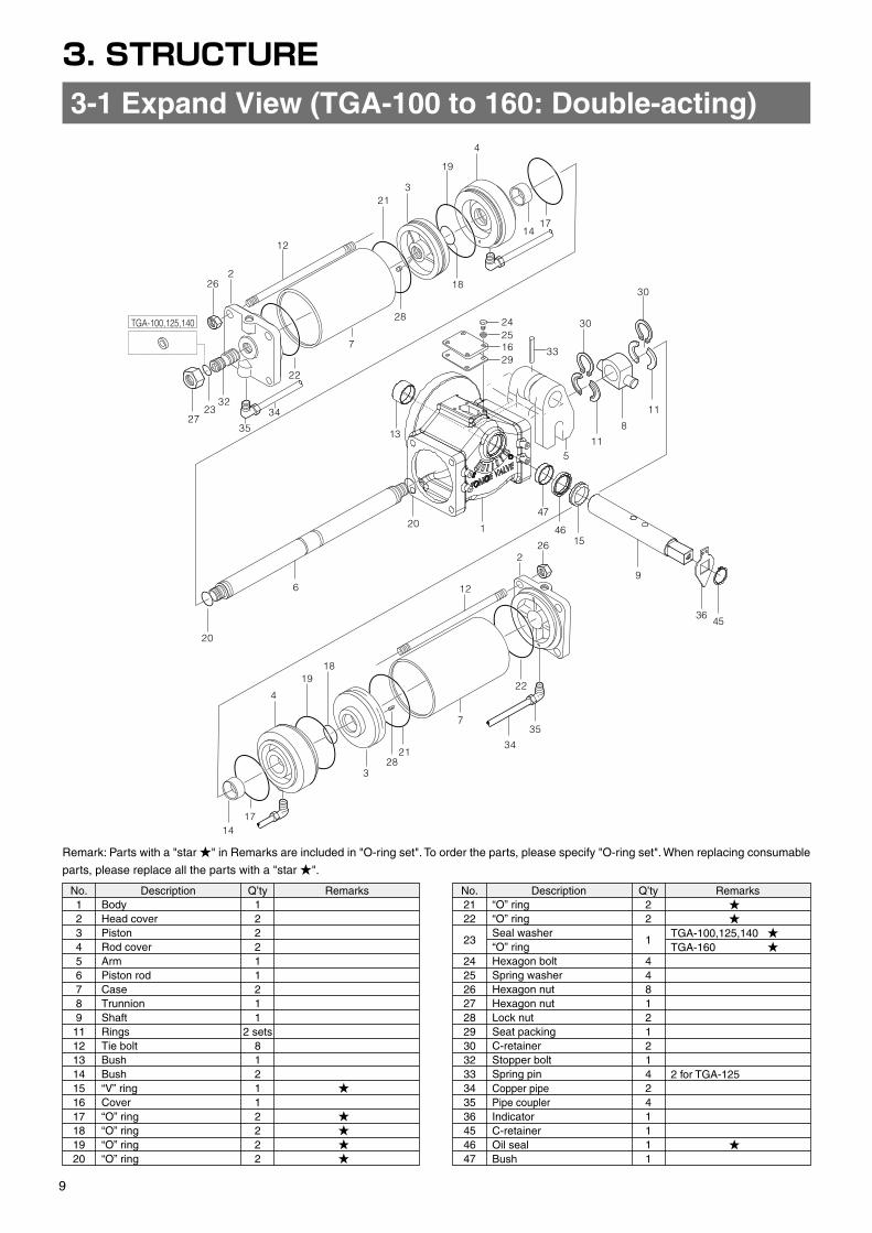
3. STRUCTURE
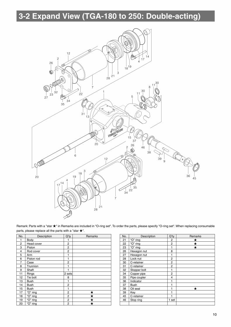
No. Description Q’ty Remarks No. Description Q’ty Remarks No. Description Q’ty Remarks No. Description Q’ty Remarks12345678911121314151617181920
2122
23
242526272829303233343536454647
122211211
2 sets812112222
22
1
448121214241111
BodyHead coverPistonRod coverArmPiston rodCaseTrunnionShaftRingsTie boltBushBush“V” ringCover“O” ring“O” ring“O” ring“O” ring
“O” ring“O” ringSeal washer“O” ringHexagon boltSpring washerHexagon nut Hexagon nut Lock nutSeat packingC-retainer Stopper boltSpring pinCopper pipePipe couplerIndicatorC-retainerOil sealBush
BodyHead coverPistonRod coverArmPiston rodCaseTrunnionShaftRingsTie boltBushBushBush“O” ring“O” ring“O” ring“O” ring
“O” ring“O” ring“O” ringHexagon nut Hexagon nut Lock nutC-retainer C-retainer Stopper boltCopper pipePipe couplerIndicatorBushOil sealKeyC-retainer Stop ring
★
★ ★ ★ ★
★ ★TGA-100,125,140 ★TGA-160 ★
2 for TGA-125
★
123456789
111213141517181920
2122232627283031323435363738394546
122211211
2 sets81212222
2218122212411111
1 set
★ ★ ★ ★
★ ★ ★
★
Remark: Parts with a "star ★" in Remarks are included in "O-ring set". To order the parts, please specify "O-ring set". When replacing consumable
parts, please replace all the parts with a "star ★".
Remark: Parts with a "star ★" in Remarks are included in "O-ring set". To order the parts, please specify "O-ring set". When replacing consumable
parts, please replace all the parts with a "star ★".
3-1 Expand View (TGA-100 to 160: Double-acting)3-2 Expand View (TGA-180 to 250: Double-acting)
9 10
33
1
26
12
1819
4
328
21
1714
22
34
357
5
24251629
30
11
8
11
30
20
20
6
2
4
1714
18
28
7
22
12
226
2723
32
19
321
35
34
TGA-100,125,140
4536
9
1546
47
13
45
1417
4
1918
321
28
1
3113
20
6
2037
15
46
38
226
399
36
3522
34
7
2128
1714
12
1918
3
4
511
308
1130
7
22
3435
3223
27
262
12
3. STRUCTURE
No. Description Q’ty Remarks No. Description Q’ty Remarks No. Description Q’ty Remarks No. Description Q’ty Remarks123456789
11121314151617181920
2122
23
242526272829303233343536454647
122211211
2 sets812112222
22
1
448121214241111
BodyHead coverPistonRod coverArmPiston rodCaseTrunnionShaftRingsTie boltBushBush“V” ringCover“O” ring“O” ring“O” ring“O” ring
“O” ring“O” ringSeal washer“O” ringHexagon boltSpring washerHexagon nut Hexagon nut Lock nutSeat packingC-retainer Stopper boltSpring pinCopper pipePipe couplerIndicatorC-retainerOil sealBush
BodyHead coverPistonRod coverArmPiston rodCaseTrunnionShaftRingsTie boltBushBushBush“O” ring“O” ring“O” ring“O” ring
“O” ring“O” ring“O” ringHexagon nut Hexagon nut Lock nutC-retainer C-retainer Stopper boltCopper pipePipe couplerIndicatorBushOil sealKeyC-retainer Stop ring
★
★ ★ ★ ★
★ ★TGA-100,125,140 ★TGA-160 ★
2 for TGA-125
★
123456789111213141517181920
2122232627283031323435363738394546
122211211
2 sets81212222
2218122212411111
1 set
★ ★ ★ ★
★ ★ ★
★
Remark: Parts with a "star ★" in Remarks are included in "O-ring set". To order the parts, please specify "O-ring set". When replacing consumable
parts, please replace all the parts with a "star ★".
Remark: Parts with a "star ★" in Remarks are included in "O-ring set". To order the parts, please specify "O-ring set". When replacing consumable
parts, please replace all the parts with a "star ★".
3-1 Expand View (TGA-100 to 160: Double-acting)3-2 Expand View (TGA-180 to 250: Double-acting)
9 10
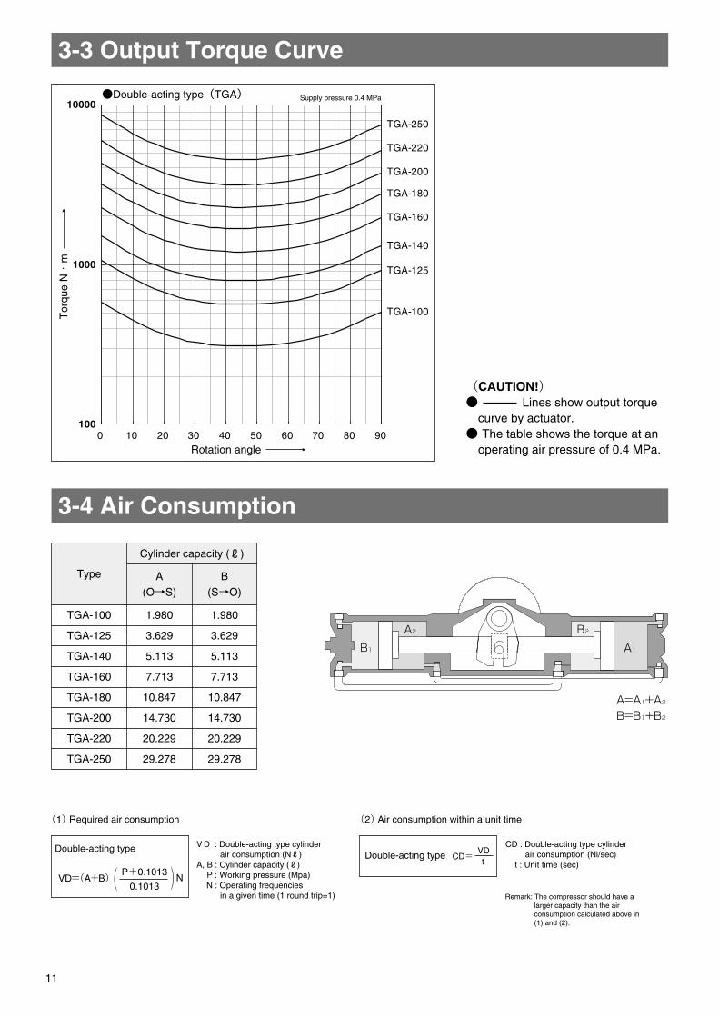
100
1000
10000
0 10 20 30 40 50 60 70 80 90
TGA-100
TGA-125
TGA-140
TGA-160
TGA-180
TGA-200
TGA-220
TGA-250
A1
A2B1
B2
P2(APPROX.)P1(APPROX.)
A(APPROX.)
n-M tap, depth N
VIEW"E"
φC1
φF
E
φd
f1(APPROX.)
Air connection port 2-G
f2(APPROX.)
B
HH
1
a1a2
b
●Double-acting type(TGA) Supply pressure 0.4 MPa
Tor
que
N・
m
Rotation angle
TGA-100
TGA-125
TGA-140
TGA-160
TGA-180
TGA-200
TGA-220
TGA-250
A
(O→S)
1.980
3.629
5.113
7.713
10.847
14.730
20.229
29.278
B
(S→O)
1.980
3.629
5.113
7.713
10.847
14.730
20.229
29.278
A=A1+A2B=B1+B2 TGA-100
TGA-125
TGA-140
TGA-160
TGA-180
TGA-200
TGA-220
TGA-250
682
754
840
954
1069
1175
1263
1393
350
381
432
483
543
599
642
707
332
373
408
471
526
576
621
687
50
62
70
80
90
100
110
125
133
164
180
203
221
254
271
302
189
234
282
310
323
370
400
433
45
45
60
61
65
70
85
100
30
30
45
60
65
75
75
75
10
12
12
15
18
20
20
20
2
2
2
2
2
2
2
2
40
40
55
55
60
65
80
95
155
200
200
260
260
320
320
320
125
170
170
220
220
280
280
280
4
4
4
4
4
8
8
8
M12
M16
M16
M20
M20
M20
M20
M20
15
20
20
25
25
25
25
25
Rc1/4
Rc3/8
Rc3/8
Rc3/8
Rc3/8
Rc1/2
Rc1/2
Rc1/2
77.5
100
100
130
130
160
160
160
18
31
40
84
115
163
188
254
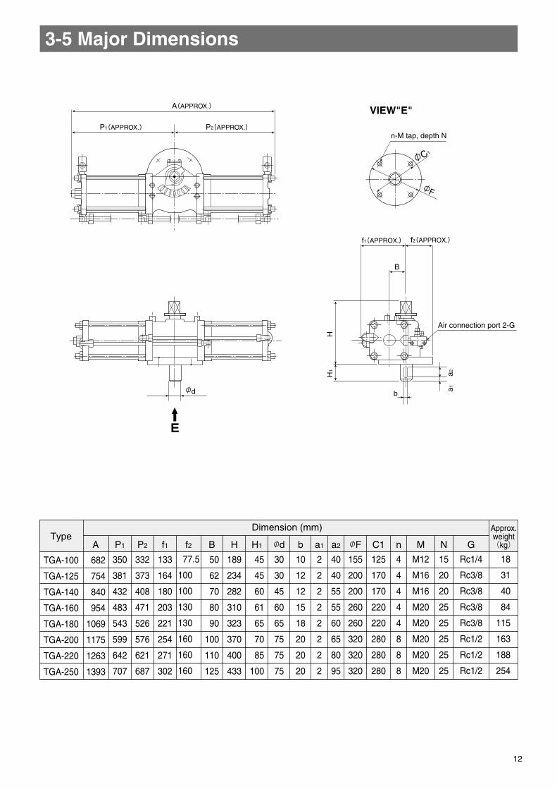
A P1 P2 Bf2f1 H H1 φd b a1 a2 φF C1 n M N G
3-5 Major Dimensions3-3 Output Torque Curve
3-4 Air Consumption
Type
Cylinder capacity (ℓ)
V D : Double-acting type cylinder air consumption (Nℓ)A, B : Cylinder capacity (ℓ) P : Working pressure (Mpa) N : Operating frequencies in a given time (1 round trip=1)
(1) Required air consumption (2) Air consumption within a unit time
Double-acting typeDouble-acting type
VD=(A+B) P+0.1013
0.1013N
CD= VDt
CD : Double-acting type cylinder air consumption (Nl/sec) t : Unit time (sec)
Remark: The compressor should have a larger capacity than the air consumption calculated above in (1) and (2).
(CAUTION!)● Lines show output torque
curve by actuator.● The table shows the torque at an
operating air pressure of 0.4 MPa.
TypeDimension (mm) Approx.
weight(kg)
11 12
100
1000
10000
0 10 20 30 40 50 60 70 80 90
TGA-100
TGA-125
TGA-140
TGA-160
TGA-180
TGA-200
TGA-220
TGA-250
A1
A2B1
B2
P2(APPROX.)P1(APPROX.)
A(APPROX.)
n-M tap, depth N
VIEW"E"
φC1
φF
E
φd
f1(APPROX.)
Air connection port 2-G
f2(APPROX.)
B
HH
1
a1a2
b
●Double-acting type(TGA) Supply pressure 0.4 MPa
Tor
que
N・
m
Rotation angle
TGA-100
TGA-125
TGA-140
TGA-160
TGA-180
TGA-200
TGA-220
TGA-250
A
(O→S)
1.980
3.629
5.113
7.713
10.847
14.730
20.229
29.278
B
(S→O)
1.980
3.629
5.113
7.713
10.847
14.730
20.229
29.278
A=A1+A2B=B1+B2 TGA-100
TGA-125
TGA-140
TGA-160
TGA-180
TGA-200
TGA-220
TGA-250
682
754
840
954
1069
1175
1263
1393
350
381
432
483
543
599
642
707
332
373
408
471
526
576
621
687
50
62
70
80
90
100
110
125
133
164
180
203
221
254
271
302
189
234
282
310
323
370
400
433
45
45
60
61
65
70
85
100
30
30
45
60
65
75
75
75
10
12
12
15
18
20
20
20
2
2
2
2
2
2
2
2
40
40
55
55
60
65
80
95
155
200
200
260
260
320
320
320
125
170
170
220
220
280
280
280
4
4
4
4
4
8
8
8
M12
M16
M16
M20
M20
M20
M20
M20
15
20
20
25
25
25
25
25
Rc1/4
Rc3/8
Rc3/8
Rc3/8
Rc3/8
Rc1/2
Rc1/2
Rc1/2
77.5
100
100
130
130
160
160
160
18
31
40
84
115
163
188
254
A P1 P2 Bf2f1 H H1 φd b a1 a2 φF C1 n M N G
3-5 Major Dimensions3-3 Output Torque Curve
3-4 Air Consumption
Type
Cylinder capacity (ℓ)
V D : Double-acting type cylinder air consumption (Nℓ)A, B : Cylinder capacity (ℓ) P : Working pressure (Mpa) N : Operating frequencies in a given time (1 round trip=1)
(1) Required air consumption (2) Air consumption within a unit time
Double-acting typeDouble-acting type
VD=(A+B) P+0.1013
0.1013N
CD= VDt
CD : Double-acting type cylinder air consumption (Nl/sec) t : Unit time (sec)
Remark: The compressor should have a larger capacity than the air consumption calculated above in (1) and (2).
(CAUTION!)● Lines show output torque
curve by actuator.● The table shows the torque at an
operating air pressure of 0.4 MPa.
TypeDimension (mm) Approx.
weight(kg)
11 12
4. CYLINDER SYSTEM CONFIGURATION
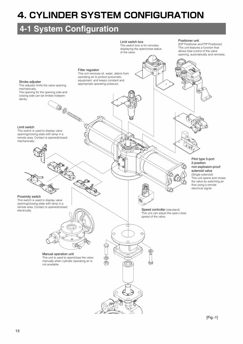
Limit switch boxThis switch box is for remotely displaying the open/close status of the valve.
Filter regulatorThis unit removes oil, water, debris from operating air to protect pneumatic equipment, and keeps constant and appropriate operating pressure.
Limit switchThis switch is used to display valve opening/closing state with lamp in a remote area. Contact is opened/closed mechanically.
Proximity switchThis switch is used to display valve opening/closing state with lamp in a remote area. Contact is opened/closed electrically.
Manual operation unitThis unit is used to open/close the valve manually when cylinder operating air is not available.
Speed controller (standard)This unit can adjust the open-close speed of the valve.
Pilot type 5-port 2-position non-explosion-proof solenoid valve (Single solenoid)This unit opens and closes the valve by switching air flow using a remote electrical signal.
Stroke adjusterThis adjuster limits the valve opening mechanically.The opening for the opening side and closing side can be limited indepen-dently.
Positioner unit(E/P Positioner and P/P Positioner)This unit features a function that allows total control of the valve opening, automatically and remotely.
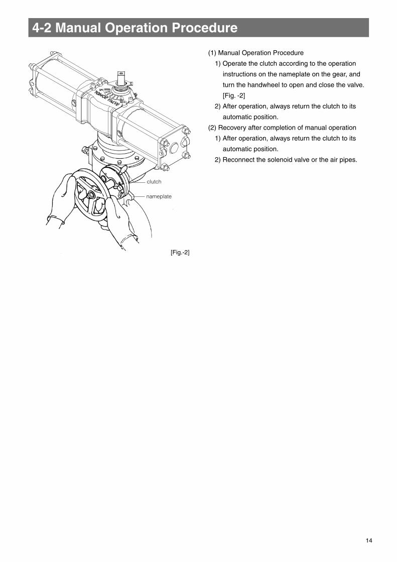
clutch
nameplate
(1) Manual Operation Procedure
1) Operate the clutch according to the operation
instructions on the nameplate on the gear, and
turn the handwheel to open and close the valve.
[Fig. -2]
2) After operation, always return the clutch to its
automatic position.
(2) Recovery after completion of manual operation
1) After operation, always return the clutch to its
automatic position.
2) Reconnect the solenoid valve or the air pipes.
4-2 Manual Operation Procedure4-1 System Configuration
[Fig.-2]
[Fig.-1]
13 14
4. CYLINDER SYSTEM CONFIGURATION
Limit switch boxThis switch box is for remotely displaying the open/close status of the valve.
Filter regulatorThis unit removes oil, water, debris from operating air to protect pneumatic equipment, and keeps constant and appropriate operating pressure.
Limit switchThis switch is used to display valve opening/closing state with lamp in a remote area. Contact is opened/closed mechanically.
Proximity switchThis switch is used to display valve opening/closing state with lamp in a remote area. Contact is opened/closed electrically.
Manual operation unitThis unit is used to open/close the valve manually when cylinder operating air is not available.
Speed controller (standard)This unit can adjust the open-close speed of the valve.
Pilot type 5-port 2-position non-explosion-proof solenoid valve (Single solenoid)This unit opens and closes the valve by switching air flow using a remote electrical signal.
Stroke adjusterThis adjuster limits the valve opening mechanically.The opening for the opening side and closing side can be limited indepen-dently.
Positioner unit(E/P Positioner and P/P Positioner)This unit features a function that allows total control of the valve opening, automatically and remotely.
clutch
nameplate
(1) Manual Operation Procedure
1) Operate the clutch according to the operation
instructions on the nameplate on the gear, and
turn the handwheel to open and close the valve.
[Fig. -2]
2) After operation, always return the clutch to its
automatic position.
(2) Recovery after completion of manual operation
1) After operation, always return the clutch to its
automatic position.
2) Reconnect the solenoid valve or the air pipes.
4-2 Manual Operation Procedure4-1 System Configuration
[Fig.-2]
[Fig.-1]
13 14
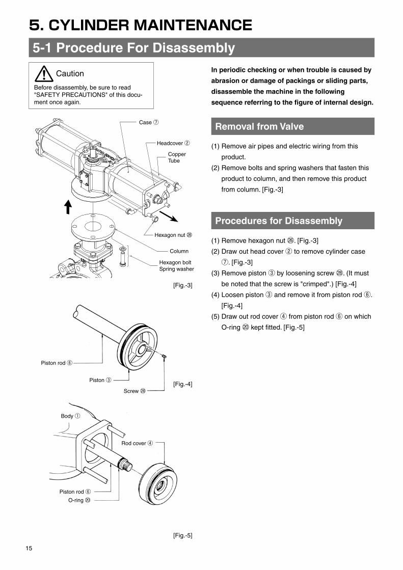
5. CYLINDER MAINTENANCE
Removal from Valve
Procedures for Disassembly
Case ⑦
Case ⑦Copper Tube
Headcover ②
Column
C-retainer 45
Indicator 36
V-ring ⑮
Oil seal 46Arm ⑤Spring pin 33Seat packing ㉙
Cover ⑯Spring Washer ㉕Hexagon Bolt ㉔
Bush 47
stopper bolt 32
hexagon nut ㉗
Shaft ⑨
Trunnion ⑧
Bush ⑬
O-ring ⑳
Screw ㉘
Hexagon nut ㉖
(1) Remove air pipes and electric wiring from this
product.
(2) Remove bolts and spring washers that fasten this
product to column, and then remove this product
from column. [Fig.-3]
(1) Remove hexagon nut ㉖. [Fig.-3]
(2) Draw out head cover ② to remove cylinder case
⑦. [Fig.-3]
(3) Remove piston ③ by loosening screw ㉘. (It must
be noted that the screw is "crimped".) [Fig.-4]
(4) Loosen piston ③ and remove it from piston rod ⑥.
[Fig.-4]
(5) Draw out rod cover ④ from piston rod ⑥ on which
O-ring ⑳ kept fitted. [Fig.-5]
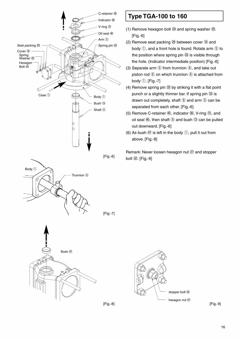
(1) Remove hexagon bolt ㉔ and spring washer ㉕. [Fig.-6]
(2) Remove seat packing ㉙ between cover ⑯ and
body ①, and a front hole is found. Rotate arm ⑤ to
the position where spring pin 33 is visible through
the hole. (Indicator intermediate position) [Fig.-6]
(3) Separate arm ⑤ from trunnion ⑧, and take out
piston rod ⑥ on which trunnion ⑧ is attached from
body ①. [Fig.-7]
(4) Remove spring pin 33 by striking it with a flat point
punch or a slightly thinner bar. If spring pin 33 is
drawn out completely, shaft ⑨ and arm ⑤ can be
separated from each other. [Fig.-6]
(5) Remove C-retainer 45, indicator 36, V-ring ⑮, and
oil seal 46, then shaft ⑨ and bush ⑬ can be pulled
out downward. [Fig.-6]
(6) As bush 47 is left in the body ①, pull it out from
above. [Fig.-8]
Remark: Never loosen hexagon nut ㉗ and stopper
bolt 32. [Fig.-9]
Caution
Before disassembly, be sure to read "SAFETY PRECAUTIONS" of this docu-ment once again.
5-1 Procedure For Disassembly
Type TGA-100 to 160
Piston rod ⑥
Piston rod ⑥
Piston ③
Body ①
Body ①
Body ①
Rod cover ④
Hexagon boltSpring washer
[Fig.-4]
[Fig.-3]
[Fig.-5]
[Fig.-8] [Fig.-9]
[Fig.-7]
[Fig.-6]
In periodic checking or when trouble is caused by
abrasion or damage of packings or sliding parts,
disassemble the machine in the following
sequence referring to the figure of internal design.
15 16
5. CYLINDER MAINTENANCE
Removal from Valve
Procedures for Disassembly
Case ⑦
Case ⑦Copper Tube
Headcover ②
Column
C-retainer 45
Indicator 36
V-ring ⑮
Oil seal 46Arm ⑤Spring pin 33Seat packing ㉙
Cover ⑯Spring Washer ㉕Hexagon Bolt ㉔
Bush 47
stopper bolt 32
hexagon nut ㉗
Shaft ⑨
Trunnion ⑧
Bush ⑬
O-ring ⑳
Screw ㉘
Hexagon nut ㉖
(1) Remove air pipes and electric wiring from this
product.
(2) Remove bolts and spring washers that fasten this
product to column, and then remove this product
from column. [Fig.-3]
(1) Remove hexagon nut ㉖. [Fig.-3]
(2) Draw out head cover ② to remove cylinder case
⑦. [Fig.-3]
(3) Remove piston ③ by loosening screw ㉘. (It must
be noted that the screw is "crimped".) [Fig.-4]
(4) Loosen piston ③ and remove it from piston rod ⑥.
[Fig.-4]
(5) Draw out rod cover ④ from piston rod ⑥ on which
O-ring ⑳ kept fitted. [Fig.-5]
(1) Remove hexagon bolt ㉔ and spring washer ㉕. [Fig.-6]
(2) Remove seat packing ㉙ between cover ⑯ and
body ①, and a front hole is found. Rotate arm ⑤ to
the position where spring pin 33 is visible through
the hole. (Indicator intermediate position) [Fig.-6]
(3) Separate arm ⑤ from trunnion ⑧, and take out
piston rod ⑥ on which trunnion ⑧ is attached from
body ①. [Fig.-7]
(4) Remove spring pin 33 by striking it with a flat point
punch or a slightly thinner bar. If spring pin 33 is
drawn out completely, shaft ⑨ and arm ⑤ can be
separated from each other. [Fig.-6]
(5) Remove C-retainer 45, indicator 36, V-ring ⑮, and
oil seal 46, then shaft ⑨ and bush ⑬ can be pulled
out downward. [Fig.-6]
(6) As bush 47 is left in the body ①, pull it out from
above. [Fig.-8]
Remark: Never loosen hexagon nut ㉗ and stopper
bolt 32. [Fig.-9]
Caution
Before disassembly, be sure to read "SAFETY PRECAUTIONS" of this docu-ment once again.
5-1 Procedure For Disassembly
Type TGA-100 to 160
Piston rod ⑥
Piston rod ⑥
Piston ③
Body ①
Body ①
Body ①
Rod cover ④
Hexagon boltSpring washer
[Fig.-4]
[Fig.-3]
[Fig.-5]
[Fig.-8] [Fig.-9]
[Fig.-7]
[Fig.-6]
In periodic checking or when trouble is caused by
abrasion or damage of packings or sliding parts,
disassemble the machine in the following
sequence referring to the figure of internal design.
15 16
Stop ring 46
Shaft ⑨
Key 39
Bush ⑮Arm ⑤
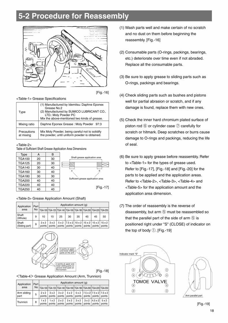
<Table-1> Grease Specifications
<Table-3> Grease Application Amount (Shaft)
<Table-4> Grease Application Amount (Arm, Trunnion)
<Table-2>Table of Sufficient Shaft Grease Application Area Dimensions
A B
TypeTGA100TGA125TGA140TGA160TGA180TGA200TGA220TGA250
A2020303030404040
B3030404030404040
Daphne Eponex Grease : Moly Powder 97:3
Mix Moly Powder, being careful not to solidify the powder, until uniform powder is obtained.
(1) Manufactured by Idemitsu: Daphne Eponex Grease No.2
(2) Manufactured by SUMICO LUBRICANT CO., LTD.: Moly Powder PC
Mix the above-mentioned two kinds of grease.
Application area
Shaft (Whole)
Shaft (Sliding part)
Application amount (g)PartNo
9 10 15 25 30 35 45 45 50
9
5
8
15 x 2points
15 x 2points
15 x 2points
10 x 2points
7.5 x 2points
5 x 2points
3 x 2points
3 x 2points
TGA-100 TGA-125 TGA-140 TGA-160 TGA-180 TGA-200 TGA-220 TGA-250
5 x 2points
4.5 x 2points
3 x 2points
3 x 2points
3 x 2points
2 x 2points
1 x 2points
1 x 2points
7.5 x 2points
7.5 x 2points
7.5 x 2points
5 x 2points
5 x 2points
3 x 2points
3 x 2points
2 x 2points
TGA-100 TGA-125 TGA-140 TGA-160 TGA-180 TGA-200 TGA-220 TGA-250Application
area
Arm sliding part
Trunnion
Application amount (g)Part No
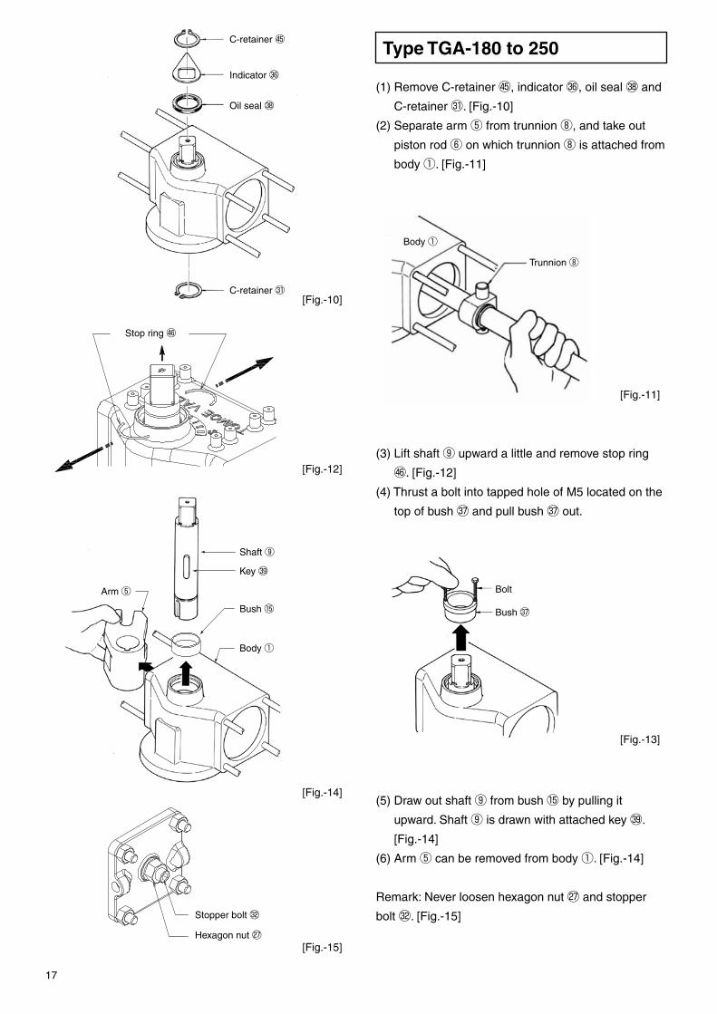
(1) Remove C-retainer 45, indicator 36, oil seal 38 and
C-retainer ㉛. [Fig.-10]
(2) Separate arm ⑤ from trunnion ⑧, and take out
piston rod ⑥ on which trunnion ⑧ is attached from
body ①. [Fig.-11]
(3) Lift shaft ⑨ upward a little and remove stop ring
46.[Fig.-12]
(4) Thrust a bolt into tapped hole of M5 located on the
top of bush 37 and pull bush 37 out.
(5) Draw out shaft ⑨ from bush ⑮ by pulling it
upward. Shaft ⑨ is drawn with attached key 39.
[Fig.-14]
(6) Arm ⑤ can be removed from body ①. [Fig.-14]
Remark: Never loosen hexagon nut ㉗ and stopper
bolt 32. [Fig.-15]
(1) Wash parts well and make certain of no scratch
and no dust on them before beginning the
reassembly. [Fig.-16]
(2) Consumable parts (O-rings, packings, bearings,
etc.) deteriorate over time even if not abraded.
Replace all the consumable parts.
(3) Be sure to apply grease to sliding parts such as
O-rings, packings and bearings.
(4) Check sliding parts such as bushes and pistons
well for partial abrasion or scratch, and if any
damage is found, replace them with new ones.
(5) Check the inner hard chromium plated surface of
piston rod ⑥ or cylinder case ⑦ carefully for
scratch or hitmark. Deep scratches or burrs cause
damage to O-rings and packings, reducing the life
of seal.
(6) Be sure to apply grease before reassembly. Refer
to <Table-1> for the types of grease used.
Refer to [Fig.-17], [Fig.-18] and [Fig.-20] for the
parts to be applied and the application areas.
Refer to <Table-2>, <Table-3>, <Table-4> and
<Table-5> for the application amount and the
application area dimension.
(7) The order of reassembly is the reverse of
disassembly, but arm ⑤ must be reassembled so
that the parallel part of the side of arm ⑤ is
positioned right under "S" (CLOSE) of indicator on
the top of body ①. [Fig.-19]
Type TGA-180 to 250C-retainer 45
C-retainer ㉛
Indicator 36
Oil seal 38
Trunnion ⑧
Body ①
Stopper bolt 32
Hexagon nut ㉗
Body ①
[Fig.-17]
[Fig.-16]
[Fig.-18]
[Fig.-19]
[Fig.-13]
[Fig.-11]
[Fig.-10]
[Fig.-12]
[Fig.-14]
[Fig.-15]
Type
Precautions at mixing
Mixing ratio
Shaft grease application area
Sufficient grease application area
2 points at upper and lower sliding parts on the arm
2 points at upper and lower sliding parts (U groove inner part) on the trunnion
Indicator mark "S"
Arm parallel part
5-2 Procedure for Reassembly
Bush 37
Bolt
17 18
Stop ring 46
Shaft ⑨
Key 39
Bush ⑮Arm ⑤
<Table-1> Grease Specifications
<Table-3> Grease Application Amount (Shaft)
<Table-4> Grease Application Amount (Arm, Trunnion)
<Table-2>Table of Sufficient Shaft Grease Application Area Dimensions
A B
TypeTGA100TGA125TGA140TGA160TGA180TGA200TGA220TGA250
A2020303030404040
B3030404030404040
Daphne Eponex Grease : Moly Powder 97:3
Mix Moly Powder, being careful not to solidify the powder, until uniform powder is obtained.
(1) Manufactured by Idemitsu: Daphne Eponex Grease No.2
(2) Manufactured by SUMICO LUBRICANT CO., LTD.: Moly Powder PC
Mix the above-mentioned two kinds of grease.
Application area
Shaft (Whole)
Shaft (Sliding part)
Application amount (g)PartNo
9 10 15 25 30 35 45 45 50
9
5
8
15 x 2points
15 x 2points
15 x 2points
10 x 2points
7.5 x 2points
5 x 2points
3 x 2points
3 x 2points
TGA-100 TGA-125 TGA-140 TGA-160 TGA-180 TGA-200 TGA-220 TGA-250
5 x 2points
4.5 x 2points
3 x 2points
3 x 2points
3 x 2points
2 x 2points
1 x 2points
1 x 2points
7.5 x 2points
7.5 x 2points
7.5 x 2points
5 x 2points
5 x 2points
3 x 2points
3 x 2points
2 x 2points
TGA-100 TGA-125 TGA-140 TGA-160 TGA-180 TGA-200 TGA-220 TGA-250Application
area
Arm sliding part
Trunnion
Application amount (g)Part No
(1) Remove C-retainer 45, indicator 36, oil seal 38 and
C-retainer ㉛. [Fig.-10]
(2) Separate arm ⑤ from trunnion ⑧, and take out
piston rod ⑥ on which trunnion ⑧ is attached from
body ①. [Fig.-11]
(3) Lift shaft ⑨ upward a little and remove stop ring
46.[Fig.-12]
(4) Thrust a bolt into tapped hole of M5 located on the
top of bush 37 and pull bush 37 out.
(5) Draw out shaft ⑨ from bush ⑮ by pulling it
upward. Shaft ⑨ is drawn with attached key 39.
[Fig.-14]
(6) Arm ⑤ can be removed from body ①. [Fig.-14]
Remark: Never loosen hexagon nut ㉗ and stopper
bolt 32. [Fig.-15]
(1) Wash parts well and make certain of no scratch
and no dust on them before beginning the
reassembly. [Fig.-16]
(2) Consumable parts (O-rings, packings, bearings,
etc.) deteriorate over time even if not abraded.
Replace all the consumable parts.
(3) Be sure to apply grease to sliding parts such as
O-rings, packings and bearings.
(4) Check sliding parts such as bushes and pistons
well for partial abrasion or scratch, and if any
damage is found, replace them with new ones.
(5) Check the inner hard chromium plated surface of
piston rod ⑥ or cylinder case ⑦ carefully for
scratch or hitmark. Deep scratches or burrs cause
damage to O-rings and packings, reducing the life
of seal.
(6) Be sure to apply grease before reassembly. Refer
to <Table-1> for the types of grease used.
Refer to [Fig.-17], [Fig.-18] and [Fig.-20] for the
parts to be applied and the application areas.
Refer to <Table-2>, <Table-3>, <Table-4> and
<Table-5> for the application amount and the
application area dimension.
(7) The order of reassembly is the reverse of
disassembly, but arm ⑤ must be reassembled so
that the parallel part of the side of arm ⑤ is
positioned right under "S" (CLOSE) of indicator on
the top of body ①. [Fig.-19]
Type TGA-180 to 250C-retainer 45
C-retainer ㉛
Indicator 36
Oil seal 38
Trunnion ⑧
Body ①
Stopper bolt 32
Hexagon nut ㉗
Body ①
[Fig.-17]
[Fig.-16]
[Fig.-18]
[Fig.-19]
[Fig.-13]
[Fig.-11]
[Fig.-10]
[Fig.-12]
[Fig.-14]
[Fig.-15]
Type
Precautions at mixing
Mixing ratio
Shaft grease application area
Sufficient grease application area
2 points at upper and lower sliding parts on the arm
2 points at upper and lower sliding parts (U groove inner part) on the trunnion
Indicator mark "S"
Arm parallel part
5-2 Procedure for Reassembly
Bush 37
Bolt
17 18
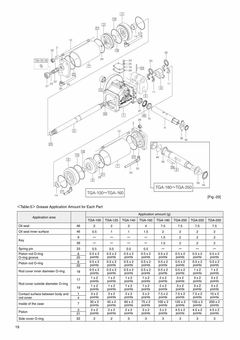
33
1
26
12
1819
4
328
21
1714
22
34
357
5
24251629
30
11
8
11
30
20
20
6
2
4
1714
18
28
7
22
12
226
2723
32
19
321
35
34
TGA-125,140
4536
9
1546
47
13
45
46
38
399
36
Tie bolt ⑫
Head cover ②
Stopper bolt 32
2 2 3 3 3 3 3 3
TGA-100
2
0.5
ーー0.5
2
1
ーー0.5
3
1
ーー0.5
4
1.5
ーー0.5
7.5
2
1.5
1.5
ー
7.5
2
2
2
ー
7.5
2
2
2
ー
7.5
2
2
2
ー
TGA-125 TGA-140 TGA-160 TGA-180 TGA-200 TGA-220 TGA-250
②
32
⑫
±10%
±10%
±10%
M6x155.07Nm
M20206Nm
M1467.6Nm
M6x155.07Nm
M20206Nm
M1467.6Nm
M6x155.07Nm
M24356Nm
M16106Nm
M6x155.07Nm
M30707Nm
M16106Nm
M6x155.07Nm
M33962Nm
M18145Nm
M6x155.07Nm
M33962Nm
M20206Nm
M6x155.07Nm
M33962Nm
M20206Nm
M6x155.07Nm
M33962Nm
M22280Nm
TGA-100Area
Trouble Cause of Trouble Remedy
Tightening toolTightening torquetolerancePart No TGA-125 TGA-140 TGA-160 TGA-180 TGA-200 TGA-220 TGA-250
Oil seal
Oil seal inner surface
Key
Spring pin
Piston rod O-ringO-ring groove
Piston rod O-ring
Rod cover inner diameter O-ring
Rod cover outside diameter O-ring
Contact surface between body and rod cover
Inside of the case
Piston
Side cover O-ring
Cover mounting bolt
Stopper bolt
Tie bolt
Impact tool
Tightening tool
Impact tool
46
46
9
39
33
620620
18
17
19
14
7
321
22
TGA-100~TGA-160TGA-180~TGA-250
Application areaApplication amount (g)
(8) Tighten head cover ②, tie bolt ⑫ and stopper bolt
32 securely according to torque values in
<Table-6>. [Fig.-21]
[Fig.-21]
[Fig.-20]
<Table-5> Grease Application Amount for Each Part
<Table-6> Bolt Tightening Torque
5-3 Troubleshooting
The cylinder unit does not open/close valve.
The valve is not fully opened or shut.
The valve opens/closes too quickly.
The valve opens/closes too slowly.
Air leaks.
- Supply pressure of compressed air, etc. is low.
- Air pipes clogged.
- Speed controller is shut or throttled.
- Air leaks inside the cylinder case.
- Torque required by a valve is too high.
- Wrong positioning of the stoppers.
- Torque required by a valve is too high. - Check the valve.
- Speed controller is opened too much.
- Supply pressure of compressed air, etc. is high.
- Speed controller is closed too much.
- Supply pressure of compressed air, etc. is low.
- Air pipe from compressor to this product is too long.
- Cover packing of output shaft or case cover is worn out.
- Loosened bolts of side cover
- Increase the air supply pressure within the range of the specifications of this product.
- Remove foreign substances from the air pipes.
- Open the speed controller.
- Check O-rings of the piston.
- Check the valve.
- Adjust the stopper positioning.
- Check the valve.
- Close the knob of the speed controller.
- Decrease the air supply pressure within the range of the specifications of this product.
- Open the knob of the speed controller.
- Increase the air supply pressure within the range of the specifications of this product.
- Increase the diameter of the air pipe.
- Replace the consumable parts.
- Retighten the bolts.0.5 x 2points
0.5 x 2points
0.5 x 2points
0.5 x 2points
0.5 x 2points
0.5 x 2points
0.5 x 2points
0.5 x 2points
0.5 x 2points
0.5 x 2points
0.5 x 2points
0.5 x 2points
0.5 x 2points
0.5 x 2points
0.5 x 2points
0.5 x 2points
0.5 x 2points
0.5 x 2points
0.5 x 2points
0.5 x 2points
0.5 x 2points
0.5 x 2points
1 x 2points
1 x 2points
1 x 2points
1 x 2points
1 x 2points
1 x 2points
2 x 2points
3 x 2points
3 x 2points
3 x 2points
1 x 2points
1 x 2points
1 x 2points
1 x 2points
2 x 2points
3 x 2points
3 x 2points
3 x 2points
3 x 2points
3 x 2points
3 x 2points
3 x 2points
7.5 x 2points
7.5 x 2points
7.5 x 2points
10 x 2points
30 x 2points
45 x 2points
60 x 2points
75 x 2points
100 x 2points
125 x 2points
150 x 2points
200 x 2points
2 x 2points
2 x 2points
2 x 2points
3 x 2points
3 x 2points
4.5 x 2points
4.5 x 2points
4.5 x 2points
19 20
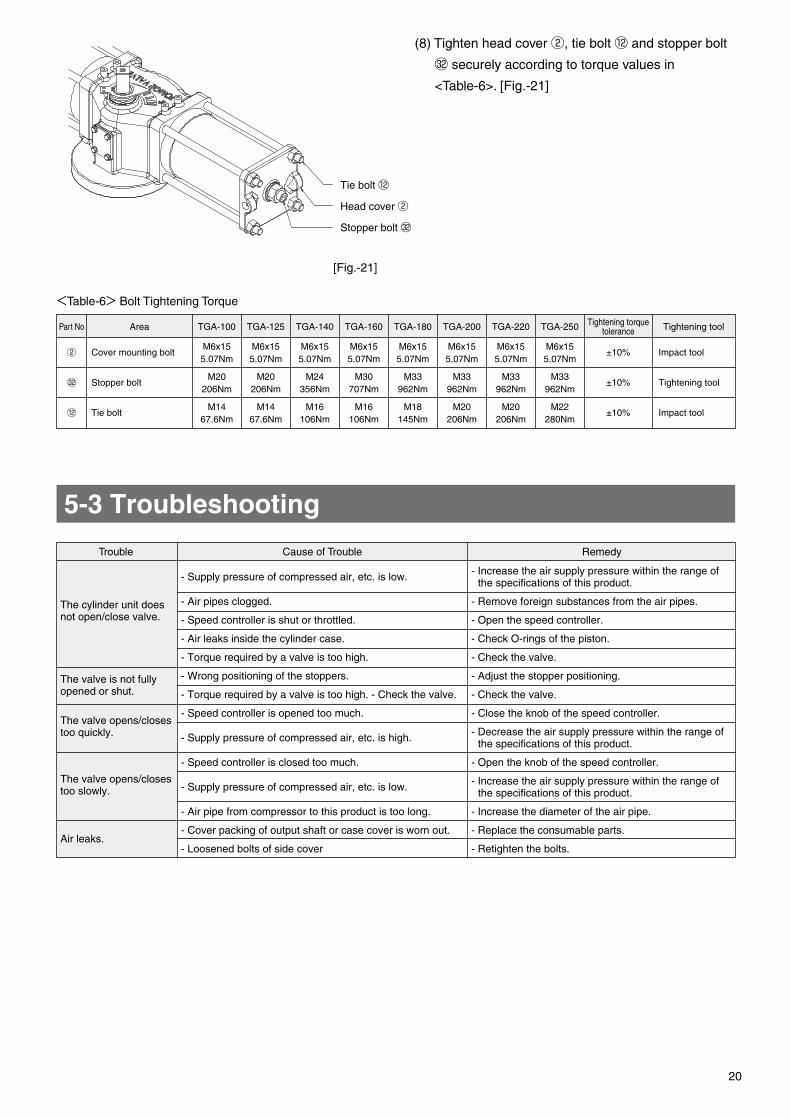
33
1
26
12
1819
4
328
21
1714
22
34
357
5
24251629
30
11
8
11
30
20
20
6
2
4
1714
18
28
7
22
12
226
2723
32
19
321
35
34
TGA-125,140
4536
9
1546
47
13
45
46
38
399
36
Tie bolt ⑫
Head cover ②
Stopper bolt 32
2 2 3 3 3 3 3 3
TGA-100
2
0.5
ーー0.5
2
1
ーー0.5
3
1
ーー0.5
4
1.5
ーー0.5
7.5
2
1.5
1.5
ー
7.5
2
2
2
ー
7.5
2
2
2
ー
7.5
2
2
2
ー
TGA-125 TGA-140 TGA-160 TGA-180 TGA-200 TGA-220 TGA-250
②
32
⑫
±10%
±10%
±10%
M6x155.07Nm
M20206Nm
M1467.6Nm
M6x155.07Nm
M20206Nm
M1467.6Nm
M6x155.07Nm
M24356Nm
M16106Nm
M6x155.07Nm
M30707Nm
M16106Nm
M6x155.07Nm
M33962Nm
M18145Nm
M6x155.07Nm
M33962Nm
M20206Nm
M6x155.07Nm
M33962Nm
M20206Nm
M6x155.07Nm
M33962Nm
M22280Nm
TGA-100Area
Trouble Cause of Trouble Remedy
Tightening toolTightening torquetolerancePart No TGA-125 TGA-140 TGA-160 TGA-180 TGA-200 TGA-220 TGA-250
Oil seal
Oil seal inner surface
Key
Spring pin
Piston rod O-ringO-ring groove
Piston rod O-ring
Rod cover inner diameter O-ring
Rod cover outside diameter O-ring
Contact surface between body and rod cover
Inside of the case
Piston
Side cover O-ring
Cover mounting bolt
Stopper bolt
Tie bolt
Impact tool
Tightening tool
Impact tool
46
46
9
39
33
620620
18
17
19
14
7
321
22
TGA-100~TGA-160TGA-180~TGA-250
Application areaApplication amount (g)
(8) Tighten head cover ②, tie bolt ⑫ and stopper bolt
32 securely according to torque values in
<Table-6>. [Fig.-21]
[Fig.-21]
[Fig.-20]
<Table-5> Grease Application Amount for Each Part
<Table-6> Bolt Tightening Torque
5-3 Troubleshooting
The cylinder unit does not open/close valve.
The valve is not fully opened or shut.
The valve opens/closes too quickly.
The valve opens/closes too slowly.
Air leaks.
- Supply pressure of compressed air, etc. is low.
- Air pipes clogged.
- Speed controller is shut or throttled.
- Air leaks inside the cylinder case.
- Torque required by a valve is too high.
- Wrong positioning of the stoppers.
- Torque required by a valve is too high. - Check the valve.
- Speed controller is opened too much.
- Supply pressure of compressed air, etc. is high.
- Speed controller is closed too much.
- Supply pressure of compressed air, etc. is low.
- Air pipe from compressor to this product is too long.
- Cover packing of output shaft or case cover is worn out.
- Loosened bolts of side cover
- Increase the air supply pressure within the range of the specifications of this product.
- Remove foreign substances from the air pipes.
- Open the speed controller.
- Check O-rings of the piston.
- Check the valve.
- Adjust the stopper positioning.
- Check the valve.
- Close the knob of the speed controller.
- Decrease the air supply pressure within the range of the specifications of this product.
- Open the knob of the speed controller.
- Increase the air supply pressure within the range of the specifications of this product.
- Increase the diameter of the air pipe.
- Replace the consumable parts.
- Retighten the bolts.0.5 x 2points
0.5 x 2points
0.5 x 2points
0.5 x 2points
0.5 x 2points
0.5 x 2points
0.5 x 2points
0.5 x 2points
0.5 x 2points
0.5 x 2points
0.5 x 2points
0.5 x 2points
0.5 x 2points
0.5 x 2points
0.5 x 2points
0.5 x 2points
0.5 x 2points
0.5 x 2points
0.5 x 2points
0.5 x 2points
0.5 x 2points
0.5 x 2points
1 x 2points
1 x 2points
1 x 2points
1 x 2points
1 x 2points
1 x 2points
2 x 2points
3 x 2points
3 x 2points
3 x 2points
1 x 2points
1 x 2points
1 x 2points
1 x 2points
2 x 2points
3 x 2points
3 x 2points
3 x 2points
3 x 2points
3 x 2points
3 x 2points
3 x 2points
7.5 x 2points
7.5 x 2points
7.5 x 2points
10 x 2points
30 x 2points
45 x 2points
60 x 2points
75 x 2points
100 x 2points
125 x 2points
150 x 2points
200 x 2points
2 x 2points
2 x 2points
2 x 2points
3 x 2points
3 x 2points
4.5 x 2points
4.5 x 2points
4.5 x 2points
19 20

122223334679910111112131314151516171820
Fig.No.3ATGAPneumatic Actuator INSTRUCTION MANUAL
PAGEINDEX
SAFETY PRECAUTIONS
1. PRODUCT FEATURES
1-1 Product Features
1-2 Operation Principle
1-3 Standard Specifications
2. PRECAUTIONS FOR USE
2-1 Safety Measures
2-2 Transportation and Storage
2-3 Installation and Working Environment
2-4 Use and Adjustment
2-5 Maintenance
3. STRUCTURE
3-1 Expand View (TGA-100 to 160: Double-acting)
3-2 Expand View (TGA-180 to 250: Double-acting)
3-3 Output Torque Curve
3-4 Air Consumption
3-5 Major Dimensions
4. CYLINDER SYSTEM CONFIGURATION
4-1 System Configuration
4-2 Manual Operation Procedure
5. CYLINDER MAINTENANCE
5-1 Procedure for Disassembly
Procedure for Disassembly for TGA-100 to 160
Procedure for Disassembly for TGA-180 to 250
5-2 Procedure for Reassembly
5-3 Troubleshooting
Cat.No.EG003-⑤ 2013.04.24-Pn
◎ The specifications are subject to change without notice.Please consult us for the latest specifications.◎ All copy rights reserved.
www.tomoevalve.comwww.tomoevalve.com
www.tomoeeurope.co.ukwww.tomoeeurope.co.uk
●Head Office3-11-11 Shinmachi, Nishi-ku, Osaka 550-0013, JapanTelephone: +81-6-6110-2101/2102/2103 Telefax: +81-6-6110-2105/2106 E-mail:[email protected]
Clearwater Road, Queensway Meadows Industrial Estate,Newport, South Wales NP19 4ST, United KingdomTelephone: +44-1633-636800 Telefax: +44-1633-636801 E-mail:[email protected] [email protected]
600, Rockmead Drive Suite 115,Kingwood, Houston Texas, 77339, USATelephone: +1-281-358-7571/7859 Telefax: +1-281-358-7861
Blk 8 Chia Ping Road #07-11 Singapore 619973Telephone: +65-68995060 Telefax: +65-68995061 E-mail:[email protected]
Global Sales Operations
No.2755 Bao An Road,Malu Town,Jiading District Shanghai,201801.CHINA.Telephone: +86-21-69155067 Telefax: +86-21-69155068
www.tomoe.com.sg/index.phpwww.tomoe.com.sg/index.php