Embed Size (px)
Citation preview
ISTRUZIONI D' USOINSTRUCTION MANUALMANUEL D'EMPLOIBETRIEBSANLEITUNG
PISTOLA E VALVOLA AUTOMATICA MINI/TGAAUTOMATIC GUN AND VALVE MINI/TGAPISTOLET ET VALVE AUTOMATIQUE MINI/TGAAUTOMATISCHE SPRITZPISTOLE UND VENTIL MINI/TGAU001.00-U001.00A-U001.00AS-U001.00B-U001.00C-U001.00F-U001.00S-U001.00TU013.00A-U013.00AC-U013.00AS-U013.00ASA-U013.00B-U013.00BA-U013.00BS-U013.00C-U013.00D-U013.00E-U013.00G-U013.00S
REV. 09/04 ZZ166 - 3829604
coloratecni®pompe pneumatiche - air powered pumps
Wagner colora s.r.l. (Socio Unico)Tel.+39/02 959292.1 r.a. - Fax +39/02 95780187
Via Italia, 3420060 GESSATE (MI) ITALIA
2 ZZ166
INDICE
1. DATI IDENTIFICATIVI Pag. 41.1 Lettera alla consegna Pag. 41.2 Identificazione Pag. 41.3 Garanzia Pag. 61.4 Centri assistenza Pag. 8
2. NORME GENERALI Pag. 102.1 Prescrizioni di sicurezza e
rischi residui Pag. 102.2 Rischi residui Pag. 122.3 Istruzioni di sicurezza Pag. 16
3. DESCRIZIONE E CARATTERISTICHETECNICHE Pag. 24
3.1 Caratteristiche tecniche Pag. 263.2 Rumorosità Pag. 283.3 Ricambi Pag. 283.4 Messa fuori servizio Pag. 283.5 Immagazzinamento Pag. 28
4. PULIZIA E MANUTENZIONE Pag. 304.1 Pulizia Pag. 304.2 Manutenzione Pag. 30
5. RICERCA GUASTI Pag. 38
6. CATALOGO PARTI DI RICAMBIO Pag. 40
INDEX
1. IDENTIFICATION DATA Page 41.1 Letter to the customer Page 41.2 Identification Page 41.3 Guarantee Page 61.4 Service centres Page 8
2. GENERAL SAFETY Page 102.1 Safety measures and residul risks Page 102.2 Remaining risks Page 122.3 Safety instructions Page 16
3. DESCRIPTION AND TECHNICALCHARACTERISTICS TECHNICALDESCRIPTION Page 24
3.1 Technical characteristics Page 263.2 Noise level Page 283.3 Spare parts Page 283.4 Equipment dismantling Page 283.5 Storage Page 28
4. CLEANING AND MAINTENANCE Page 304.1 Cleaning Page 304.2 Manutenzione Page 30
5. TROUBLESHOOTING Page 38
6. SPARE PARTS CATALOGUE Page 40
3ZZ166
INDEX
1. DONNEES D' IDENTIFICATION Page 41.1 Lettre à la livraison Page 41.2 Identification Page 41.3 Garantie Page 61.4 Centres d'assistance Page 8
2. NORMES GENERALES Page 102.1 Prescriptions de sécurité
et risques résiduels Page 102.2 Risques résiduels Page 122.3 Instructions de securite Page 16
3. DESCRIPTION ETCARACTERISQTIQUESTECHNIQUES Page 24
3.1 Caractéristiques techniques Page 263.2 Nuisance sonore Page 283.3 Pièces de rechange Page 283.4 Mise au rebut Page 283.5 Stockage Page 28
4. NETTOYAGE ET ENTRETIEN Page 304.1 Nettoyage Page 304.2 Entretien Page 30
5. DETECTION DES PANNES Page 39
6. CATALOGUE DES PIECESDE RECHANGE Page 40
INHALTSVERZEICHNIS
1. ANGABEN ZUR ANLAGE Seite 51.1 Begleitschreiben Seite 51.2 Identifizierung Seite 51.3 Garantie Seite 71.4 Kundendienstzentren Seite 9
2. ALLGEMEINE VORSCHRIFTEN Seite 112.1 Sicherheitsvorschriften und
Restrisiken Seite 112.2 Restrisiken Seite 132.3 Sicherheitshinweise Seite 17
3. BESCHREIBUNG DER ANLAGEUND TECHNISCHE DATEN Seite 25
3.1 Technische Daten Seite 263.2 Schallpegel Seite 293.3 Ersatzteile Seite 293.4 Stillegung Seite 293.5 Lagerung Seite 29
4. REINIGUNG UND WARTUNG Seite 314.1 Reinigung Seite 314.2 Wartung Seite 31
5. STÖRUNGSSUCHE Seite 39
6. ERSATZTEILKATALOG Seite 41
4 ZZ166
1. DATI IDENTIFICATIVI
1.1 LETTERA ALLA CONSEGNA
Egregio Signore,Questo apparecchio è stato fabbricatoutilizzando i materiali migliori e letecniche costruttive più moderne. Lericordiamo che una buona conoscenzadell’apparecchiatura ne facilitasensibilmente I’uso e che un impiegocorretto consente di evitare moltiproblemi, migliora il rendimento eprolunga la durata. Legga quindiattentamente le istruzioni cheseguono prima di mettere in funzioneI’apparecchiatura. La mancataosservanza delle indicazioni riportatein questo fascicolo o I’uso impropriodell’ apparecchiatura da parte dipersonale non qualificato e nonautorizzato può provocare dei rischialle persone o all’ambiente causati dafluidi in pressione. II nostro ServizioTecnico di Assistenza é a Suacompleta disposizione: per ognidubbio o problema ci interpelli, anchetelefonicamente.
WAGNER colora S.r.l.
1.2 IDENTIFICAZIONE
Per qualsiasi comunicazione con ilcostruttore WAGNER colora, citaresempre il modello dellaapparecchiatura.
1. IDENTIFICATION DATA
1.1 LETTER TO THE CUSTOMER
Dear sir,this equipment was manufacturedusing the best materials and mostmodern manufacturing techniques.We remind you that a good knowledgeof the equipment makes its use mucheasier while a proper use allows youto prevent many problems, improvesthe performance of the machine andextends its working life. Thereforeread carefully the following instructionsbefore operating the equipment. Thenon-observance of the instructionscontained in this booklet or theimproper use of the equipment byunskilled or non-authorised staff, cancause risks to people or to theenvironment, provoked by fluids underpressure Our Technical AssistanceService is at your full disposal: for anydoubt or problem, please contact us,even by a phone-call.
WAGNER colora Sr.l.
1.2 IDENTIFICATION
For any communication with themanufacturer WAGNER colora, alwaysrefer to the equipment model.
1. DONNES D' IDENTIFICATIONDE LA MACHINE1.1 LETTRE A LA LIVRAISON
Monsieur,Cet appareil a été fabriqué avec lesmeilleurs matériaux et à l’aide destechniques de fabrication les plusmodernes. Nous vous rappelons quela bonne connaissance del’appareillage facilite nettementl’utilisation de la machine et qu’unemploi correct de cette dernièrepermet d’éviter de nombreuxproblèmes, d’en améliorer lerendement et d’en prolonger ladurée. Avant de mettre l’appareil enmarche, veuillez donc lireattentivement les instructions quisuivent. La non-observation desindications présentées dans cefascicule ou l’utilisation impropre del’appareil de la part de personnes nonqualifiées et non autorisées à ce fairepeut impliquer des risques subis parles personnes ou par le milieu, àcause de la fuite de liquides souspression. Notre Service d’AssistanceTechnique est à votre complètedisposition. N’hésitez pas à lecontacter, même par téléphone, encas de doutes ou de problèmes
WAGNER colora Sr.l.
1.2 IDENTIFICATION
Pour toute communication échangéeavec le fabricant WAGNERCOLORA, indiquer toujours le modèlede l’appareil.
5ZZ166
dieses Gerät ist unter Verwendunghochwertiger Materialien und Einsatzmodernster Technik produziert worden.Wir möchten Sie daran erinnern, daß einegute Kenntnis desselben die korrekteBedienung erleichtert, viele Problemevermeidet und somit seine Leistungverbessert und seine Lebensdauerverlängert.Bitte lesen Sie deshalb vor Inbetriebnahmedes Gerätes die folgende Bedienungs-anleitung.
Die Nichtbeachtung der in dieser Broschüreaufgeführten Anweisungen sowie derunsachgemäße Gebrauch des Gerätes durchunqualifizierte oder nicht autorisierteArbeitskräfte kann zu Personen- oderUmweltschäden infolge des Austretens unterDruck stehender Flüssigkeiten führen.Unser Technischer Kundendienst steht Ihnenjederzeit gerne zur Verfügung, um Sie beiFragen oder Problemen auch telefonisch zuberaten.
WAGNER colora S.r.l.
1. ANGABEN ZUM GERÄT
1.1 Begleitschreiben
Sehr geehrter Kunde,
1.2 IDENTIFIZIERUNG
Bitte geben Sie bei jeder Anfrage an dieHerstellerfirma WAGNER COLORA dasGerätemodell an.
6 ZZ166
1.3 GARANZIA
Ci impegniamo a sostituireI’apparecchiatura o i singolicomponenti che dovessero dimostraredifetti entro dodici mesi dallaconsegna.
La GARANZIA decade di diritto nelcaso di uso improprio o manomissionedell’apparecchiatura o comunque senon sono state seguite le istruzioni.Dalla garanzia sono escluse le partisoggette a normale usura qualiguarnizioni, aghi, ugelli e filtri.Le riparazioni in garanzia si effettuanoesclusivamente presso la WAGNERcolora o i suoi concessionari.Il materiale deve giungere in portofranco e verrà restituito in portoassegnato.
Nel caso di interventi in loco, il clienteé comunque tenuto al pagamentodelle spese di trasferta in base alletariffe in vigore.
WAGNER colora S.r.l.
1.3 GUARANTEE
We engage ourselves to replace thewhole equipment or any componentwhich should be defective withintwelve months from the delivery.
The GUARANTEE is no more valid incase of improper use or tampering ofthe equipment, or anyway ifinstructions are not followed. Theguarantee does not include the partssubject to normal wear such asgaskets, needles, nozzles and filters.Repairs under warranty shall be carriedout exclusively at the WAGNER colorafactory or relative dealers' sites. Thematerial must be delivered carriagepaid and shall be returned carriageforward.
In the case of services carried out onsite the customer shall pay all relativeexpenses (travel, board and lodging)according to current rates.
WAGNER colora S.r.l.
1.3 GARANTIE
Nous nous engageons à remplacerl’appareil ou les différentes piècesprésentant des défauts, dans les douzemois qui suivent la date de livraison
La GARANTIE perd toute validité encas d’utilisation impropre ou demanipulation de l’appareil. Il en va demême, si les instructions n’ont pasété respectées. La garantie excluttoutes les pièces qui sont soumisesà une usure normale, comme lesjoints, les aiguilles, les buses et lesfiltres.Les réparations effectuées sousgarantie sont accompliesexclusivement dans lesétablissements de WAGNERCOLORA ou chez sesconcessionnaires.Le matériel doit y arriver en port francet il est rendu en port dû
WAGNER colora S.r.l.
En cas d’intervention sur place, leclient demeure tenu de payer les fraisde transport en fonction des barèmesen vigueur
7ZZ166
Sollten innerhalb von zwölf Monaten nachAuslieferung Mängel auftreten, soverpflichten wir uns zum Ersatz des Gerätesoder des betreffenden Bauteils.
Die GARANTIE verfällt bei unsachgemäßemGebrauch oder Modifikation derGeräteeinstellungen und im Falle derNichtbeachtung derBedienungsanweisungen.Von der Garantieleistung ausgeschlossensind Teile, die normaler Abnutzungunterliegen, wie Dichtungen, Nadeln, Düsenund Filter. Reparaturen, die unter die Garantiefallen, werden ausschließlich vom Herstellerim Werk oder von seinen Vertragshändlernausgeführt.
Das Gerät bzw. das defekte Teil muß denHersteller frachtfrei erreichen und wird perNachnahme an den Kunden geschickt.
Bei Reparaturarbeiten vor Ort gehen dieReisekosten in Höhe der gängigen Tarife zuLasten des Käufers.
WAGNER colora S.r.l.
1.3 GARANTIE
8 ZZ166
1.4 CENTRI DI ASSISTENZA
In caso di necessità o problema cherichieda un nostro intervento potetecontattare la nostra sede centrale:
MILANO Sede centraleVia Italia, 3420060 Gessate (MI) - ItalyTel. (+39) 02/9592921Fax (+39) 02/95780187
Oppure potete rivolgervi ad uno deinostri centri di assistenza autorizzati.L’elenco completo ed aggiornato deicentri di assistenza presenti sulterritorio nazionale è consultabile sulsito ufficiale:www.wagnercolora.com
1.4 SERVICE CENTRES
In case of problems or difficultiesrequiring our intervention, pleasecontact our head office:
1.4 CENTRES D’ASSISTANCE
En cas de problèmes ou difficultésexigeant notre intervention, nous vousprions de contacter notre siègecentral:
9ZZ166
1.4 KUNDENDIENSTSTELLEN
Bitte kontaktieren Sie bei Bedarf oder beiProblemen, die unseren Einsatz erforderlichmachen, unsere Firmenzentrale:
J. Wagner GmbHOtto-Lilienthal-Straße 1888677 Markdorf
Tel. 07544 505-0Fax 07544 505-200
E-Mail: [email protected]: www.wagner-group.com
10 ZZ166
2. NORME GENERALI
2.1 PRESCRIZIONI Dl SICUREZZAE RISCHI RESIDUI
E’ necessario leggere con cura leavvertenze circa i rischi che comportaI’uso di apparecchiature di spruzzaturaad alta pressione. Raccomandiamo dirispettare le norme di seguito riportateper un corretto utilizzodell’attrezzatura e dei suoi accessori.
Non usare mai la pistola a spruzzosenza la protezione.
Durante il posizionamento e lasostituzione dell'ugello, assicurarsiche l'aria di comando sia intercettatain modo da impedire l'apertura dellapistola.
Per fermate di emergenza o peroperazioni non previste, siraccomanda di installare una valvoladi intercettazione vicino alla pistola.
ATTENZIONE
Prima di procedere allosmontaggio dell'apparecchiaturao delle tubazioni ad essacollegata, è necessario scaricarela pressione nei circuiti aria eprodotto predisponendo, dovenecessario, di opportune valvoleo rubinetti in derivazione versol'atmosfera o i circuiti di riciclo/ritorno.
NON ESEGUIRE ALCUNA OPERA-ZIONE CON PRESSIONE RESIDUANELL' APPARECCHIATURA!
Mai entrare nelle aree di macchinaricome robot, reciprocatori,convogliatori, ecc. finché questi nonsono disattivati.
Mai spruzzare prodotti alimentari omedicinali con questa pistola.
Non superare mai il valore massimodella pressione di funzionamentoindicato nel manuale o stampigliatosulla pistola.
2. NORMES GENERALES
2.1 PRESCRIPTIONS DESECURITE ET RISQUESRESIDUELSIl est nécessaire de lire attentivementles avertissements sur les risques quel’utilisation d’un appareillage depulvérisation à haute pressionimplique. De façon à utilisercorrectement l’appareil et sesaccessoires, il est recommandé derespecter les normes présentées ci-après.
Ne jamais utiliser le pistoletpulvérisateur sans protecteurPendant la mise en place et leremplacement de la buse, s’assurerque l’air de commande est bloqué defaçon à empêcher le pistolet des’ouvrir.
Pour les arrêts d’urgence ou pour lesopérations imprévues, il estrecommandé de monter une soupaped’arrêt à proximité du pistolet.
ATTENTION
Avant de démonter l’équipementou les tuyaux y connectés, il fautdécharger la pression dans lescircuits de l’air e du produit, enutilisant, lorsque nécessaire, dessoupapes ou des robinetsconvenables en dérivation versl’atmosphère ou les circuits derécirculation/retour.
NE JAMAIS EFFECTUER AUCUNEOPERATION AVEC DE LAPRESSION RESIDUELLE DANSL’EQUIPEMENT !
Ne jamais entrer dans les zones oùse trouvent des machines telles queles robots, les inverseurs de marche,les convoyeurs, etc. jusqu’à ce queces derniers ne soit arrêtés.Ne jamais pulvériser de produitsalimentaires ou de médicaments avecce pistolet.Ne jamais dépasser la valeur maximalede la pression de marche indiquéedans le manuel ou gravée sur lepistolet.
2.1 SAFETY MEASURES ANDRESIDUAL RISKS
Carefully read the instruction about therisks that the use of an high-pressurespraying equipment implies. Werecommend to comply with thefollowing rules for a proper use of theequipment and of its accessories.
Never use the spray gun without theguard fitted.
When positioning or replacing thenozzle, make certain the air shut-offvalve is closed so that the gun cannotbe operated.
2. GENERAL SAFETY
It is good policy to install a shut-offvalve on a part of the line near to thegun, for emergency situations or foroperations not covered in the manual.
WARNING
Before disassembling theequipment and connected pipes, itis necessary to discharge allpressure in the air and productcircuits, using, if necessary,suitable valves or cocks towards theatmosphere or re-cycle/returncircuits.
NEVER CARRY OUT ANYOPERATION WITH RESIDUALPRESSURE INSIDE THEEQUIPMENT!
Never approach machinery such asrobots, actuators, conveyors, etc. untilor unless these have beendeactivated.
Never use the gun to spray foodstuffsor medicinal products.
Never exceed the maximum value ofthe operating pressure shown in themanual or printed on the gun.
11ZZ166
2. ALLGEMEINE VORSCHRIFTEN
2.1 SICHERHEITSVORSCHRIFTEN UNDRESTRISIKEN
Lesen Sie aufmerksam die Warnhinweisebezüglich der mit dem Betrieb vonHochdruck-Lackspritzanlagen verbundenenRisiken. Bitte beachten Sie die nachfolgendaufgeführten Vorschriften, damit der korrekteBetrieb der Anlage und ihrer Zubehörteilesichergestellt wird.
Verwenden Sie die Spritzpistole niemalsohne die Schutzvorrichtungen.
Unterbrechen Sie die Steuerluftzufuhr, damitsichergestellt ist, daß sich die Spritzpistolebeim Aufsetzen und Austauschen derSpritzdüse nicht öffnen kann.
Für den Fall eines Not-Aus oder eines nichtvoraussehbaren Stopps empfiehlt sich dieInstallation eines Sperrventils an derSpritzpistole.
ACHTUNG
Vor der Demontage des Gerätes oder derdamit verbundenen Rohrleitungen denDruck aus den Luft- undProduktkreisläufen ablassen und hierfüran den erforderlichen Stellenentsprechende Ventile oder Hähne zurAbleitung in Richtung Atmosphäre oderRückführungs-/Rücklauf-Kreisläufevorsehen.
KEINE ARBEITSVORGÄNGE BEIRESTDRUCK IM GERÄT VORNEHMEN!
Halten Sie sich nie im Betriebsbereich vonMaschinen wie Robotern, Lackieranlagen mitintegr. Hubgeräten, Fördervorrichtungen usw.auf, bevor diese nicht ausgeschaltet wordensind.
Benutzen Sie die Anlage nie, umLebensmittel oder Medikamente zu spritzen.
Überschreiten Sie nie den in derBetriebsanleitung und auf der Spritzpistoleangegebenen maximalen Betriebsdruck.
12 ZZ166
Qualora fosse necessaria lasostituzione di componenti con altri,assicurarsi che siano idonei adoperare a detta pressione.
Controllare che i sistemi di sicurezzadell'impianto di verniciatura funzioninocorrettamente.
2.2 RISCHI RESIDUI
RISCHIO D’INIEZIONELe apparecchiature per la verniciaturaa spruzzo ad alta pressione possonoprovocare gravi danni nel caso in cuilo spruzzo penetri attraverso la pelle.Mai mettere I’ugello a contatto con ledita o altri parti del corpo. Mai puntarela pistola ad alta pressione contro lepersone. In caso di iniezione énecessario ricorrere immediatamentea cure mediche adeguate, precisandoal medico la natura della sostanzainiettata.
RISCHIO D’ESPLOSIONEDurante il lavaggio, non usare solventiclorurati ed alogenati (ad esempioTricloretano e Cloruro di Metilene) conapparecchiature che contengonoalluminio o parti galvanizzate ezincate che possono reagirechimicamente creando un pericolod’esplosione. Leggere il foglio diclassificazione e informazioni relativoal prodotto e al solvente che si intendeutilizzare ed in caso di dubbio chiedereinformazioni al produttore.
VAPORI TOSSICIQuando vengono spruzzati alcuniprodotti possono creare irritazione oessere nocivi alla salute. Leggeresempre attentamente le schede diclassificazione e le informazioniriguardanti sicurezza ed impiego, peril prodotto che viene spruzzato, eseguire tutte le raccomandazioni.
RISCHIO DI FUORIUSCITA DIFLUIDIAssicurarsi costantemente che i tubinon siano usurati o in cattivecondizioni. Evitare lo schiacciamentoed il piegamento dei tubi flessibili.Stringere con cura tutti raccordi primadi mettere in funzioneI’apparecchiatura.
TOXIC VAPOURSSome products can create irritation orbe noxious to the health when sprayed.Read always carefully the classificationslips and the information related tosafety and the use of the sprayedproduct and follow all therecommendations
RISK OF FLUID LEAKAGE
Make constantly sure that pipes arenot worn or in bad conditions Avoid thecrushing and the bending of hoses.Tighten carefully all the connectionsbefore operating the equipment.
2.2 REMAINING RISKS
INJECTION RISKHigh pressure spray painting equipmentcan provoke serious damages in casethe spray penetrates the skin. Neverput the nozzle in contact with yourfingers or other parts of the body.Never point the high pressure gun atpeople. In case of injection you mustimmediately resort to suitable medicaltreatment, specifying the nature of theinjected substance to the physician.
EXPLOSION RISKDo not use chlorinated andhalogenated solvents (i.e.Trichlorethane and Methylene Chloride)with equipment containing aluminiumor with galvanised and zinc platedparts which can chemically react, thuscreating an explosion danger. Read theclassification slip and informationconcerning the product you want to useand in case of doubt ask themanufacturer for further information.
S’il s’avère nécessaire de remplacercertains composants, s’assurer queles nouveaux sont à même defonctionner avec cette pression.
Contrôler que les dispositifs desécurité du système de peinturefonctionnent correctement.
2.2 RISQUES RESIDUELSRISQUE D’INJECTIONLes appareils utilisés pour la peinturepar pulvérisation à haute pressionpeuvent provoquer de gravesdommages si le produit pulvérisépénètre dans la peau. Ne jamaismettre la buse en contact avec lesdoigts ou toute autre partie du corps.Ne jamais braquer le pistolet à hautepression vers les personnes. En casd’injection, il est nécessaire derecourir immédiatement à des soinsmédicaux appropriés et d’indiquer aumédecin la nature exacte de lasubstance injectée.
RISQUE D’EXPLOSIONAu cours du lavage, ne pas utiliser desolvants chlorurés et halogénés(exemple: Trichloréthane et Chlorurede méthylène), avec des appareillagescontenant de l’aluminium ouprésentant des parties galvanisées etzinguées, car ils peuvent entraîner desréactions chimiques et impliquer desrisques d’explosion. Lire la fiche declassification et d’information relativeau produit et au solvant que l’on al’intention d’utiliser. Au moindre doute,s’adresser au producteur.
VAPEURS TOXIQUESLorsqu’ils sont pulvérisés, certainsproduits peuvent provoquer desirritations ou être nocifs pour la santé.Lire toujours attentivement les fichesde classification et les informationsconcernant la sécurité et l’emploi pourle produit qui est pulvérisé et respectertoutes les recommandations.
RISQUE DE FUITE DE FLUIDESVeiller toujours à ce que les tuyauxne soient pas usés ou en mauvaisétat. Eviter d’écraser ou de plier lestuyaux flexibles. Serrerminutieusement tous les raccordsavant de mettre l’appareil en marche.
Should any components benecessarily replaced with others, makesure that they are suitable to operateat the above-mentioned pressure.
Check that the safety systems of thespray painting plant operate properly.
13ZZ166
Achten Sie beim Auswechseln vonKomponenten darauf, daß nur solcheverwendet werden, die für den maximalenBetriebsdruck der Anlage ausgelegt sind.
Kontrollieren Sie, ob die Sicherheitssystemeder Lackspritzanlage korrekt funktionieren.
2.2 RESTRISIKEN
INJEKTIONSRISIKODie hochdruckbetriebene Lackspritzanlagekann schwere gesundheitliche Schädenverursachen, wenn der Lackstrahl in die Hauteindringt. Berühren Sie die Spritzdüsedeshalb nie mit den Händen und vermeidenSie den Kontakt mit anderen Teilen desKörpers. Richten Sie die Spritzpistole nie aufPersonen. Im Falle einer Injektion mußumgehend ein Arzt aufgesucht werden. TeilenSie ihm die Art der injizierten Substanz mit.
EXPLOSIONSGEFAHRKeine chlor- oder halogenhaltigenLösungsmittel (z.B. Trichloräthan oderMethylenchlorid) in Anlagen verwenden, dieAluminiumteile oder galvanisierte bzw.verzinkte Teile enthalten. Diese könntenchemisch reagieren und explodieren. LesenSie hierzu den Abschnitt mit derKlassifizierung sowie Informationen bezüglichder Lösungsmittel. Wenden Sie sich imZweifelsfall an den Hersteller.
GIFTIGE DÄMPFEEinige Produkte können während desSprühvorgangs Reizungen hervorrufen odersogar gesundheitsschädlich sein. Lesen Sieimmer aufmerksam das Datenblatt sowie dieSicherheits- und Gebrauchsanweisungen zujedem Produkt und befolgen Sie diese strikt.
GEFAHR DES AUSTRETENS VONFLÜSSIGKEITENÜberprüfen Sie die Leitungen immer aufAbnutzungen oder Bruchstellen.Vermeiden Sie das Quetschen und Knickender Schläuche. Ziehen Sie vor dem Ein-schalten der Pumpe sorgfältig alleAnschlußgewinde fest.
14 ZZ166
Controllare periodicamente ilpremistoppa per il controllo di eventualiperdite. Se necessario serrare ilpremistoppa o provvedere allamanutenzione
ATTENZIONE
Non cercare mai di interrompereo deviare eventuali perdite con lemani o altre parti del corpo.
ATTENZIONE
Le tubazioni di collegamento devonoessere adatte ad operare allapressione di lavoro prevista dal tipo diutilizzo.
Per i sistemi di verniciatura AIRLESSusare esclusivamente tubi, flessibiliconduttivi, specifici. Non sottoporre adurti violenti i raccordi, i tubi e le partiin pressione. Un tubo flessibile o unraccordo danneggiati sonoPERICOLOSI provvedere alla lorosostituzione.
Dopo lunghi periodi di inattivitàverificare la tenuta di tutte le partisoggette a pressione. Usareesclusivamente ricambi ed accessorioriginali. L’apparecchiatura deveessere utilizzata esclusivamente dapersonale idoneo e autorizzato.
NOTA: E’ necessario che ilpersonale faccia uso dei dispositividi protezione, degli indumenti edegli attrezzi, rispondenti allenorme vigenti, sia durante il lavoroche nelle operazioni dimanutenzione.
Gli apparecchi per verniciatura devonoessere utilizzati in ambientipredisposti, dotati di adeguataventilazione, rispondenti alle normevigenti.L'utilizzatore deve controllare, infunzione al tipo di utilizzo e dellesostanze, la presenza diincrostazioni, la pulizia, lo stato diusura dei componenti ed il correttofunzionamento dell'apparecchiatura.L'operazione deve essere effettuata infase di manutenzione in accordo aquanto previsto dal manuale.
Periodically check the packing glandto check any leakage. If necessary,tighten the packing gland or carry outmaintenance operations.
WARNING
Never try to interrupt or divertpossible leakage by hands or otherparts of the body.
WARNING
The connecting pipes shall be suitableto work at the working pressurecalculated for each particular use.
Use exclusively conductive hoses,specific for AIRLESS spray paintingsystems. Do not strongly hit fittings,pipes and the parts under pressure. Adamaged hose or connection areDANGEROUS: replace themimmediately.
During long downtime check thetightness of all the parts subject topressure. Use original spare parts only.The equipment must be usedexclusively by skilled and authorisedstaff.
NOTE: The staff must use protectiondevices, clothes and tools inaccordance with the regulations inforce, regarding the place and theuse of the equipment both duringwork and during maintenanceoperations.
Spray painting equipment must beused in prearranged places, equippedwith suitable ventilation, in compliancewith the regulation in force.According to the use and the differentsubstances, the user must verify thepresence of encrustation, the cleaning,the component wear and tear and theequipment correct running.This operation shall be carried outduring maintenance, according to whatprovided for by the manual.
Vérifier périodiquement le presse-étoupe pour le contrôle de fuiteséventuelles. Si nécessaire, serrer bienle presse-étoupe ou effectuerl’entretien.
ATTENTION
Ne jamais essayer d’interrompre oude dévier les fuites avec les mainsou avec toute autre partie du corps.
ATTENTION
Les tuyaux de connexion doivent êtreaptes à travailler à la pression de travailprévue pour chaque emploi.
N’utiliser que des tuyaux conducteursflexibles et spécialement conçus pourles systèmes de peinture AIRLESS. Nepas faire subir de chocs violents auxraccords, aux tuyaux et à toutes lesparties sous pression. Les tuyaux etles raccords endommagés sontDANGEREUX et il est nécessaire deles remplacer, si besoin est.
Si l’on n’a pas utilisé le systèmependant de longues périodes, contrôlerl’étanchéité de toutes les piècessoumises à pression. N’utiliser que despièces de rechange et des accessoiresd’origine. L’appareil ne doit être utiliséque par du personnel dûment formé etautorisé à ce faire.REMARQUE: Il est nécessaire quele personnel emploie des dispositifsde protection, des vêtements et desinstruments conformes aux normesen vigueur, aussi bien pendant letravail que pendant les opérationsd’entretien.Les appareils à peindre doivent êtreutilisés dans des locaux aménagés àcet effet, disposant d’une bonneaération et conformes aux normes envigueur.En fonction de l’emploi et dessubstances à utiliser, l’utilisateur doitvérifier la présence d’incrustations, lenettoyage, l’état d’usure descomposants ainsi que lefonctionnement correct del’équipement.L’opération doit êtreeffectuée pendant l’entretien,conformément aux règles contenuesdans le manuel.
15ZZ166
Periodisch die Stopfbuchse kontrollieren, umeventuelle Verluste zu überprüfen. Fallserforderlich, die Stopfbuchse festziehen oderentsprechende Wartungsmaßnahmenvornehmen.
ACHTUNG
Versuchen Sie unter keinen Umständenaustretende Flüssigkeiten mit den Händenzu stoppen.
ACHTUNG
Die Anschlussleitungen müssen auf denArbeitsdruck für den entsprechendenEinsatz abgestimmt sein.
Verwenden Sie ausschließlich speziell fürAIRLESS Lackspritzanlagen konzipierteSchläuche und Leitungen. Schützen SieSchläuche, Anschlüsse und andere unterHochdruck stehende Teile vor starkenSchlägen. Beschädigte Schläuche undAnschlüsse sind GEFAHRENQUELLEN undmüssen unverzüglich ausgetauscht werden.
Wenn die Anlage für längere Zeit nicht inBetrieb war, muß die Dichtheit der unterDruck stehenden Teile geprüft werden.Benutzen Sie ausschließlichOriginalersatzteile und –zubehör. Die Anlagedarf nur von geschulten und autorisiertenFachkräften betrieben werden.
HINWEIS: Bei Betrieb und Wartung derAnlage sind die geltenden Vorschriften inbezug auf Sicherheitsvorrichtungen,Schutzkleidung und Werkzeuge zubeachten.
Lackieranlagen müssen in dafür geeignetenArbeitsräumen betrieben werden, dieausreichend belüftet sind und den geltendenVorschriften entsprechen.Der Betreiber hat, je nach Betriebsart undSubstanzen, das Vorhandensein vonVerkrustungen, die Reinigung, denVerschleißzustand der Komponenten undden korrekten Betrieb des Gerätes zu prüfen.Dieser Vorgang ist als Bestandteil derWartung in Übereinstimmung mit denAngaben der Bedienungsanleitungauszuführen.
16 ZZ166
2.3 ISTRUZIONI DI SICUREZZA
Per l'utilizzo in ambienti con pericolodi esplosione.
PREMESSA
Queste istruzioni di sicurezza siriferiscono all’installazione, uso emanutenzione dell'apparecchiaturaper utilizzo in aree con presenza diatmosfere potenzialmente esplosive.L'apparecchiatura oggetto dellepresenti istruzioni e’ dotata delleseguenti protezioni contro il rischio diesplosione:
N.B.Queste istruzioni devono essereosservate in aggiunta alle avvertenzegenerali di sicurezzaprecedentemente riportate.
2.3.1 INSTALLAZIONE
Idoneità dell'apparecchiatura alluogo di installazioneNel caso di utilizzo in aree con pericolodi esplosione si deve verificare chel'apparecchiatura sia idonea allaclassificazione della zona ed allecaratteristiche delle sostanzeinfiammabili presenti sull’impianto.I requisiti essenziali di sicurezzacontro il rischio di esplosione nellearee classificate sono fissati dalledirettive europee 94/9/CE del 23marzo 1994 (per quanto riguarda leapparecchiature) e 1999/92/CE del 16Dicembre 1999 (per quanto riguardagli impianti).I criteri per la classificazione delle areecon rischio di esplosione sono datidalla norma EN 60079-10-1.I requisiti tecnici degli impianti elettricinelle aree classificate sono dati dallanorma EN 60079-14.
II 2G II B T5
2.3 SAFETY INSTRUCTIONS
For use in environments with dangerof explosion.
INTRODUCTION
These safety instructions refer to theinstallation, use and maintenance ofthe equipment for use in areas withpresence of potentially explosiveatmospheres.The equipment that these instructionsrefer to is equipped with the followingprotections against the risk ofexplosion:
NOTEThese instructions must be compliedwith in addition to the general safetywarnings previously given.
2.3.1 INSTALLATION
Suitability of the equipment for theplace of installationIf it is used in areas with danger ofexplosion, you have to verify that theequipment is suitable for the area’sclassification and for thecharacteristics of the flammablesubstances present on the plant.The essential safety requirements toprevent risk of explosion in theclassified areas are set out inEuropean directives 94/9/EC of 23March 1994 (regarding the equipment)and 1999/92/EC of 16 December 1999(regarding the plants).The criteria for classifying the areaswith risk of explosion are given in theEN 60079-10-1 standard.The technical requisites of the electricinstallations in the classified areas aregiven in the EN 60079-14 standard.
II 2G II B T5
2.3 INSTRUCTIONS DE SECURITE
Pour l’emploi dans des zones à risqued’explosion.
PREMISSE
Ces instructions de sécurité se réfèrentà l’installation, l’emploi et l’entretiende l'appareillage dans des zones enprésence d’une atmosphèrepotentiellement explosive.L'appareillage qui est l’objet de cesinstructions est pourvue desprotections suivantes contre le risqued’explosion
N.B.Ces instructions doivent êtreobservées en complètement desavertissements généraux de sécuritéprécédemment mentionnés
2.3.1 INSTALLATION
Aptitude de l'appareillage au lieud’installationEn cas d’utilisation dans des zones àrisque d’explosion, on doit vérifier quel'appareillage est apte à la classificationde la zone et aux caractéristiques dessubstances inflammables présentesdans l’installation.Les caractéristiques essentielles desécurité contre le risque d’explosiondans les zones classifiées ont étéfixées par les directives européennes94/9/CE du 23 mars 1994 (en matièredes équipements) et 1999/92/CE du16 décembre (en matièresd’installations)Les critères de classification deszones à risque d’explosion sontspécifiés par la norme EN 60079-10-1.Les caractéristiques techniques desinstallations électriques dans lezzones classifiées sont fixées par lanorme EN 60079-14.
II 2G II B T5
17ZZ166
2.3 SICHERHEITSANWEISUNGEN
Zur Verwendung in Umgebungen mitExplosionsgefahr.
VORAUSSETZUNG
Diese Sicherheitsanweisungen beziehensich auf die Installation, den Betrieb und dieWartung der Gerätes für den Einsatz inpotentiell explosionsfähigen Atmosphären.Die in den vorliegendenSicherheitsanweisungen beschriebeneGerätes ist mit den folgendenSchutzvorrichtungen gegenExplosionsgefahr ausgestattet:
N.B.Diese Anweisungen sind zusätzlich zu denvorangehend erwähnten allgemeinenSicherheitshinweisen zu beachten.
2.3.1 INSTALLATION
Eignung der Gerätes für denInstallationsbereichVor dem Einsatz in Bereichen, in denenExplosionsgefahr besteht, ist zu prüfen, obdie Gerätes in Bezug auf die Klassifizierungdes Gefahrenbereiches und die Merkmaleder brennbaren Substanzen der Anlagegeeignet ist.Die wichtigsten Sicherheitsvoraussetzungengegen Explosionsgefahr in denklassifizierten Gefahrenbereichen werdenvon Europäischen Richtlinie 94/9/CE vom23. März 1994 (in Bezug auf Geräte) und1999/92/CE vom 16. Dezember 1999 (inBezug auf Anlagen) festgelegt.Die Kriterien zur Klassifizierung derGefahrenbereiche mit Explosionsgefahrwerden in der Norm EN 60079-10-1festgelegt.Die technischen Voraussetzungen derelektrischen Anlagen in denGefahrenbereichen werden in der Norm EN60079-14 behandelt.
II 2G II B T5
18 ZZ166
In base a queste disposizioni tecnichee legislative la scelta del tipo diapparecchiatura deve tenere conto deiseguenti fattori:- tipo di impianto: miniere ( gruppo
I ), impianti di superficie ( gruppoII )
- classificazione della zona: 0, 1, 2(per le quali sono idoneeapparecchiature rispettivamente dicategoria 1, 2, 3)
- caratteristiche delle sostanzeinfiammabili presenti sotto formadi gas, vapori o nebbie:
- classe di temperatura: T1, T2,T3, T4, T5, T6 (definisce latemperatura di accensione deigas)
2.3.2 DATI DI TARGARIGUARDANTI LA SICUREZZA
I dati riportati in targa contengono, oltreai dati funzionali, le informazioninecessarie per la verifica dell’idoneitàdell'apparecchiatura per unadeterminata zona per la sua correttainstallazione.
Marcatura di conformità alladirettiva 94/9/CE ed allerelative norme tecniche.
II 2 G Apparecchiatura perimpianti di superficie conpresenza di gas o vapori, dicategoria 2, idoneo per zona1 e (con ridondanza) perzona 2.
Marcatura di conformità alledirettive europee applicabili.
T5 Classe di temperatura -Max temperaturasuperficiale: 100°C
TF01PV/ATEXCodice del fascicolo tecnicoredatto e conservato inconformità allaDirettiva 94/9/CE
Based on these technical andlegislative provisions, choice of thetype of equipment must bear in mindthe following factors:- type of plant: mine (group I),
surface plants (group II)- classification of the area: 0, 1, 2
(for which equipment of categories1, 2 and 3, respectively, aresuitable)
- characteristics of the flammablesubstances present in the formof gas, vapours or mists:
- temperature classes: T1, T2, T3,T4, T5, T6 (defines the ignitiontemperature of the gases)
2.3.2 RATING PLATE DATAREGARDING SAFETY
In addition to the functional data, thedata shown on the plate contain theinformation necessary for verifying theequipment’s suitability for a given areafor its proper installation.
Mark showing compliancewith directive 94/9/EC andthe other relative technicalstandards.
Equipment for surfaceplants with presence of gasor vapours, category 2,suitable for area 1 and (withredundancy) for area 2.
Mark showing compliancewith the applicable Europeandirectives.
Temperature class – Maxsurface temperature: 100°C
II 2 G
T5
Code of the technical file drawn up andstored in conformity with directive 94/9/EC
TF01PV/ATEX
Sur la base de ces dispositionstechniques et législatives, le choix dutype de l'appareillage doit tenir comptedes facteurs suivants :- type d’installation: mines (groupe
I), installations de surface (groupeII)
- classification de la zone: 0, 1, 2(pour lesquelles l’on considèreaptes les équipementsrespectivement de catégorie 1, 2,3)
- caractéristiques des substancesinflammables présentes sousforme de gaz, vapeur
- classe de température: T1, T2, T3,T4, T5, T6 (cela définit latempérature d’inflammation desgaz)
2.3.2 DONNEES DE PLAQUE ENMATIERE DE SECURITEEn plus des données fonctionnelles,les données indiquées sur la plaquecontiennent les informationsnécessaires pour vérifier l’aptitude del'appareillage dans une zonedéterminée, pour une installationcorrecte.
Marquage conformémentà la directive 94/9/CE etaux normes techniques
Appareillage pourinstallation de surface enprésence de gaz ouvapeur, de catégorie 2,apte pour zone 1 et (avecredondance) pour zone 2
Marquage conformémentaux directives européennesapplicables
Classe de température -Max températuresuperficielle: 100°C
Code du dossier techniquerédigé et conservéconformément à laDirective 94/9/CE
TF01PV/ATEX
T5
II 2 G
19ZZ166
Unter Berufung auf diese technischen undgesetzlichen Vorgaben sind bei der Wahldes Gerätestyps folgende Faktoren zuberücksichtigen:- Anlagentyp: Schachtanlage (Gruppe I),
Oberflächenanlagen (Gruppe II)- Klassifizierung der Gefahrenzone: 0, 1,
2 (hierfür sind Geräte mit denentsprechenden Kategorien 1,2, 3geeignet)
- Eigenschaften der brennbaren Stoffe inForm von Gas, Dampf oder Nebel:
- Temperaturklasse: T1, T2, T3, T4, T5,T6 (definiert die Entzündungstemperaturder Gase)
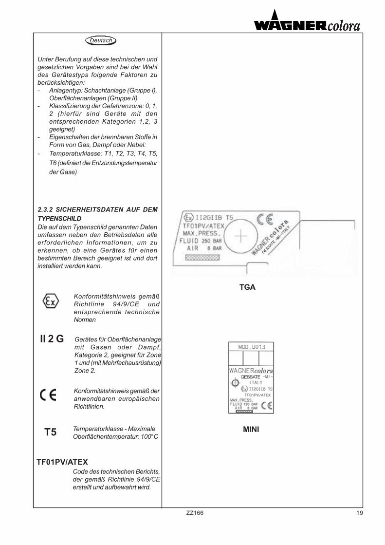
2.3.2 SICHERHEITSDATEN AUF DEMTYPENSCHILDDie auf dem Typenschild genannten Datenumfassen neben den Betriebsdaten alleerforderlichen Informationen, um zuerkennen, ob eine Gerätes für einenbestimmten Bereich geeignet ist und dortinstalliert werden kann.
Konformitätshinweis gemäßRichtlinie 94/9/CE undentsprechende technischeNormen
Gerätes für Oberflächenanlagemit Gasen oder Dampf,Kategorie 2, geeignet für Zone1 und (mit Mehrfachausrüstung)Zone 2.
Konformitätshinweis gemäß deranwendbaren europäischenRichtlinien.
Temperaturklasse - MaximaleOberflächentemperatur: 100°C
Code des technischen Berichts,der gemäß Richtlinie 94/9/CEerstellt und aufbewahrt wird.
II 2 G
T5
TF01PV/ATEX
TGA
MINI
GESSATE
GESSATE
20 ZZ166
2.3.3 RISCHIO D’INCENDIO EDESPLOSIONE
MESSA A TERRAL'apparecchiatura deve esserecollegata a terra mediante il fissaggiomeccanico della stessa (staffa disupporto o collettore del fluido)ponendo attenzione affinchè questocollegamento non sia soggetto adallentamento o svitamento.
Occorre prevenire la formazione dicariche elettrostatiche sulle tubazionidi collegamento, utilizzando dovenecessario tubo in materialeconduttivo.
REAZIONI ESOTERMICHEFluidi incompatibili con i materialidell'apparecchiatura o misceleparticolarmente reattive di prodotti apiù componenti, possono provocarereazioni esotermiche e svilupparetemperature o pressioni pericolose.Verificare anche la compatibilitàchimica tra fluido e materiali.
AVVERTENZE
• Temperatura di accensione delprodotto di verniciatura.La temperatura massima dellasuperficie della pistola dipendeessenzialmente dalla temperatura delprodotto di verniciatura.La pistola è adatta per fluidi ad unatemperatura massima di 80°C. Latemperatura di accensione delmateriale utilizzato deve esserealmeno 15° K sopra la temperatura dilavoro.
• Temperatura ambiente ammissibile.-20°C a +40°C
EXOTHERMIC REACTIONSFluids incompatible with theequipment’s materials or particularlyreactive mixtures of products withseveral components may causeexothermic reactions and developdangerous temperatures or pressure.Also check the chemical compatibilityof the fluid and materials.
REACTIONS EXOTHERMIQUESLes fluides incompatibles avec lesmatériaux de l'appareillage ou lesmélanges particulièrement réactivesde produits à plusieurs composantspeuvent provoquer des réactionsexothermiques et développer destempératures ou des pressionsdangereuses.Vérifier aussi la compatibilitéchimique entre fluide et matériaux.
• Ignition temperature of the coatingmaterial.The maximum surface temperature ofthe gun depends essentially on thetemperature of the coating material.The gun is suitable for coatingmaterials with a maximumtemperature of 80°C. The ignitiontemperature of the coating materialmust be at least 15K above theworking temperature.
• Permissible ambient temperature.-20°C to +40°C
2.3.3 FIRE AND EXPLOSIONHAZARD
EARTHINGThe equipment must be put to earthby mechanic fixing (supportingbracket or fluid manifold), payingattention that this connection is notsubject to loosening or unscrewing.
Avoid all electrostatic charges onconnecting pipes, using a pipe inconductive material where necessary.
2.3.3 RISQUE D'INCENDIE ETD'EXPLOSION
MISE A LA TERREL’équipement doit être connecté à laterre à travers sa fixation mécanique(bride de support ou collecteur dufluide) : vérifier que cette connexionn’est pas desserrée ou dévissée.
Il faut éviter la formation de chargesélectrostatiques sur les tuyaux deconnexion, en utilisant, le caséchéant, un tuyau en matérielconductible.
• Température d’inflammation duproduit de vernissage.La température max. de la surface dupistolet dépend essentiellement de latempérature du produit de vernissage.Le pistolet est indiqué pour des fluidesayant une température max. de 80°C.La température d’inflammation dumatériel utilisé doit être au moins 15°Kau-dessus de la température detravail.
• Température ambiante acceptable:de -20°C à +40°C
WARNING AVERTISSEMENTS
21ZZ166
EXOTHERME REAKTIONENFlüssigkeiten, die mit denGerätesmaterialien nicht kompatibel sindoder besonders reaktive Mischungen ausverschiedenen Komponenten könnenexotherme Reaktionen hervorrufen und hoheTemperaturen oder gefährliche Druckwerteentwickeln.Prüfen Sie auch die chemischeKompatibilität zwischen Flüssigkeit undMaterialien.
• Zündtemperatur desBeschichtungsstoffes.Die maximale Oberflächentemperatur derPistole hängt im wesentlichen von derTemperatur des Beschichtungsstoffes ab.Die Pistole ist für Beschichtungsstoffe miteiner maximalen Temperatur von 80°Cgeeignet. Die Zündtemperatur desBeschichtungsstoffes muss mindestens15K über der Verarbeitungstemperaturliegen.
• Zulässige Umgebungstemperatur.-20°C bis +40°C
2.3.3 BRAND- UNDEXPLOSIONSGEFAHR
ERDUNGDas Gerät ist durch eine mechanischeFixierung an den Boden zu befestigen(Trägerbügel oder Flüssigkeitssammler).Dabei ist darauf zu achten, dass sich dieseBefestigung nicht lockert oder aufdreht.
Das Entstehen von elektrostatischemAufladen auf den Anschlussleitungen ist zuvermeiden, indem an den erforderlichenStellen leitfähiges Rohrmaterial verwendetwird.
WARNUNG
22 ZZ166
• Contatto con acciaio o ferro ossidato.Le scintille di origine meccanica sonouna fonte di accensione, che deveessere evitata (colpi o urti). Il contattocon acciaio e ferro ossidato el’intervento sull’apparecchiatura conattrezzi, in particolare quelli d’acciaio,deve essere evitato in presenza diatmosfera potenzialmente esplosiva.
• Pulizia per mantenere conduttrice lasuperficie.Un aspetto essenziale dellaprotezione dalle esplosioni è laconducibilità elettrica superficialedell’apparecchiatura. Pertanto essadeve essere pulita frequentemente. Idepositi sulla superficie, che riduconola conducibilità, devono essererimossi.
• Contact with steel or rusty iron.Mechanical sparks are a source ofignition , which must be avoided(impacts, blows).Contact with steel orrusty iron, and working with tools,particularly steel ones, is onlypermissible if no explosiveatmosphere is present.
• Cleaning to maintain the conductivesurface.A component part of the explosionprotection is the continuousconductivity of the gun. So clean afterevery use. Surface deposits, whichreduce the conductivity, are to beremoved.
• Contact avec acier ou fer oxydé.Les étincelles d’origine mécaniquereprésentent une sourced’inflammation qu’il faut éviter (coupsou chocs). En présence d’uneatmosphère potentiellementexplosive, il faut éviter le contact avecl’acier et le fer oxydé ainsi que lesinterventions sur l’équipement avecd’outillages, notamment ceux en acier.
• Nettoyage pour garder laconductivité de la surface.Un aspect essentiel de la protectioncontre les explosions est laconductivité électrique de la surfacede l’équipement. Il faut donc lanettoyer souvent, en enlevant lesdépôts sur la surface qui réduisent laconductivité électrique de la surface.
23ZZ166
• Kontakt mit Stahl oder rostigem EisenMechanische Funken als Zündquelle sindzu vermeiden (Schlagen, Stossen). DerKontakt mit Stahl oder rostigem Eisen,sowie das Arbeiten mit Werkzeugen,insbesondere aus Stahl, ist nur zulässig,wenn keine explosionsfähige Atmosphärebesteht.
• Reinigung zur Erhaltung der leitfähigenOberfläche.Bestandteil des Explosionsschutzes ist diedurchgehende Leitfähigkeit der Pistole.Oberflächenablagerungen, welche dieLeitfähigkeit herabsetzen, sind zuentfernen.
24 ZZ166
3. DESCRIZIONE ECARATTERISTICHETECNICHE
Pistola o valvola per intercettazionefluidi o per applicazioni in AIRLESS.
NOTA Questa pistola può essereutilizzata con la maggior parte deicomuni materiali per verniciatura erifinitura. Ad ogni modo, se usata conmateriali corrosivi o abrasivi, éprevedibile che saranno necessarifrequenti e accurati lavaggi e/o sipresenterà la necessità di sostituirepiù frequentemente alcuni pezzi. Sedovessero esserci dubbi sullapossibilità di utilizzare la pistola conun particolare materiale, éconsigliabile farci sapere qualemateriale deve essere utilizzato osottoporci un campione peresaminarlo.
3. DESCRIPTION ANDTECHNICALCHARACTERISTICSDESCRIPTION
Gun or valve for fluids cut-off or forAIRLESS applications.
NOTE This gun can be used with mostof the common coating and finishingproducts. Anyway, if the gun is usedwith corrosive or abrasive products,frequent and careful washing will benecessary and/or some pieces will needto be replaced more frequently. If anydoubt should arise on the possibilityto use the gun with a particular product,please let us know what material isgoing to be used or send us a sampleto be examined.
3. DESCRIPTION ETC A R A C T E R I S T I Q U E STECHNIQUES
Pistolet ou valve d'arrêt fluides ou pourapplications AIRLESS.
REMARQUE: Ce pistolet peut êtreutilisé avec la plupart des matériauxemployés habituellement pour lapeinture et le finissage. Quoi qu’il ensoit, si on l’utilise avec des produitscorrodants ou abrasifs, il estnécessaire d’envisager desnettoyages fréquents et méticuleux et,si besoin est, de remplacer plusfréquemment certaines pièces. En casde doutes quant à la possibilitéd’utiliser le pistolet avec un certaintype de produit, il est conseillé de nousfaire savoir quel est le produit que l’onenvisage d’utiliser et de nous faireparvenir un échantillon afin que nousl’examinions.
25ZZ166
3. BESCHREIBUNG DER ANLAGEUND TECHNISCHE DATEN
Spritzpistole oder Ventil für dieFlüssigkeitsperre oder fürAirlessanwendungen.
Hinweis: Diese Spritzpistole kann für diemeisten gängigen Lackier- undFinishprodukte benutzt werden. BeiVerwendung von aggressiven Produkten istes nötig, die Anlage häufig gründlich zuspülen und/oder einzelne Komponentenöfter zu ersetzen. Sollten Sie Zweifel überden möglichen Einsatz eines Produktenhegen, so wenden Sie sich bitte an Wagnercolora S.r.l. Geben Sie dabei die Art desProduktes an oder senden Sie ein Musterein.
26 ZZ166
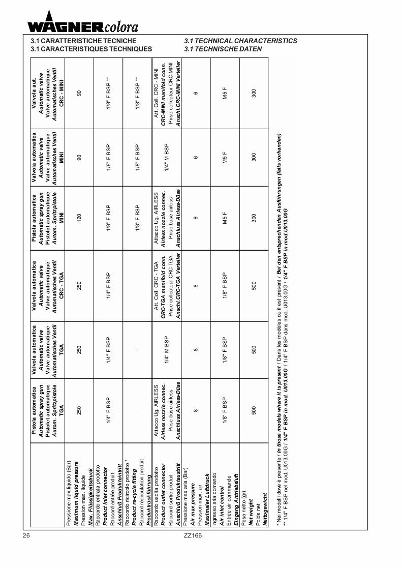
3.1 CARATTERISTICHE TECNICHE 3.1 TECHNICAL CHARACTERISTICS3.1 CARACTERISTIQUES TECHNIQUES 3.1 TECHNISCHE DATEN
Pis
tola
aut
omat
ica
Valv
ola
auto
mat
ica
Val
vola
aut
omat
ica
Pist
ola
auto
mat
ica
Val
vola
aut
omat
ica
Val
vola
aut
.A
utom
atic
spr
ay g
unA
utom
atic
val
veA
utom
atic
val
veA
utom
atic
spr
ay g
unA
utom
atic
val
veA
utom
atic
val
veP
isto
let a
utom
atiq
ueV
alve
aut
omat
ique
Val
ve a
utom
atiq
ueP
isto
let a
utom
atiq
ueV
alve
aut
omat
ique
Val
ve a
utom
atiq
ueA
utom
. Spr
itzpi
stol
eA
utom
atis
ches
Ven
til
Aut
omat
isch
es V
entil
A
utom
. Spr
itzpi
stol
eA
utom
atis
ches
Ven
til
Aut
omat
isch
es V
entil
TG
ATG
ACR
C -
TGA
MIN
IM
INI
CRC
- M
INI
Pres
sion
e m
ax li
quid
o (B
ar)
Max
imum
liqu
id p
ress
ure
Pres
sion
max
. liq
uide
Max
. Flü
ssig
keits
druc
kRa
ccor
do e
ntra
ta p
rodo
ttoPr
oduc
t inl
et c
onne
ctor
Racc
ord
entré
e pr
odui
tA
nsch
luß
Prod
ukte
intri
ttRa
ccor
do ri
circ
olo
prod
otto
*Pr
oduc
t re-
cycl
e fit
ting
Racc
ord
réci
rcul
atio
n pr
odui
t Pr
oduk
trück
führ
ung
Racc
ordo
usc
ita p
rodo
ttoA
ttacc
o U
g. A
IRLE
SS
Att.
Col
l. C
RC
- TG
AAt
tacc
o U
g. A
IRLE
SS
Att.
Col
l. C
RC
- M
INI
Prod
uct o
utle
t con
nect
orA
irles
s no
zzle
con
nec.
C
RC-
TGA
man
ifold
con
n.
Air
less
noz
zle
conn
ec.
CR
C-M
INI m
anifo
ld c
onn.
Ra
ccor
d so
rtie
prod
uit
Pris
e bu
se a
irles
sP
rise
colle
cteu
r CRC
-TG
AP
rise
buse
airl
ess
Pris
e co
llect
eur C
RC-
MIN
IA
nsch
luß
Prod
ukta
ustr
ittA
nsch
luss
Air
less
-Düs
eA
nsch
l.CR
C-T
GA
Ver
teile
rA
nsch
luss
Air
less
-Düs
eA
nsch
l.CR
C-M
INI V
erte
iler
Pres
sion
e m
ax a
ria (B
ar)
Air
max
pre
ssur
ePr
essi
on m
ax. a
irM
axim
aler
Luf
tdru
ckIn
gres
so a
ria c
oman
doA
ir in
let c
ontr
olEn
trée
air c
omm
ande
Eing
ang
Ant
rieb
sluf
tPe
so n
etto
(gr)
Net w
eigh
tPo
ids
net
Netto
gew
icht
* Nei
mod
elli
dove
è p
rese
nte
/ In
thos
e m
odel
s w
here
it is
pre
sent
/ D
ans
les
mod
èles
où
il es
t pré
sent
/ Be
i den
ent
spre
chen
den
Aus
führ
unge
n (fa
lls v
orha
nden
) **
1/4
" F
BS
P n
el m
od. U
013.
00G
/ 1/
4" F
BSP
in m
od. U
013.
00G
/ 1/
4" F
BS
P da
ns m
od. U
013.
00G
/ 1/
4" F
BSP
in m
od.U
013.
00G
250
120
9090
1/4"
F B
SP
1/4"
F B
SP1/
4" F
BS
P1/
8" F
BS
P1/
8" F
BS
P1/
8" F
BS
P **
250
250
1/4"
M B
SP
1/4"
M B
SP
--
-1/
8" F
BS
P
86
1/8"
F B
SP
1/8"
F B
SP
**
66
1/8"
F B
SP
1/8"
F B
SP1/
8" F
BS
PM
5 F
M5
FM
5 F
88
300
300
500
500
500
300
27ZZ166
PAGINA LASCIATA INTENZIONALMENTE VUOTAPAGE LEFT INTENTIONALLY BLANKPAGE LAISSEE EN BLANCLEERSEITE
28 ZZ166
3.3 RICAMBI
Per mantenere in efficienza la pistolaé preferibile dotarsi di ricambiconsigliati per un primo intervento.
- Serie guarnizioni- Ago
3.4 MESSA FUORI SERVIZIO
Lo smaltimento sia dei prodottiutilizzati ( vernici, solventi, ecc.) chedella pistola, all’atto della sua messafuori servizio, devono essere effettuatisecondo la vigente normativa.
3.5 IMMAGAZZINAMENTO
L’apparecchiatura viene consegnatanella sua confezione, è consigliabilemantenerla in luogo chiuso non umido.Se si prevede di non utilizzare lapistola per un lungo periodo, al terminedel lavoro, effettuare un accuratolavaggio.
3.5 STORAGE
The equipment is delivered in itspackaging. It is highly recommendedto store it in a closed, dry place. Ifyou foresee not to use the gun for along period, wash ‘it carefully after thework.
3.4 EQUIPMENT DISMANTLING
When dismantling the gun, both theproducts used (paints, solvents etc.)and the gun itself, must be disposedof according to the regulations in force
3.3 SPARE PARTS
In order to keep the gun in a goodworking condition, it would be betterto stock the spare parts suggestedfor a first intervention.- Gasket set- Needle
3.3 PIECES DE RECHANGE
Pour garantir l’efficacité du pistolet, ilest préférable de prévoir les piècesde rechange conseillées pour unepremière intervention d’urgence.
- Jeu de joints- Aiguille
3.4 MISE AU REBUT
La mise au rebut des produits utilisés(peintures, solvants, etc.) et dupistolet, au moment de sa mise horsservice, doit être effectuéeconformément aux normes en vigueur.
3.5 STOCKAGE
L’appareil est livré dans sonemballage. Il est conseillé de lestocker dans un lieu clos et nonhumide. Si l’on envisage de ne pasutiliser le pistolet pendant une longuepériode, effectuer un nettoyageminutieux à la fin du travail.
3.2 RUMOROSITA’
II livello di rumorosità delle pistole éin funzione dell’ugello utilizzato e dellapressione del liquido spruzzato.(Comunque < 80 dbA)
3.2 NOISE LEVEL
Guns noise level depends on thenozzle used and on the pressure ofthe liquid sprayed.(Always < 80 dbA)
3.2 NUISANCE SONORE
Le niveau de bruit émis par lespistolets dépend de la buse qui estutilisée et de la pression du liquidepulvérisé.(Toujours < 80 dbA)
29ZZ166
3.3 ERSATZTEILE
Um die Betriebsbereitschaft der Anlagesicherzustellen, empfiehlt sich dieVorhaltung folgender Ersatzteile für einenspäteren Austausch:
- Einen Satz Dichtungen- Eine Nadel
3.4 STILLEGUNG
Die Entsorgung sowohl der verwandtenProdukte (Lacke, Lösungsmittel usw.) alsauch der stillgelegten Spritzpistole mußgemäß den geltenden Vorschriften erfolgen.
3.5 LAGERUNG
Die Anlage wird in ihrer Verpackungangeliefert und sollte an einemgeschlossenen und trockenen Ort gelagertwerden. Wenn die Anlage voraussichtlich fürlängere Zeit nicht benutzt wird, so spülenSie sie nach Beendigung der Lackierarbeitensorgfältig.
3.2 SCHALLPEGEL
Der Schallpegel beim Betrieb derSpritzanlage hängt von der benutztenSpritzdüse und dem Druck der gespritztenFlüssigkeit ab (in jedem Fall jedoch <80dbA).
30 ZZ166
4.2 MANUTENZIONE
Modello MINI
Serraggio guarnizionepremistoppa.
1) Scaricare completamente lapressione nell' apparecchiatura
2) Serrare con moderazione la vitepremistoppa, inserendo una spina didiametro adeguato nei fori della vitestessa.
ATTENZIONE:
Prima di iniziare le operazioni dimanutenzione o puliziaintercettare l'alimentazione delprodotto e scaricare la pressionedell' apparecchiatura.Intercettare l'aria comandopistola.
1) Scollegare le tubazioni delprodotto e dell'aria di comando edasportare la pistola dal supporto.
4. PULIZIA E MANUTENZIONE
4.1 PULIZIA
La pulizia é indispensabile perottenere buoni risultati. Al termine dellavoro e al cambio del fluido o delcolore la pistola, e i componenti adessa connessi devono essere lavaticon cura. I materiali utilizzati nellacostruzione di questa pistola sono(tenendo presenti le avvertenze sugliIdrocarburi Alogenati) resistenti aisolventi, escluse le guarnizioni dellasezione pneumatica di comando.Mai immergere la pistolacompletamente nel solvente.
I solventi utilizzati per lavaggio devonoessere regolarmente controllati perassicurarsi che la pistola non venga acontatto con prodotti alterati odecomposti.
4. NETTOYAGE ET ENTRETIEN
4.1 NETTOYAGE
Le nettoyage est indispensable si l’onveut obtenir de bons résultats. A la findu travail et lors du changement defluide ou de couleur, le pistolet et lescomposants qui lui sont raccordésdoivent être lavés avec soin. Lesmatériaux utilisés pour la fabricationde ce pistolet sont (compte tenu desavertissements sur les HydrocarburesHalogénés) résistants aux solvants, àl’exclusion de la partie pneumatiquede commande.Ne jamais plonger complètement lepistolet dans du solvant.
Les solvants utilisés pour le lavagedoivent être contrôlés régulièrementde manière à s’assurer que le pistoletne soit pas en contact avec desproduits altérés ou décomposés.
4.2 ENTRETIEN
Modèle MINI
Serrage du joint presse-étoupe.
1) Purger complètement l’appareil dela pression qu’il renferme.
2) Serrer modérément la vis presse-étoupe, en insérant une goupilleprésentant un diamètre approprié dansles trous de la vis.
ATTENTION:
Avant d’entreprendre lesopérations d’entretien ou denettoyage, fermer l’alimentationdu produit et décharger la pressionde l’appareil.Bloquer l’air de commande dupistolet.
1) Détacher les tuyaux du produitet de l’air de commande et ôter lepistolet de son support.
4.1 . CLEANING
Cleaning is essential to obtain goodresults. At the end of the work andwhen changing the fluid or the colour,the gun, the filter and the relevantcomponents must be carefullywashed. The materials used tomanufacture this gun (keeping in mindthe recommendations on thehalogenated hydrocarbons) aresolvent resistant, with the exceptionof the compressed air seals.Never fully immerse the gun insolvents.
The solvents used for washing mustbe regularty controlled to make surethat the gun does not come in contactwith altered or decomposed products.
4.2 MAINTENANCE
Model MINI
Tightening the packing seal
1)Discharge air pressure from theequipment completely
2)Tighten the gland screw (do notover-tighten) by inserting a pin ofsuitable diameter into the holes of thescrew barrel.
CAUTION
Before maintenance or cleaningoperations, shut off the productfeed and discharge air pressurefrom the equipment.Close the air shut-off valve.
1)Disconnect the product andcompressed air lines, and remove thegun from its support.
4. CLEANING ANDMAINTENANCE
31ZZ166
4. REINIGUNG UND WARTUNG
4.1 REINIGUNG
Eine sorgfältige Reinigung ist unerläßlich, umbeste Resultate zu erzielen. NachBeendigung der Arbeit oder bei einem Lack-oder Lackfarbenwechsel müssen dieSpritzpistole und daran angeschlosseneKomponenten sorgfältig gespült werden. Diebei der Herstellung dieser Spritzpistoleverwandten Werkstoffe (abgesehen von denEinschränkungen betr. halogenierteKohlenwasserstoffe) sind, bis auf dieDichtungen der pneumatischen Steuereinheit,lösungsmittelbeständig.
Die zum Spülen benutzten Lösungsmittelmüssen regelmäßig kontrolliert werden, umsicherzustellen, daß die Spritzpistole nichtmit veränderten oder zersetzten Produktenin Kontakt kommt.
4.2 WARTUNG
Modelle MINI
Festmachen der Stopfbuchsendichtung
1) Lassen Sie den Druck in der Anlage ab.
2) Ziehen Sie die Schraube der Stopfbuchsean (nicht zu fest!), indem Sie einenSpannstift mit geeignetem Durchmesser indie Schraubenöffnungen einführen.
ACHTUNG:
Unterbrechen Sie vor Beginn derReinigungs- oder Wartungsarbeiten dieProduktzufuhr und lassen Sie dieDruckluft aus der Anlage ab.Unterbrechen Sie die Zufuhr derSpritzpistolen-Steuerluft.
1) Schließen Sie die Produkt- undSteuerluftzufuhr und nehmen Sie dieSpritzpistole aus ihrer Halterung.
32 ZZ166
- procedere al montaggio dei nuoviparticolari avendo cura di serrarela vite premistoppa (1) solo dopoavere riassemblato la pistola.
3) Sostituzione guarnizioni edago:
- procedere come descritto al punto2 per la sostituzione dellaguarnizione premistoppa;
- asportare le 4 viti di unione fracorpo valvola (6) e coperchio (7)quindi estrarre il gruppo pistone/ago;
- serrare in morsa il codolo delpistone (8), mediante adattimorsetti morbidi per nondanneggiarlo, quindi smontare lavite (12) ed estrarre l'ago;
- inserire il nuovo ago e rimontare lavite (12), impiegando pocosigillante (loctite), avendo cura dinon bloccare l'ago che deve poteroscillare senza eccessivo giocoassiale;
- sostituire le guarnizioni (14-13)con le nuove preventivamentelubrificate con grasso;
- procedere al rimontaggio dellapistola.
4) Sostituzione testa valvola:- asportare le 4 viti di unione fra
flangia (9) e corpo valvola (6)estrarre la testa valvola (15) esostituirla con la nuova.
NB: qualora si rendesse necessariala sostituzione della testa valvola saràopportuna anche la sostituzionedell'ago (veder punti 2-3).
2) Sostituzione guarnizionepremistoppa:
- allentare la vite premistoppa (1)ruotandola in senso antiorario;
- asportare le 4 viti di unione fraflangia (9) e corpo valvola (6)quindi sfilare l'ago dalla testavalvola allontanando questa dalcorpo;
- asportare la vite premistoppa eprocedere all'estrazione dell'anellopremistoppa (3), della guarnizione(10) e del reggispinta (4),avvalendosi di un attrezzo adatto(allo scopo può essere utilizzatauna vite autofilettante da inserirenella guarnizione (10) );
2) Remplacement du joint presse-étoupe:- desserrer la vis presse-étoupe (1)
en la tournant dans le sens inverseà celui des aiguilles d’une montre;
- enlever les 4 vis qui unissent labride (9) et le corps de la soupape(6); dégager l’aiguille de la tête desoupape et éloigner la tête ducorps;
- enlever la vis presse-étoupe etretirer la bague presse-étoupe (3),le joint (10) et le palier de butée(4), en se servant d’un outil prévuà cet effet (il est possible d’utiliserune vis auto-taraudeuse et del’insérer dans le joint (10));
- Procéder au montage desnouveaux détails en soignant debien serrer la vis presse-étoupe (1)seulement après avoir remonté lepistolet.
3) Remplacement des joints et del’aiguille:- suivre la démarche indiquée par le
paragraphe 2 pour leremplacement du joint presse-étoupe;
- enlever les 4 vis qui unissent lecorps de soupape (6) et lecouvercle (7); enlever le groupepiston/aiguille;
- serrer la queue du piston (8) dansdes étaux suffisamment souplespour ne pas l’endommager,démonter la vis (12) et ôterl’aiguille;
- insérer la nouvelle aiguille etremonter la vis (12),en utilisant unpeu de scellant (loctite) et enveillant à ne pas bloquer l’aiguillequi doit être à même d’oscillersans avoir trop de jeu axial;
- remplacer les joints (14-13) avecdes joints neufs qu’on aura prissoin de graisser au préalable;
- remonter le pistolet.4) Remplacement de la tête desoupape:- enlever les 4 vis qui unissent la
bride (9) et le corps de soupape(6);ôter la tête de soupape (15) etla remplacer par une neuve.
NB: s’il s’avère nécessaire deremplacer la tête de soupape, il estégalement nécessaire de remplacerl’aiguille (voir paragraphes 2-3).
2) Replacing the gland gasket:
- slacken the gland screw (1) byturninganti-clockwise;- remove the 4 screws securing theflange (9) to the valve body (6), thenwithdraw the needle from the valvehead by distancing the head from thevalve body;- remove the gland screw, thenproceed to withdraw the packing gland(3), the packing (10) and finally thethrust collar (4) using suitable tools (aself-tapping screw can be driven intothe packing (10) and used as a puller);- fit the new parts, taking care totighten the gland screw (1) once thegun is reassembled.
3) Replacing the needle andgaskets:- proceed as described at point n°2for the replacement of the packing;- remove the 4 screws securing thevalve body (6) to the cover (7) andremove the piston/needle assembly;- clamp the piston rod (8) in a vice,which should have soft faced jaws toavoid damage;undo the screw (12)and remove the needle;- insert the new needle and retightenthe screw (12). Apply a threadlocker(loctite) sparingly. Ensure the needleis not overtightened; it must be free tooscillate without excessive axial play;-grease the new seals (14-13), and fitin the respective grooves;- reassemble the gun.
4) Replacing the valve head:- remove the 4 screws securing theflange (9) to the valve body (6),remove the valve head (15) andreplace it with a new one.
N.B. When replacing the valve head,it is advisable to replace the needleas well (see points 2-3).
33ZZ166
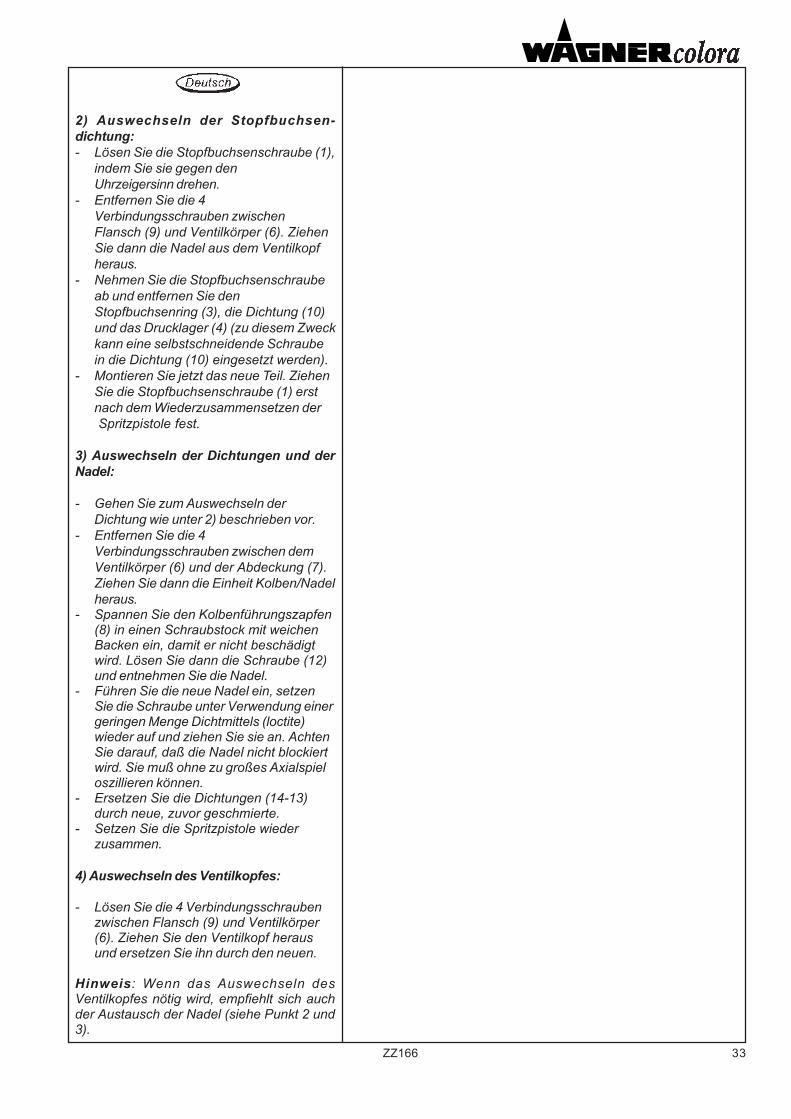
2) Auswechseln der Stopfbuchsen-dichtung:- Lösen Sie die Stopfbuchsenschraube (1),
indem Sie sie gegen denUhrzeigersinn drehen.
- Entfernen Sie die 4Verbindungsschrauben zwischenFlansch (9) und Ventilkörper (6). ZiehenSie dann die Nadel aus dem Ventilkopfheraus.
- Nehmen Sie die Stopfbuchsenschraubeab und entfernen Sie denStopfbuchsenring (3), die Dichtung (10)und das Drucklager (4) (zu diesem Zweckkann eine selbstschneidende Schraubein die Dichtung (10) eingesetzt werden).
- Montieren Sie jetzt das neue Teil. ZiehenSie die Stopfbuchsenschraube (1) erstnach dem Wiederzusammensetzen der Spritzpistole fest.
3) Auswechseln der Dichtungen und derNadel:
- Gehen Sie zum Auswechseln derDichtung wie unter 2) beschrieben vor.
- Entfernen Sie die 4Verbindungsschrauben zwischen demVentilkörper (6) und der Abdeckung (7).Ziehen Sie dann die Einheit Kolben/Nadelheraus.
- Spannen Sie den Kolbenführungszapfen(8) in einen Schraubstock mit weichenBacken ein, damit er nicht beschädigtwird. Lösen Sie dann die Schraube (12)und entnehmen Sie die Nadel.
- Führen Sie die neue Nadel ein, setzenSie die Schraube unter Verwendung einergeringen Menge Dichtmittels (loctite)wieder auf und ziehen Sie sie an. AchtenSie darauf, daß die Nadel nicht blockiertwird. Sie muß ohne zu großes Axialspieloszillieren können.
- Ersetzen Sie die Dichtungen (14-13)durch neue, zuvor geschmierte.
- Setzen Sie die Spritzpistole wiederzusammen.
4) Auswechseln des Ventilkopfes:
- Lösen Sie die 4 Verbindungsschraubenzwischen Flansch (9) und Ventilkörper(6). Ziehen Sie den Ventilkopf herausund ersetzen Sie ihn durch den neuen.
Hinweis: Wenn das Auswechseln desVentilkopfes nötig wird, empfiehlt sich auchder Austausch der Nadel (siehe Punkt 2 und3).
34 ZZ166
Modello TGA
Serraggio guarnizionepremistoppa.
1) Scaricare completamente lapressione nell' apparecchiatura
2) Serrare con moderazione la vitepremistoppa, inserendo una spina didiametro adeguato nei fori della vitestessa.
ATTENZIONE:
Prima di iniziare le operazioni dimanutenzione o puliziaintercettare l'alimentazione delprodotto e scaricare la pressionedell' apparecchiatura.Intercettare l'aria comandopistola.
1) Scollegare le tubazioni delprodotto e dell'aria di comando edasportare la pistola dal supporto.
2) Sostituzione guarnizionepremistoppa:(Vedi dis.pag.35)
- allentare la vite premistoppa (1)ruotandola in senso antiorario;
- togliere il coperchio (4) svitandolo,sfilare il pistone (3) con l'ago (2)dal corpo dell'apparecchio;
- asportare la vite premistoppa eprocedere all'estrazione di:- distanziale premistoppa (dovepresente)- anello (7)- guarnizione (11)- reggispinta o ranella (8) (secondoi modelli)avvalendosi di un attrezzo adatto(allo scopo può essere utilizzatauna vite autofilettante da inserirenella guarnizione (11))
- procedere al montaggio dei nuoviparticolari avendo cura di serrarela vite premistoppa (1) solo dopoavere riassemblato la pistola.
Model TGA
Tightening the packing seal
1)Discharge air pressure from theequipment completely
2)Tighten the gland screw (do not over-tighten) by inserting a pin of suitablediameter into the holes of the screwbarrel.
CAUTION
Before maintenance or cleaningoperations, shut off the productfeed and discharge air pressurefrom the equipment.Close the air shut-off valve.
1)Disconnect the product andcompressed air lines, and remove thegun from its support.
2) Replacing the gland gasket:(Refer drawing page 35)- slacken the gland screw (1) byturning anti-clockwise;- remove the cover (4) unscrewing it,remove the piston (3) with the needle(2) from the equipment body;- remove the packing gland screwand take out:
- packing gland spacer (if any)- ring (7)- gasket (11)- thrust block or washer (8)(according to the models)
using suitable tools (a self-tappingscrew can be driven into the packing(11) and used as a puller);- fit the new parts, taking care totighten the gland screw (1) once thegun is reassembled.
Modèle TGA
Serrage du joint presse-étoupe.
1) Purger complètement l’appareil dela pression qu’il renferme.
2) Serrer modérément la vis presse-étoupe, en insérant une goupilleprésentant un diamètre appropriédans les trous de la vis.
ATTENTION:
Avant d’entreprendre lesopérations d’entretien ou denettoyage, fermer l’alimentationdu produit et décharger lapression de l’appareil.Bloquer l’air de commande dupistolet.
1) Détacher les tuyaux du produit etde l’air de commande et ôter le pistoletde son support.
2) Remplacement du joint presse-étoupe:(Voir schéma page 35)- desserrer la vis presse-étoupe (1)
en la tournant dans le sens inverseà celui des aiguilles d’une montre;
- enlever le couvercle (4) en ledévissant, enlever le piston (3)avec le pointeau (2) du corps del’équipement;
- enlever la vis presse-étoupe etcontinuer avec l’extraction de:- entretoise presse-étoupe(lorsque présent)- bague (7)- joint (11)- contre-bague ou rondelle (8)(selon les modèles)en se servant d’un outil prévu à ceteffet (il est possible d’utiliser unevis auto-taraudeuse et de l’insérerdans le joint (11));
- Procéder au montage desnouveaux détails en soignant debien serrer la vis presse-étoupe (1)seulement après avoir remonté lepistolet.
35ZZ166
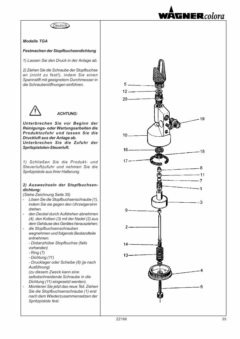
Modelle TGA
Festmachen der Stopfbuchsendichtung
1) Lassen Sie den Druck in der Anlage ab.
2) Ziehen Sie die Schraube der Stopfbuchsean (nicht zu fest!), indem Sie einenSpannstift mit geeignetem Durchmesser indie Schraubenöffnungen einführen.
ACHTUNG:
Unterbrechen Sie vor Beginn derReinigungs- oder Wartungsarbeiten dieProduktzufuhr und lassen Sie dieDruckluft aus der Anlage ab.Unterbrechen Sie die Zufuhr derSpritzpistolen-Steuerluft.
1) Schließen Sie die Produkt- undSteuerluftzufuhr und nehmen Sie dieSpritzpistole aus ihrer Halterung.
2) Auswechseln der Stopfbuchsen-dichtung:(Siehe Zeichnung Seite 35)- Lösen Sie die Stopfbuchsenschraube (1),
indem Sie sie gegen den Uhrzeigersinndrehen.
- den Deckel durch Aufdrehen abnehmen(4), den Kolben (3) mit der Nadel (2) ausdem Gehäuse des Gerätes herausziehen;
- die Stopfbuchsenschraubenwegnehmen und folgende Bestandteileentnehmen:- Distanzhülse Stopfbuchse (fallsvorhanden)- Ring (7)- Dichtung (11)- Drucklager oder Scheibe (8) (je nachAusführung)(zu diesem Zweck kann eineselbstschneidende Schraube in dieDichtung (11) eingesetzt werden).
- Montieren Sie jetzt das neue Teil. ZiehenSie die Stopfbuchsenschraube (1) erstnach dem Wiederzusammensetzen derSpritzpistole fest.
36 ZZ166
3) Sostituzione guarnizioni edago:
- procedere come descritto al punto2 per la sostituzione dellaguarnizione premistoppa;
- asportare il coperchio (4) quindiestrarre il gruppo pistone/ago;
- serrare in morsa il codolo delpistone (3), mediante adattimorsetti morbidi per nondanneggiarlo, quindi smontare lavite (14) ed estrarre l'ago;
- inserire il nuovo ago e rimontare lavite (14), impiegando pocosigillante (loctite), avendo cura dinon bloccare l'ago che deve poteroscillare senza eccessivo giocoassiale;
- sostituire le guarnizioni (16-17)con le nuove preventivamentelubrificate con grasso;
- procedere al rimontaggio dellapistola.
4) Sostituzione testa valvola:- svitare il nipplo completo (20) il
corpo sede ago (secondo i modelli)e sostituirlo con il nuovo.
NB: qualora si rendesse necessariala sostituzione della testa valvola saràopportuna anche la sostituzionedell'ago (veder punti 2-3).
3) Replacing the needle andgaskets:- proceed as described at point n°2for the replacement of the packing;- remove the cover (4) and remove thepiston/needle assembly;- clamp the piston rod (3) in a vice,which should have soft faced jaws toavoid damage;undo the screw (14)and remove the needle;- insert the new needle and retightenthe screw (14). Apply a threadlocker(loctite) sparingly. Ensure the needleis not overtightened; it must be freeto oscillate without excessive axialplay;-grease the new seals (16-17), and fitin the respective grooves;- reassemble the gun.
4) Replacing the valve head:- unscrew the complete nipple (20) theneedle seat (according to the models)and replace it with the new one
N.B. When replacing the valve head,it is advisable to replace the needleas well (see points 2-3).
3) Remplacement des joints et del’aiguille:- suivre la démarche indiquée par
le paragraphe 2 pour leremplacement du joint presse-étoupe;
- enlever le couvercle (4); enlever legroupe piston/aiguille;
- serrer la queue du piston (3) dansdes étaux suffisamment souplespour ne pas l’endommager,démonter la vis (14) et ôterl’aiguille;
- insérer la nouvelle aiguille etremonter la vis (14),en utilisant unpeu de scellant (loctite) et enveillant à ne pas bloquer l’aiguillequi doit être à même d’oscillersans avoir trop de jeu axial;
- remplacer les joints (16-17) avecdes joints neufs qu’on aura prissoin de graisser au préalable;
- remonter le pistolet.
4) Remplacement de la tête desoupape:- dévisser le nipple complet (20) le
corps siège pointeau (selon lesmodèles) et le remplacer avec lenouveau
NB: s’il s’avère nécessaire deremplacer la tête de soupape, il estégalement nécessaire de remplacerl’aiguille (voir paragraphes 2-3).
37ZZ166
3) Auswechseln der Dichtungen und derNadel:
- Gehen Sie zum Auswechseln derDichtung wie unter 2) beschrieben vor.
- den Deckel (4) wegnehmen und dann dieKolben/Nadel-Einheit herausnehmen
- Spannen Sie den Kolbenführungszapfen(3) in einen Schraubstock mit weichenBacken ein, damit er nicht beschädigtwird. Lösen Sie dann die Schraube (14)und entnehmen Sie die Nadel.
- Führen Sie die neue Nadel ein, setzenSie die Schraube (14) unter Verwendungeiner geringen Menge Dichtmittels(loctite) wieder auf und ziehen Sie siean. Achten Sie darauf, daß die Nadelnicht blockiert wird. Sie muß ohne zugroßes Axialspiel oszillieren können.
- Ersetzen Sie die Dichtungen (16-17)durch neue, zuvor geschmierte.
- Setzen Sie die Spritzpistole wiederzusammen.
4) Auswechseln des Ventilkopfes:
- den Nippel (20) mit den Nadelgehäuseentfernen (je nach Ausführung) und miteinem neuen Teil austauschen.
Hinweis: Wenn das Auswechseln desVentilkopfes nötig wird, empfiehlt sich auchder Austausch der Nadel (siehe Punkt 2 und3).
38 ZZ166
5. RICERCA GUASTI 5. TROUBLESHOOTING
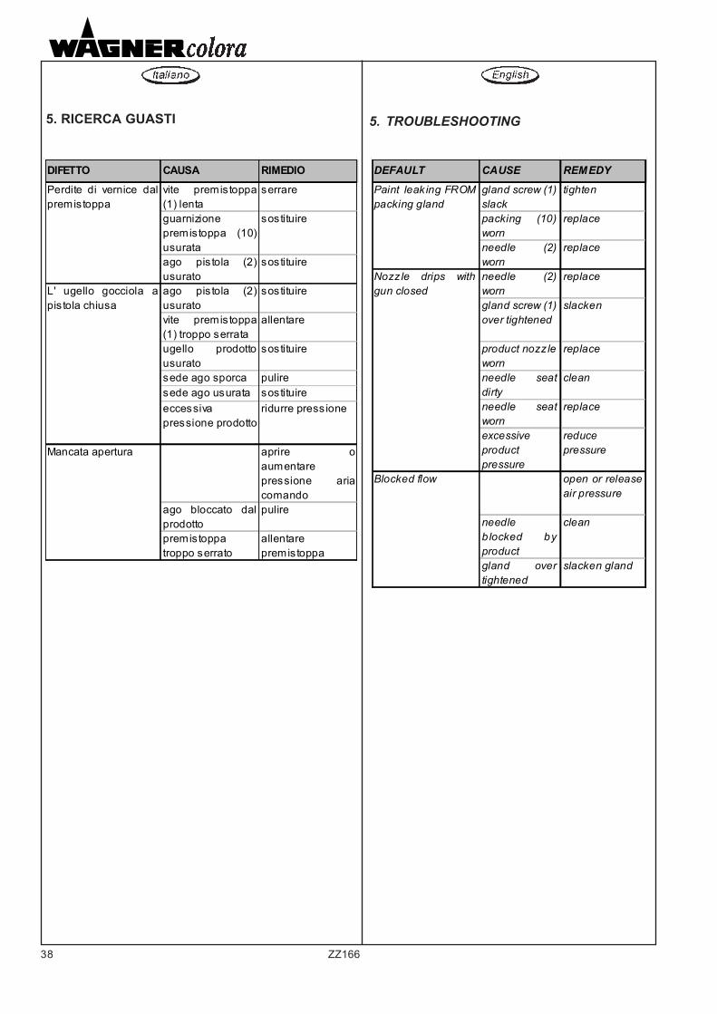
DIFETTO CAUSA RIMEDIOPerdite di vernice dalpremistoppa
vite premistoppa(1) lenta
serrare
guarnizione premistoppa (10)usurata
sostituire
ago pis tola (2)usurato
sostituire
L' ugello gocciola apis tola chiusa
ago pis tola (2)usurato
sostituire
vite premistoppa(1) troppo serrata
allentare
ugello prodottousurato
sostituire
sede ago sporca puliresede ago usurata sostituire eccessiva pressione prodotto
ridurre press ione
Mancata apertura aprire oaumentare pressione ariacomando
ago bloccato dalprodotto
pulire
premistoppa troppo serrato
allentare premistoppa
DEFAULT CAUSE REMEDY
Paint leak ing FROMpacking gland
gland screw (1) slack
tighten
packing (10)worn
replace
needle (2)worn
replace
Nozzle drips withgun closed
needle (2)worn
replace
gland screw (1) over tightened
slacken
product nozz leworn
replace
needle seatdirty
clean
needle seatworn
replace
excessive product pressure
reduce pressure
Blocked flow open or releaseair pressure
needle b locked byproduct
clean
gland overtightened
slacken gland
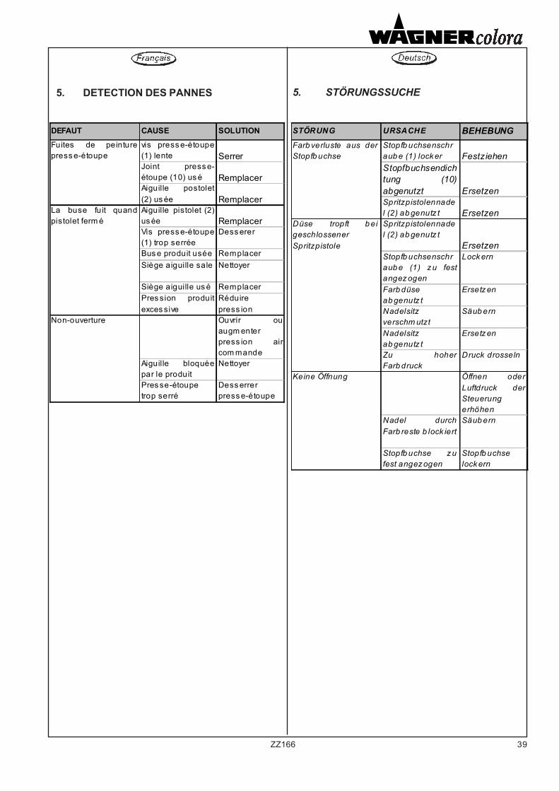
39ZZ166
5. DETECTION DES PANNES 5. STÖRUNGSSUCHE
DEFAUT CAUSE SOLUTION Fuites de peinturepress e-étoupe
vis press e-étoupe(1) lente SerrerJoint press e-étoupe (10) us é RemplacerAiguille postolet(2) us ée Remplacer
La buse fuit quandpistolet ferm é
Aiguille pistolet (2)us ée RemplacerVis press e-étoupe(1) trop serrée
Dess erer
Bus e produit usée RemplacerSiège aiguille sale Nettoyer
Siège aiguille us é RemplacerPres sion produitexces sive
Réduire press ion
Non-ouverture Ouvrir ouaugm enter press ion aircom mande
Aiguille bloquéepar le produit
Nettoyer
Pres se-étoupe trop serré
Dess errer press e-étoupe
STÖRUNG URSACHE BEHEBUNGFarb verluste aus derStopfb uchse
Stopfb uchsenschraub e (1) lock er FestziehenStopfbuchsendichtung (10)abgenutzt ErsetzenSpritzpistolennadel (2) ab genutz t Ersetzen
Düse tropft b eigeschlossener Spritzpistole
Spritzpistolennadel (2) ab genutz t
ErsetzenStopfb uchsenschraub e (1) z u festangez ogen
Lock ern
Farb düse ab genutz t
Ersetz en
Nadelsitz verschm utzt
Säub ern
Nadelsitz ab genutz t
Ersetz en
Zu hoherFarb druck
Druck drosseln
Keine Öffnung Öffnen oderLuftdruck derSteuerung erhöhen
Nadel durchFarb reste b lock iert
Säub ern
Stopfb uchse z ufest angez ogen
Stopfb uchse lock ern
40 ZZ166
6. CATALOGUE PIECES DERECHANGE
6. CATALOGO PARTI DIRICAMBIO
6. SPARE PARTSCATALOGUE
In order to find out exactly the requiredpart, it will be necessary to indicateto WAGNER colora the code andposition number of the part as shownon the cutaway view drawing herewithenclosed, as well as the partdescription.
In order to provide the best after-saleassistance, please be sure to supplyall the above mentioned informationwhen ordering spare parts, specifyingabove all the code number of themodeI.
Afin de repérer exactement le détaildésiré, l‘on devra communiquer aWAGNER colora le numéro de codeet de position du détail en objet,indiqués dans le dessin en section ci-joint, ainsi que la description de lapièce de rechange.
Afin d’assurer le meilleur serviceaprès-vente, I’on recommande defournir toutes les informationsdemandées ci-dessus, en spécifiantnotamment le numero de code dumodèle.
Al fine di individuare esattamente ilparticolare desiderato, il richiedentedeve comunicare alla WAGNERcolora il numero di codice e diposizione del particolare in oggettoriportati nel disegno in sezioneallegato a questo manuale,unitamente alla descrizione delricambio.
Allo scopo di fornire il migliore serviziopost-vendita, quando si ordinano leparti di ricambio, si prega di fornire tuttele indicazioni sopra richieste,specificando in particolare il numerodi codice del modello.
41ZZ166
6. ERSATZTEILE KATALOG
Der Antragsteller soll WAGNER colora dieKode- und Positionsnummer des Teiles, wiein der diesem Handbuch beiliegendenTeilschnittzeichnung gegeben, zusamrnenmit der Beschreibung des Ersatzteilesbestimmen , damit das gewünschte Stückgenau identifiziert werden kann.
Beim Bestellen von Ersatzteilen sollte jederder obengenannten Daten bestimmt werden,um das Nachmarkt-Dienst zu verbessern.Die Kode des Maschinenmodells solite auchangegeben werden.
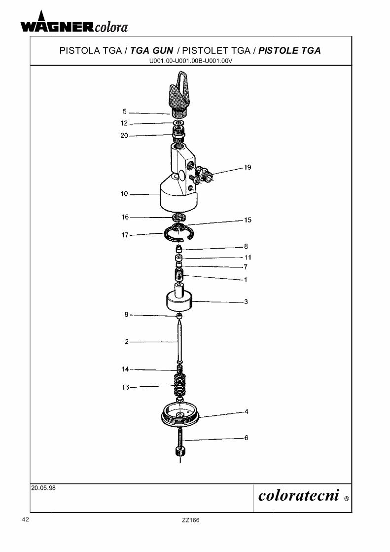
42 ZZ166
PISTOLA TGA / TGA GUN / PISTOLET TGA / PISTOLE TGAU001.00-U001.00B-U001.00V
20.05.98 coloratecni ®
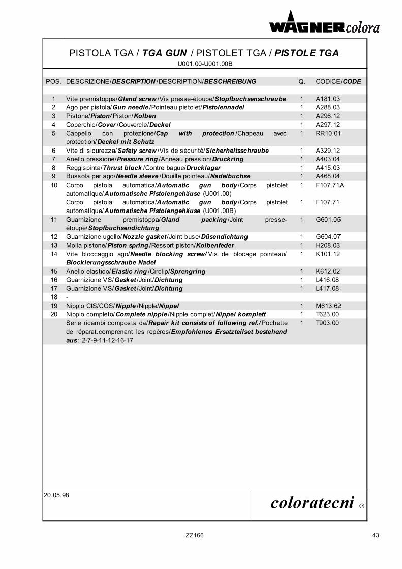
43ZZ166
PISTOLA TGA / TGA GUN / PISTOLET TGA / PISTOLE TGAU001.00-U001.00B
POS. DESCRIZIONE/DESCRIPTION /DESCRIPTION/BESCHREIBUNG Q. CODICE/CODE
1 Vite premistoppa/Gland screw /Vis presse-étoupe/Stopfbuchsenschraube 1 A181.032 Ago per pistola/Gun needle /Pointeau pistolet/Pistolennadel 1 A288.033 Pistone/Piston/ Piston/Kolben 1 A296.124 Coperchio/Cover /Couvercle/Deckel 1 A297.125 Cappello con protezione/Cap with protection /Chapeau avec
protection/Deckel mit Schutz1 RR10.01
6 Vite di sicurezza/Safety screw /Vis de sécurité/Sicherheitsschraube 1 A329.127 Anello pressione/Pressure ring /Anneau pression/Druckring 1 A403.048 Reggispinta/Thrust block /Contre bague/Drucklager 1 A415.039 Bussola per ago/Needle sleeve /Douille pointeau/Nadelbuchse 1 A468.0410 Corpo pistola automatica/Automatic gun body /Corps pistolet
automatique/Automatische Pistolengehäuse (U001.00)1 F107.71A
Corpo pistola automatica/Automatic gun body /Corps pistoletautomatique/Automatische Pistolengehäuse (U001.00B)
1 F107.71
11 Guarnizione premistoppa/Gland packing /Joint presse-étoupe/Stopfbuchsendichtung
1 G601.05
12 Guarnizione ugello/Nozzle gasket /Joint buse/Düsendichtung 1 G604.0713 Molla pistone/Piston spring /Ressort piston/Kolbenfeder 1 H208.0314 Vite bloccaggio ago/Needle blocking screw/ Vis de blocage pointeau/
Blockierungsschraube Nadel1 K101.12
15 Anello elastico/Elastic ring /Circlip/Sprengring 1 K612.0216 Guarnizione VS/Gasket /Joint/Dichtung 1 L416.0817 Guarnizione VS/Gasket /Joint/Dichtung 1 L417.0818 -19 Nipplo CIS/COS/Nipple /Nipple/Nippel 1 M613.6220 Nipplo completo/Complete nipple /Nipple complet/Nippel komplett 1 T623.00
Serie ricambi composta da/Repair kit consists of following ref./ Pochette de réparat.comprenant les repères/Empfohlenes Ersatzteilset bestehendaus : 2-7-9-11-12-16-17
1 T903.00
20.05.98 coloratecni ®
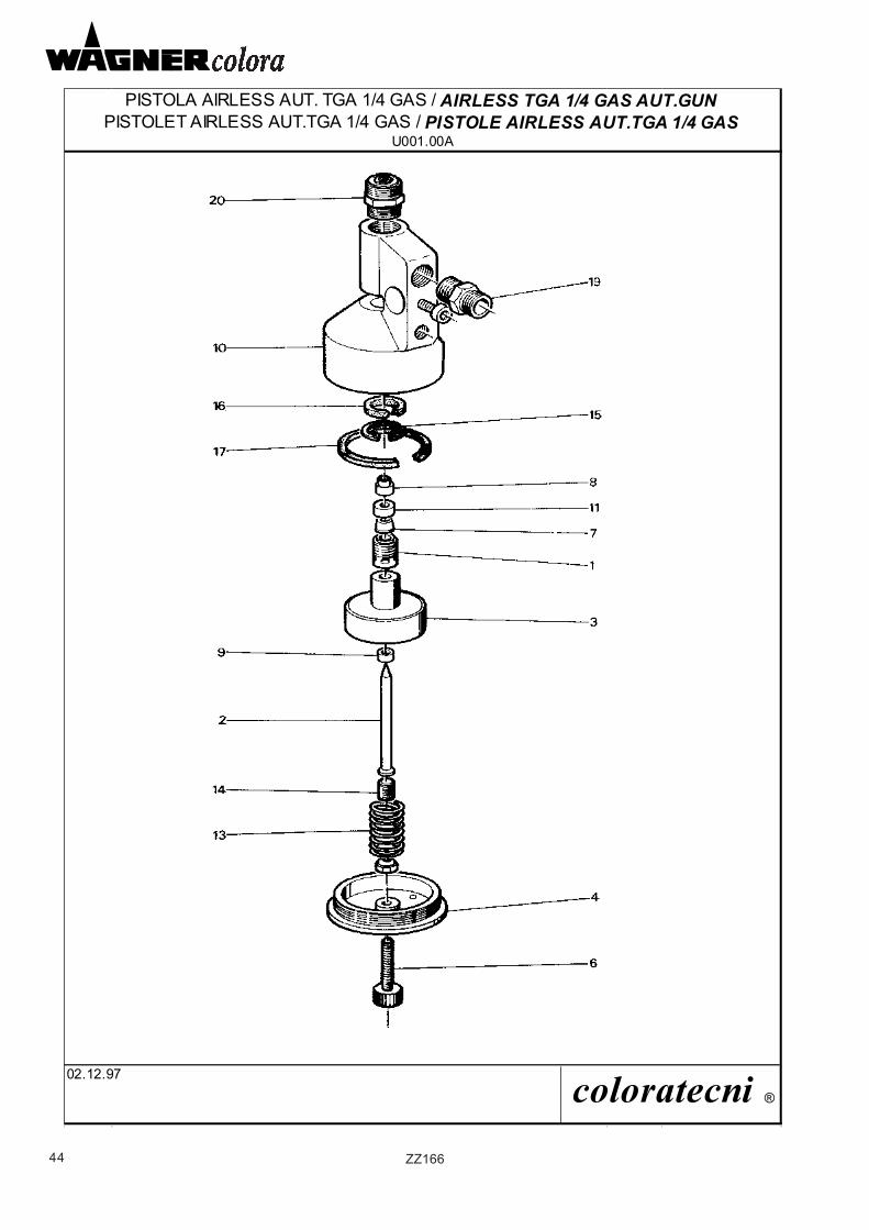
44 ZZ166
PISTOLET AIRLESS AUT.TGA 1/4 GAS / PISTOLE AIRLESS AUT.TGA 1/4 GASU001.00A
02.12.97 coloratecni ®
PISTOLA AIRLESS AUT. TGA 1/4 GAS / AIRLESS TGA 1/4 GAS AUT.GUN
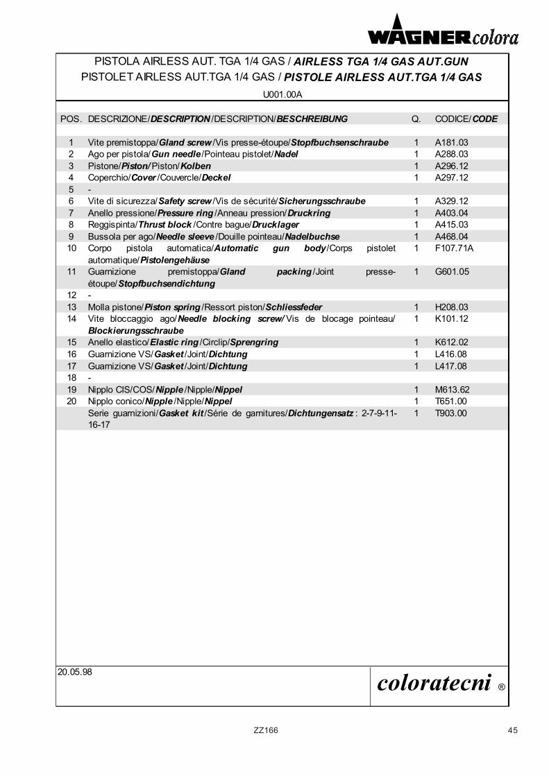
45ZZ166
PISTOLA AIRLESS AUT. TGA 1/4 GAS / AIRLESS TGA 1/4 GAS AUT.GUNPISTOLET AIRLESS AUT.TGA 1/4 GAS / PISTOLE AIRLESS AUT.TGA 1/4 GAS
U001.00A
POS. DESCRIZIONE/DESCRIPTION /DESCRIPTION/BESCHREIBUNG Q. CODICE/CODE
1 Vite premistoppa/Gland screw /Vis presse-étoupe/Stopfbuchsenschraube 1 A181.032 Ago per pistola/Gun needle /Pointeau pistolet/Nadel 1 A288.033 Pistone/Piston/ Piston/Kolben 1 A296.124 Coperchio/Cover /Couvercle/Deckel 1 A297.125 -6 Vite di sicurezza/Safety screw /Vis de sécurité/Sicherungsschraube 1 A329.127 Anello pressione/Pressure ring /Anneau pression/Druckring 1 A403.048 Reggispinta/Thrust block /Contre bague/Drucklager 1 A415.039 Bussola per ago/Needle sleeve /Douille pointeau/Nadelbuchse 1 A468.0410 Corpo pistola automatica/Automatic gun body /Corps pistolet
automatique/Pistolengehäuse 1 F107.71A
11 Guarnizione premistoppa/Gland packing /Joint presse-étoupe/Stopfbuchsendichtung
1 G601.05
12 -13 Molla pistone/Piston spring /Ressort piston/Schliessfeder 1 H208.0314 Vite bloccaggio ago/Needle blocking screw/ Vis de blocage pointeau/
Blockierungsschraube1 K101.12
15 Anello elastico/Elastic ring /Circlip/Sprengring 1 K612.0216 Guarnizione VS/Gasket /Joint/Dichtung 1 L416.0817 Guarnizione VS/Gasket /Joint/Dichtung 1 L417.0818 -19 Nipplo CIS/COS/Nipple /Nipple/Nippel 1 M613.6220 Nipplo conico/Nipple /Nipple/Nippel 1 T651.00
Serie guarnizioni/Gasket kit /Série de garnitures/Dichtungensatz : 2-7-9-11-16-17
1 T903.00
20.05.98 coloratecni ®
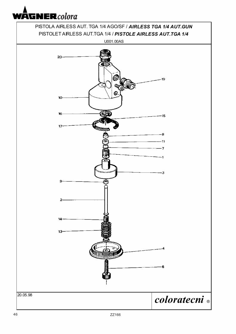
46 ZZ166
PISTOLA AIRLESS AUT. TGA 1/4 AGO/SF / AIRLESS TGA 1/4 AUT.GUN PISTOLET AIRLESS AUT.TGA 1/4 / PISTOLE AIRLESS AUT.TGA 1/4
U001.00AS
20.05.98 coloratecni ®
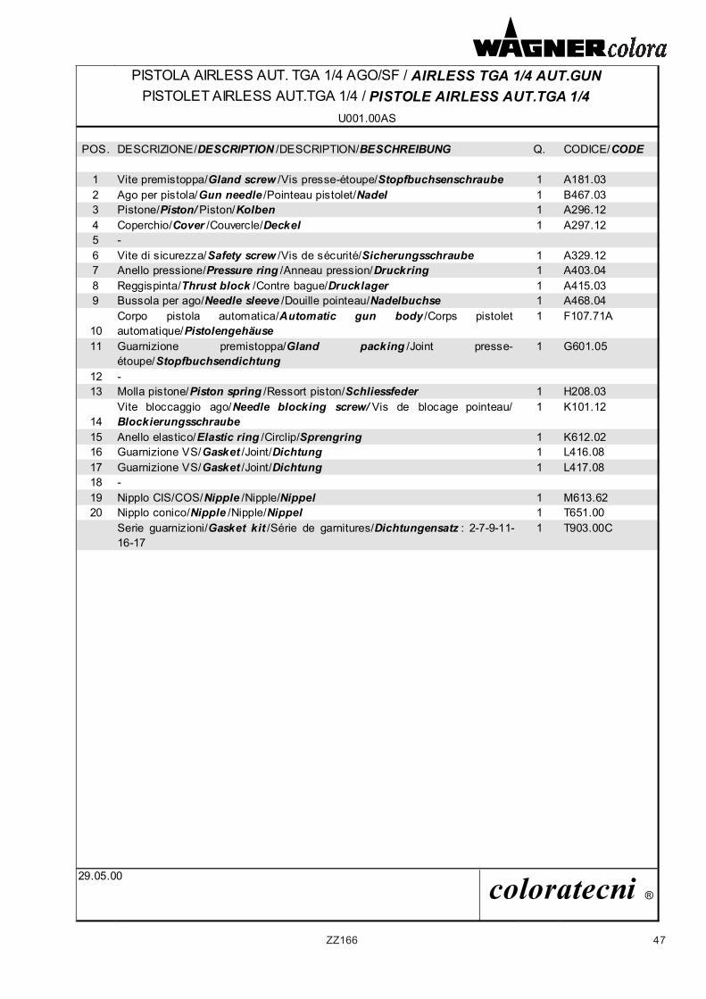
47ZZ166
PISTOLA AIRLESS AUT. TGA 1/4 AGO/SF / AIRLESS TGA 1/4 AUT.GUN PISTOLET AIRLESS AUT.TGA 1/4 / PISTOLE AIRLESS AUT.TGA 1/4
U001.00AS
POS. DESCRIZIONE/DESCRIPTION /DESCRIPTION/BESCHREIBUNG Q. CODICE/CODE
1 Vite premistoppa/Gland screw /Vis presse-étoupe/Stopfbuchsenschraube 1 A181.032 Ago per pistola/Gun needle /Pointeau pistolet/Nadel 1 B467.033 Pistone/Piston/ Piston/Kolben 1 A296.124 Coperchio/Cover /Couvercle/Deckel 1 A297.125 -6 Vite di sicurezza/Safety screw /Vis de sécurité/Sicherungsschraube 1 A329.127 Anello pressione/Pressure ring /Anneau pression/Druckring 1 A403.048 Reggispinta/Thrust block /Contre bague/Drucklager 1 A415.039 Bussola per ago/Needle sleeve /Douille pointeau/Nadelbuchse 1 A468.04
10Corpo pistola automatica/Automatic gun body /Corps pistoletautomatique/Pistolengehäuse
1 F107.71A
11 Guarnizione premistoppa/Gland packing /Joint presse-étoupe/Stopfbuchsendichtung
1 G601.05
12 -13 Molla pistone/Piston spring /Ressort piston/Schliessfeder 1 H208.03
14Vite bloccaggio ago/Needle blocking screw/ Vis de blocage pointeau/Blockierungsschraube
1 K101.12
15 Anello elastico/Elastic ring /Circlip/Sprengring 1 K612.0216 Guarnizione VS/Gasket /Joint/Dichtung 1 L416.0817 Guarnizione VS/Gasket /Joint/Dichtung 1 L417.0818 -19 Nipplo CIS/COS/Nipple /Nipple/Nippel 1 M613.6220 Nipplo conico/Nipple /Nipple/Nippel 1 T651.00
Serie guarnizioni/Gasket kit /Série de garnitures/Dichtungensatz : 2-7-9-11-16-17
1 T903.00C
29.05.00 coloratecni ®
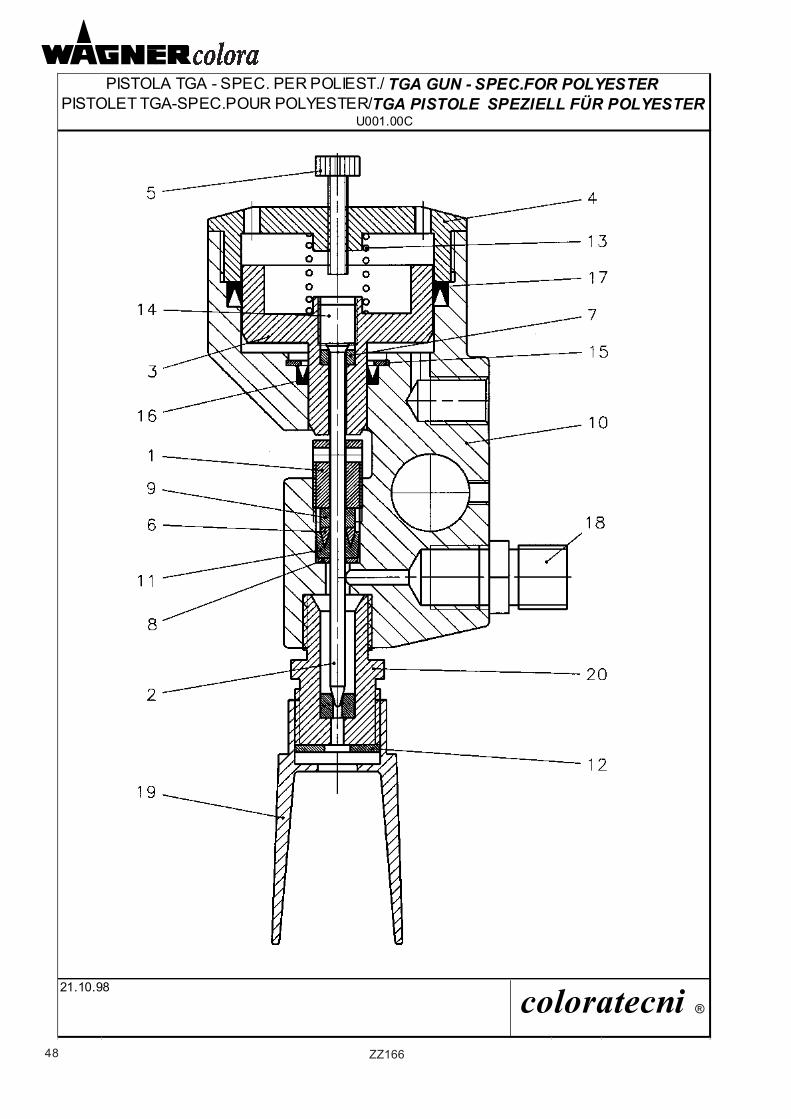
48 ZZ166
PISTOLET TGA-SPEC.POUR POLYESTER/TGA PISTOLE SPEZIELL FÜR POLYESTERU001.00C
21.10.98 coloratecni ®
PISTOLA TGA - SPEC. PER POLIEST./ TGA GUN - SPEC.FOR POLYESTER
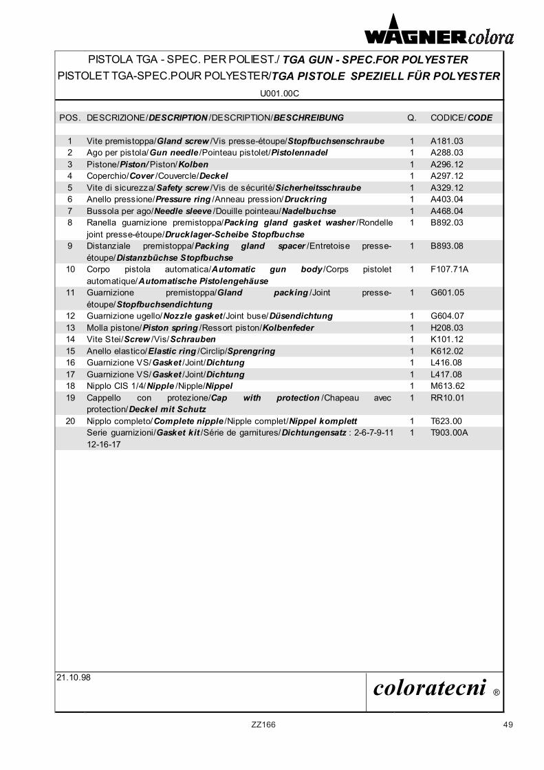
49ZZ166
PISTOLA TGA - SPEC. PER POLIEST./ TGA GUN - SPEC.FOR POLYESTER PISTOLET TGA-SPEC.POUR POLYESTER/TGA PISTOLE SPEZIELL FÜR POLYESTER
U001.00C
POS. DESCRIZIONE/DESCRIPTION /DESCRIPTION/BESCHREIBUNG Q. CODICE/CODE
1 Vite premistoppa/Gland screw /Vis presse-étoupe/Stopfbuchsenschraube 1 A181.032 Ago per pistola/Gun needle /Pointeau pistolet/Pistolennadel 1 A288.033 Pistone/Piston/ Piston/Kolben 1 A296.124 Coperchio/Cover /Couvercle/Deckel 1 A297.125 Vite di sicurezza/Safety screw /Vis de sécurité/Sicherheitsschraube 1 A329.126 Anello pressione/Pressure ring /Anneau pression/Druckring 1 A403.047 Bussola per ago/Needle sleeve /Douille pointeau/Nadelbuchse 1 A468.048 Ranella guarnizione premistoppa/Packing gland gasket washer /Rondelle
joint presse-étoupe/Drucklager-Scheibe Stopfbuchse 1 B892.03
9 Distanziale premistoppa/Packing gland spacer /Entretoise presse-étoupe/Distanzbüchse Stopfbuchse
1 B893.08
10 Corpo pistola automatica/Automatic gun body /Corps pistoletautomatique/Automatische Pistolengehäuse
1 F107.71A
11 Guarnizione premistoppa/Gland packing /Joint presse-étoupe/Stopfbuchsendichtung
1 G601.05
12 Guarnizione ugello/Nozzle gasket /Joint buse/Düsendichtung 1 G604.0713 Molla pistone/Piston spring /Ressort piston/Kolbenfeder 1 H208.0314 Vite Stei/Screw /Vis/Schrauben 1 K101.1215 Anello elastico/Elastic ring /Circlip/Sprengring 1 K612.0216 Guarnizione VS/Gasket /Joint/Dichtung 1 L416.0817 Guarnizione VS/Gasket /Joint/Dichtung 1 L417.0818 Nipplo CIS 1/4/Nipple /Nipple/Nippel 1 M613.6219 Cappello con protezione/Cap with protection /Chapeau avec
protection/Deckel mit Schutz1 RR10.01
20 Nipplo completo/Complete nipple /Nipple complet/Nippel komplett 1 T623.00Serie guarnizioni/Gasket kit /Série de garnitures/Dichtungensatz : 2-6-7-9-11-12-16-17
1 T903.00A
21.10.98 coloratecni ®
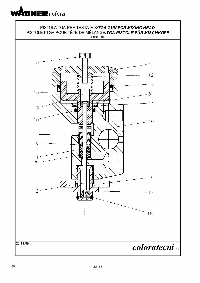
50 ZZ166
PISTOLA TGA PER TESTA MIX/TGA GUN FOR MIXING HEADPISTOLET TGA POUR TÊTE DE MÉLANGE/TGA PISTOLE FÜR MISCHKOPF
U001.00F
25.11.99 coloratecni ®
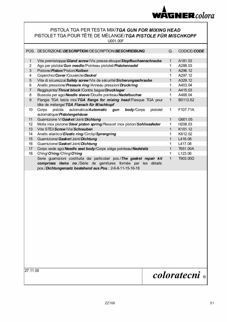
51ZZ166
PISTOLA TGA PER TESTA MIX/TGA GUN FOR MIXING HEADPISTOLET TGA POUR TÊTE DE MÉLANGE/TGA PISTOLE FÜR MISCHKOPF
U001.00F
POS. DESCRIZIONE/DESCRIPTION /DESCRIPTION/BESCHREIBUNG Q. CODICE/CODE
1 Vite premistoppa/Gland screw /Vis presse-étoupe/Stopfbuchsenschraube 1 A181.032 Ago per pistola/Gun needle /Pointeau pistolet/Pistolennadel 1 A288.033 Pistone/Piston/ Piston/Kolben 1 A296.124 Coperchio/Cover /Couvercle/Deckel 1 A297.125 Vite di sicurezza/Safety screw /Vis de sécurité/Sicherungsschraube 1 A329.126 Anello pressione/Pressure ring /Anneau pression/Druckring 1 A403.047 Reggispinta/Thrust block /Contre bague/Drucklager 1 A415.038 Bussola per ago/Needle sleeve /Douille pointeau/Nadelbuchse 1 A468.049 Flangia TGA testa mix/TGA flange for mixing head /Flasque TGA pour
tête de mélange/TGA Flansch für Mischkopf1 B0112.62
10 Corpo pistola automatica/Automatic gun body /Corps pistoletautomatique/Pistolengehäuse
1 F107.71A
11 Guarnizione V/Gasket /Joint/Dichtung 1 G601.0512 Molla inox pistone/Steel piston spring /Ressort inox piston/Sohliessfeder 1 H208.0313 Vite STEI/Screw /Vis/Schrauben 1 K101.1214 Anello elastico/Elastic ring /Circlip/Sprengring 1 K612.0215 Guarnizione/Gasket /Joint/Dichtung 1 L416.0816 Guarnizione/Gasket /Joint/Dichtung 1 L417.0817 Corpo sede ago/Needle seat body /Corps siège pointeau/Nadelsitz 1 T651.00A18 O'ring/O'ring /O'ring/O'ring 1 L123.06
Serie guarnizioni costituita dai particolari pos./The gasket repair kitcomprises items no ./Série de garnitures formée par les détailspos./Dichtungensatz bestehend aus Pos. : 2-6-8-11-15-16-18
1 T903.00D
27.11.00 coloratecni ®
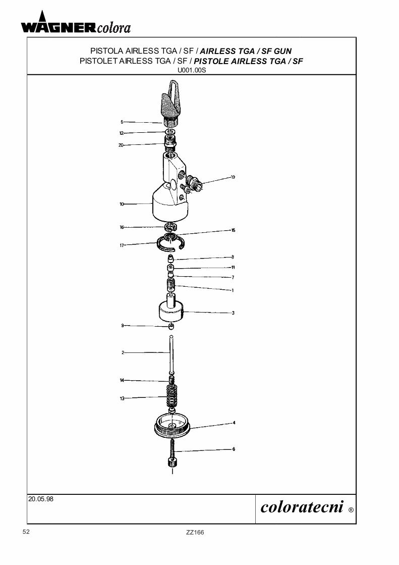
52 ZZ166
PISTOLA AIRLESS TGA / SF / AIRLESS TGA / SF GUNPISTOLET AIRLESS TGA / SF / PISTOLE AIRLESS TGA / SF
U001.00S
20.05.98 coloratecni ®
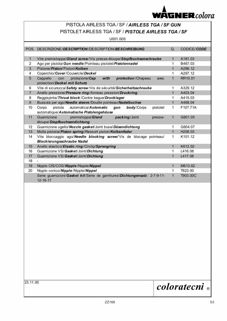
53ZZ166
PISTOLA AIRLESS TGA / SF / AIRLESS TGA / SF GUNPISTOLET AIRLESS TGA / SF / PISTOLE AIRLESS TGA / SF
U001.00S
POS. DESCRIZIONE/DESCRIPTION /DESCRIPTION/BESCHREIBUNG Q. CODICE/CODE
1 Vite premistoppa/Gland screw /Vis presse-étoupe/Stopfbuchsenschraube 1 A181.032 Ago per pistola/Gun needle /Pointeau pistolet/Pistolennadel 1 B467.033 Pistone/Piston/ Piston/Kolben 1 A296.124 Coperchio/Cover /Couvercle/Deckel 1 A297.125 Cappello con protezione/Cap with protection /Chapeau avec
protection/Deckel mit Schutz1 RR10.01
6 Vite di sicurezza/Safety screw /Vis de sécurité/Sicherheitsschraube 1 A329.127 Anello pressione/Pressure ring /Anneau pression/Druckring 1 A403.048 Reggispinta/Thrust block /Contre bague/Drucklager 1 A415.039 Bussola per ago/Needle sleeve /Douille pointeau/Nadelbuchse 1 A468.0410 Corpo pistola automatica/Automatic gun body /Corps pistolet
automatique/Automatische Pistolengehäuse1 F107.71A
11 Guarnizione premistoppa/Gland packing /Joint presse-étoupe/Stopfbuchsendichtung
1 G601.05
12 Guarnizione ugello/Nozzle gasket /Joint buse/Düsendichtung 1 G604.0713 Molla pistone/Piston spring /Ressort piston/Kolbenfeder 1 H208.0314 Vite bloccaggio ago/Needle blocking screw/ Vis de blocage pointeau/
Blockierungsschraube Nadel1 K101.12
15 Anello elastico/Elastic ring /Circlip/Sprengring 1 K612.0216 Guarnizione VS/Gasket /Joint/Dichtung 1 L416.0817 Guarnizione VS/Gasket /Joint/Dichtung 1 L417.0818 -19 Nipplo CIS/COS/Nipple /Nipple/Nippel 1 M613.6220 Nipplo conico/Nipple /Nipple/Nippel 1 T623.00
Serie guarnizioni/Gasket kit /Série de garnitures/Dichtungensatz : 2-7-9-11-12-16-17
1 T903.00C
23.11.00 coloratecni ®
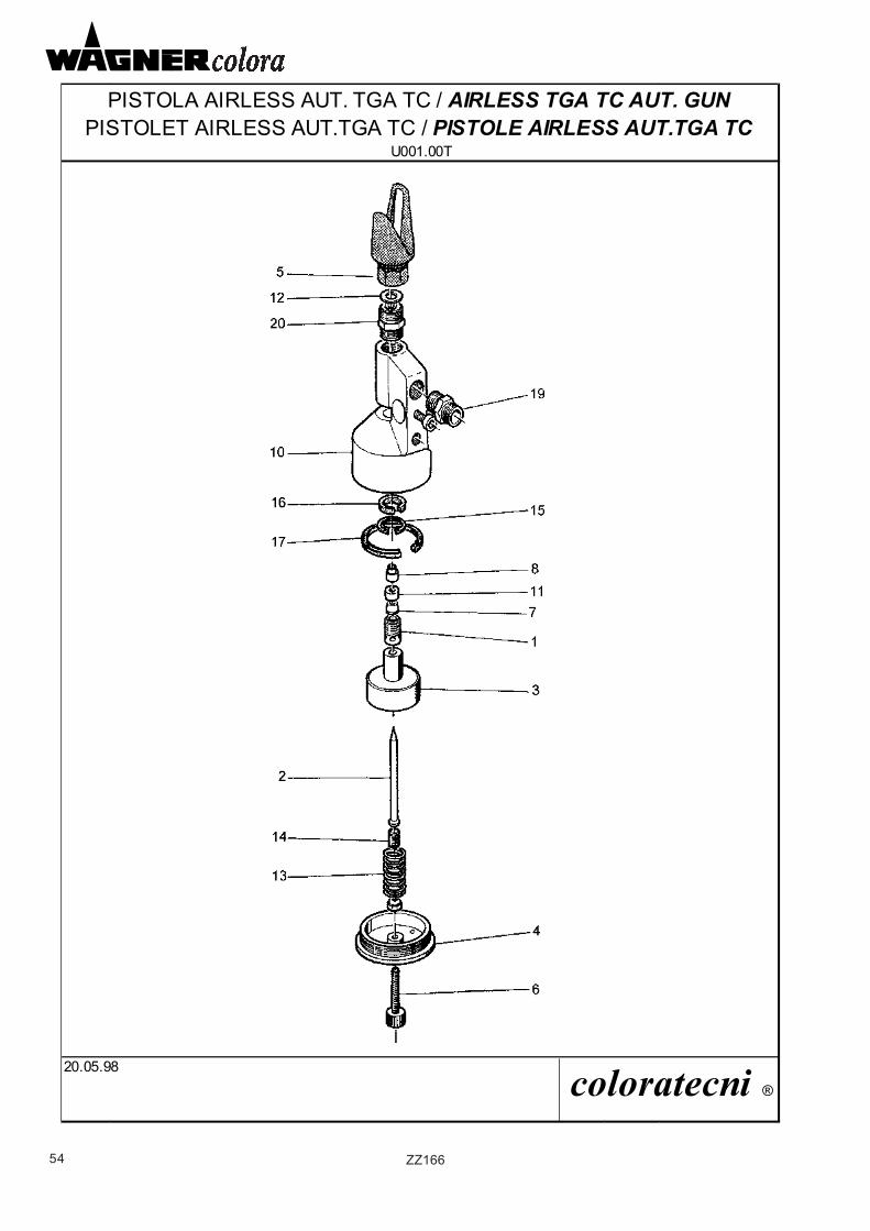
54 ZZ166
PISTOLA AIRLESS AUT. TGA TC / AIRLESS TGA TC AUT. GUNPISTOLET AIRLESS AUT.TGA TC / PISTOLE AIRLESS AUT.TGA TC
U001.00T
20.05.98 coloratecni ®
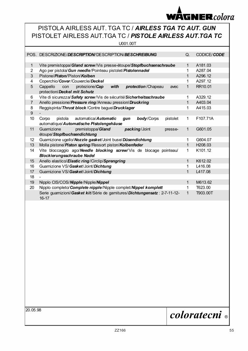
55ZZ166
PISTOLA AIRLESS AUT. TGA TC / AIRLESS TGA TC AUT. GUNPISTOLET AIRLESS AUT.TGA TC / PISTOLE AIRLESS AUT.TGA TC
U001.00T
POS. DESCRIZIONE/DESCRIPTION/ DESCRIPTION/BESCHREIBUNG Q. CODICE/CODE
1 Vite premistoppa/Gland screw /Vis presse-étoupe/Stopfbuchsenschraube 1 A181.032 Ago per pistola/Gun needle /Pointeau pistolet/Pistolennadel 1 A287.043 Pistone/Piston/ Piston/Kolben 1 A296.124 Coperchio/Cover /Couvercle/Deckel 1 A297.125 Cappello con protezione/Cap with protection /Chapeau avec
protection/Deckel mit Schutz1 RR10.01
6 Vite di sicurezza/Safety screw /Vis de sécurité/Sicherheitsschraube 1 A329.127 Anello pressione/Pressure ring /Anneau pression/Druckring 1 A403.048 Reggispinta/Thrust block /Contre bague/Drucklager 1 A415.039 -10 Corpo pistola automatica/Automatic gun body /Corps pistolet
automatique/Automatische Pistolengehäuse 1 F107.71A
11 Guarnizione premistoppa/Gland packing /Joint presse-étoupe/Stopfbuchsendichtung
1 G601.05
12 Guarnizione ugello/Nozzle gasket/Joint buse/Düsendichtung 1 G604.0713 Molla pistone/Piston spring /Ressort piston/Kolbenfeder 1 H208.0314 Vite bloccaggio ago/Needle blocking screw/ Vis de blocage pointeau/
Blockierungsschraube Nadel1 K101.12
15 Anello elastico/Elastic ring /Circlip/Sprengring 1 K612.0216 Guarnizione VS/Gasket /Joint/Dichtung 1 L416.0817 Guarnizione VS/Gasket /Joint/Dichtung 1 L417.0818 -19 Nipplo CIS/COS/Nipple /Nipple/Nippel 1 M613.6220 Nipplo completo/Complete nipple /Nipple complet/Nippel komplett 1 T623.00
Serie guarnizioni/Gasket kit /Série de garnitures/Dichtungensatz : 2-7-11-12-16-17
1 T903.00T
20.05.98 coloratecni ®
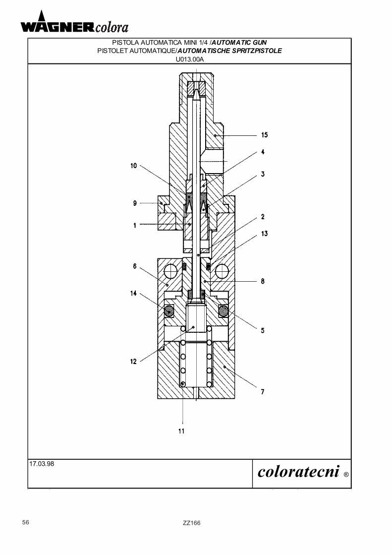
56 ZZ166
PISTOLA AUTOMATICA MINI 1/4 /AUTOMATIC GUNPISTOLET AUTOMATIQUE/AUTOMATISCHE SPRITZPISTOLE
U013.00A
17.03.98 coloratecni ®
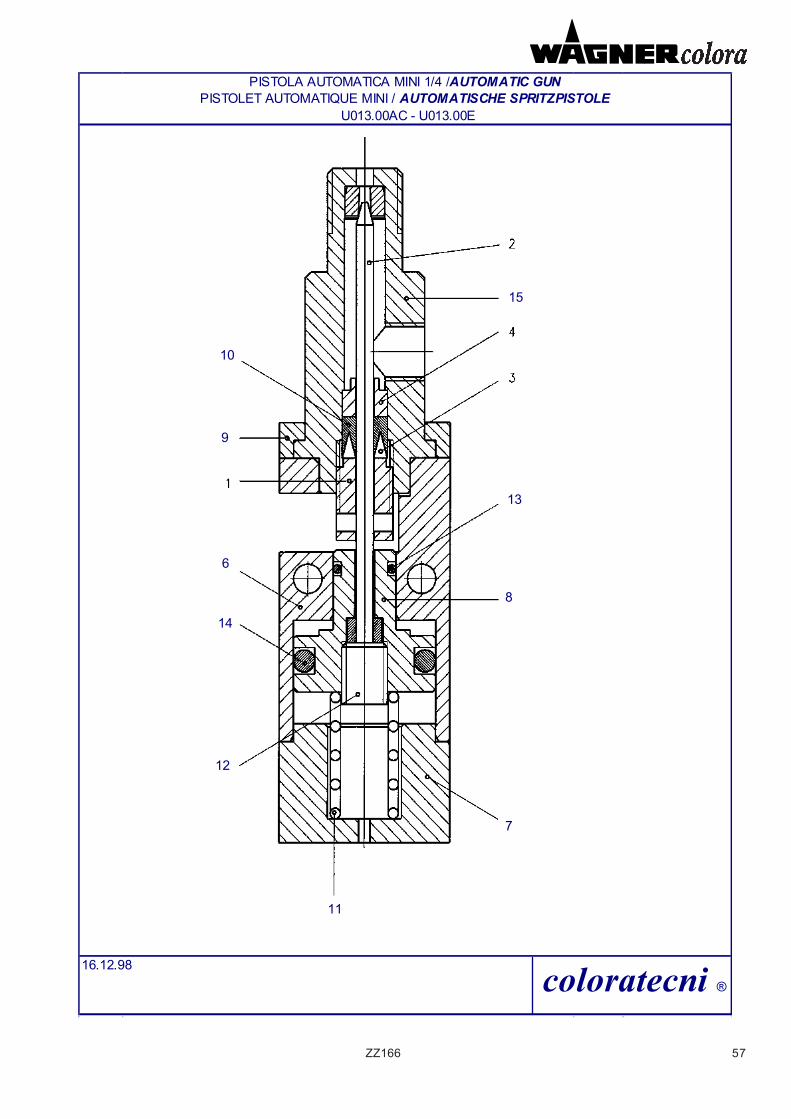
57ZZ166
PISTOLET AUTOMATIQUE MINI / AUTOMATISCHE SPRITZPISTOLE U013.00AC - U013.00E
16.12.98 coloratecni ®
PISTOLA AUTOMATICA MINI 1/4 /AUTOMATIC GUN
15
10
9
13
8
7
11
12
14
6
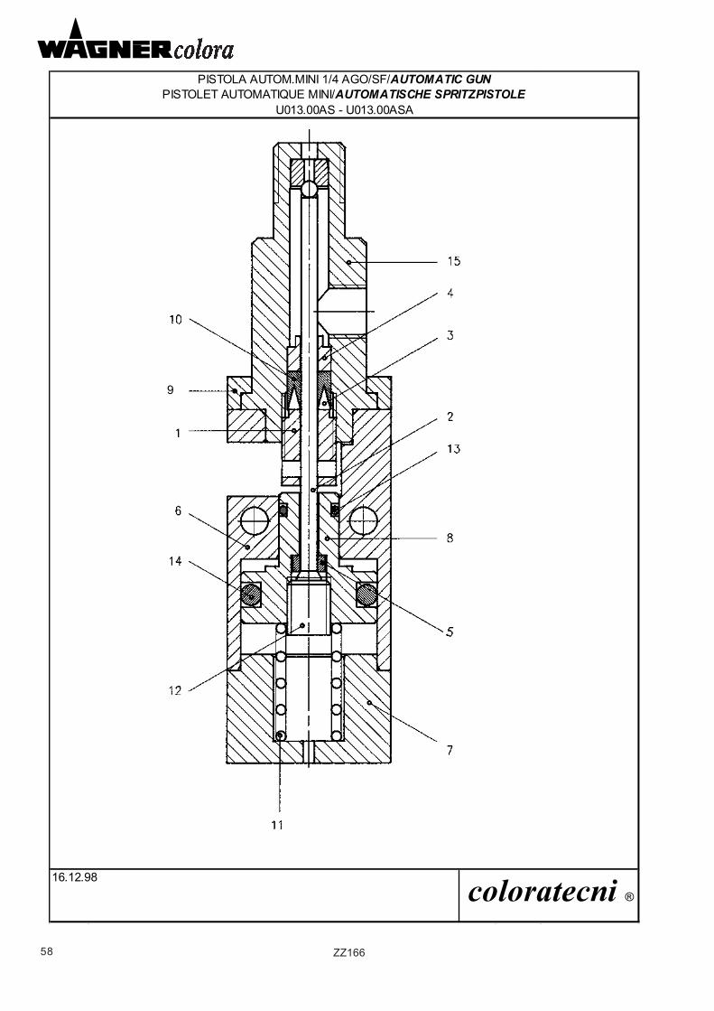
58 ZZ166
PISTOLA AUTOM.MINI 1/4 AGO/SF/AUTOMATIC GUNPISTOLET AUTOMATIQUE MINI/AUTOMATISCHE SPRITZPISTOLE
U013.00AS - U013.00ASA
16.12.98 coloratecni ®
9
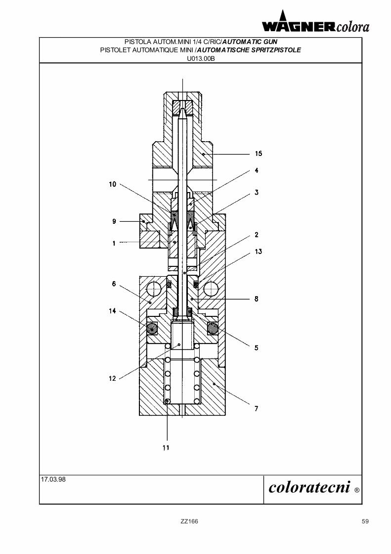
59ZZ166
PISTOLA AUTOM.MINI 1/4 C/RIC/AUTOMATIC GUNPISTOLET AUTOMATIQUE MINI /AUTOMATISCHE SPRITZPISTOLE
U013.00B
17.03.98 coloratecni ®
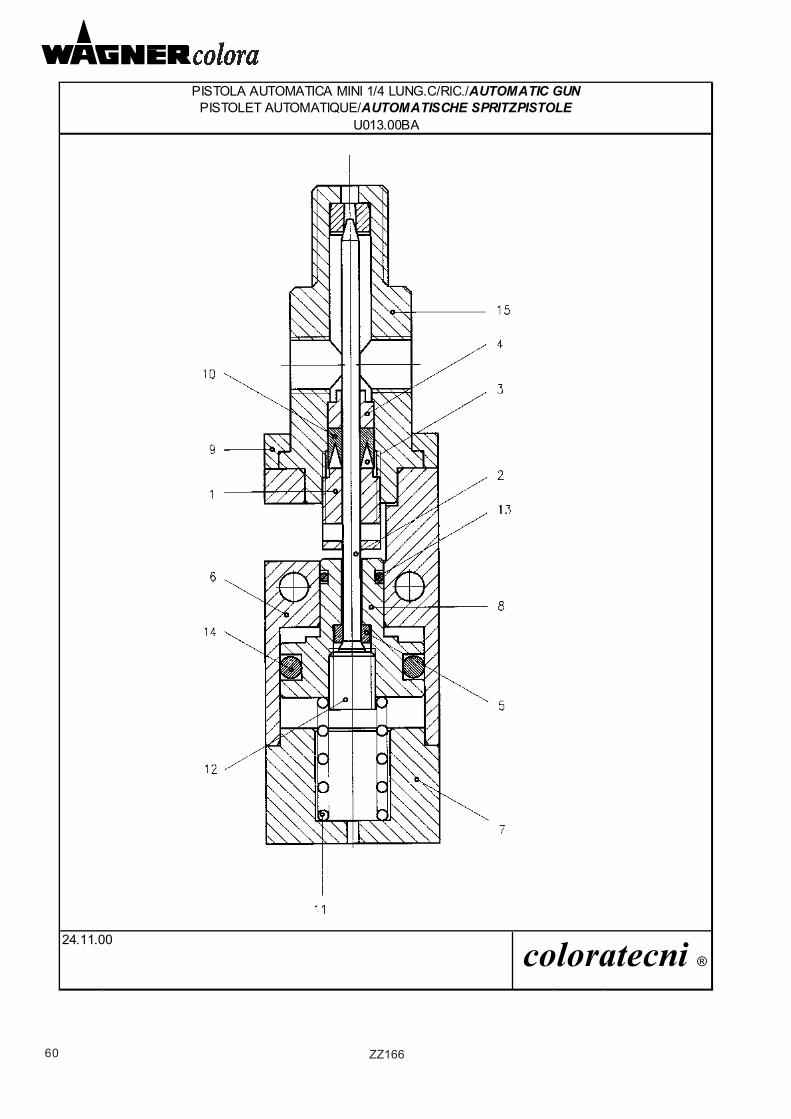
60 ZZ166
PISTOLA AUTOMATICA MINI 1/4 LUNG.C/RIC./AUTOMATIC GUNPISTOLET AUTOMATIQUE/AUTOMATISCHE SPRITZPISTOLE
U013.00BA
24.11.00 coloratecni ®
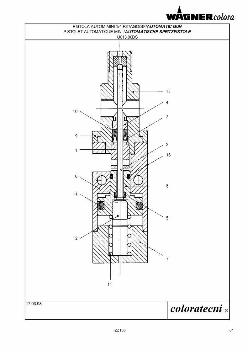
61ZZ166
PISTOLA AUTOM.MINI 1/4 RIT/AGO/SF/AUTOMATIC GUNPISTOLET AUTOMATIQUE MINI /AUTOMATISCHE SPRITZPISTOLE
U013.00BS
17.03.98 coloratecni ®
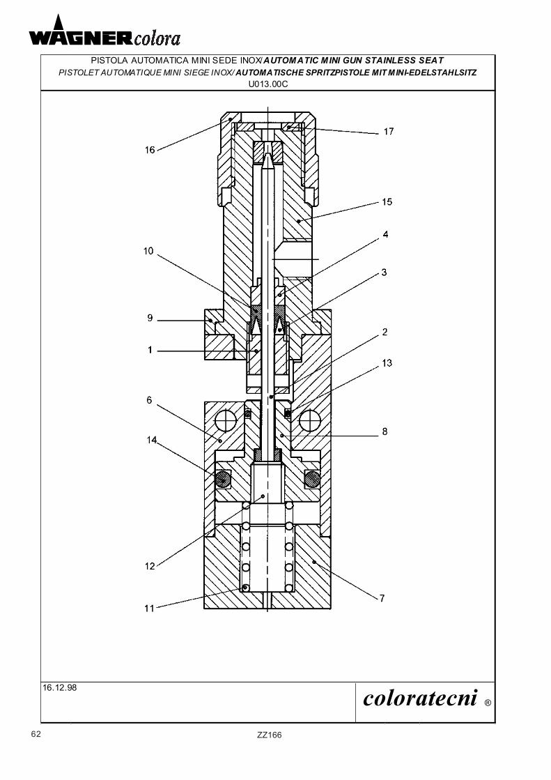
62 ZZ166
PISTOLA AUTOMATICA MINI SEDE INOX/AUTOMATIC MINI GUN STAINLESS SEATPISTOLET AUTOMATIQUE MINI SIEGE INOX/ AUTOMATISCHE SPRITZPISTOLE MIT MINI-EDELSTAHLSITZ
U013.00C
16.12.98 coloratecni ®
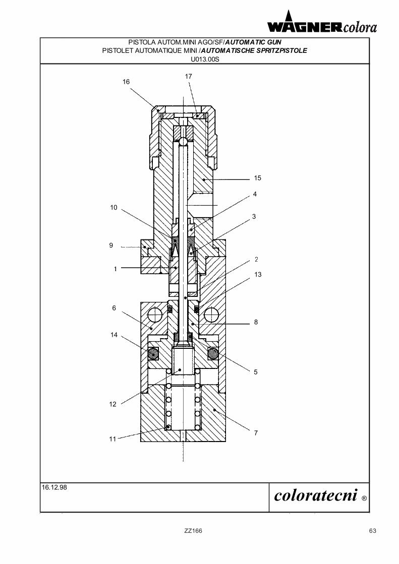
63ZZ166
PISTOLA AUTOM.MINI AGO/SF/AUTOMATIC GUNPISTOLET AUTOMATIQUE MINI /AUTOMATISCHE SPRITZPISTOLE
U013.00S
16.12.98 coloratecni ®
1617
15
4
310
9
13
8
6
14
5
711
12
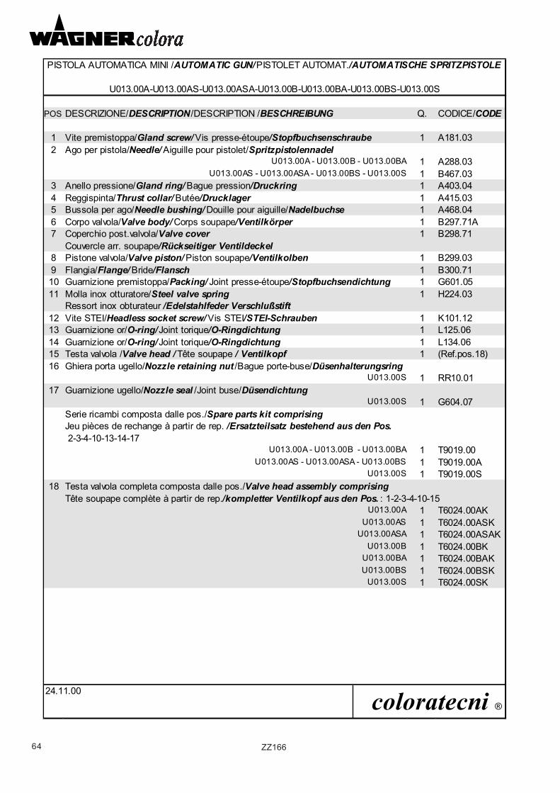
64 ZZ166
PISTOLA AUTOMATICA MINI /AUTOMATIC GUN/PISTOLET AUTOMAT./AUTOMATISCHE SPRITZPISTOLE
POS.DESCRIZIONE/DESCRIPTION/DESCRIPTION /BESCHREIBUNG Q. CODICE/CODE
1 Vite premistoppa/Gland screw/ Vis presse-étoupe/Stopfbuchsenschraube 1 A181.032 Ago per pistola/Needle/ Aiguille pour pistolet/Spritzpistolennadel
U013.00A - U013.00B - U013.00BA 1 A288.03U013.00AS - U013.00ASA - U013.00BS - U013.00S 1 B467.03
3 Anello pressione/Gland ring/ Bague pression/Druckring 1 A403.044 Reggispinta/Thrust collar/ Butée/Drucklager 1 A415.035 Bussola per ago/Needle bushing/ Douille pour aiguille/Nadelbuchse 1 A468.046 Corpo valvola/Valve body/ Corps soupape/Ventilkörper 1 B297.71A7 Coperchio post.valvola/Valve cover 1 B298.71
Couvercle arr. soupape/Rückseitiger Ventildeckel8 Pistone valvola/Valve piston/ Piston soupape/Ventilkolben 1 B299.039 Flangia/Flange/ Bride/Flansch 1 B300.7110 Guarnizione premistoppa/Packing/ Joint presse-étoupe/Stopfbuchsendichtung 1 G601.0511 Molla inox otturatore/Steel valve spring 1 H224.03
Ressort inox obturateur /Edelstahlfeder Verschlußstift 12 Vite STEI/Headless socket screw/ Vis STEI/STEI-Schrauben 1 K101.1213 Guarnizione or/O-ring/Joint torique/O-Ringdichtung 1 L125.0614 Guarnizione or/O-ring/Joint torique/O-Ringdichtung 1 L134.0615 Testa valvola /Valve head / Tête soupape / Ventilkopf 1 (Ref.pos.18)16 Ghiera porta ugello/Nozzle retaining nut /Bague porte-buse/Düsenhalterungsring
U013.00S 1 RR10.0117 Guarnizione ugello/Nozzle seal /Joint buse/Düsendichtung
U013.00S 1 G604.07Serie ricambi composta dalle pos./Spare parts kit comprisingJeu pièces de rechange à partir de rep. /Ersatzteilsatz bestehend aus den Pos. 2-3-4-10-13-14-17
U013.00A - U013.00B - U013.00BA 1 T9019.00U013.00AS - U013.00ASA - U013.00BS 1 T9019.00A
U013.00S 1 T9019.00S18 Testa valvola completa composta dalle pos./Valve head assembly comprising
Tête soupape complète à partir de rep./kompletter Ventilkopf aus den Pos. : 1-2-3-4-10-15U013.00A 1 T6024.00AK
U013.00AS 1 T6024.00ASKU013.00ASA 1 T6024.00ASAK
U013.00B 1 T6024.00BKU013.00BA 1 T6024.00BAKU013.00BS 1 T6024.00BSK
U013.00S 1 T6024.00SK
24.11.00 coloratecni ®
U013.00A-U013.00AS-U013.00ASA-U013.00B-U013.00BA-U013.00BS-U013.00S
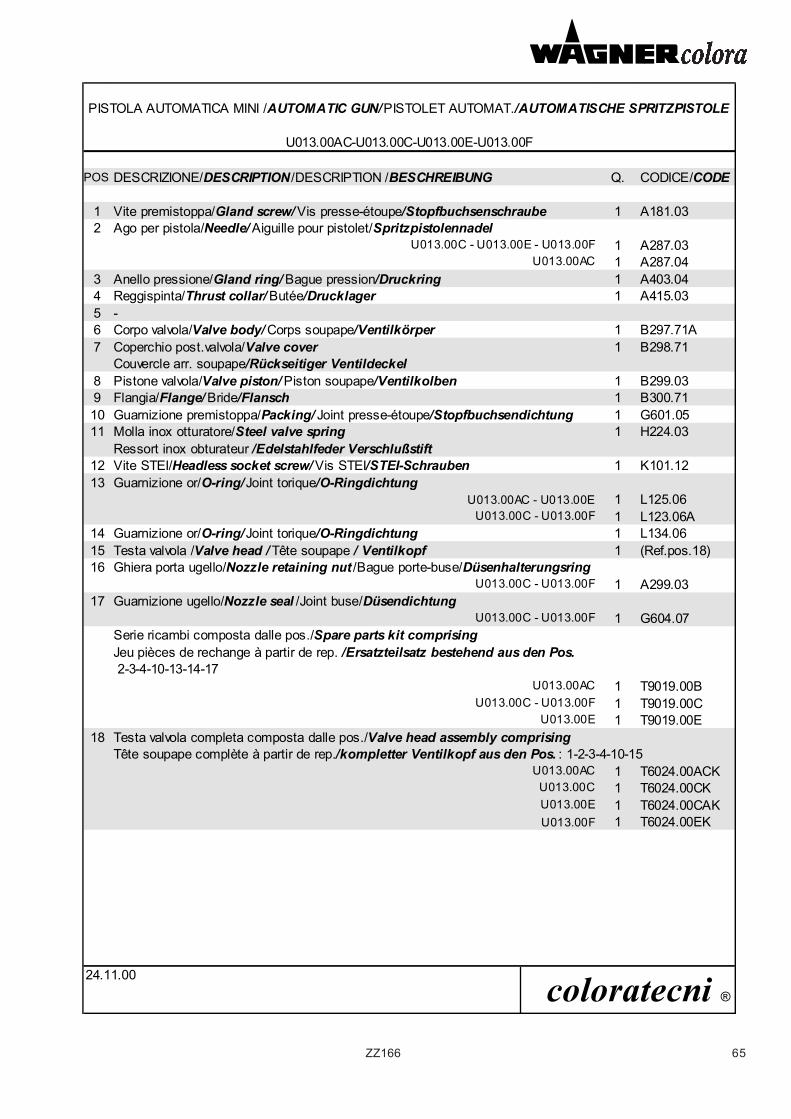
65ZZ166
PISTOLA AUTOMATICA MINI /AUTOMATIC GUN/PISTOLET AUTOMAT./AUTOMATISCHE SPRITZPISTOLE
POS.DESCRIZIONE/DESCRIPTION/DESCRIPTION /BESCHREIBUNG Q. CODICE/CODE
1 Vite premistoppa/Gland screw/ Vis presse-étoupe/Stopfbuchsenschraube 1 A181.032 Ago per pistola/Needle/ Aiguille pour pistolet/Spritzpistolennadel
U013.00C - U013.00E - U013.00F 1 A287.03U013.00AC 1 A287.04
3 Anello pressione/Gland ring/ Bague pression/Druckring 1 A403.044 Reggispinta/Thrust collar/ Butée/Drucklager 1 A415.035 -6 Corpo valvola/Valve body/ Corps soupape/Ventilkörper 1 B297.71A7 Coperchio post.valvola/Valve cover 1 B298.71
Couvercle arr. soupape/Rückseitiger Ventildeckel8 Pistone valvola/Valve piston/ Piston soupape/Ventilkolben 1 B299.039 Flangia/Flange/ Bride/Flansch 1 B300.7110 Guarnizione premistoppa/Packing/ Joint presse-étoupe/Stopfbuchsendichtung 1 G601.0511 Molla inox otturatore/Steel valve spring 1 H224.03
Ressort inox obturateur /Edelstahlfeder Verschlußstift 12 Vite STEI/Headless socket screw/ Vis STEI/STEI-Schrauben 1 K101.1213 Guarnizione or/O-ring/Joint torique/O-Ringdichtung
U013.00AC - U013.00E 1 L125.06U013.00C - U013.00F 1 L123.06A
14 Guarnizione or/O-ring/Joint torique/O-Ringdichtung 1 L134.0615 Testa valvola /Valve head / Tête soupape / Ventilkopf 1 (Ref.pos.18)16 Ghiera porta ugello/Nozzle retaining nut /Bague porte-buse/Düsenhalterungsring
U013.00C - U013.00F 1 A299.0317 Guarnizione ugello/Nozzle seal /Joint buse/Düsendichtung
U013.00C - U013.00F 1 G604.07Serie ricambi composta dalle pos./Spare parts kit comprisingJeu pièces de rechange à partir de rep. /Ersatzteilsatz bestehend aus den Pos. 2-3-4-10-13-14-17
U013.00AC 1 T9019.00BU013.00C - U013.00F 1 T9019.00C
U013.00E 1 T9019.00E18 Testa valvola completa composta dalle pos./Valve head assembly comprising
Tête soupape complète à partir de rep./kompletter Ventilkopf aus den Pos. : 1-2-3-4-10-15U013.00AC 1 T6024.00ACKU013.00C 1 T6024.00CKU013.00E 1 T6024.00CAKU013.00F 1 T6024.00EK
24.11.00 coloratecni ®
U013.00AC-U013.00C-U013.00E-U013.00F
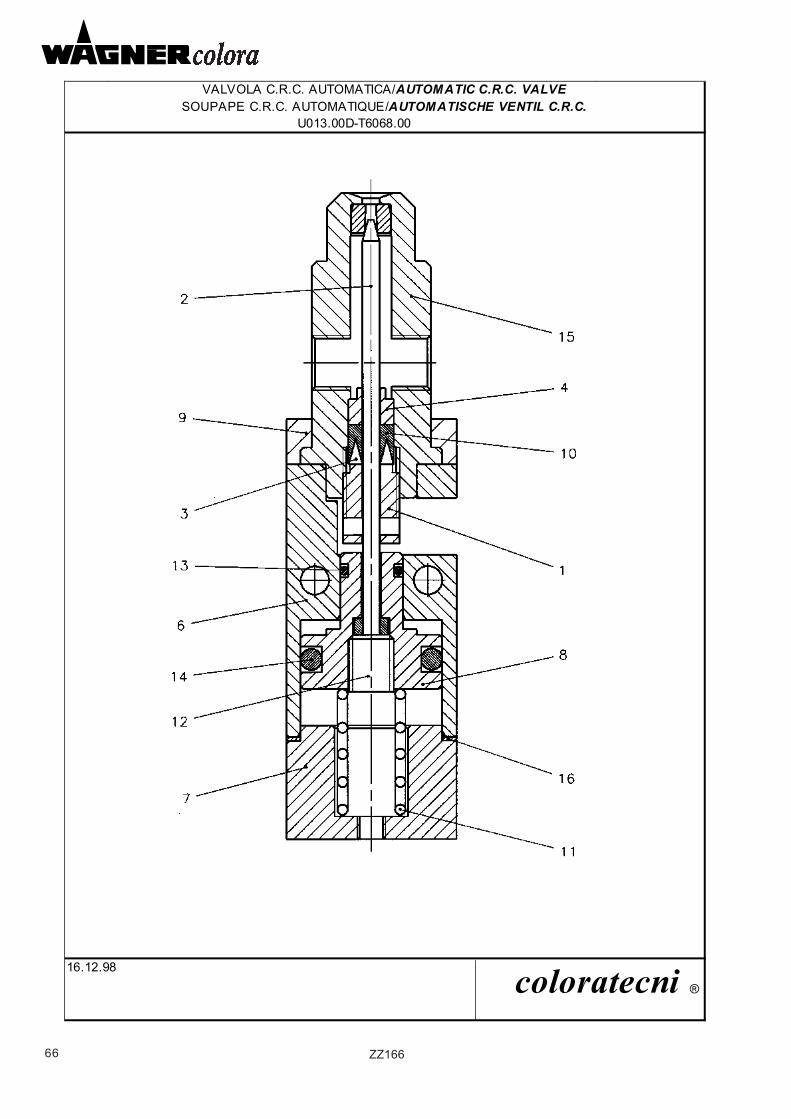
66 ZZ166
VALVOLA C.R.C. AUTOMATICA/AUTOMATIC C.R.C. VALVESOUPAPE C.R.C. AUTOMATIQUE/AUTOMATISCHE VENTIL C.R.C.
U013.00D-T6068.00
16.12.98 coloratecni ®
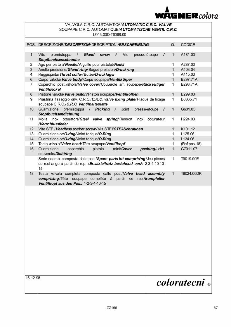
67ZZ166
VALVOLA C.R.C. AUTOMATICA/AUTOMATIC C.R.C. VALVESOUPAPE C.R.C. AUTOMATIQUE/AUTOMATISCHE VENTIL C.R.C.
U013.00D-T6068.00
POS. DESCRIZIONE/DESCRIPTION/ DESCRIPTION /BESCHREIBUNG Q. CODICE
1 Vite premistoppa / Gland screw / Vis presse-étoupe / Stopfbuchsenschraube
1 A181.03
2 Ago per pistola/Needle/ Aiguille pour pistolet/Nadel 1 A287.033 Anello pressione/Gland ring/ Bague pression/Druckring 1 A403.044 Reggispinta/Thrust collar/ Butée/Drucklager 1 A415.036 Corpo valvola/Valve body/ Corps soupape/Ventilkörper 1 B297.71A7 Coperchio post.valvola/Valve cover/ Couvercle arr. soupape/Rückseitiger
Ventildeckel1 B298.71A
8 Pistone valvola/Valve piston/Piston soupape/Ventilkolben 1 B299.039 Piastrina fissaggio valv. C.R.C./C.R.C. valve fixing plate/ Plaque de fixage
soupape C.R.C./C.R.C. Ventilhalteplatte 1 B0065.71
10 Guarnizione premistoppa / Packing / Joint presse-étoupe / Stopfbuchsendichtung
1 G601.05
11 Molla inox otturatore/Steel valve spring/ Ressort inox obturateur/Verschlussfeder
1 H224.03
12 Vite STEI/Headless socket screw / Vis STEI/STEI-Schrauben 1 K101.1213 Guarnizione or/O-ring/ Joint torique/O-Ring 1 L125.0614 Guarnizione or/O-ring/ Joint torique/O-Ring 1 L134.0615 Testa valvola/Valve head/ Tête soupape/Ventilkopf 1 (Ref.pos.18)16 Guarnizione coperchio pistola mini/Cover packing /Joint
couvercle/Dichtring1 G7011.07
Serie ricambi composta dalle pos./Spare parts kit comprising /Jeu pièces de rechange à partir de rep. /Ersatzteilsatz bestehend ausi: 2-3-4-10-13-14
1 T9019.00E
18 Testa valvola completa composta dalle pos./Valve head assemblycomprising /Tête soupape complète à partir de rep./kompletter Ventilkopf aus den Pos.: 1-2-3-4-10-15
1 T6024.00DK
16.12.98 coloratecni ®
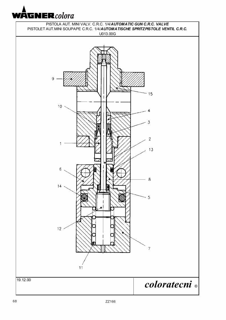
68 ZZ166
PISTOLA AUT. MINI VALV. C.R.C. 1/4/AUTOMATIC GUN C.R.C. VALVEPISTOLET AUT.MINI SOUPAPE C.R.C. 1/4/AUTOMATISCHE SPRITZPISTOLE VENTIL C.R.C.
19.12.00 coloratecni ®
U013.00G
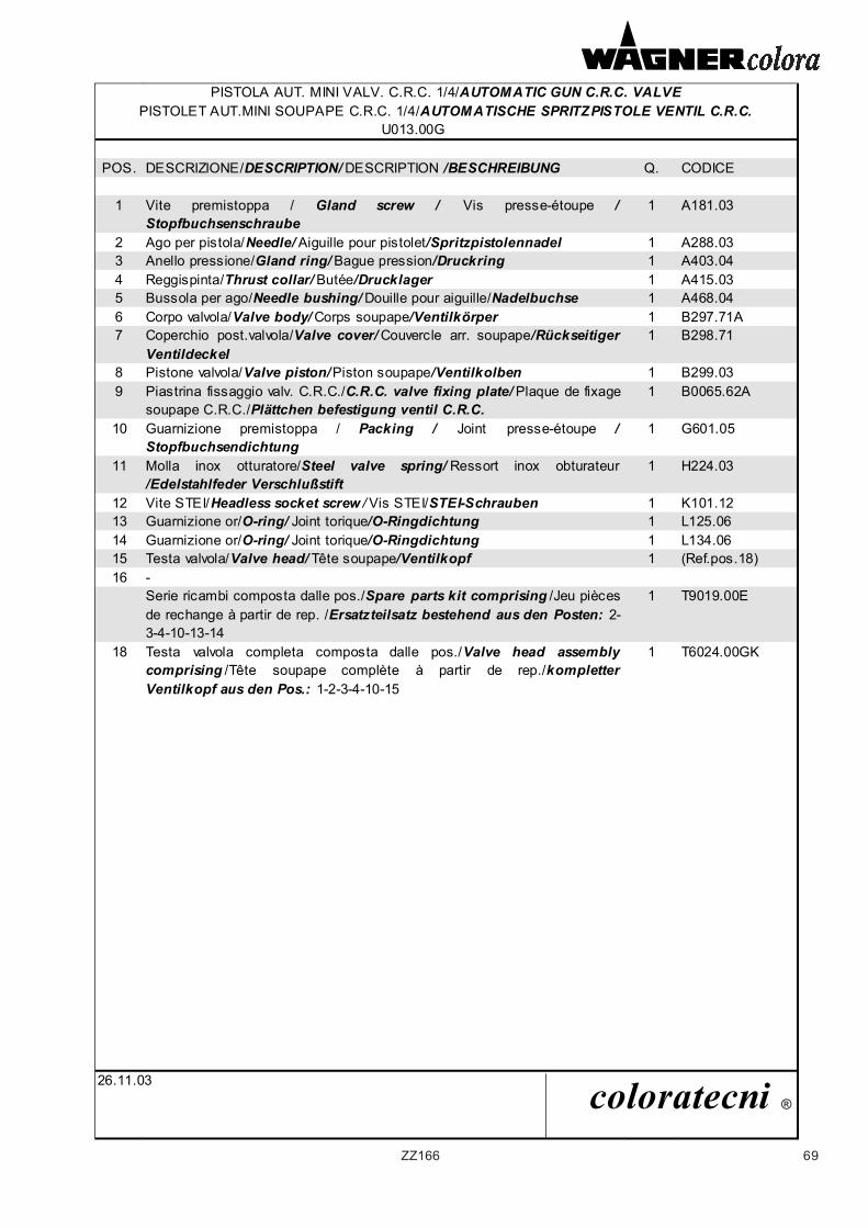
69ZZ166
PISTOLA AUT. MINI VALV. C.R.C. 1/4/AUTOMATIC GUN C.R.C. VALVEPISTOLET AUT.MINI SOUPAPE C.R.C. 1/4/AUTOMATISCHE SPRITZPISTOLE VENTIL C.R.C.
U013.00G
POS. DESCRIZIONE/DESCRIPTION/ DESCRIPTION /BESCHREIBUNG Q. CODICE
1 Vite premistoppa / Gland screw / Vis presse-étoupe / Stopfbuchsenschraube
1 A181.03
2 Ago per pistola/Needle/ Aiguille pour pistolet/Spritzpistolennadel 1 A288.033 Anello pressione/Gland ring/ Bague pression/Druckring 1 A403.044 Reggispinta/Thrust collar/ Butée/Drucklager 1 A415.035 Bussola per ago/Needle bushing/ Douille pour aiguille/Nadelbuchse 1 A468.046 Corpo valvola/Valve body/ Corps soupape/Ventilkörper 1 B297.71A7 Coperchio post.valvola/Valve cover/ Couvercle arr. soupape/Rückseitiger
Ventildeckel1 B298.71
8 Pistone valvola/Valve piston/ Piston soupape/Ventilkolben 1 B299.039 Piastrina fissaggio valv. C.R.C./C.R.C. valve fixing plate/ Plaque de fixage
soupape C.R.C./Plättchen befestigung ventil C.R.C.1 B0065.62A
10 Guarnizione premistoppa / Packing / Joint presse-étoupe / Stopfbuchsendichtung
1 G601.05
11 Molla inox otturatore/Steel valve spring/ Ressort inox obturateur/Edelstahlfeder Verschlußstift
1 H224.03
12 Vite STEI/Headless socket screw / Vis STEI/STEI-Schrauben 1 K101.1213 Guarnizione or/O-ring/ Joint torique/O-Ringdichtung 1 L125.0614 Guarnizione or/O-ring/ Joint torique/O-Ringdichtung 1 L134.0615 Testa valvola/Valve head/ Tête soupape/Ventilkopf 1 (Ref.pos.18)16 -
Serie ricambi composta dalle pos./Spare parts kit comprising /Jeu pièces de rechange à partir de rep. /Ersatzteilsatz bestehend aus den Posten: 2-3-4-10-13-14
1 T9019.00E
18 Testa valvola completa composta dalle pos./Valve head assemblycomprising /Tête soupape complète à partir de rep./kompletter Ventilkopf aus den Pos.: 1-2-3-4-10-15
1 T6024.00GK
26.11.03 coloratecni ®
70 ZZ166
TIMBRO DEL CONCESSIONARIO
DEALER'S STAMP
TAMPON DU CONCESSIONNAIRE
STEMPEL IHRES HÄNDLERS
![Engine MINI-10 - Solé Diesel · 19 13722058 4 Retainer Valve SP 20 13222059 8 Lock Valve [NP] Not provided. 3118. 5. D_MI09_1_4. Engine MINI-10. Engine Body. Cranckcase. FIG. REF](https://img.pdfslide.us/doc/110x75/602cc50b4904b050bd02f771/engine-mini-10-sol-19-13722058-4-retainer-valve-sp-20-13222059-8-lock-valve.jpg)