Embed Size (px)
Citation preview
INSTRUCTION MANUAL MODEL 1200
ATMOSPHERIC CONSISTOMETER
Revision L – November 2015 P/N: 12-0185
S/N: ____________
2001 N. Indianwood Ave Broken Arrow, Oklahoma 74012 U.S.A.
Telephone: 918-250-7200 Fax: 918-459-0165
E-mail: [email protected] Website: http://www.chandlereng.com

Copyright © 2015, by Chandler Engineering Company, LLC P.O. Box 470710 Tulsa, Oklahoma 74147 All rights reserved. Reproduction or use of contents in any manner is prohibited without express permission from Chandler Engineering Company, LLC. While every precaution has been taken in the preparation of this manual, the publisher assumes no responsibility for errors or omissions. Neither is any liability assumed for damages resulting from the use of the information contained herein.
This publication contains the following trademarks and/or registered trademarks: AMETEK, CHANDLER ENGINEERING. These trademarks or registered trademarks and stylized logos are all owned by AMETEK, Inc. All other company, product and service names and logos are trademarks or service marks of their respective owners.
TABLE OF CONTENTS T-1
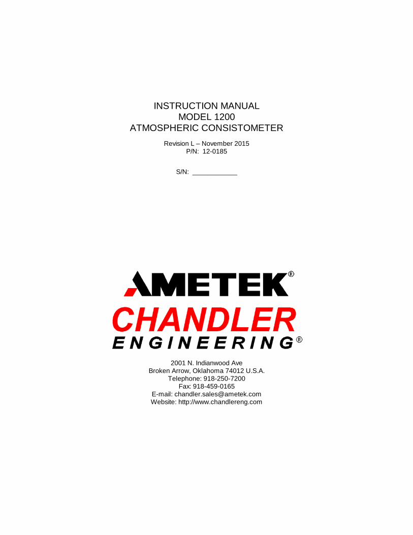
Table of Contents General Information................................................................ P-1
Introduction ...................................................................................................................... P-1 Purpose and Use .......................................................................................................... P-1 Description .................................................................................................................. P-1
Features and Benefits ......................................................................................................... P-2 Specifications .................................................................................................................... P-2 Safety Requirements .......................................................................................................... P-3 Where to Find Help ........................................................................................................... P-3
Section 1 – Installation ............................................................ 1-1 Unpacking the Instrument .................................................................................................. 1-1 Utilities Required ............................................................................................................... 1-1 Tools/Equipment Required ................................................................................................ 1-1 Setting Up the Instrument .................................................................................................. 1-1
Section 2 – Operating Instructions .......................................... 2-1 Model 1200 ....................................................................................................................... 2-1 Timers ............................................................................................................................... 2-1 Temperature Controller ..................................................................................................... 2-3
Set-Point Control ......................................................................................................... 2-3 Ramp Rate Control ...................................................................................................... 2-3
Section 3 – Maintenance ......................................................... 3-1 Tools Required .................................................................................................................. 3-1 Cleaning and Service Tips .................................................................................................. 3-1 Calibration Procedure ........................................................................................................ 3-3 Maintenance Schedule ....................................................................................................... 3-5
Section 4 – Troubleshooting Guide ......................................... 4-1
Section 5 - Replacement Parts ................................................. 5-1
Section 6 - Drawings and Schematics ...................................... 6-1

T-2 TABLE OF CONTENTS
Components Section Includes: Model 7080 Temperature Controller Manual
Reference Section Includes: Abbreviation List Sales Literature Comment Card Warranty Statement
PREFACE P-1
General Information
Introduction This manual contains installation, operation, and maintenance instructions for the Chandler Engineering Model 1200 Atmospheric Consistometer.
Purpose and Use
The Chandler Engineering Model 1200 Atmospheric Consistometer is used for various tests of oil well cements as detailed in the American Petroleum Institute Specification for Materials and Testing for Well Cements - Specification 10 (API Spec 10). The apparatus is used in conjunction with tests for: • Determination of Water Content of Slurry • Determination of Fluid Loss • Determination of Rheological Properties of Cement Slurries
Description
The Chandler Engineering Model 1200 Atmospheric Consistometer consists of a stainless-steel water bath that houses two slurry containers. An instrument cabinet, with a removable front panel, houses a microprocessor-based temperature controller that also serves as a digital temperature indicator. The temperature controller operates a relay that controls a 1500-watt heater. The Model 1200 includes cooling coils as a standard feature. Lighted switches that also serve as circuit breakers are installed in the front panel. The circuit breaker function of these switches eliminates the necessity for in-line fuses. Units of consistency for the cement slurry are directly indicated on the top dials of the slurry containers. Slurry consistency is expressed in Bearden units of consistency, Bc, where 100 Bc is equivalent to the spring deflection observed with 2,080 grams-centimeter of torque (400 grams weight) using the weight-loaded calibrating device. For further details, refer to API Spec 10. The slurry containers are rotated by engaging the pins of the lid with the slots on the rotator. The rotators are fitted with timing sprockets driven by the motor, which is factory set at 150 rpm. The belt also drives an impeller that agitates the water bath. The motor should be turned off before engaging or disengaging the slurry container.

P-2 PREFACE
Features and Benefits • Temperature is measured accurately using a microprocessor-based temperature controller. • Rate of water bath rise can be controlled to conform with API Spec 10 requirements or
other temperature gradients desired. • Stainless-steel water bath ensures long trouble-free operation in the normally corrosive
cement testing environment. • Operational simplicity provides freedom from operator error and a short training period
for new operators. • Units are designed for trouble-free oil field laboratory operation. • Direct torque spring readout permits instant determination of the slurry viscosity in
Bearden Units (Bc). • Standard deadweight calibration is both simple and rapid, aiding measurement accuracy.
(An optional calibrator unit may be purchased.) • Constant temperature is maintained by a motor-driven stirred water bath that eliminates
any hot spots on the slurry containers. • Rotational speed of the slurry container is held constant by the drive motor assembly,
which is factory set at 150 rpm. • A variable speed option is available for studies at slurry container rotational speeds other
than 150 rpm. • Internal cooling coils provide quick cooling of the slurry.
Specifications
Measurement Range: 0 - 100 Bc Operating Conditions: 50°F - 120°F (10°C - 49°C) Maximum Temperature: 200°F (93°C) Input Voltage: 100–130VAC/200-240VAC, 50/60 Hz ± 10% Input Power: 2 kVA Heater Wattage: 1500 W Dimensions: 25” (64cm) high x 15.5 (39cm) wide x 18” (45cm) deep Shipping Dimensions: 29” (74cm) high x 20” (51cm) wide x 29” (74cm) deep Net Weight: 110 lbs (50 kg) Shipping Weight: 190 lbs (86 kg) Slurry Container Volume: 28 cubic inches (470 ml) Slurry Cup Rotational Speed: 150 rpm supplied as standard Option D-1 provides variable speeds from 50 - 200 rpm
PREFACE P-3
Safety Requirements
READ BEFORE ATTEMPTING OPERATION OF INSTRUMENT The Chandler Engineering Model 1200 Atmospheric Consistometer is designed for operator safety. Any instrument that is capable of high temperatures should always be operated with CAUTION!! To ensure safety: • Locate the instrument in a low traffic area. • Post signs where the instrument is being operated to warn non-operating personnel. • Read and understand instructions before attempting instrument operation. • Observe caution notes! • Observe and follow the warning labels on the instrument. • Never exceed the maximum temperature rating of the instrument. • Always disconnect main power to the instrument before attempting any repair. • Turn off the heater at completion of each test. • Appropriately-rated fire extinguishers should be located within close proximity. Before attempting to operate the instrument, the operator should read and understand this manual.
Where to Find Help In the event of problems, contact your local sales representative or Chandler Engineering: • Telephone: 918-250-7200 • Fax: 918-459-0165 • E-mail: [email protected] • Website: www.chandlereng.com Instrument training classes are also available.

SECTION 1 – INSTALLATION 1-1
Section 1 – Installation
Unpacking the Instrument Verify all parts listed on the packing slip have arrived with the instrument. If parts are missing, contact Chandler Engineering immediately.
Utilities Required 100-130VAC/200-240VAC 20/15 A 50/60 Hz Water supply Drain
Tools/Equipment Required Basic hand tools
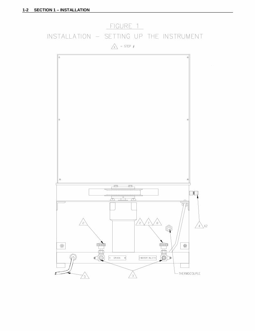
Setting Up the Instrument Refer to Figure 1 for the following steps: 1. Place the instrument on a sturdy, level table. 2. Close the supply and drain valves. 3. Connect the water supply and drain lines. 4. Connect cooling coils to a cold water source and drain, if so desired. Cooling coil use is
optional. Either connection can be used for the inlet or outlet. 5. Connect power cord to the correct voltage source. 6. Remove the slurry containers. 7. Fill the bath until it is 1/2” (12.5mm) below the brass rotating sleeves by opening up the
water supply valve. 8. Close water supply valve when appropriate water level is obtained. Note: To prevent shock hazard, connect the instrument to an electrical outlet using a three-
prong socket to provide positive ground.
1-2 SECTION 1 – INSTALLATION
SECTION 2 – OPERATING INSTRUCTIONS 2-1
Section 2 – Operating Instructions
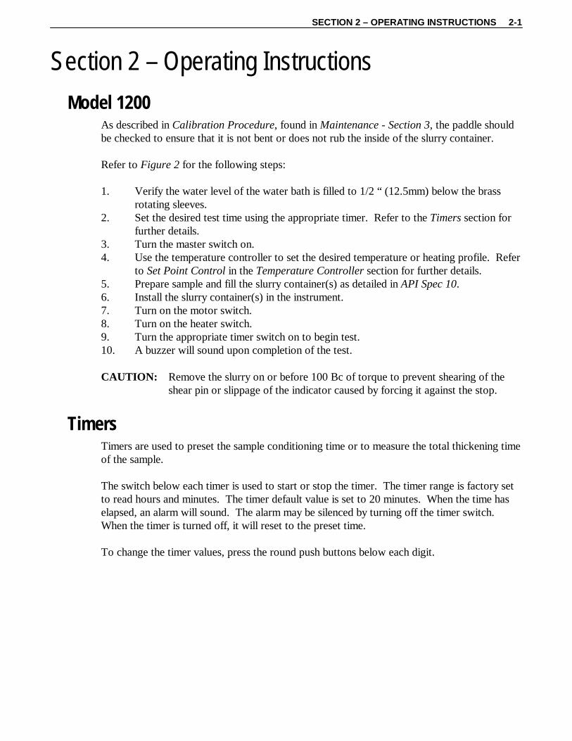
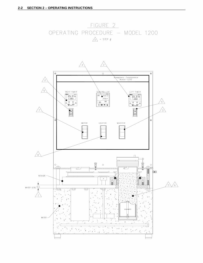
Model 1200 As described in Calibration Procedure, found in Maintenance - Section 3, the paddle should be checked to ensure that it is not bent or does not rub the inside of the slurry container. Refer to Figure 2 for the following steps: 1. Verify the water level of the water bath is filled to 1/2 “ (12.5mm) below the brass
rotating sleeves. 2. Set the desired test time using the appropriate timer. Refer to the Timers section for
further details. 3. Turn the master switch on. 4. Use the temperature controller to set the desired temperature or heating profile. Refer
to Set Point Control in the Temperature Controller section for further details. 5. Prepare sample and fill the slurry container(s) as detailed in API Spec 10. 6. Install the slurry container(s) in the instrument. 7. Turn on the motor switch. 8. Turn on the heater switch. 9. Turn the appropriate timer switch on to begin test. 10. A buzzer will sound upon completion of the test. CAUTION: Remove the slurry on or before 100 Bc of torque to prevent shearing of the
shear pin or slippage of the indicator caused by forcing it against the stop.
Timers Timers are used to preset the sample conditioning time or to measure the total thickening time of the sample. The switch below each timer is used to start or stop the timer. The timer range is factory set to read hours and minutes. The timer default value is set to 20 minutes. When the time has elapsed, an alarm will sound. The alarm may be silenced by turning off the timer switch. When the timer is turned off, it will reset to the preset time. To change the timer values, press the round push buttons below each digit.
2-2 SECTION 2 – OPERATING INSTRUCTIONS
SECTION 2 – OPERATING INSTRUCTIONS 2-3
Temperature Controller
FIGURE 3
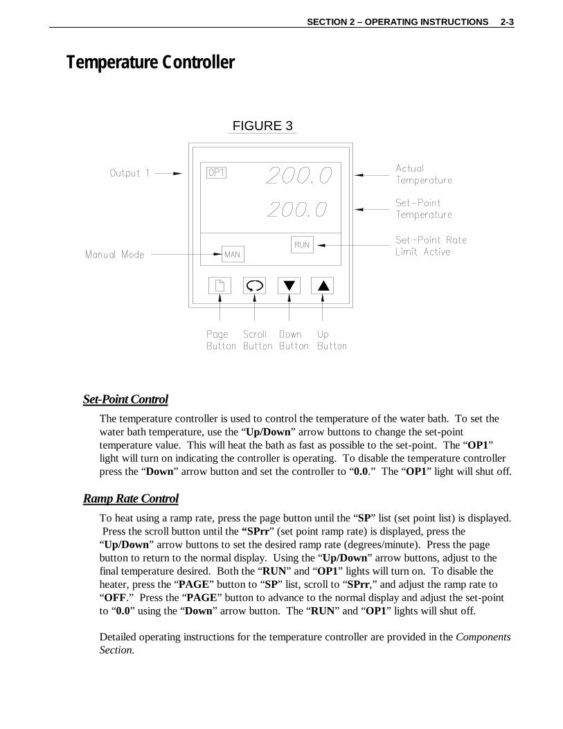
Set-Point Control
The temperature controller is used to control the temperature of the water bath. To set the water bath temperature, use the “Up/Down” arrow buttons to change the set-point temperature value. This will heat the bath as fast as possible to the set-point. The “OP1” light will turn on indicating the controller is operating. To disable the temperature controller press the “Down” arrow button and set the controller to “0.0.” The “OP1” light will shut off.
Ramp Rate Control
To heat using a ramp rate, press the page button until the “SP” list (set point list) is displayed. Press the scroll button until the “SPrr” (set point ramp rate) is displayed, press the “Up/Down” arrow buttons to set the desired ramp rate (degrees/minute). Press the page button to return to the normal display. Using the “Up/Down” arrow buttons, adjust to the final temperature desired. Both the “RUN” and “OP1” lights will turn on. To disable the heater, press the “PAGE” button to “SP” list, scroll to “SPrr,” and adjust the ramp rate to “OFF.” Press the “PAGE” button to advance to the normal display and adjust the set-point to “0.0” using the “Down” arrow button. The “RUN” and “OP1” lights will shut off. Detailed operating instructions for the temperature controller are provided in the Components Section.

SECTION 3 – MAINTENANCE 3-1
Section 3 – Maintenance
Tools Required Adjustable wrench Phillips screwdriver
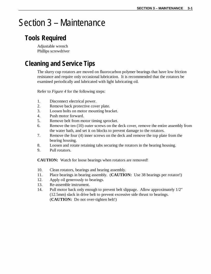
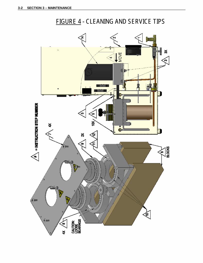
Cleaning and Service Tips The slurry cup rotators are moved on fluorocarbon polymer bearings that have low friction resistance and require only occasional lubrication. It is recommended that the rotators be examined periodically and lubricated with light lubricating oil. Refer to Figure 4 for the following steps: 1. Disconnect electrical power. 2. Remove back protective cover plate. 3. Loosen bolts on motor mounting bracket. 4. Push motor forward. 5. Remove belt from motor timing sprocket. 6. Remove the ten (10) outer screws on the deck cover, remove the entire assembly from
the water bath, and set it on blocks to prevent damage to the rotators. 7. Remove the four (4) inner screws on the deck and remove the top plate from the
bearing housing. 8. Loosen and rotate retaining tabs securing the rotators in the bearing housing. 9. Pull rotators. CAUTION: Watch for loose bearings when rotators are removed! 10. Clean rotators, bearings and bearing assembly. 11. Place bearings in bearing assembly. (CAUTION: Use 38 bearings per rotator!) 12. Apply oil generously to bearings. 13. Re-assemble instrument. 14. Pull motor back only enough to prevent belt slippage. Allow approximately 1/2"
(12.5mm) slack in drive belt to prevent excessive side thrust to bearings. (CAUTION: Do not over-tighten belt!)
3-2 SECTION 3 – MAINTENANCE
FIGURE 4 - CLEANING AND SERVICE TIPS
SECTION 3 – MAINTENANCE 3-3
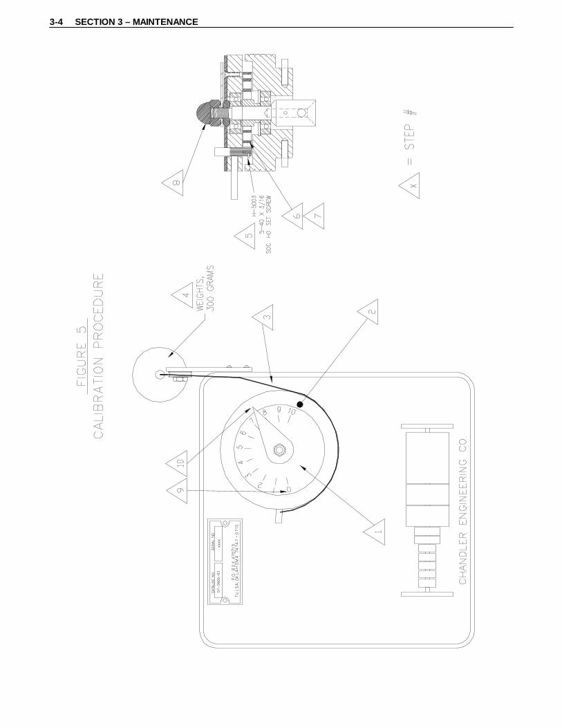
Calibration Procedure Before calibration and operation of the instrument, the paddle should be tested for excessive friction by running the slurry container without cement inside. If the paddle is bent so that it rubs on the side, appreciable movement will be shown on the indicator. The bearings in the slurry-indicating lid should be checked for excessive friction. Any abnormality should be corrected before proceeding with the instrument calibration. Calibration and operation of the instrument is described in API Spec 10. This instrument is equipped with a calibrating spring and can be calibrated using the calibration device and adapter. The adapter is placed with screws on the right-rear side of the calibration device, and the ring rests on top of the lid. The roller located on the right-front side of the calibration device is raised to a position so that the cord is level with the lid. Refer to Figure 5 for the following: 1. Place the container lid on the calibration assembly. 2. Place the adapter ring on the container lid assembly. 3. Place the cord counterclockwise around the lid and attach 300 grams of weight. 4. Pull the weight down slightly and release a few times to obtain an average reading.
The indicator should read “7.5” (75 Bc ± 5 Bc). 5. Corrections can be made by turning the small set screw to loosen the spring clamp
inside the lid. 6. Slide the spring to the right when the indicator reads below “75” Bc. 7. Slide the spring to the left when the indicator reads above “75” Bc. 8. After the spring is adjusted, loosen the top nut and set the indicator hand to “0” Bc. 9. The “75” Bc must be re-checked. 10. Repeat steps 1 through 9 until “0” and “75” Bc are correctly indicated within ± 5 Bc. 11. When the spring has been adjusted to read 75 Bc with 300 grams, several points
should be checked, such as 25 Bc – 100 grams, 50 Bc – 200 grams, and 100 Bc – 400 grams.
3-4 SECTION 3 – MAINTENANCE
SECTION 3 – MAINTENANCE 3-5
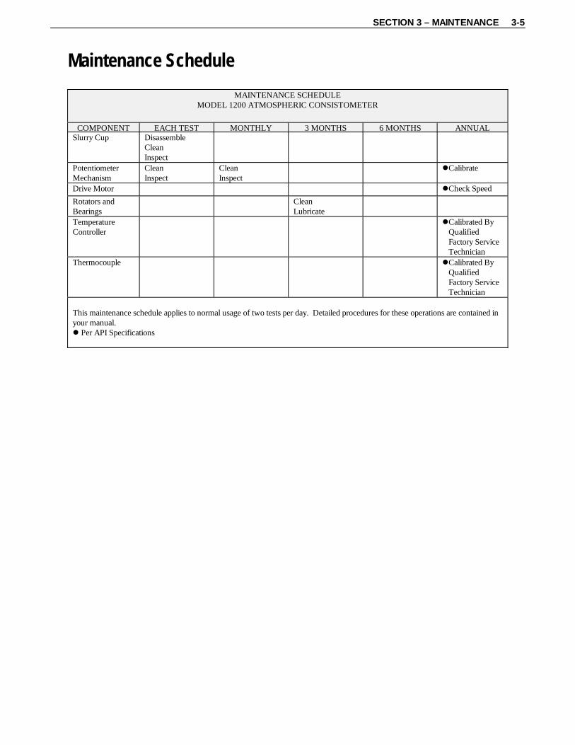
Maintenance Schedule
MAINTENANCE SCHEDULE MODEL 1200 ATMOSPHERIC CONSISTOMETER
COMPONENT EACH TEST MONTHLY 3 MONTHS 6 MONTHS ANNUALSlurry Cup Disassemble
Clean Inspect
Potentiometer Mechanism
Clean Inspect
Clean Inspect
Calibrate
Drive Motor Check Speed
Rotators and Bearings
Clean Lubricate
Temperature Controller
Calibrated By Qualified Factory Service Technician
Thermocouple Calibrated By Qualified Factory Service Technician
This maintenance schedule applies to normal usage of two tests per day. Detailed procedures for these operations are contained in your manual. Per API Specifications

SECTION 4 – TROUBLESHOOTING GUIDE 4-1
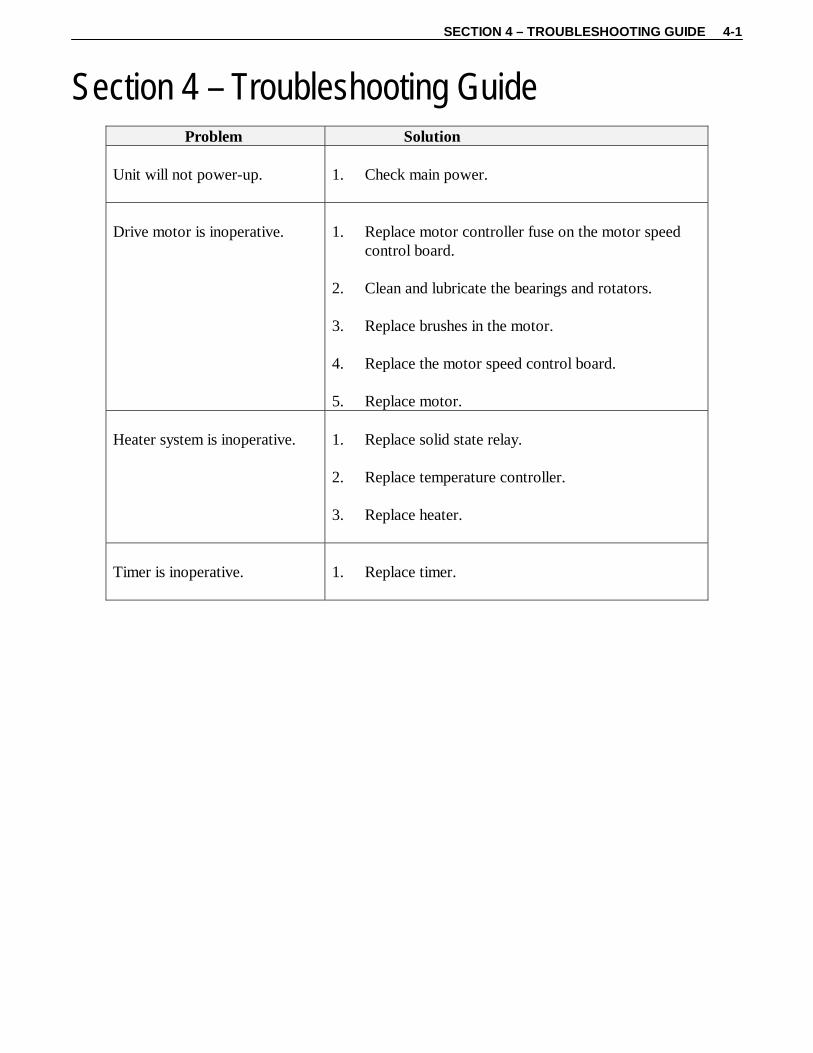
Section 4 – Troubleshooting Guide
Problem Solution Unit will not power-up.
1. Check main power.
Drive motor is inoperative.
1. Replace motor controller fuse on the motor speed
control board. 2. Clean and lubricate the bearings and rotators. 3. Replace brushes in the motor. 4. Replace the motor speed control board. 5. Replace motor.
Heater system is inoperative.
1. Replace solid state relay. 2. Replace temperature controller. 3. Replace heater.
Timer is inoperative.
1. Replace timer.

SECTION 5 – REPLACEMENT PARTS 5-1
-1200-REPL_PARTS REV C
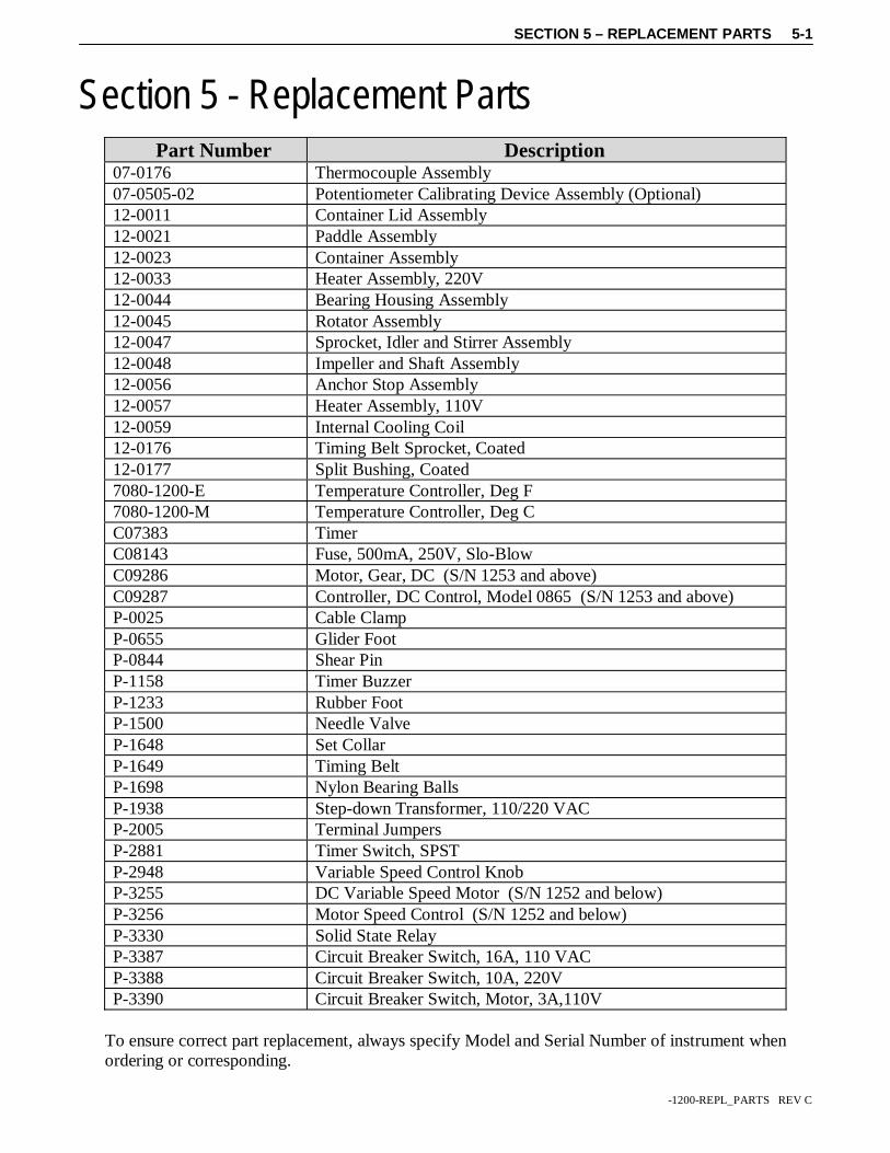
Section 5 - Replacement Parts
Part Number Description 07-0176 Thermocouple Assembly 07-0505-02 Potentiometer Calibrating Device Assembly (Optional) 12-0011 Container Lid Assembly 12-0021 Paddle Assembly 12-0023 Container Assembly 12-0033 Heater Assembly, 220V 12-0044 Bearing Housing Assembly 12-0045 Rotator Assembly 12-0047 Sprocket, Idler and Stirrer Assembly 12-0048 Impeller and Shaft Assembly 12-0056 Anchor Stop Assembly 12-0057 Heater Assembly, 110V 12-0059 Internal Cooling Coil 12-0176 Timing Belt Sprocket, Coated 12-0177 Split Bushing, Coated 7080-1200-E Temperature Controller, Deg F 7080-1200-M Temperature Controller, Deg C C07383 Timer C08143 Fuse, 500mA, 250V, Slo-Blow C09286 Motor, Gear, DC (S/N 1253 and above) C09287 Controller, DC Control, Model 0865 (S/N 1253 and above) P-0025 Cable Clamp P-0655 Glider Foot P-0844 Shear Pin P-1158 Timer Buzzer P-1233 Rubber Foot P-1500 Needle Valve P-1648 Set Collar P-1649 Timing Belt P-1698 Nylon Bearing Balls P-1938 Step-down Transformer, 110/220 VAC P-2005 Terminal Jumpers P-2881 Timer Switch, SPST P-2948 Variable Speed Control Knob P-3255 DC Variable Speed Motor (S/N 1252 and below) P-3256 Motor Speed Control (S/N 1252 and below) P-3330 Solid State Relay P-3387 Circuit Breaker Switch, 16A, 110 VAC P-3388 Circuit Breaker Switch, 10A, 220V P-3390 Circuit Breaker Switch, Motor, 3A,110V
To ensure correct part replacement, always specify Model and Serial Number of instrument when ordering or corresponding.

5-2 SECTION 5 – REPLACEMENT PARTS
-1200-REPL_PARTS REV C
This page is intentionally left blank.

SECTION 6 – DRAWINGS AND SCHEMATICS 6-1
-1200-DWGS REV A
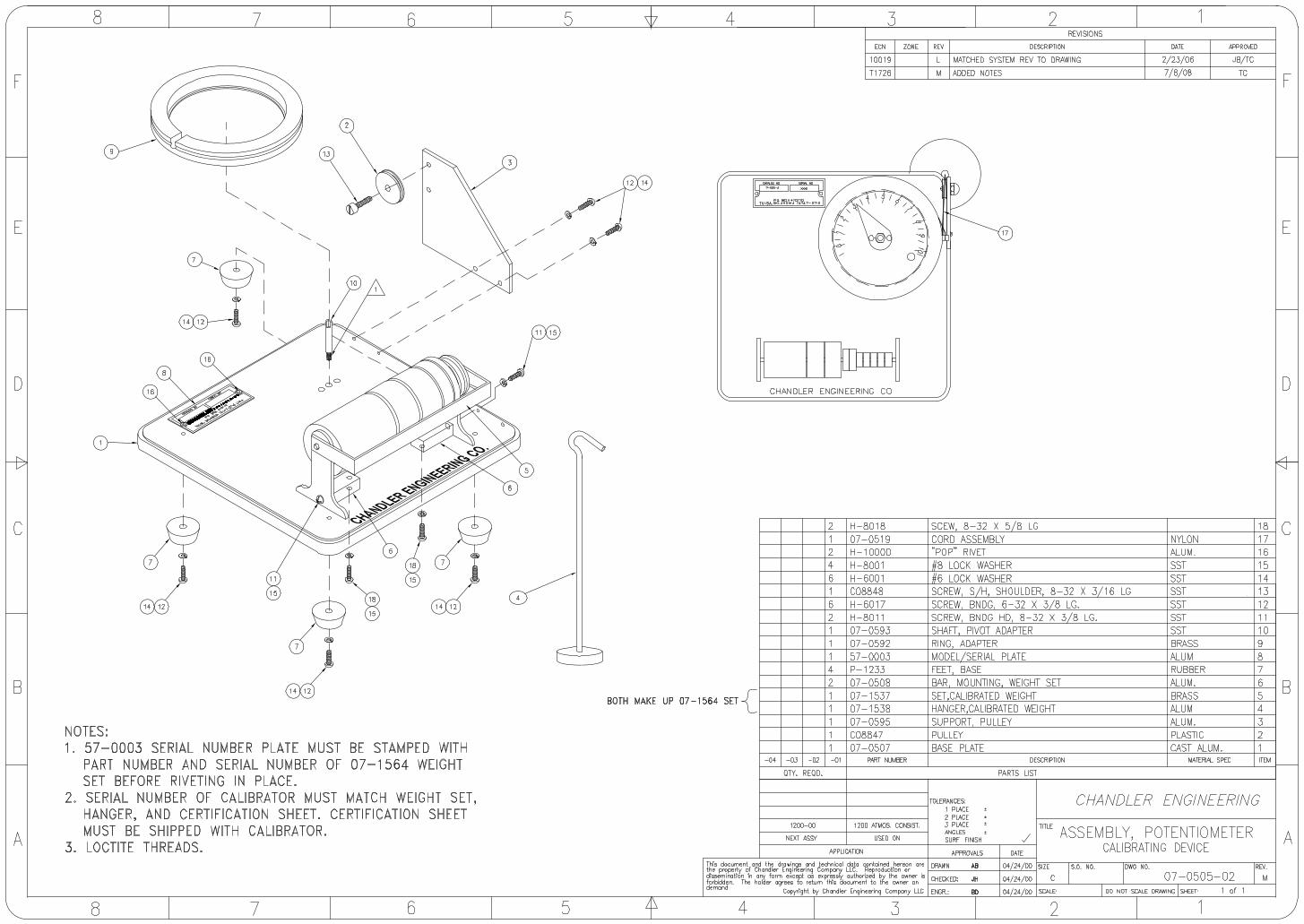
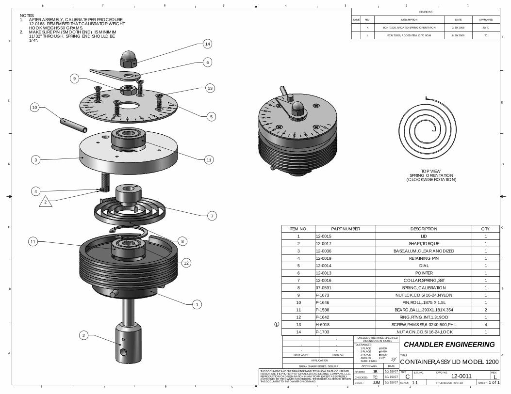
Section 6 - Drawings and Schematics
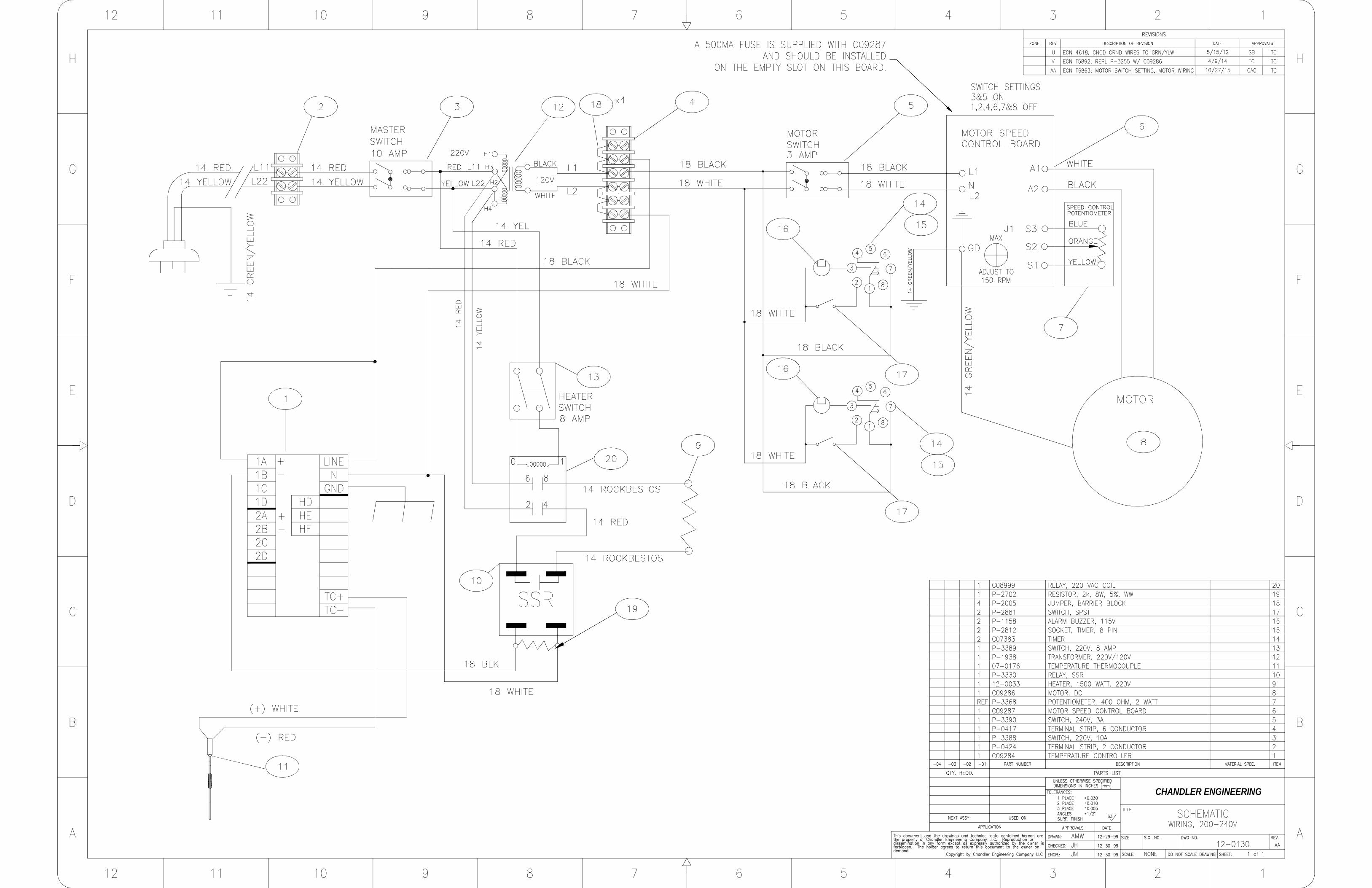
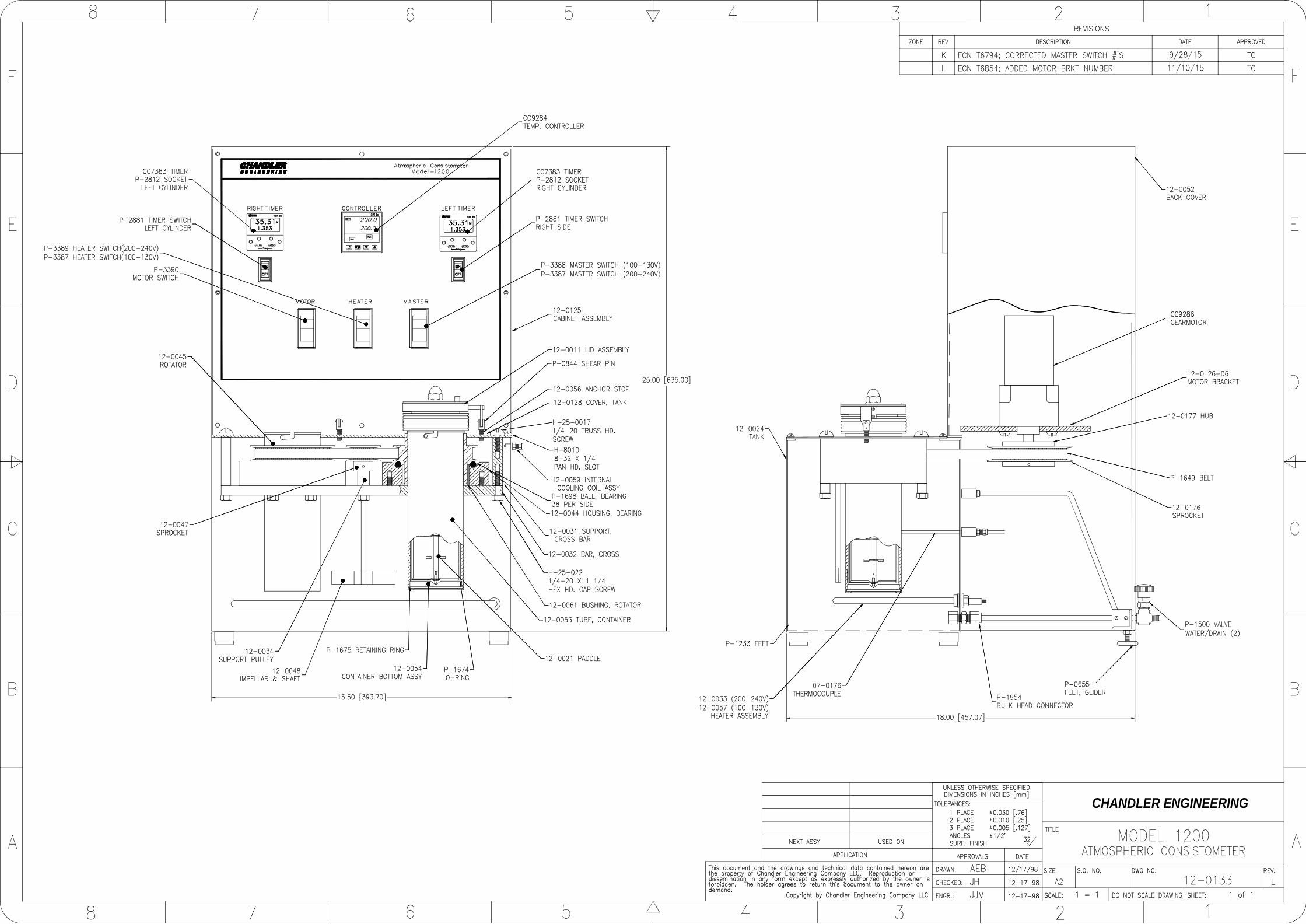
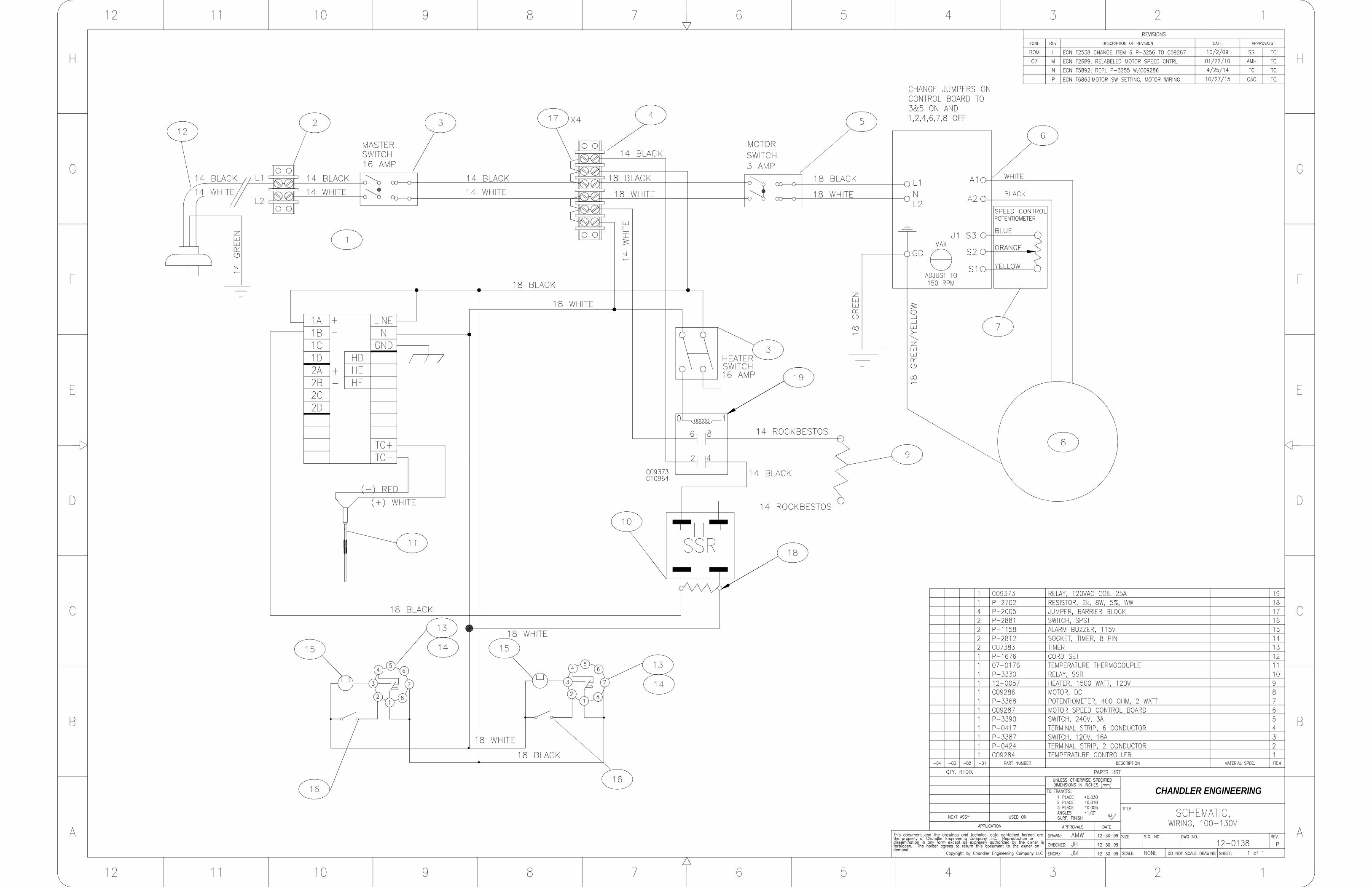
Drawing Number Description 07-0505-02 Potentiometer Calibration Device Assembly 12-0011 Container Lid Assembly 12-0130 Wiring Schematic, 200-240VAC 12-0133 Model 1200 Atmospheric Consistometer 12-0138 Wiring Schematic, 100-130VAC

TOP VIEW SPRING ORIENTATION
(CLOCKWISE ROTATION)
.
10/18/07
D
C
B
AA
B
C
D
12345678
8 7 6 5 4 3 2
.
..
CONTAINER,ASSY LID MODEL 1200
1
THIS DOCUMENT TO THE OWNER ON DEMAND.
E
F
E
F
S.O. NO.
SCALE:
SIZE
TITLE
DWG NO.
SHEET:
REV.
NEXT ASSY
APPLICATION
USED ON
ENGR.:
CHECKED:
DRAWN:
APPROVALS DATE
UNLESS OTHERWISE SPECIFIEDDIMENSIONS IN INCHES
TOLERANCES:
SURF. FINISHANGLES
1 PLACE
0.0052 PLACE
AUTHORIZED BY THE OWNER IS FORBIDDEN. THE HOLDER AGREES TO RETURN
3 PLACE
0.0300.010
REPRODUCTION OR DISSEMINATION IN ANY FORM EXCEPT AS EXPRESSLY
BREAK SHARP EDGES, DEBURR
JB
.CHANDLER ENGINEERING
TC
.
63
JJM
10/18/07
12-0011C10/19/07 L1 of 11:1
THIS DOCUMENT AND THE DRAWINGS AND TECHNICAL DATA CONTAINED HEREON ARE THE PROPERTY OF CHANDLER ENGINEERING COMPANY, L.L.C.
1/2
TITLE BLOCK REV: 1.0
REVISIONS
ZONE REV. DESCRIPTION DATENOTES:
AFTER ASSEMBLY, CALIBRATE PER PROCEDURE 1.12-0168. REMEMBER THAT CALIBRATOR WEIGHT
K
APPROVED
1/4".11/32" THROUGH. SPRING END SHOULD BE
ECN T1526, UPDATED SPRING ORIENTATION 3/10/2008 JB/TC
L ECN T1858; ADDED ITEM 13 TO BOM 8/20/2008 TC
HOOK WEIGHS 50 GRAMS.MAKE SURE PIN (SMOOTH END) IS MINIMIM 2.
L
ITEM NO. PART NUMBER DESCRIPTION QTY.
1 12-0015 LID 1
2 12-0017 SHAFT,TORQUE 1
3 12-0036 BASE,ALUM,CLEAR ANODIZED 1
4 12-0019 RETAINING PIN 1
5 12-0014 DIAL 1
6 12-0013 POINTER 1
7 12-0016 COLLAR,SPRING,SST 1
8 07-0591 SPRING,CALIBRATION 1
9 P-1673 NUT,LCK,CD,5/16-24,NYLON 1
10 P-1646 PIN,ROLL,.1875 X 1.5L 1
11 P-1588 BEARG,BALL,.393X1.181X.354 2
12 P-1642 RING,RTNG,INT,1.319OD 1
13 H-6018 SCREW,FHMS,SS,6-32X0.500,PHIL 4
14 P-1703 .NUT,ACN,CD,5/16-24,LOCK 1
11
14
6
13
5
9
11
4
7
8
12
1
2
3
10
2
CHANDLER ENGINEERING
CHANDLER ENGINEERING
CHANDLER ENGINEERING
AEROSPACE & DEFENSE
2001 North Indianwood Avenue, Broken Arrow, OK 74012 Phone: 918-250-7200 Fax: 918-459-0165
© 2008, by AMETEK, Inc. All rights reserved. e-mail: [email protected] www.chandlereng.com
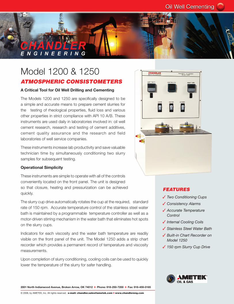
Model 1200 & 1250ATMOSPHERIC CONSISTOMETERSA Critical Tool for Oil Well Drilling and Cementing
The Models 1200 and 1250 are specifically designed to be a simple and accurate means to prepare cement slurries for the testing of rheological properties, fluid loss and various other properties in strict compliance with API 10 A/B. These instruments are used daily in laboratories involved in: oil well cement research, research and testing of cement additives, cement quality assurance and the research and field laboratories of well service companies.
These instruments increase lab productivity and save valuable technician time by simultaneously conditioning two slurry samples for subsequent testing.
Operational Simplicity
These instruments are simple to operate with all of the controls conveniently located on the front panel. The unit is designed so that closure, heating and pressurization can be achieved quickly.
The slurry cup drive automatically rotates the cup at the required, standard rate of 150 rpm. Accurate temperature control of the stainless steel water bath is maintained by a programmable temperature controller as well as a motor-driven stirring mechanism in the water bath that eliminates hot spots on the slurry cups.
Indicators for each viscosity and the water bath temperature are readily visible on the front panel of the unit. The Model 1250 adds a strip chart recorder which provides a permanent record of temperature and viscosity measurements.
Upon completion of slurry conditioning, cooling coils can be used to quickly lower the temperature of the slurry for safer handling.
FEATURES
3 Two Conditioning Cups
3 Consistency Alarms
3 Accurate Temperature Control
3 Internal Cooling Coils
3 Stainless Steel Water Bath
3 Built-in Chart Recorder on Model 1250
3 150 rpm Slurry Cup Drive
Printed in the U.S.A. © 2008, by AMETEK, Inc. All rights reserved. XM808PDF (360000)
2001 North Indianwood Avenue, Broken Arrow, OK 74012 Tel: +1 918-250-7200 Fax: +1 918-459-0165e-mail: [email protected] www.chandlereng.com
Houston Sales and Services4903 W. Sam Houston Parkway, N., Suite A-400, Houston, TX 77041 Tel: +1 713-466-4900 Fax: +1 713-849-1924
Model 1200 & 1250
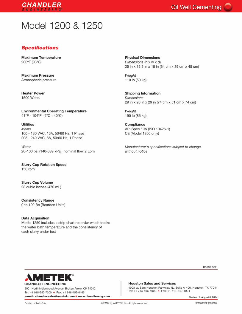
Specifications
Maximum Temperature200ºF (93ºC)
Maximum Pressure Atmospheric pressure
Heater Power 1500 Watts
Environmental Operating Temperature 41°F - 104ºF (5ºC - 40ºC)
UtilitiesMains 100 - 130 VAC, 16A, 50/60 Hz, 1 Phase208 - 240 VAC, 8A, 50/60 Hz, 1 Phase
Water 20-100 psi (140-689 kPa); nominal flow 2 Lpm
Slurry Cup Rotation Speed150 rpm
Slurry Cup Volume28 cubic inches (470 mL)
Consistency Range 0 to 100 Bc (Bearden Units)
Data Acquisition Model 1250 includes a strip chart recorder which tracks the water bath temperature and the consistency of each slurry under test
Physical DimensionsDimensions (h x w x d) 25 in x 15.5 in x 18 in (64 cm x 39 cm x 45 cm)
Weight110 lb (50 kg)
Shipping InformationDimensions 29 in x 20 in x 29 in (74 cm x 51 cm x 74 cm)
Weight 190 lb (86 kg)
ComplianceAPI Spec 10A (ISO 10426-1) CE (Model 1200 only)
Manufacturer’s specifications subject to change without notice
R0109.002
Revision 1: August 6, 2014