Embed Size (px)
Citation preview
PMP6024 100-240VAC Input, 60W, 2-string, PWM Dimmable LED Driver Test Report
July, 2014
100-240VAC Input, 60W, 2-string, PWM Dimmable LED Driver
1 Introduction
This UCC28811 reference design presents the UCC28811 AC-DC controller and the LM3409HV DC-DC controller driving two strings of LEDs up to 700mA each in an isolated flyback plus buck configuration. The LED current is controlled by a PWM dimming pulse signal. The LED current can be dimmed to 1/1000 at 1% PWM dimming duty cycle. The features of UCC28811 include Transition Mode Control, Single Stage Power Factor Correction, Over Voltage Protection, Low Start Up Current.
2 Description
This reference design provides a high-brightness LED driver based on the configured as an isolated flyback converter plus two buck converters. The flyback converter provides an isolated 50V bus and a 15V bias voltage for secondary controllers. The flyback converter also achieves input power factor correction. The LED currents are regulated by two LM3409 based buck converters which convert 50V bus voltage to LED voltages. A PWM signal controls the LED current reference of the buck converters. This reference design is designed to operate with an input voltage in the range of 100VAC to 240VAC. This
design is set up for two strings of LEDs with current up to 700mA each. The typical LED stack voltage is 45V.
2.1 Flyback Power Supply Description
This UCC28811 based flyback converter operates at critical conduction mode. The UCC28811 PWM circuit is self-oscillating with the turn-on being governed by a transformer zero energy detector (TZE pin) and the turn-off being governed by the current sense comparator. MOSFET Q1 provides the IC start up current. Once the output voltage rises, the bias voltage from the transformer aux winding (7-5) starts providing current for the IC. When this bias voltage is above 10.6V, it turns on Q5 to discharge the gate of Q1.
The power factor correction is achieved by sensing the rectified AC voltage on VINS pin through the resistor divider R20, R24, R45. The peak primary current of each switch cycle is proportional to the VINS pin voltage. The over voltage protection (OVP) circuit consists of Q7 and U4. It pulls the IC VSENSE pin up when the voltage at the reference pin of shunt regulator U4 is over 1.24V.
2.2 Buck Converter Description
The second stage of this reference design includes two LM3409 based buck converters. LM3409 is a P channel MOSFET buck controller. So it is able to operate at close to 100% duty cycle. The LED current is set by the voltage at the IADJ pin. A 3.3V 10KHz PWM signal is applied at connectors J4 and J5. This PWM signal is filtered by RC filters R77 C68 and R87 C78 to generate a constant DC voltage at IADJ pins. This IADJ voltage is proportional to the PWM signal duty cycle.
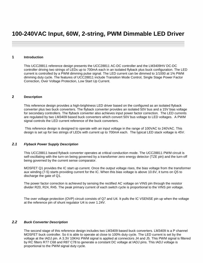
2.3 Test Setup
AC Input
Black
Black
Red
Red
3.3 V 10KHz
Variable DC
REFERNCE DESIGN BOARD
LED
Current
LED
VoltagePin
PF
Brown Brown
J9
J6
J13
J11J4J5
J1
J3
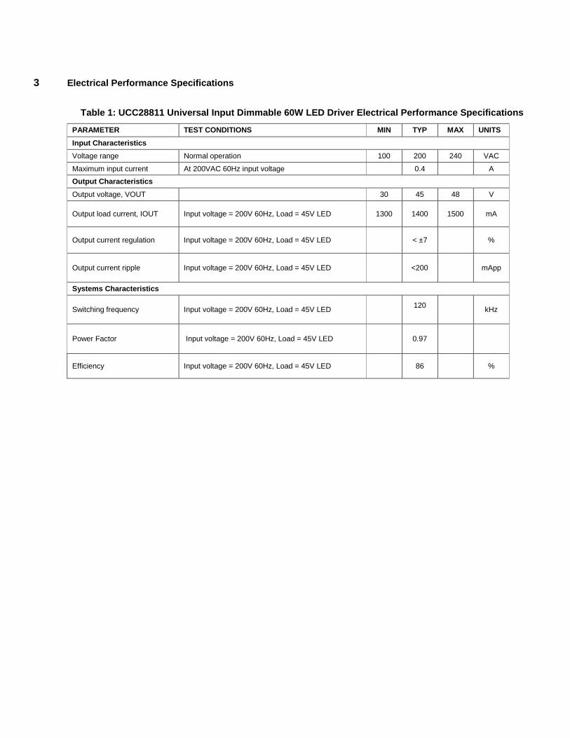
3 Electrical Performance Specifications
Table 1: UCC28811 Universal Input Dimmable 60W LED Driver Electrical Performance Specifications
PARAMETER TEST CONDITIONS MIN TYP MAX UNITS
Input Characteristics
Voltage range Normal operation 100 200 240 VAC
Maximum input current At 200VAC 60Hz input voltage 0.4 A
Output Characteristics
Output voltage, VOUT 30 45 48 V
Output load current, IOUT Input voltage = 200V 60Hz, Load = 45V LED
1300 1400 1500 mA
Output current regulation Input voltage = 200V 60Hz, Load = 45V LED
< ±7 %
Output current ripple Input voltage = 200V 60Hz, Load = 45V LED
<200
mApp
Systems Characteristics
Switching frequency Input voltage = 200V 60Hz, Load = 45V LED 120
kHz
Power Factor Input voltage = 200V 60Hz, Load = 45V LED 0.97
Efficiency Input voltage = 200V 60Hz, Load = 45V LED 86 %
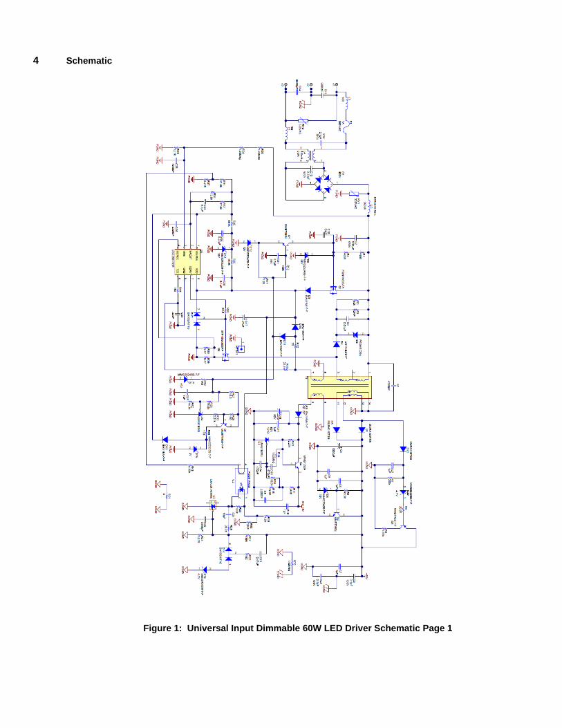
4 Schematic
Figure 1: Universal Input Dimmable 60W LED Driver Schematic Page 1
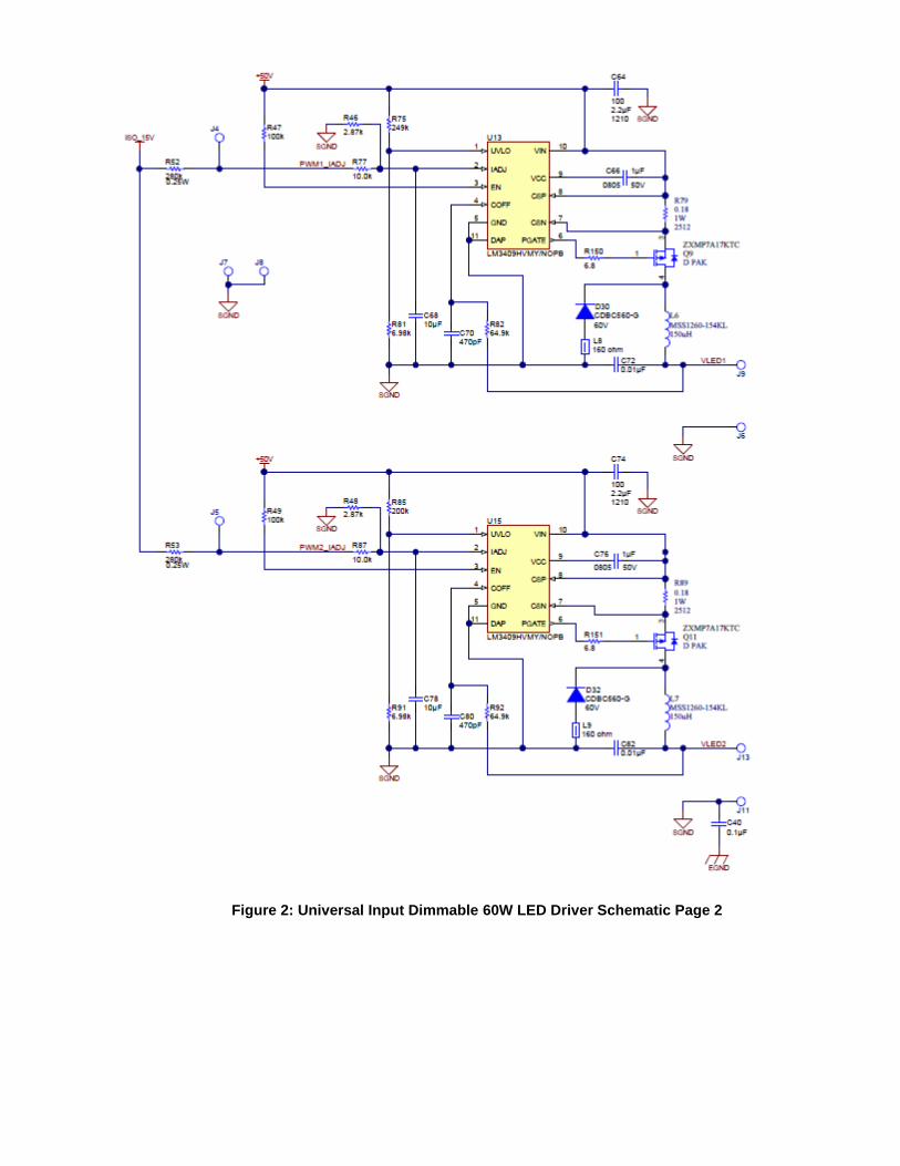
Figure 2: Universal Input Dimmable 60W LED Driver Schematic Page 2
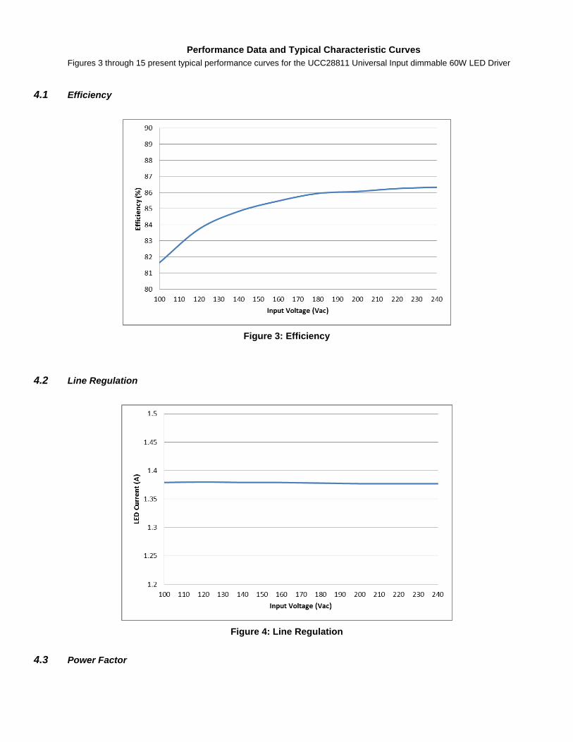
Performance Data and Typical Characteristic Curves
Figures 3 through 15 present typical performance curves for the UCC28811 Universal Input dimmable 60W LED Driver
4.1 Efficiency
Figure 3: Efficiency
4.2 Line Regulation
Figure 4: Line Regulation
4.3 Power Factor
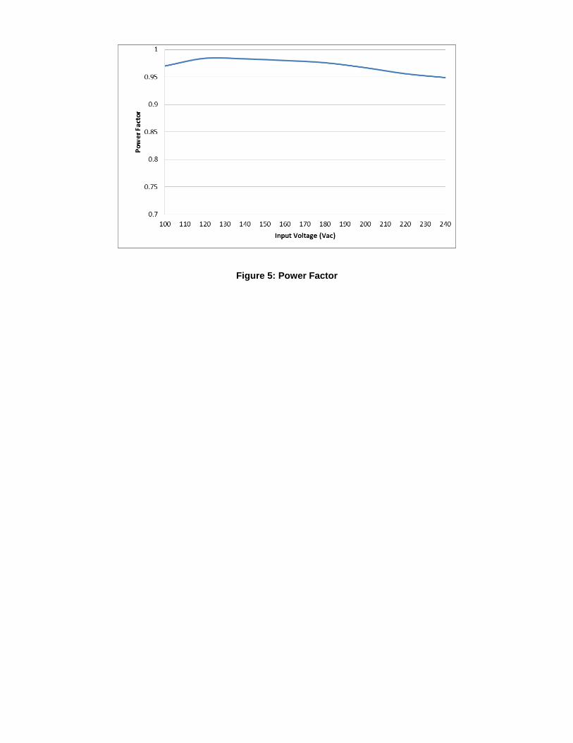
Figure 5: Power Factor
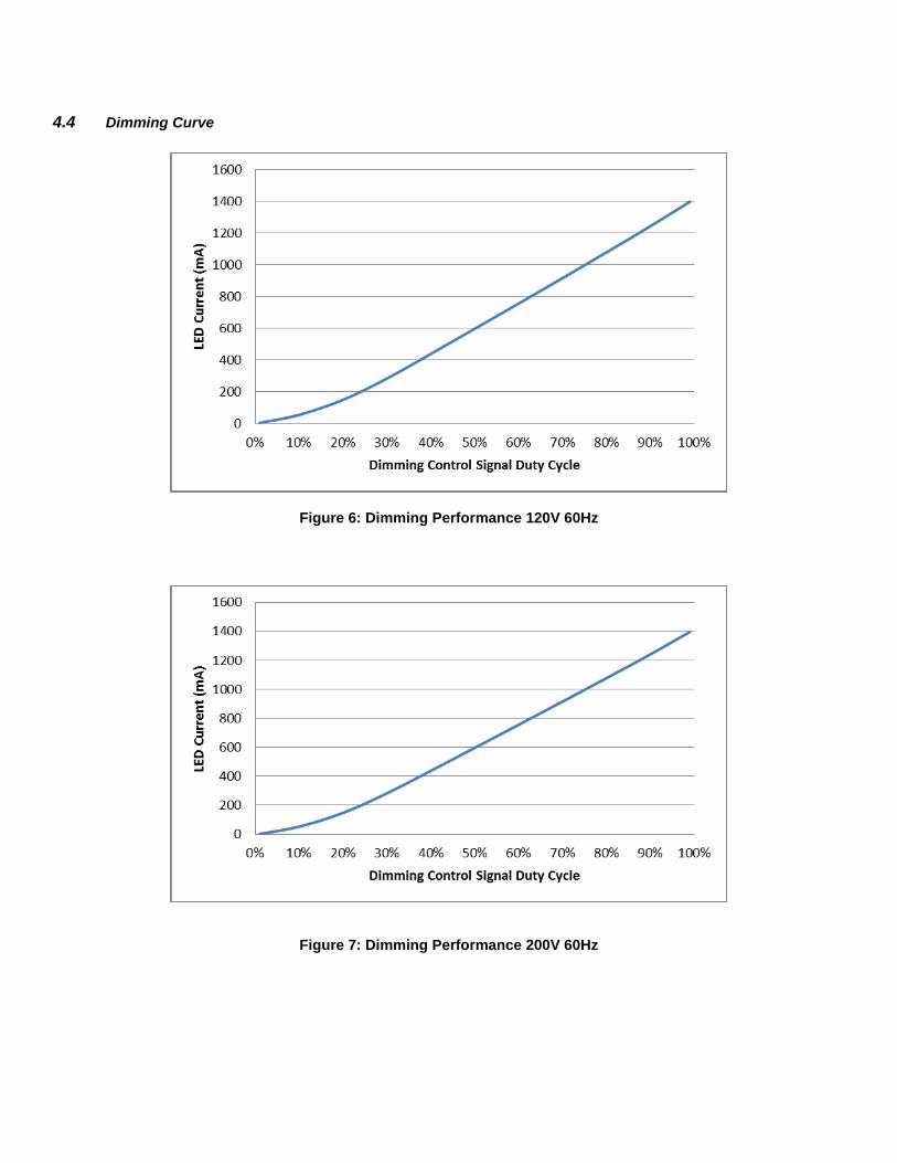
4.4 Dimming Curve
Figure 6: Dimming Performance 120V 60Hz
Figure 7: Dimming Performance 200V 60Hz
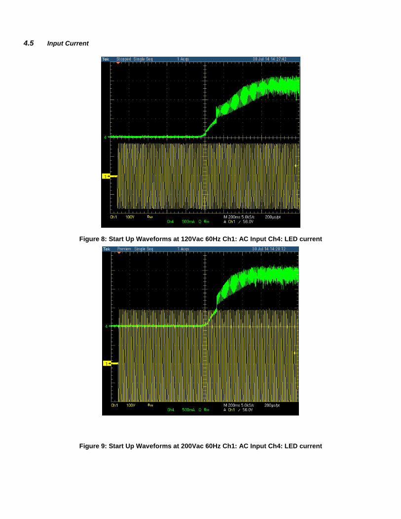
4.5 Input Current
Figure 8: Start Up Waveforms at 120Vac 60Hz Ch1: AC Input Ch4: LED current
Figure 9: Start Up Waveforms at 200Vac 60Hz Ch1: AC Input Ch4: LED current
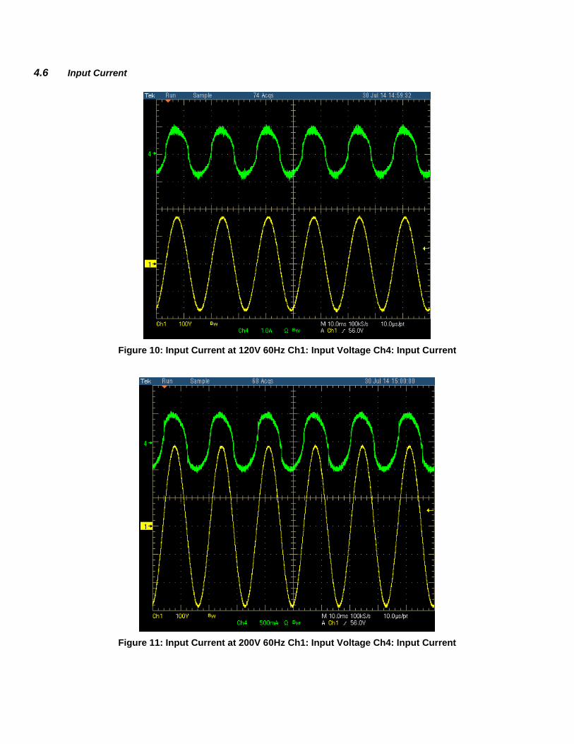
4.6 Input Current
Figure 10: Input Current at 120V 60Hz Ch1: Input Voltage Ch4: Input Current
Figure 11: Input Current at 200V 60Hz Ch1: Input Voltage Ch4: Input Current
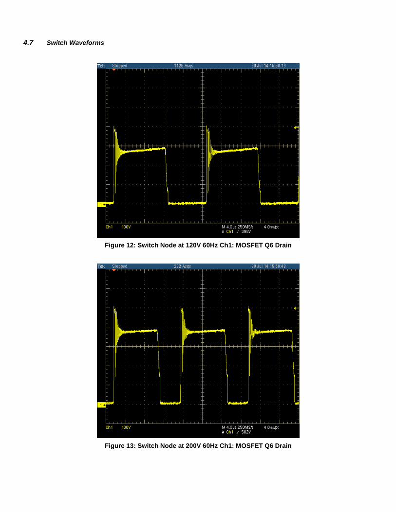
4.7 Switch Waveforms
Figure 12: Switch Node at 120V 60Hz Ch1: MOSFET Q6 Drain
Figure 13: Switch Node at 200V 60Hz Ch1: MOSFET Q6 Drain
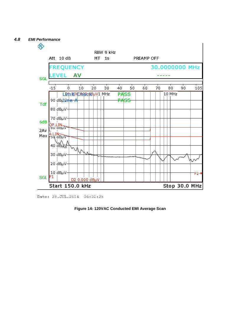
4.8 EMI Performance
Figure 14: 120VAC Conducted EMI Average Scan
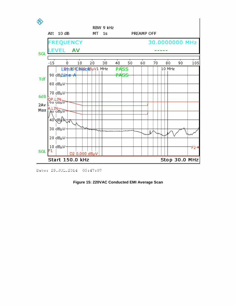
Figure 15: 220VAC Conducted EMI Average Scan
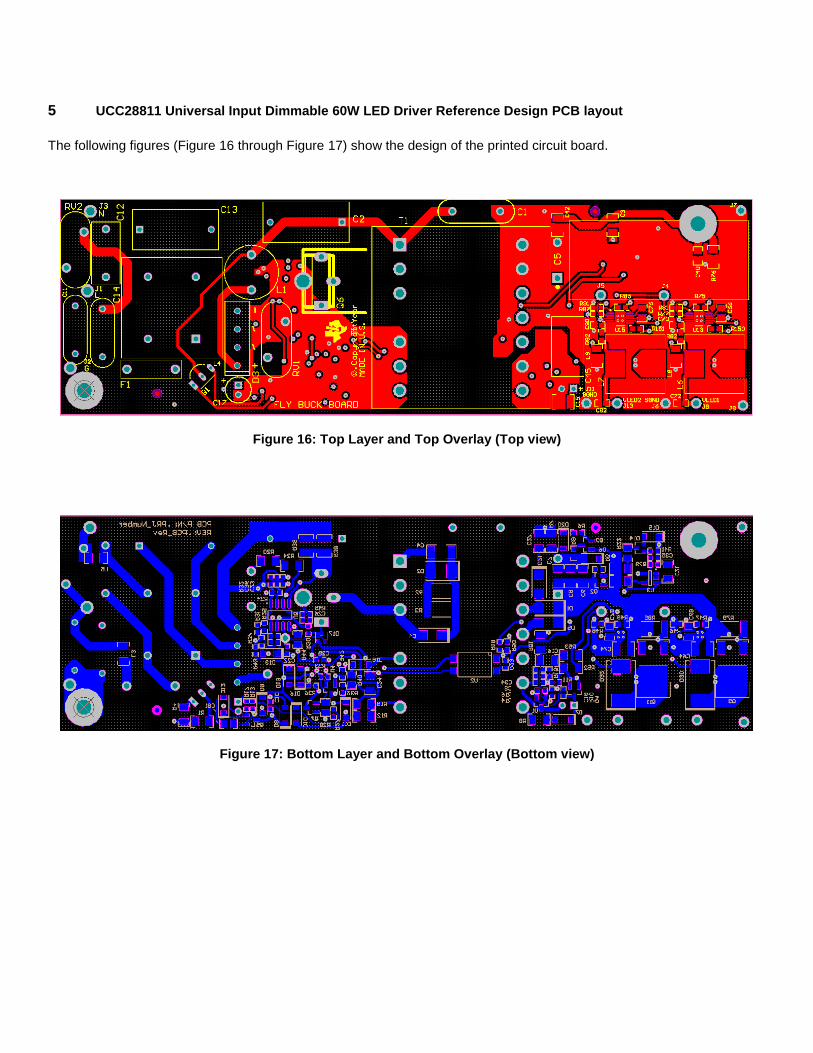
5 UCC28811 Universal Input Dimmable 60W LED Driver Reference Design PCB layout
The following figures (Figure 16 through Figure 17) show the design of the printed circuit board.
Figure 16: Top Layer and Top Overlay (Top view)
Figure 17: Bottom Layer and Bottom Overlay (Bottom view)
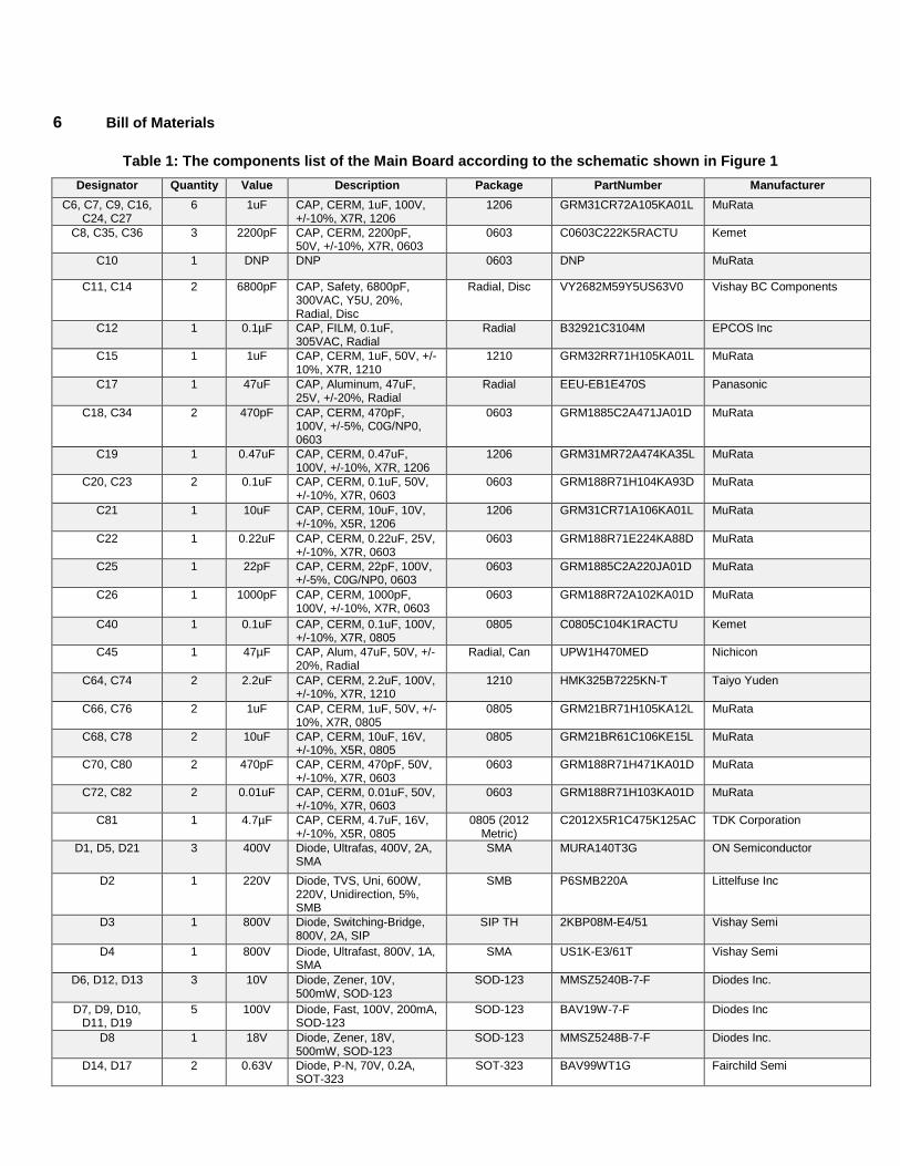
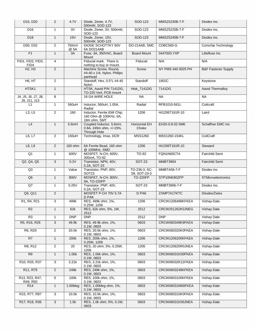
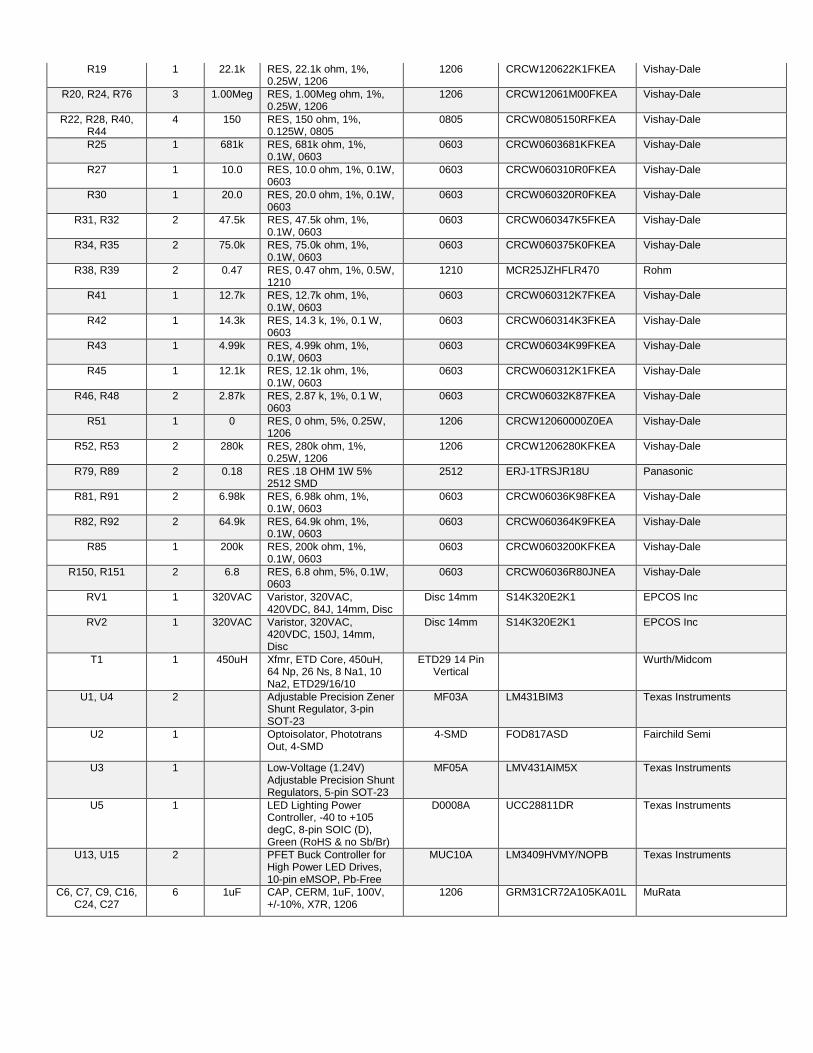
6 Bill of Materials
Table 1: The components list of the Main Board according to the schematic shown in Figure 1
Designator Quantity Value Description Package PartNumber Manufacturer
C6, C7, C9, C16, C24, C27
6 1uF CAP, CERM, 1uF, 100V, +/-10%, X7R, 1206
1206 GRM31CR72A105KA01L MuRata
C8, C35, C36 3 2200pF CAP, CERM, 2200pF, 50V, +/-10%, X7R, 0603
0603 C0603C222K5RACTU Kemet
C10 1 DNP DNP 0603 DNP MuRata
C11, C14 2 6800pF CAP, Safety, 6800pF, 300VAC, Y5U, 20%, Radial, Disc
Radial, Disc VY2682M59Y5US63V0 Vishay BC Components
C12 1 0.1µF CAP, FILM, 0.1uF, 305VAC, Radial
Radial B32921C3104M EPCOS Inc
C15 1 1uF CAP, CERM, 1uF, 50V, +/-10%, X7R, 1210
1210 GRM32RR71H105KA01L MuRata
C17 1 47uF CAP, Aluminum, 47uF, 25V, +/-20%, Radial
Radial EEU-EB1E470S Panasonic
C18, C34 2 470pF CAP, CERM, 470pF, 100V, +/-5%, C0G/NP0, 0603
0603 GRM1885C2A471JA01D MuRata
C19 1 0.47uF CAP, CERM, 0.47uF, 100V, +/-10%, X7R, 1206
1206 GRM31MR72A474KA35L MuRata
C20, C23 2 0.1uF CAP, CERM, 0.1uF, 50V, +/-10%, X7R, 0603
0603 GRM188R71H104KA93D MuRata
C21 1 10uF CAP, CERM, 10uF, 10V, +/-10%, X5R, 1206
1206 GRM31CR71A106KA01L MuRata
C22 1 0.22uF CAP, CERM, 0.22uF, 25V, +/-10%, X7R, 0603
0603 GRM188R71E224KA88D MuRata
C25 1 22pF CAP, CERM, 22pF, 100V, +/-5%, C0G/NP0, 0603
0603 GRM1885C2A220JA01D MuRata
C26 1 1000pF CAP, CERM, 1000pF, 100V, +/-10%, X7R, 0603
0603 GRM188R72A102KA01D MuRata
C40 1 0.1uF CAP, CERM, 0.1uF, 100V, +/-10%, X7R, 0805
0805 C0805C104K1RACTU Kemet
C45 1 47µF CAP, Alum, 47uF, 50V, +/-20%, Radial
Radial, Can UPW1H470MED Nichicon
C64, C74 2 2.2uF CAP, CERM, 2.2uF, 100V, +/-10%, X7R, 1210
1210 HMK325B7225KN-T Taiyo Yuden
C66, C76 2 1uF CAP, CERM, 1uF, 50V, +/-10%, X7R, 0805
0805 GRM21BR71H105KA12L MuRata
C68, C78 2 10uF CAP, CERM, 10uF, 16V, +/-10%, X5R, 0805
0805 GRM21BR61C106KE15L MuRata
C70, C80 2 470pF CAP, CERM, 470pF, 50V, +/-10%, X7R, 0603
0603 GRM188R71H471KA01D MuRata
C72, C82 2 0.01uF CAP, CERM, 0.01uF, 50V, +/-10%, X7R, 0603
0603 GRM188R71H103KA01D MuRata
C81 1 4.7µF CAP, CERM, 4.7uF, 16V, +/-10%, X5R, 0805
0805 (2012 Metric)
C2012X5R1C475K125AC TDK Corporation
D1, D5, D21 3 400V Diode, Ultrafas, 400V, 2A, SMA
SMA MURA140T3G ON Semiconductor
D2 1 220V Diode, TVS, Uni, 600W, 220V, Unidirection, 5%, SMB
SMB P6SMB220A Littelfuse Inc
D3 1 800V Diode, Switching-Bridge, 800V, 2A, SIP
SIP TH 2KBP08M-E4/51 Vishay Semi
D4 1 800V Diode, Ultrafast, 800V, 1A, SMA
SMA US1K-E3/61T Vishay Semi
D6, D12, D13 3 10V Diode, Zener, 10V, 500mW, SOD-123
SOD-123 MMSZ5240B-7-F Diodes Inc.
D7, D9, D10, D11, D19
5 100V Diode, Fast, 100V, 200mA, SOD-123
SOD-123 BAV19W-7-F Diodes Inc
D8 1 18V Diode, Zener, 18V, 500mW, SOD-123
SOD-123 MMSZ5248B-7-F Diodes Inc.
D14, D17 2 0.63V Diode, P-N, 70V, 0.2A, SOT-323
SOT-323 BAV99WT1G Fairchild Semi
D15, D20 2 4.7V Diode, Zener, 4.7V, 500mW, SOD-123
SOD-123 MMSZ5230B-7-F Diodes Inc.
D16 1 3V Diode, Zener, 3V, 500mW, SOD-123
SOD-123 MMSZ5225B-7-F Diodes Inc.
D18 1 15V Diode, Zener, 15V, 500mW, SOD-123
SOD-123 MMSZ5245B-7-F Diodes Inc.
D30, D32 2 750mV @ 5A
DIODE SCHOTTKY 60V 5A DO214AB
DO-214AB, SMC CDBC560-G Comchip Technology
F1 1 3A Fuse, 3A, 350VAC, Board Mount
Board Mount 0447003.YXP Littelfuse Inc
FID1, FID2, FID3, FID4
4 Fiducial mark. There is nothing to buy or mount.
Fiducial N/A N/A
H2, H3 2 Machine Screw, Round, #4-40 x 1/4, Nylon, Philips panhead
Screw NY PMS 440 0025 PH B&F Fastener Supply
H6, H7 2 Standoff, Hex, 0.5"L #4-40 Nylon
Standoff 1902C Keystone
HTSK1 1 HTSK, Aavid P/N 7141DG, TO-220 Vert, PCB mount
Htsk_7141DG 7141DG Aavid Thermalloy
J4, J5, J6, J7, J8, J9, J11, J13
8 18 GA WIRE HOLE NA NA NA
L1 1 560uH Inductor, 560uH, 1.05A, Radial
Radial RFB1010-561L Coilcraft
L3, L5 2 160 Inductor, Ferrite EMI Chip, 160 Ohm @ 100KHz, 6A, 18m ohm, SMT
1206 HI1206T161R-10 Laird
L4 1 5.6mH Coupled Inductor, 5.6mH, 0.8A, 245m ohm, +/-15%, Through Hole
Horizontal EH Choke
EH20-0.8-02-5M6 Schaffner EMC Inc
L6, L7 2 150uH Technology, Imax, DCR MSS1260 MSS1260-154KL CoilCraft
L8, L9 2 160 ohm 6A Ferrite Bead, 160 ohm @ 100MHz, SMD
1206 HI1206T161R-10 Steward
Q1 1 600V MOSFET, N-CH, 600V, 300mA, TO-92
TO-92 FQN1N60CTA Fairchild Semi
Q2, Q4, Q5 3 0.2V Transistor, NPN, 40V, 0.2A, SOT-23
SOT-23 MMBT3904 Fairchild Semi
Q3 1 Value Transistor, PNP, 80V, SOT23
TO-236-3, SC-59, SOT-23-3
MMBTA56-7-F Diodes Inc
Q6 1 800V MOSFET, N-CH, 800V, 9A, TO-220FP
TO-220FP STP10NK80ZFP STMicroelectronics
Q7 1 0.25V Transistor, PNP, 40V, 0.2A, SOT-23
SOT-23 MMBT3906-7-F Diodes Inc.
Q9, Q11 2 MOSFET P-CH 70V 5.7A D PAK
D PAK ZXMP7A17KTC Diiodes/Zetex
R1, R4, R21 3 499k RES, 499k ohm, 1%, 0.25W, 1206
1206 CRCW1206499KFKEA Vishay-Dale
R2 1 62k RES, 62k ohm, 5%, 1W, 2512
2512 CRCW251262K0JNEG Vishay Dale
R3 1 DNP DNP 2512 DNP Vishay Dale
R5, R16, R26 3 49.9k RES, 49.9k ohm, 1%, 0.1W, 0603
0603 CRCW060349K9FKEA Vishay-Dale
R6, R29 2 20.0k RES, 20.0k ohm, 1%, 0.1W, 0603
0603 CRCW060320K0FKEA Vishay-Dale
R7 1 200k RES, 200k ohm, 1%, 0.25W, 1206
1206 CRCW1206200KFKEA Vishay-Dale
R8, R12 2 20 RES, 20 ohm, 5%, 0.25W, 1206
1206 CRCW120620R0JNEA Vishay-Dale
R9 1 1.00k RES, 1.00k ohm, 1%, 0.1W, 0603
0603 CRCW06031K00FKEA Vishay-Dale
R10, R33, R37 3 2.21k RES, 2.21k ohm, 1%, 0.1W, 0603
0603 CRCW06032K21FKEA Vishay-Dale
R11, R75 2 249k RES, 249k ohm, 1%, 0.1W, 0603
0603 CRCW0603249KFKEA Vishay-Dale
R13, R23, R47, R49, R50
5 100k RES, 100k ohm, 1%, 0.1W, 0603
0603 CRCW0603100KFKEA Vishay-Dale
R14 1 1.00Meg RES, 1.00Meg ohm, 1%, 0.1W, 0603
0603 CRCW06031M00FKEA Vishay-Dale
R15, R77, R87 3 10.0k RES, 10.0k ohm, 1%, 0.1W, 0603
0603 CRCW060310K0FKEA Vishay-Dale
R17, R18, R36 3 1.0k RES, 1.0k ohm, 5%, 0.1W, 0603
0603 CRCW06031K00JNEA Vishay-Dale
R19 1 22.1k RES, 22.1k ohm, 1%, 0.25W, 1206
1206 CRCW120622K1FKEA Vishay-Dale
R20, R24, R76 3 1.00Meg RES, 1.00Meg ohm, 1%, 0.25W, 1206
1206 CRCW12061M00FKEA Vishay-Dale
R22, R28, R40, R44
4 150 RES, 150 ohm, 1%, 0.125W, 0805
0805 CRCW0805150RFKEA Vishay-Dale
R25 1 681k RES, 681k ohm, 1%, 0.1W, 0603
0603 CRCW0603681KFKEA Vishay-Dale
R27 1 10.0 RES, 10.0 ohm, 1%, 0.1W, 0603
0603 CRCW060310R0FKEA Vishay-Dale
R30 1 20.0 RES, 20.0 ohm, 1%, 0.1W, 0603
0603 CRCW060320R0FKEA Vishay-Dale
R31, R32 2 47.5k RES, 47.5k ohm, 1%, 0.1W, 0603
0603 CRCW060347K5FKEA Vishay-Dale
R34, R35 2 75.0k RES, 75.0k ohm, 1%, 0.1W, 0603
0603 CRCW060375K0FKEA Vishay-Dale
R38, R39 2 0.47 RES, 0.47 ohm, 1%, 0.5W, 1210
1210 MCR25JZHFLR470 Rohm
R41 1 12.7k RES, 12.7k ohm, 1%, 0.1W, 0603
0603 CRCW060312K7FKEA Vishay-Dale
R42 1 14.3k RES, 14.3 k, 1%, 0.1 W, 0603
0603 CRCW060314K3FKEA Vishay-Dale
R43 1 4.99k RES, 4.99k ohm, 1%, 0.1W, 0603
0603 CRCW06034K99FKEA Vishay-Dale
R45 1 12.1k RES, 12.1k ohm, 1%, 0.1W, 0603
0603 CRCW060312K1FKEA Vishay-Dale
R46, R48 2 2.87k RES, 2.87 k, 1%, 0.1 W, 0603
0603 CRCW06032K87FKEA Vishay-Dale
R51 1 0 RES, 0 ohm, 5%, 0.25W, 1206
1206 CRCW12060000Z0EA Vishay-Dale
R52, R53 2 280k RES, 280k ohm, 1%, 0.25W, 1206
1206 CRCW1206280KFKEA Vishay-Dale
R79, R89 2 0.18 RES .18 OHM 1W 5% 2512 SMD
2512 ERJ-1TRSJR18U Panasonic
R81, R91 2 6.98k RES, 6.98k ohm, 1%, 0.1W, 0603
0603 CRCW06036K98FKEA Vishay-Dale
R82, R92 2 64.9k RES, 64.9k ohm, 1%, 0.1W, 0603
0603 CRCW060364K9FKEA Vishay-Dale
R85 1 200k RES, 200k ohm, 1%, 0.1W, 0603
0603 CRCW0603200KFKEA Vishay-Dale
R150, R151 2 6.8 RES, 6.8 ohm, 5%, 0.1W, 0603
0603 CRCW06036R80JNEA Vishay-Dale
RV1 1 320VAC Varistor, 320VAC, 420VDC, 84J, 14mm, Disc
Disc 14mm S14K320E2K1 EPCOS Inc
RV2 1 320VAC Varistor, 320VAC, 420VDC, 150J, 14mm, Disc
Disc 14mm S14K320E2K1 EPCOS Inc
T1 1 450uH Xfmr, ETD Core, 450uH, 64 Np, 26 Ns, 8 Na1, 10 Na2, ETD29/16/10
ETD29 14 Pin Vertical
Wurth/Midcom
U1, U4 2 Adjustable Precision Zener Shunt Regulator, 3-pin SOT-23
MF03A LM431BIM3 Texas Instruments
U2 1 Optoisolator, Phototrans Out, 4-SMD
4-SMD FOD817ASD Fairchild Semi
U3 1 Low-Voltage (1.24V) Adjustable Precision Shunt Regulators, 5-pin SOT-23
MF05A LMV431AIM5X Texas Instruments
U5 1 LED Lighting Power Controller, -40 to +105 degC, 8-pin SOIC (D), Green (RoHS & no Sb/Br)
D0008A UCC28811DR Texas Instruments
U13, U15 2 PFET Buck Controller for High Power LED Drives, 10-pin eMSOP, Pb-Free
MUC10A LM3409HVMY/NOPB Texas Instruments
C6, C7, C9, C16, C24, C27
6 1uF CAP, CERM, 1uF, 100V, +/-10%, X7R, 1206
1206 GRM31CR72A105KA01L MuRata
IMPORTANT NOTICE FOR TI REFERENCE DESIGNS
Texas Instruments Incorporated ("TI") reference designs are solely intended to assist designers (“Buyers”) who are developing systems thatincorporate TI semiconductor products (also referred to herein as “components”). Buyer understands and agrees that Buyer remainsresponsible for using its independent analysis, evaluation and judgment in designing Buyer’s systems and products.TI reference designs have been created using standard laboratory conditions and engineering practices. TI has not conducted anytesting other than that specifically described in the published documentation for a particular reference design. TI may makecorrections, enhancements, improvements and other changes to its reference designs.Buyers are authorized to use TI reference designs with the TI component(s) identified in each particular reference design and to modify thereference design in the development of their end products. HOWEVER, NO OTHER LICENSE, EXPRESS OR IMPLIED, BY ESTOPPELOR OTHERWISE TO ANY OTHER TI INTELLECTUAL PROPERTY RIGHT, AND NO LICENSE TO ANY THIRD PARTY TECHNOLOGYOR INTELLECTUAL PROPERTY RIGHT, IS GRANTED HEREIN, including but not limited to any patent right, copyright, mask work right,or other intellectual property right relating to any combination, machine, or process in which TI components or services are used.Information published by TI regarding third-party products or services does not constitute a license to use such products or services, or awarranty or endorsement thereof. Use of such information may require a license from a third party under the patents or other intellectualproperty of the third party, or a license from TI under the patents or other intellectual property of TI.TI REFERENCE DESIGNS ARE PROVIDED "AS IS". TI MAKES NO WARRANTIES OR REPRESENTATIONS WITH REGARD TO THEREFERENCE DESIGNS OR USE OF THE REFERENCE DESIGNS, EXPRESS, IMPLIED OR STATUTORY, INCLUDING ACCURACY ORCOMPLETENESS. TI DISCLAIMS ANY WARRANTY OF TITLE AND ANY IMPLIED WARRANTIES OF MERCHANTABILITY, FITNESSFOR A PARTICULAR PURPOSE, QUIET ENJOYMENT, QUIET POSSESSION, AND NON-INFRINGEMENT OF ANY THIRD PARTYINTELLECTUAL PROPERTY RIGHTS WITH REGARD TO TI REFERENCE DESIGNS OR USE THEREOF. TI SHALL NOT BE LIABLEFOR AND SHALL NOT DEFEND OR INDEMNIFY BUYERS AGAINST ANY THIRD PARTY INFRINGEMENT CLAIM THAT RELATES TOOR IS BASED ON A COMBINATION OF COMPONENTS PROVIDED IN A TI REFERENCE DESIGN. IN NO EVENT SHALL TI BELIABLE FOR ANY ACTUAL, SPECIAL, INCIDENTAL, CONSEQUENTIAL OR INDIRECT DAMAGES, HOWEVER CAUSED, ON ANYTHEORY OF LIABILITY AND WHETHER OR NOT TI HAS BEEN ADVISED OF THE POSSIBILITY OF SUCH DAMAGES, ARISING INANY WAY OUT OF TI REFERENCE DESIGNS OR BUYER’S USE OF TI REFERENCE DESIGNS.TI reserves the right to make corrections, enhancements, improvements and other changes to its semiconductor products and services perJESD46, latest issue, and to discontinue any product or service per JESD48, latest issue. Buyers should obtain the latest relevantinformation before placing orders and should verify that such information is current and complete. All semiconductor products are soldsubject to TI’s terms and conditions of sale supplied at the time of order acknowledgment.TI warrants performance of its components to the specifications applicable at the time of sale, in accordance with the warranty in TI’s termsand conditions of sale of semiconductor products. Testing and other quality control techniques for TI components are used to the extent TIdeems necessary to support this warranty. Except where mandated by applicable law, testing of all parameters of each component is notnecessarily performed.TI assumes no liability for applications assistance or the design of Buyers’ products. Buyers are responsible for their products andapplications using TI components. To minimize the risks associated with Buyers’ products and applications, Buyers should provideadequate design and operating safeguards.Reproduction of significant portions of TI information in TI data books, data sheets or reference designs is permissible only if reproduction iswithout alteration and is accompanied by all associated warranties, conditions, limitations, and notices. TI is not responsible or liable forsuch altered documentation. Information of third parties may be subject to additional restrictions.Buyer acknowledges and agrees that it is solely responsible for compliance with all legal, regulatory and safety-related requirementsconcerning its products, and any use of TI components in its applications, notwithstanding any applications-related information or supportthat may be provided by TI. Buyer represents and agrees that it has all the necessary expertise to create and implement safeguards thatanticipate dangerous failures, monitor failures and their consequences, lessen the likelihood of dangerous failures and take appropriateremedial actions. Buyer will fully indemnify TI and its representatives against any damages arising out of the use of any TI components inBuyer’s safety-critical applications.In some cases, TI components may be promoted specifically to facilitate safety-related applications. With such components, TI’s goal is tohelp enable customers to design and create their own end-product solutions that meet applicable functional safety standards andrequirements. Nonetheless, such components are subject to these terms.No TI components are authorized for use in FDA Class III (or similar life-critical medical equipment) unless authorized officers of the partieshave executed an agreement specifically governing such use.Only those TI components that TI has specifically designated as military grade or “enhanced plastic” are designed and intended for use inmilitary/aerospace applications or environments. Buyer acknowledges and agrees that any military or aerospace use of TI components thathave not been so designated is solely at Buyer's risk, and Buyer is solely responsible for compliance with all legal and regulatoryrequirements in connection with such use.TI has specifically designated certain components as meeting ISO/TS16949 requirements, mainly for automotive use. In any case of use ofnon-designated products, TI will not be responsible for any failure to meet ISO/TS16949.IMPORTANT NOTICE
Mailing Address: Texas Instruments, Post Office Box 655303, Dallas, Texas 75265Copyright © 2015, Texas Instruments Incorporated


![Az2705 - American Zettler, Inc.105 LRA / 20.5 FLA at 240VAC, 100k cycles [1] TÜV 27A at 240VAC, cos phi 0.8, 50k cycles [1][2] 25A at 240VAC, cos phi 0.4, 50k cycles [1][2] Material](https://img.pdfslide.us/doc/110x75/6073e7c21636d21dba233caf/az2705-american-zettler-inc-105-lra-205-fla-at-240vac-100k-cycles-1-toev.jpg)