Embed Size (px)
Citation preview
www.johnnyseeds.com 1 7300.999 Rev 2.2‐3/23/15‐AL
955 Benton Ave., Winslow, ME 04901 Phone: 1-877-564-6697 Fax: 1-800-738-6314 Email: [email protected] Web Site: Johnnyseeds.com
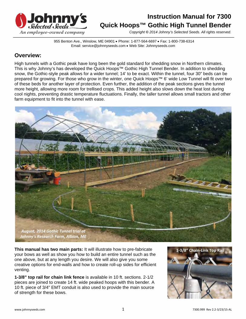
Overview: High tunnels with a Gothic peak have long been the gold standard for shedding snow in Northern climates. This is why Johnny’s has developed the Quick Hoops™ Gothic High Tunnel Bender. In addition to shedding snow, the Gothic-style peak allows for a wider tunnel; 14’ to be exact. Within the tunnel, four 30” beds can be prepared for growing. For those who grow in the winter, one Quick Hoops™ 6’ wide Low Tunnel will fit over two of these beds for another layer of protection. Even further, the addition of the peak sections gives the tunnel more height, allowing more room for trellised crops. This added height also slows down the heat lost during cool nights, preventing drastic temperature fluctuations. Finally, the taller tunnel allows small tractors and other farm equipment to fit into the tunnel with ease.
This manual has two main parts: It will illustrate how to pre-fabricate your bows as well as show you how to build an entire tunnel such as the one above, but at any length you desire. We will also give you some creative options for end-walls and how to create roll-up sides for efficient venting.
1-3/8” top rail for chain link fence is available in 10 ft. sections. 2-1/2pieces are joined to create 14 ft. wide peaked hoops with this bender. A10 ft. piece of 3/4" EMT conduit is also used to provide the main sourceof strength for these bows.
August, 2014 Gothic Tunnel trial at Johnny's Research Farm, Albion, ME
Instruction Manual for 7300Quick Hoops™ Gothic High Tunnel Bender
Copyright © 2014 Johnny’s Selected Seeds. All rights reserved.
1‐3/8” Chain‐Link Top Rail

www.johnnyseeds.com 2 7300.999 Rev 2.2‐3/23/15‐AL
Construction Options: We provide instructions on two main methods to build your tunnel:
Eliot Coleman is credited for the conception of this hoop design as he incorporated it into the plans for his modular moveable 'Cathedral' tunnel. His design criteria included requirements that the structure needed to span four 30" beds, could shed snow easily, and could be moved in any direction. In the Fall of 2013, the modular Cathedral tunnel was born. It was comprised of three 14' x 16' tunnel modules (the frame of one module is shown above left) that are connected with a 1' space between to create a 50' structure. His idea was that home gardeners could also build a single module for backyard use.
Johnny's has developed instructions using Eliot's hoop design, which we adapted to create traditional, fixed high tunnels. This includes the use of more traditional elements, such as driven ground posts, framed end-walls, hipboards, footboards, and roll-up side vents. This allows you to create a very solid, fixed structure with a relatively small investment.
Eliot's original plans called for creating the side-hoops of the bows with the 9018 Quick Hoops™ High Tunnel Bender and illustrated creating a jig to bend the 5 ft. peak section. Since then, Johnny's has developed the 7300 Quick Hoops™ Gothic High Tunnel Bender, which simplifies the process by including the 9018 Bender plus a special jig for the peak sections. If you already own a 9018 Bender, you can choose to buy just the 7300.100 Peak Jig instead of the complete 7300 High Tunnel Bender. Both the 7300 and the 7300.100 will include both sets of instructions so you can build either of these types of tunnels.
If you would like to build the Modular, Moveable 'Cathedral' tunnel, please refer to the other set of instructions. The remainder of this set of instructions is written for the Traditional, Fixed 'Gothic' style tunnel.
14' x 200' Gothic Tunnel at Johnny's Research Farm, Albion, ME
Modular, Moveable 'Cathedral' Tunnel Traditional, Fixed 'Gothic' Tunnel

www.johnnyseeds.com 3 7300.999 Rev 2.2‐3/23/15‐AL
Materials: This Excel spreadsheet calculator has been developed to allow you to custom design a tunnel to meet your own operational and financial needs. It may be downloaded from the product page for the 7300 Quick Hoops™ Gothic High Tunnel Bender or from the Growers Library on our website.
For your convenience, all part numbers listed on it link to product pages of their own on our website as well as other sources' websites.
Simply input the values in the different option boxes on the upper left and the spreadsheet will automatically tell you the following:
How many of each component you will need,
Suggest where you may purchase them,
Give you a square footage calculation,
Estimated total cost calculation,
And cost per square foot.
It will allow you to quickly see cost estimates for different tunnel options and allow you to quickly determine which ones meet your needs and your budget.

www.johnnyseeds.com 4 7300.999 Rev 2.2‐3/23/15‐AL
Contents for Part# 7300:
Curved bender and long lever bar (for “finishing” the bend) *
Peak Jig and (2) short lever bars
Hardware for mounting to wood surfaces: (4) 1/4" x 5" lag screws, (4) 1/4" x 6" carriage bolts, (4) 1/4" nuts, and (4) fender washers*
Detailed instructions for both types of tunnels - Modular, Moveable 'Cathedral' tunnel and the Traditional, Fixed 'Gothic' style tunnel
*Note: If you already have Johnny's 9018 High Tunnel Bender and have purchased part# 7300.100, everything above will be included except the curved bender long lever bar and exactly half of the mounting hardware.
Mounting the Peak Jig:
Both the curved bender and the Peak Jig may be mounted to any solid surface, such as a workbench, a picnic table, hay wagon, etc. They may be lag-screwed or thru-bolted into place. 5/16” mounting holes are provided on them and the screws, bolts, etc. to mount them are also included. By securing the bender and jig fixed positions, and pulling the tubing around them the operators can maintain precise control of the tubing being bent.
The curved bender, wherever mounted, must have enough room to accommodate the infeed and outfeed of pipe, as well as some type of support at the outfeed end about ¾” above the mounting surface. This will prevent ‘corkscrewing’ and ensure that the hoophouse bows created are in a single plane and not warped looking. This can best be accomplished with 3/4” plywood (shown above).
The Peak Jig should be mounted such that there are a couple inches between the pipe being bent and the edge of the mounting surface.
BBBeeennndddeeerrr
LLLeeevvveeerrr BBBaaarrr

www.johnnyseeds.com 5 7300.999 Rev 2.2‐3/23/15‐AL
Bending the Side Hoops:
1. After determining how many bows your high tunnel will have, set aside twice that many pipes to be bent.
2. Insert the swaged end of a pipe into the holding strap at the end of the bender. Insert just past the swage to prevent canting or kinking that portion of the pipe.
3. With a smooth motion, pull back as if on a long oar (do not push), and bend the pipe all the way around the bender until the pipe just touches the bender at the end closest to you. Stop. Do not bend past the end, or the arc you create will not be smooth.
4. Release tension until the pipe is loose in the holding strap and move it through the holding strap about half the length of the bender itself.
5. Repeat Steps 3. and 4. until about 3’ of unbent pipe remains beyond the closest end of the bender, or if bending becomes difficult.
6. Insert the lever bar into the female end of the pipe. This effectively makes the pipe longer and will instantly give you more leverage for bending the rest of the pipe.
7. Continue, repeating Steps 3. and 4. until you have bent all but 18” of the pipe. Keep this end straight. Doing so allows the bow to more easily fit into the ground posts.
8. Repeat Steps 2. through 7. for all other unbent pipes, always inserting the swaged end of the pipe into the bender holding strap first, until all pipes for the side hoops are bent.

www.johnnyseeds.com 6 7300.999 Rev 2.2‐3/23/15‐AL
Creating the Peak Sections:
1. Prefabrication:
a. From the calculator, determine the number of peak sections you will need for your tunnel. Set aside half as many pieces of 10’ top-rail.
b. Cut two 5’ sections from each piece of top-rail, excluding the swaged ends.
c. Pre-drill a 5/16” hole through the center of each piece to be used as a peak section. Only drill through one wall. This will prevent the opposite side from cracking when it is being bent.
d. De-burr any cut ends of the pipe as well as pre-drilled holes using a hand file, die grinder, or bench grinder. It may be necessary to ream out drilled holes after deburring by re-drilling.

www.johnnyseeds.com 7 7300.999 Rev 2.2‐3/23/15‐AL
2. Bending:
a. Place the first 5’ section of top-rail on the Quick Hoops™ Gothic High Tunnel Bender, inserting the 1/4" bolt on the bender into the pre-drilled hole in the center of the underside of the peak section. This will both center it and keep it from slipping.
b. With another person, insert a short lever bar into each end of the section of top-rail.
c. Together, push down on the end of the lever bars until each side of the peak section reaches the cross-bar on the bender.
d. Repeat Steps 2.a. through 2.c. for the remaining pieces of top-rail to create the rest of the peak sections.
e. Compare peak sections after bending to ensure they are of the same angle. Adjust as necessary.

www.johnnyseeds.com 8 7300.999 Rev 2.2‐3/23/15‐AL
Creating Collar Ties:
1. Collar Ties are made with 10 ft. lengths of ¾” EMT electrical conduit. These will be placed on every bow. Insert ¾-1” of one end inside a bench vise with the mark positioned as shown. Fully compress the vise. Remove and repeat for the opposite end. Ensure that the flattened areas face the same direction. The ends may alternately be flattened with a hammer.
2. With a 5/16” drill bit (cobalt bits work best), drill through the center of the flattened area on each tie.
3. 'Dog ear' one side of the flattened area by sawing one corner off on each side. Hand file or bench grind the edge to remove any burrs. It may be necessary to ream out the holes after deburring by re-drilling.
Creating Angle Braces:
1. Eight angle braces (four for each end of the tunnel) must be made from four pieces of 1-3/8" top rail. These pieces should be about 4 ft. long (exact length is not critical). Do this by cutting the swaged end off the top rail and then cutting it in half.
2. As with the collar ties, flatten the ends with a large bench vise or hammer; ensure that the flats face the same direction.
3. 'Dog ear' cut both corners off each end. See photo to right. Then, pre-drill each end with a 5/16" drill bit.
4. De-burr any cut ends of the pipe and pre-drilled holes using a hand file, die grinder, or bench grinder. It may be necessary to ream out the holes after deburring by re-drilling.
www.johnnyseeds.com 9 7300.999 Rev 2.2‐3/23/15‐AL
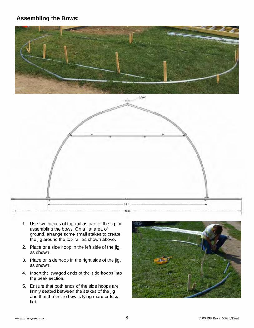
Assembling the Bows:
1. Use two pieces of top-rail as part of the jig for assembling the bows. On a flat area of ground, arrange some small stakes to create the jig around the top-rail as shown above.
2. Place one side hoop in the left side of the jig, as shown.
3. Place on side hoop in the right side of the jig, as shown.
4. Insert the swaged ends of the side hoops into the peak section.
5. Ensure that both ends of the side hoops are firmly seated between the stakes of the jig and that the entire bow is lying more or less flat.
www.johnnyseeds.com 10 7300.999 Rev 2.2‐3/23/15‐AL
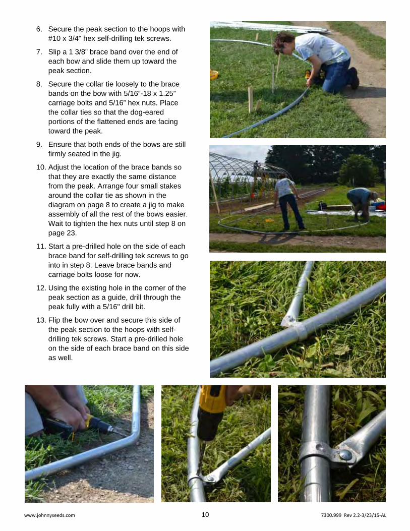
6. Secure the peak section to the hoops with #10 x 3/4" hex self-drilling tek screws.
7. Slip a 1 3/8” brace band over the end of each bow and slide them up toward the peak section.
8. Secure the collar tie loosely to the brace bands on the bow with 5/16”-18 x 1.25” carriage bolts and 5/16” hex nuts. Place the collar ties so that the dog-eared portions of the flattened ends are facing toward the peak.
9. Ensure that both ends of the bows are still firmly seated in the jig.
10. Adjust the location of the brace bands so that they are exactly the same distance from the peak. Arrange four small stakes around the collar tie as shown in the diagram on page 8 to create a jig to make assembly of all the rest of the bows easier. Wait to tighten the hex nuts until step 8 on page 23.
11. Start a pre-drilled hole on the side of each brace band for self-drilling tek screws to go into in step 8. Leave brace bands and carriage bolts loose for now.
12. Using the existing hole in the corner of the peak section as a guide, drill through the peak fully with a 5/16" drill bit.
13. Flip the bow over and secure this side of the peak section to the hoops with self-drilling tek screws. Start a pre-drilled hole on the side of each brace band on this side as well.
www.johnnyseeds.com 11 7300.999 Rev 2.2‐3/23/15‐AL
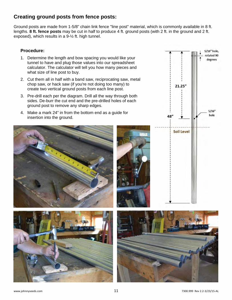
Creating ground posts from fence posts:
Ground posts are made from 1-5/8” chain link fence "line post" material, which is commonly available in 8 ft. lengths. 8 ft. fence posts may be cut in half to produce 4 ft. ground posts (with 2 ft. in the ground and 2 ft. exposed), which results in a 9-½ ft. high tunnel.
Procedure:
1. Determine the length and bow spacing you would like your tunnel to have and plug those values into our spreadsheet calculator. The calculator will tell you how many pieces and what size of line post to buy.
2. Cut them all in half with a band saw, reciprocating saw, metal chop saw, or hack saw (if you're not doing too many) to create two vertical ground posts from each line post.
3. Pre-drill each per the diagram. Drill all the way through both sides. De-burr the cut end and the pre-drilled holes of each ground post to remove any sharp edges.
4. Make a mark 24” in from the bottom end as a guide for insertion into the ground.

www.johnnyseeds.com 12 7300.999 Rev 2.2‐3/23/15‐AL
Hints on setting the corner ground posts: Use the following diagrams to help you set the corner posts in a perfect rectangle.
A B
A > B
Tunnel is
crooked.
A B
A = B
Tunnel is
squared off.
3. Measure out from
C2 the desired
tunnel length.
12 ft.
4. Lay the notched end
of the gauge at that
measurement spot.
1. Set the first
corner post C1.
2. Using the gauge, set the
second corner post C2.
7. Take measurements A and B above.
8. Adjust the gauge to the right
or left until A and B are equal. 9. Set corner posts C3 and C4.
C1 C2
C4 C3
C1 C2 C1 C2
Start here.
5. Measure out from
C1 the desired
tunnel length.
6. Adjust the un‐notched
end of the gauge to that
measurement spot.
Tunnel forms
a perfect
rectangle.
C1 C2

www.johnnyseeds.com 13 7300.999 Rev 2.2‐3/23/15‐AL
Site preparation and setting the ground posts:
1. Prepare the footprint of the tunnel as if you would open soil in a field.
2. Create a gauge for setting posts by using one 5/4" x 6” x 14’ piece of wood, and simply cutting a small notch in one end. This will be the gauge between ground posts for a single bow. You can also simply use a tape measure in lieu of a gauge.
3. Weed Barrier - An option to consider at this point is weed barrier along the edges of the tunnel. This is traditionally an area where weed control is difficult and some fabric that suppresses weeds can be very effective here. If you choose this option, proceed to step 5.
4. If you choose to forgo weed barrier, proceed as follows: Set the four corner ground posts first as follows:
a. Place the first corner post (#1 pictured above) in the desired location with the pre-drilled hole closest to the top. Insert the mushroom-shaped ground post driver in the top and drive it in about 2 ft. with a sledge-hammer until the mark is at the soil surface.
b. Place the notched end of the 14 ft. gauge you made in Step 2 against post 1. Swing the opposite end the gauge to where you would like post 2 to be. Holding the new ground post against the un-notched end, drive it in place.
c. Using a long tape, measure to where the opposite end of the tunnel will be. Mark approximately where you expect to put post 3.
d. Lay the notched end of the gauge down at that spot. Lay the opposite end where your think post 4 will be. Measure from post 1 to the notch in the 14 ft gauge. Then measure from post 2 to the un-notched end of the gauge. These measurements should be the same for the tunnel to be square and true. Adjust the gauge until they are.
e. Set corner posts 3 and 4.
f. Run the long tape from corner post 1 to corner post 4. Secure one end to post 1. Pull it tight and secure the other end to post 4. Secure with duct tape, clamps, or something similar. This will serve as a gauge as well as a straight line for setting the other posts.
1
2
3 4

www.johnnyseeds.com 14 7300.999 Rev 2.2‐3/23/15‐AL
g. Using the long tape measure as a guide, set the rest of the posts for this side of the tunnel.
h. Repeat steps 4.f. and g. for the other side of the tunnel.
i. Inspect the orientation of ground posts and adjust as necessary: Pre-drilled bolt holes (near the ground) should be facing outward from the tunnel to minimize adjustment later on. Bolt holes for the bolts that hold the bows in place (near the top of the ground posts) should be in line with the length of the tunnel. By hand or (if necessary) with a pipe wrench or similar tool, rotate any ground posts as needed so that they are correctly oriented.
j. The ground posts are now set and ready for bows.
JSS #9482 Ground Post Driver

www.johnnyseeds.com 15 7300.999 Rev 2.2‐3/23/15‐AL
5. If you do choose to use weed barrier, proceed as follows:
a. Perform steps 4.a. through e. to set and square the four corner posts.
b. If you have a pair of D-handle garden forks or spades, you can quickly set up your weed barrier on a makeshift spool such as this. This makes handling and cutting to length very easy. A piece of top-rail is used as the spindle. Position at one end of the tunnel location and offset, so that it faces down the side of what will eventually be the tunnel. Pull a few inches of the weed barrier off the roll, and with a utility knife, cut it down the center so that you have started two 2 ft. wide strips. Have one person hold the utility knife near the roll with the blade through the fabric, while one or two others pull the fabric off the roll and walk with it down the side of the plot until you reach the opposite end. Cut it to length, leaving about 1 ft. of overlap on each end. A yellow centerline mark should be conveniently placed at or near the centerline of each of the two 2 ft wide strips. Position each 14 ft. apart on center and parallel.
c. Make a 2" cut centered between the sides of the fabric that is about 1 ft. in from one cut end. Make just a single cut in line with the length of the fabric. Slip this end of the fabric over the end post near it.
With only a single slit, the fabric will be somewhat snug against the post, which helps prevent weeds from growing up through the hole.
9739 Weed Barrier. 4' x 50' 9724 Weed Barrier. 4' x 250'
A note about weed barrier - Keep the top of the weed barrier fabric free of soil as best you can. If soil is allowed to collect on it, weeds will likely germinate in that soil and root through the weed barrier, which will make them difficult to kill and remove by physical means.
d. Go to the opposite end of the fabric, pull it straight and somewhat taught, and make a similar cut that is even with the corner ground post at that end. Slip it over the ground post and smooth out the weed barrier along the length of the tunnel.
e. Secure the edges of the weed barrier to the ground with fabric staples along its edges. A hammer is sometimes helpful in difficult soils. 9723 Fabric Staples. Box of 500.
f. Repeat steps 5.b through f. for the opposite side of the tunnel.

www.johnnyseeds.com 16 7300.999 Rev 2.2‐3/23/15‐AL
g. Run a long tape measure down the center of one of the pieces of weed barrier fabric and secure to the corner posts with clamps, etc.
h. Make 2" slits with a razor knife for the rest of the ground posts on that side of the tunnel. For example, make a cut every 4 ft. if your tunnel will have 4 ft. bow spacing.
i. Drive ground posts in each of the slits.
j. Repeat 5.h. and i. for the opposite side of the tunnel until all the ground posts are set.
k. Perform step 4.i. to align the ground posts.

www.johnnyseeds.com 17 7300.999 Rev 2.2‐3/23/15‐AL
Framing the Tunnel:
1. Bows: make a mark on each of the bows about 6” from the end. This will be used as a guide for insertion into the ground posts.
a. Clamp large vise grips or spring clamps onto each side of the bow just above the marks to keep it from slipping into the ground posts.
b. Transport the first “end wall” bow to the furthest corner posts and insert to the marks made in step 1. above.
c. Using the upper pre-drilled holes in the ground posts as a guide, with a 5/16" drill bit, drill through the inserted portion of each side of the bow. These should be aligned such that they are in line with the length of the tunnel.
d. Secure the bow to the ground post with 5/16"-18 x 2" hex bolts and 5/16" hex nuts.
e. Repeat steps 1.a. through 1.d. for the rest of the bows.

www.johnnyseeds.com 18 7300.999 Rev 2.2‐3/23/15‐AL
2. Ridge Pole: pre-drill a 5/16" hole through the non-swaged end of a piece of 1-3/8" top rail for chain link fence at about 9/16" from the end. Drill through both walls. This will serve as the first piece of ridge pole. Note: if you intend to install scissor doors on this end of the tunnel, you will need about 4" of ridge pole protruding over the end of the tunnel; in that case, drill the hole 4-9/16" from the end of the top-rail.
a. Raise the top-rail up to one of the end wall bows of the tunnel and place the hole directly over the hole in the center of the peak connector. The rest of the ridge pole should be roughly aligned with the peak of the next bow and temporarily held or clamped in place. With a 5/16" drill bit, ream through both the peak connector and the ridge pole so that they can easily accept a through bolt.
b. Fasten the end of the ridge pole to the end wall bow with a 5/16"-18 x 3" carriage bolt inserted from the top and secured at the bottom with a flat washer and 5/16" hex nut.
c. Attach the end of a long tape measure to the end of the ridge pole with a clamp or tape and run the tape to the opposite end of the tunnel.
d. Adjust the position of the peak of the next bow so that it is 4 ft. from the previous bow. Using the hole in the peak connector as a guide, drill up through both walls of the ridge pole. You may find it easier to drill down from the top; that works fine, but remember to ream through the ridge pole and the peak connector after so that a bolt may be easily inserted through both the ridge pole and peak connector. As before, secure the ridge pole to the bow with a 5/16"-18 x 3" carriage bolt, flat washer, and 5/16" hex nut.
e. Slide the non-swaged end of another piece of top-rail over the swaged end of the ridge pole. Secure together from beneath with a #10 x 3/4" hex-head self-drilling tek screw.
f. Repeat step 2.d. for the third bow (only).

www.johnnyseeds.com 19 7300.999 Rev 2.2‐3/23/15‐AL
3. Angle Ties: at this point, angle ties must be installed so that all successive bows are vertical and plumb. Slip a 1-3/8" brace band over one of the side hoops of one of the end wall bows, two 1-3/8" brace bands over the next bow, and one 1-5/8" brace band over the third ground post.
a. Position the 1-5/8" brace band on the third hoop's ground post at ground level, with its tabs pointing toward the closest end of the tunnel, compress them with a pair of needle nose Vise Grips. Loosely secure one end of an angle tie to the brace band with a 5/16"-18 x 1.25" carriage bolt and 5/16" nut. Remove the Vise Grips.
b. Raise the opposite end of the angle tie up and rest it against the next bow. Slide both 1-3/8" brace bands up the second bow's side hoop until the lower brace band is aligned to receive the end of the angle tie. Clamp in place with the Vise Grips. Loosely secure with a 5/16"-18 x 1.25" carriage bolt and 5/16" nut. Remove the Vise Grips.
c. Position the second brace band on the second bow so that it is resting on the previously attached brace band and pointing toward the closest end of the tunnel. Clamp with the Vise Grips and loosely secure with a 5/16"-18 x 1.25" carriage bolt and 5/16" nut. Remove the Vise Grips.
d. Raise the opposite end of the angle tie up and rest it against the end wall bow. Slide the 1-3/8" brace band up the end wall side hoop until the brace band is aligned to receive the end of the angle tie. Clamp in place with the Vise Grips. Loosely secure with a 5/16"-18 x 1.25" carriage bolt and 5/16" nut. Remove the Vise Grips.
e. Using a plumb bob or long level, adjust the end wall bow so that it is plumb (vertically level). All three bows should move together. While holding the end wall in that position, quickly tighten all the nuts on the angle ties' brace bands.
f. Repeat steps 3.a. through 3.e. for the opposite side of the tunnel.
g. Secure all brace bands installed in steps 14. through 20. from inside the tunnel with #10 x 3/4" hex self-drilling tek screws by screwing through the side of the brace band and into the bow or ground post. This will prevent any slippage later on.
www.johnnyseeds.com 20 7300.999 Rev 2.2‐3/23/15‐AL
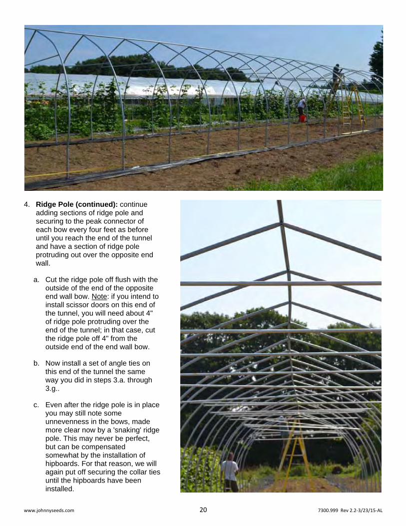
4. Ridge Pole (continued): continue adding sections of ridge pole and securing to the peak connector of each bow every four feet as before until you reach the end of the tunnel and have a section of ridge pole protruding out over the opposite end wall.
a. Cut the ridge pole off flush with the outside of the end of the opposite end wall bow. Note: if you intend to install scissor doors on this end of the tunnel, you will need about 4" of ridge pole protruding over the end of the tunnel; in that case, cut the ridge pole off 4" from the outside end of the end wall bow.
b. Now install a set of angle ties on this end of the tunnel the same way you did in steps 3.a. through 3.g..
c. Even after the ridge pole is in place you may still note some unnevenness in the bows, made more clear now by a 'snaking' ridge pole. This may never be perfect, but can be compensated somewhat by the installation of hipboards. For that reason, we will again put off securing the collar ties until the hipboards have been installed.
www.johnnyseeds.com 21 7300.999 Rev 2.2‐3/23/15‐AL
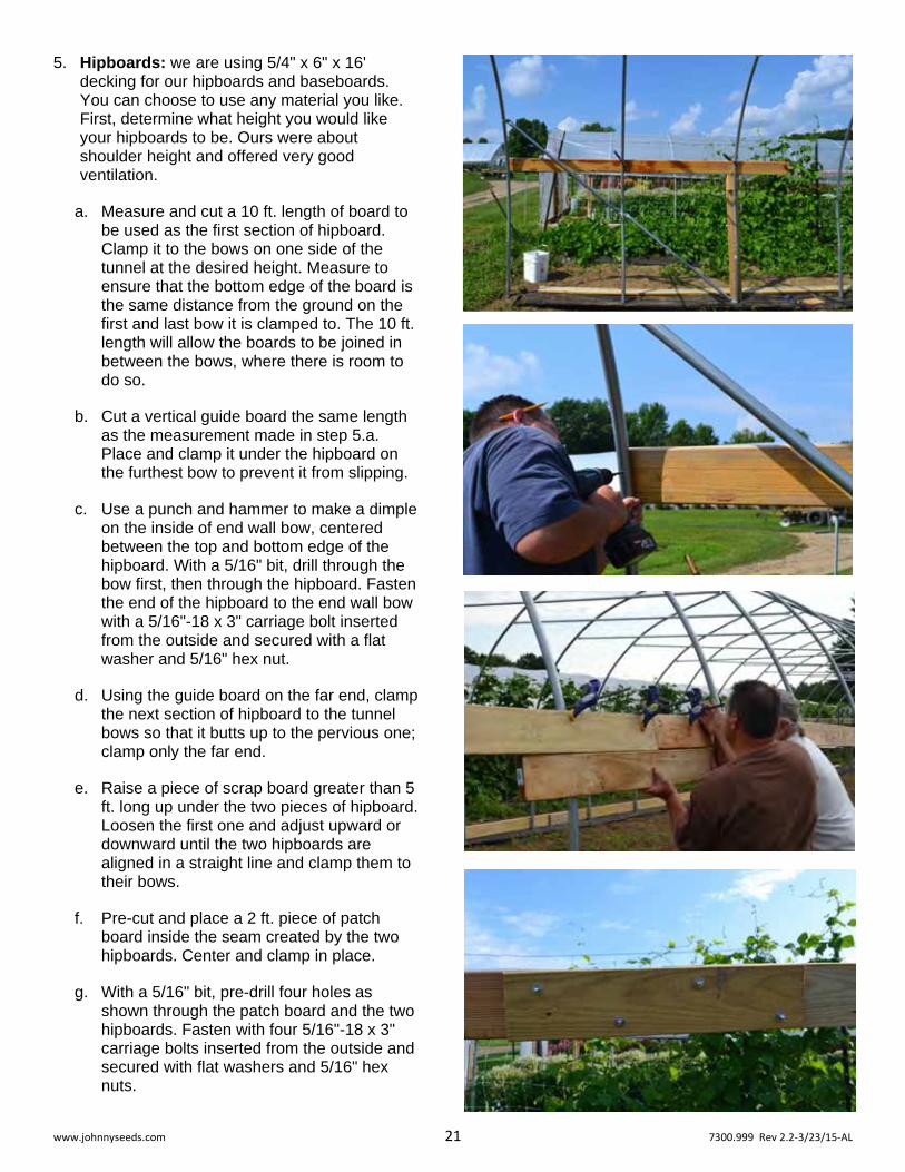
5. Hipboards: we are using 5/4" x 6" x 16' decking for our hipboards and baseboards. You can choose to use any material you like. First, determine what height you would like your hipboards to be. Ours were about shoulder height and offered very good ventilation.
a. Measure and cut a 10 ft. length of board to be used as the first section of hipboard. Clamp it to the bows on one side of the tunnel at the desired height. Measure to ensure that the bottom edge of the board is the same distance from the ground on the first and last bow it is clamped to. The 10 ft. length will allow the boards to be joined in between the bows, where there is room to do so.
b. Cut a vertical guide board the same length as the measurement made in step 5.a. Place and clamp it under the hipboard on the furthest bow to prevent it from slipping.
c. Use a punch and hammer to make a dimple on the inside of end wall bow, centered between the top and bottom edge of the hipboard. With a 5/16" bit, drill through the bow first, then through the hipboard. Fasten the end of the hipboard to the end wall bow with a 5/16"-18 x 3" carriage bolt inserted from the outside and secured with a flat washer and 5/16" hex nut.
d. Using the guide board on the far end, clamp the next section of hipboard to the tunnel bows so that it butts up to the pervious one; clamp only the far end.
e. Raise a piece of scrap board greater than 5 ft. long up under the two pieces of hipboard. Loosen the first one and adjust upward or downward until the two hipboards are aligned in a straight line and clamp them to their bows.
f. Pre-cut and place a 2 ft. piece of patch board inside the seam created by the two hipboards. Center and clamp in place.
g. With a 5/16" bit, pre-drill four holes as shown through the patch board and the two hipboards. Fasten with four 5/16"-18 x 3" carriage bolts inserted from the outside and secured with flat washers and 5/16" hex nuts.

www.johnnyseeds.com 22 7300.999 Rev 2.2‐3/23/15‐AL
h. Repeat step 5.c. for each of the remaining bows the first hipboard is attached to, as well as the first bow the second hipboard is attached to.
i. Continue on down the tunnel, repeating steps 5.c. through 5.h.. until the last hipboard is in place and a section of hipboard is protruding outward past the opposite end wall.
j. Cut the hipboard off flush with the outside of the end of the opposite end wall bow.
k. Repeat steps 5.a. and 5.c. through 5.j. for the opposite side of the tunnel.
6. Baseboards: these are installed the same way as the hipboards except for the fasteners used to secure them and the need to align them, since they lay flat against the ground.
a. Measure and cut a 10 ft. length of board to be used as the first section of baseboard. Clamp it to the ground posts on one side of the tunnel. Similar to the first hipboard, this 10 ft. length will allow the baseboards to be joined in between the bows, where there is room to do so.
b. Using the lower pre-drilled holes in the ground posts as a guide, with a 5/16" drill bit, drill through the ground post first, then through the baseboard. Fasten the end of the baseboard to the end wall ground post with a 5/16"-18 x 7" J- bolt inserted from the outside and secured with a flat washer and two 5/16" hex nuts.
c. Clamp the next section of baseboard to the tunnel ground posts so that it butts up to previous one.
d. Pre-cut and place a 2 ft. piece of patch board inside the seam created by the two baseboards. Center and clamp in place.
e. With a 5/16" bit, pre-drill two holes as shown through the patch board and the two baseboards. Fasten with two 5/16"-18 x 3" carriage bolts inserted from the outside and secured with flat washers and 5/16" hex nuts.

www.johnnyseeds.com 23 7300.999 Rev 2.2‐3/23/15‐AL
f. Repeat step 6.b. for each of the remaining ground posts the baseboards are attached to.
g. Continue down the tunnel, repeating steps 6.c. through 6.e. until the last baseboard is in place and asection of basboard is protruding outward past the opposite end wall. Before attaching, cut the lastbaseboard to length so that it is flush with the outsideof the end of the opposite end wall ground post.
h. Repeat steps 6.a. through 6.g. for the opposite side ofthe tunnel.
7. Poly Latch Wire Channel on the Hipboards and Baseboards: Poly Latch Wire is used to hold the main covering in place and secure it along the length and above the roll up sides.
a. Using #10 x 3/4" phillips self-drilling tek screws about every 12", secure Poly Latch Wire Channel down the middle of the outside of the hipboard. Cut off any excess on the opposite end flush to the end of the hipboard.
b. Cut to length and secure a 4 ft. section at each end, on each side of the tunnel laying on top of the baseboards. Secure it to the end wall bow and the next bow in. This will serve to hold an overlap panel of plastic to prevent drafts and heat loss at the ends of the roll up sides.
c. Using clamps, form and attach and piece of Poly Latch Wire Channel to the second bow in between the channel attached in step 42. and the bottom of the hipboard.
www.johnnyseeds.com 24 7300.999 Rev 2.2‐3/23/15‐AL
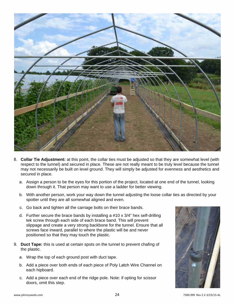
8. Collar Tie Adjustment: at this point, the collar ties must be adjusted so that they are somewhat level (with respect to the tunnel) and secured in place. These are not really meant to be truly level because the tunnel may not necessarily be built on level ground. They will simply be adjusted for evenness and aesthetics and secured in place.
a. Assign a person to be the eyes for this portion of the project, located at one end of the tunnel, looking down through it. That person may want to use a ladder for better viewing.
b. With another person, work your way down the tunnel adjusting the loose collar ties as directed by your spotter until they are all somewhat aligned and even.
c. Go back and tighten all the carriage bolts on their brace bands.
d. Further secure the brace bands by installing a #10 x 3/4" hex self-drillingtek screw through each side of each brace band. This will preventslippage and create a very strong backbone for the tunnel. Ensure that allscrews face inward, parallel to where the plastic will be and neverpositioned so that they may touch the plastic.
9. Duct Tape: this is used at certain spots on the tunnel to prevent chafing ofthe plastic.
a. Wrap the top of each ground post with duct tape.
b. Add a piece over both ends of each piece of Poly Latch Wire Channel oneach hipboard.
c. Add a piece over each end of the ridge pole. Note: if opting for scissordoors, omit this step.
www.johnnyseeds.com 25 7300.999 Rev 2.2‐3/23/15‐AL
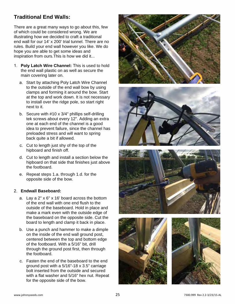
Traditional End Walls:
There are a great many ways to go about this, few of which could be considered wrong. We are illustrating how we decided to craft a traditional end wall for our 14' x 200' trial tunnel. There are no rules. Build your end wall however you like. We do hope you are able to get some ideas and inspiration from ours.This is how we did it...
1. Poly Latch Wire Channel: This is used to hold the end wall plastic on as well as secure the main covering later on.
a. Start by attaching Poly Latch Wire Channel to the outside of the end wall bow by using clamps and forming it around the bow. Start at the top and work down. It is not necessary to install over the ridge pole, so start right next to it.
b. Secure with #10 x 3/4" phillips self-drilling tek screws about every 12". Adding an extra one at each end of the channel is a good idea to prevent failure, since the channel has preloaded stress and will want to spring back quite a bit if allowed.
c. Cut to length just shy of the top of the hipboard and finish off.
d. Cut to length and install a section below the hipboard on that side that finishes just above the footboard.
e. Repeat steps 1.a. through 1.d. for the opposite side of the bow.
2. Endwall Baseboard:
a. Lay a 2" x 6" x 16' board across the bottom of the end wall with one end flush to the outside of the baseboard. Hold in place and make a mark even with the outside edge of the baseboard on the opposite side. Cut the board to length and clamp it back in place.
b. Use a punch and hammer to make a dimple on the inside of the end wall ground post, centered between the top and bottom edge of the footboard. With a 5/16" bit, drill through the ground post first, then through the footboard.
c. Fasten the end of the baseboard to the end ground post with a 5/16"-18 x 3.5" carriage bolt inserted from the outside and secured with a flat washer and 5/16" hex nut. Repeat for the opposite side of the bow.

www.johnnyseeds.com 26 7300.999 Rev 2.2‐3/23/15‐AL
3. Door Frame:
a. Measure across the endwall baseboard, find center and mark it on the baseboard.
b. Make a mark on the baseboard 32" to the right and 32" to the left of the center mark. These will be the door frame's bottom inside boundaries.
c. Raise a 2" x 4" x 10' board vertically up to the middle of the end wall and align one edge of it with the center of the ridge pole and the first mark made in 3.a. above. Make a mark on the collar tie that along that edge of the board. Make a mark on the collar tie 32" to the right and 32" to the left of that mark. This will be the door frame's upper inside boundaries.
d. Now, with its end resting on the ground inside the end wall and its narrow side against the baseboard and endwall bow, align the inside edge of the 2" x 4" x 10' board with left-most marks on the collar tie and base board. Clamp in place or have a helper hold the board. Make marks just above the baseboard, above and below the collar tie, and above and below the bow.
e. Finish making marks using a hand square per the top board in the diagram above. Note that the measurements in the diagram are approximate as your marks may vary somewhat from them. Notch these out 1.5" deep and cut to length so the board will be flush with the bow.
www.johnnyseeds.com 27 7300.999 Rev 2.2‐3/23/15‐AL
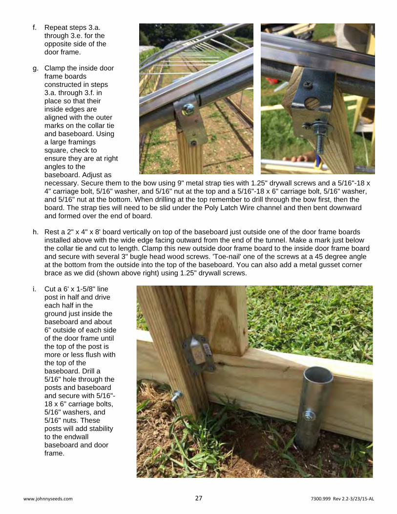
f. Repeat steps 3.a.through 3.e. for theopposite side of thedoor frame.
g. Clamp the inside doorframe boardsconstructed in steps3.a. through 3.f. inplace so that theirinside edges arealigned with the outermarks on the collar tieand baseboard. Usinga large framingssquare, check toensure they are at rightangles to thebaseboard. Adjust asnecessary. Secure them to the bow using 9" metal strap ties with 1.25" drywall screws and a 5/16"-18 x 4" carriage bolt, 5/16" washer, and 5/16" nut at the top and a 5/16"-18 x 6" carriage bolt, 5/16" washer, and 5/16" nut at the bottom. When drilling at the top remember to drill through the bow first, then the board. The strap ties will need to be slid under the Poly Latch Wire channel and then bent downward and formed over the end of board.
h. Rest a 2" x 4" x 8' board vertically on top of the baseboard just outside one of the door frame boards installed above with the wide edge facing outward from the end of the tunnel. Make a mark just below the collar tie and cut to length. Clamp this new outside door frame board to the inside door frame board and secure with several 3" bugle head wood screws. 'Toe-nail' one of the screws at a 45 degree angle at the bottom from the outside into the top of the baseboard. You can also add a metal gusset corner brace as we did (shown above right) using 1.25" drywall screws.
i. Cut a 6' x 1-5/8" linepost in half and driveeach half in theground just inside thebaseboard and about6" outside of each sideof the door frame untilthe top of the post ismore or less flush withthe top of thebaseboard. Drill a5/16" hole through theposts and baseboardand secure with 5/16"-18 x 6" carriage bolts,5/16" washers, and5/16" nuts. Theseposts will add stabilityto the endwallbaseboard and doorframe.

www.johnnyseeds.com 28 7300.999 Rev 2.2‐3/23/15‐AL
j. Cut two more pieces of 2" x 4" to a length of 64". Place one at the top of the door opening so that the wide edge is facing the end of the tunnel. Secure at each end with a couple 3" bugle head wood screws. Place the second one under the first with its narrow edge facing out and flus with the outside edges of the door frame. Secure at each end with a couple 3" bugle head wood screws, then secure the second board to the first with four more 3" bugle head wood screws.
k. Pre-drill a 5/16" hole in the center of a deck framing bracket and secure inside the bow, centered on the hipboard, with self-drilling tek screws and the existing carriage bolt. At an even height from the baseboard, attach another bracket to the outside edge of the door frame, using 1.25" drywall screws. Cut a 2" x 4" board to fit, notching the angled end for the carriage bolt. install and secure with 1.25" drywall screws. Repeat for the opposite side.

www.johnnyseeds.com 29 7300.999 Rev 2.2‐3/23/15‐AL
4. Doors: these will be built in-place for best fit. The measurements below are approximate, since the boards will be cut to fit. See diagram on the following page for the sequence used for assembly.
a. Lay some type of spacer that is about a 1/4" thick on top of the baseboard inside the door frame (we used a piece of angle iron). Hold a 2" x 4" board vertically in the door opening and mark on the board about a 1/4" below the lower edge of the top of the door frame. Cut to length. Return the board to the same spot on top of the spacer and check for fit. There should be about a 1/4" space above the door. If the fit is tight, trim as necessary, then cut three more the same length. These should be about 82" long, but may be slightly different for your tunnel. Place board #1 snug to the left side of the door frame and clamp in place.
b. Place board #2 about 1/8" to the left of the center of the door frame on top of the spacer. Check for square with respect to the baseboard using a large framing square and clamp in place.
c. Hold a 2" x 4" board horizontally so it butts up to the first board and passes by the front face of the second. From inside the door, use board #2 as a straight-edge to mark the board. Cut the board off along that mark and check for fit. Trim as necessary and clamp board #3 in place at the bottom of the doorway between boards #1 and #2. This board should be about 24.5" long, but may be slightly different for your tunnel.
d. Repeat step 4.c. for board #4 at the top of the door.
e. Using 1.25" drywall screws, install flat metal L-straps at all four corners on the inside face of the door.
www.johnnyseeds.com 30 7300.999 Rev 2.2‐3/23/15‐AL
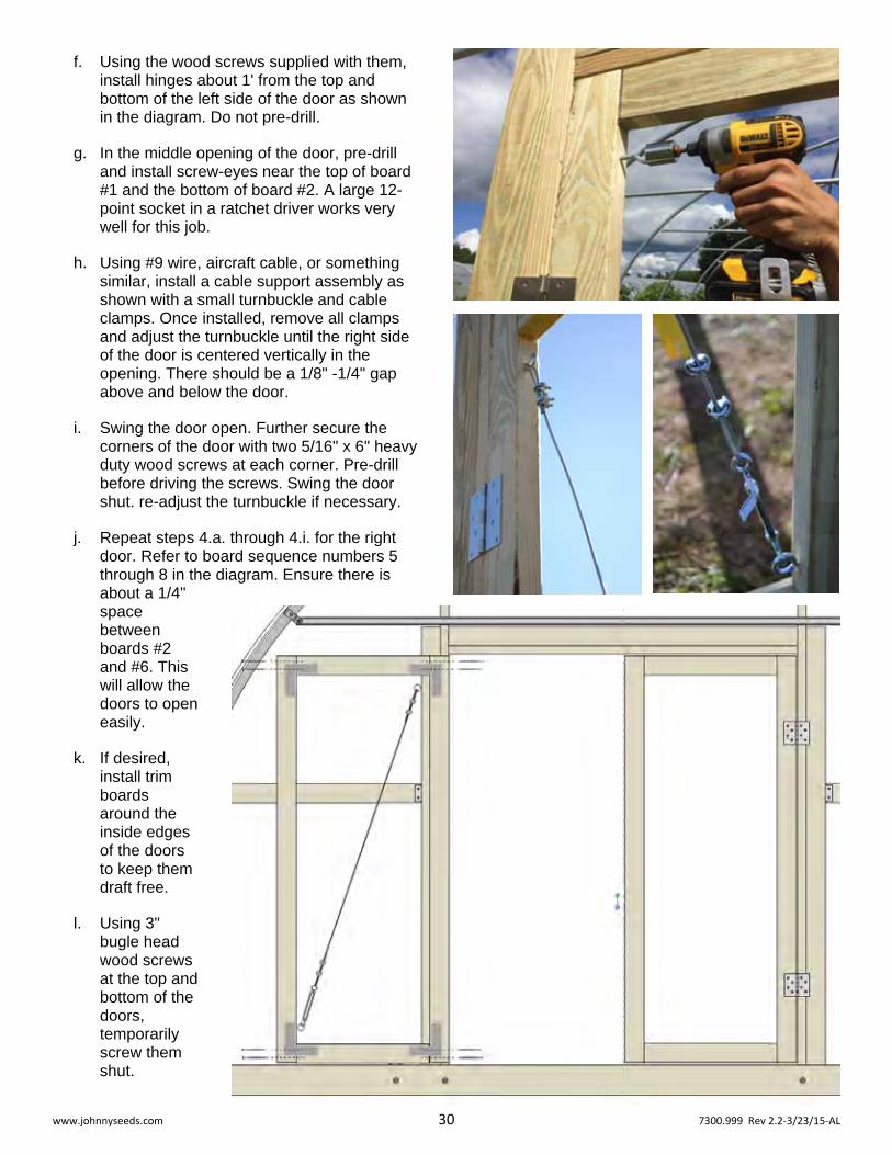
f. Using the wood screws supplied with them, install hinges about 1' from the top and bottom of the left side of the door as shown in the diagram. Do not pre-drill.
g. In the middle opening of the door, pre-drill and install screw-eyes near the top of board #1 and the bottom of board #2. A large 12-point socket in a ratchet driver works very well for this job.
h. Using #9 wire, aircraft cable, or something similar, install a cable support assembly as shown with a small turnbuckle and cable clamps. Once installed, remove all clamps and adjust the turnbuckle until the right side of the door is centered vertically in the opening. There should be a 1/8" -1/4" gap above and below the door.
i. Swing the door open. Further secure the corners of the door with two 5/16" x 6" heavy duty wood screws at each corner. Pre-drill before driving the screws. Swing the door shut. re-adjust the turnbuckle if necessary.
j. Repeat steps 4.a. through 4.i. for the right door. Refer to board sequence numbers 5 through 8 in the diagram. Ensure there is about a 1/4" space between boards #2 and #6. This will allow the doors to open easily.
k. If desired, install trim boards around the inside edges of the doors to keep them draft free.
l. Using 3" bugle head wood screws at the top and bottom of the doors, temporarily screw them shut.

www.johnnyseeds.com 31 7300.999 Rev 2.2‐3/23/15‐AL
m. Cut two 1" x 4" to span the insides of each of the doors as a bit of extra bracing. Level these with another piece of board as shown to the right.
n. Cut to length as needed an install Poly Latch Wire Channel around the open holes in the doors, around the door frame, and along both sides of the endwall baseboard.
5. Skinning the Endwall:
a. The plastic should be a 32'-wide 6 mil greenhouse film, that is at least 25 ft. longer than the tunnel will be. Cut a piece off the roll that is 12' long.
b. Lay the cut panel of plastic over the endwall so that one of the long edges (preferably the factory cut end) is along the ground and all edges of the endwall are overlapped with extra plastic. There may be manufacturer's writing on the plastic. You can use that as an aid to level the plastic across the endwall.
c. Starting at the top and working concurrently down both sides of the endwall bow, Poly Latch ("wiggle") wire the plastic into the channel, keeping the plastic taut across the face of the endwall as you go. Continue down to the baseboards.

www.johnnyseeds.com 32 7300.999 Rev 2.2‐3/23/15‐AL
d. Fold the excess side plastic around the endwall bow and over the area between the first and second bows, below the hipboard. Poly Latch wire the plastic tightly into this area. This will serve as an overlap panel to prevent drafts caused by the roll-up sides. Repeat for the opposite side of the tunnel.
e. Poly Latch wire the plastic into the channel on the endwall baseboard.
f. Poly Latch wire the plastic into the channel around the top and sides of the door frame.
g. Poly Latch wire the plastic into thechannel around each of the doors. At this point, much of the slack plastic has been taken up by the channel and may be very taught. You may need to cut the plastic between the channel on the doors and the channel on the frame to relieve the tension enough to install the Poly Latch wire. Be sure to pull it tight when installing the wire.

www.johnnyseeds.com 33 7300.999 Rev 2.2‐3/23/15‐AL
h. Trim off excess plastic along the outside edges of all the Poly Latch wire channel, leaving about an inch or so excess.
i. When you are done, the endwall should look like this:
6. Door hardware can beanything you dream up.
a. First, we installed a slidingbolt at the top and bottom ofthe left hand door, which willbe closed most of the time,but can be opened whenneeded to allow access forwalking tractors,wheelbarrows, and othersmall equipment.
b. Then, we created a jackpotlever latch that can beoperated from both theinside and outside of thetunnel. The latch wasdesigned with a bent 3/8"threaded rod, two small toolhandles, locknuts, washers,a wooden shim, and flatbracket over the shim toprevent wear and serve asa latch plate. The shimmedlatch plate serves to keepthe door tightly shut. Weadded a couple phillips self-drilling tek screws to serveas speed bumps to helpkeep the latch in place. Ifyou would like to create asimilar latch, the partnumber for the replacementhandles is 9673.500.

www.johnnyseeds.com 34 7300.999 Rev 2.2‐3/23/15‐AL
Scissor Doors for an End Wall:
This is another way to do an end wall that has been developed by Eliot Coleman and is in use extensively at his Four Season Farm. It is a very low cost method, but the beauty of it, especially for a tunnel this size or larger, is that it instantly allows small tractor access, which can be a huge labor saver. We installed scissor doors on just one end of our trial tunnel. This is how we did it...
1. Endwall Baseboard: this design has a baseboard the same size as the traditional endwall, but it is detachable.
a. Lay a 2" x 6" x 16' board across the bottom of the end wall with one end flush to the outside of the baseboard. Hold it in place and make a mark on the board even with the outside edge of the baseboard on the opposite side. Cut the board to length and clamp it back in place.
b. Use a punch and hammer to make a dimple on the inside of the end wall ground post centered between the top and bottom edge of the footboard. With a 3/8" bit, drill through the ground post first, then through the baseboard. Repeat for the opposite side of the bow.
c. Insert a 3/8" x 5" fully-threaded hex bolt through the hole with the threads facing outward. Secure to the ground post with a 3/8" hex jam nut and 3/8" lock washer. Repeat for the opposite side of the endwall bow.
d. Slide the removable baseboard onto the bolts installed in step 1.c.. Secure with 3/8" wing nuts and 3/8" flat washers.
e. Measure the width of the baseboard and make a mark at the center.
2. Scissor Rails:
a. Pre-drill a 5/16" hole through both walls 3/4" from the non-swaged end of two pieces of 1-3/8" top rail.
b. Position a brace band inside the predrilled end of one of the scissor door rails. Slide a 5/16"-18 x 1.75" carriage bolt through the predrilled holes and the brace band. Secure with a flat washer and 5/16" nut. Repeat for the other rail.
c. In step 4.a. of the Framing procedure, you should have opted to leave four extra inches of ridge pole protruding out from the endwall. If you did not, follow this procedure:
i. Cut the swaged end of a scrap piece of top-rail, so that the non-swaged portion is 4" long.
ii. Remove the ridge pole bolt on the endwall bow and insert the swaged end of the piece of scrap into the end of the ridge pole.
iii. Using the existing bolt holes as a guide, drill a 5/16" hole through both walls of the scrap piece and ream down through the hole in the peak of the bow.
iv. Insert the bolt through the ridge pole, scrap piece, and bow peak and secure with a flat washer and 5/16" nut.

www.johnnyseeds.com 35 7300.999 Rev 2.2‐3/23/15‐AL
d. Slide the brace band on the end of one of the rails over the ridge pole protruding over the end-wall. Add the second rail in the same fashion. They should hang freely and be able to rotate out to the sides of the tunnel easily. They should also just touch the ground or come close to it. If they are too long and hit the ground, cut them short as needed.
e. Drive a hex self-drilling tek screw into the top of the ridge pole just outside the brace band of the second rail that was installed. This will keep them from slipping off the ridge pole.
f. Holding the rails together, align them with the center mark made in step 1.e. and clamp them to the baseboard.
g. Use a punch and hammer to make a dimple near the bottom of the outside scissor rail, centered between the top and bottom edge of the baseboard. With a 1/4" bit, make a pilot hole through the outside rail first, then through the inside rail. Re-drill and ream the 1/4" holes out with a 3/8" bit and continue all the way through the baseboard.
h. Insert a 3/8" x 6" fully threaded carriage bolt through the hole in the baseboard with the threads facing outward. Secure to the baseboard with a 3/8" hex jam nut and 3/8" flat washer.
i. Slide the rails onto baseboard bolt to make sure the fit correctly, then slide the outside one off and secure the inside rail with a 3/8" wingnut.
j. Add a section of Poly Latch wire channel along the top edge of each side of the baseboard. This will be used in winter to seal up the end of the tunnel.
3. Poly Latch Wire Channel: this is used to hold the end wall plastic on as well as secure the main covering later on.
a. Start by attaching Poly Latch Wire Channel to the outside of the end wall bow by using clamps and forming it around the bow. Start at the top and work down. It is not necessary to install over the ridge pole, so start right next to it.
b. Secure with #10 x 3/4" phillips self-drilling tek screws about every 12". Adding an extra one at each end of the channel is a good idea to prevent failure, since the channel has preloaded stress and will want to spring back quite a bit if allowed.

www.johnnyseeds.com 36 7300.999 Rev 2.2‐3/23/15‐AL
c. Cut to length just shy of the top of the hipboard and finish off.
d. Cut to length and install a section below the hipboard on that side that finishes just above the footboard.
e. Repeat steps 1.a. through 1.d. for the opposite side of the bow.
4. Skinning the Endwall:
a. Pull out 12' of 32'wide greenhouseplastic, cut it off, andcut it down themiddle. That shouldgive you two 12' x16' panels. Clampthe free scissor doorrail to the right sideof the bow so that itis up and out of theway.
b. Lay one of the pasticpanels over the endwall openingopposite of theclamped scissordoor rail. One of thewider 16' edgesshould lay along theground.
c. Wrap the panel around the bolted vertical scissor door pipe evenly and secure in place with part# 7035 Snap Clamps every foot or so. Starting at the top and working down, Poly Latch wire the other side of the plastic panel into the channel on that side of the end bow.
d. Adjust Snap Clamps as necessary to remove any wrinkles in the door plastic.
e. Install self-drilling tek screws (phillips or hex head - your choice) through the Snap Clamps. Ensure that the clamp does not loosen or release while doing so.
f. Release the clamp keeping the other scissor door rail out of the way and let it hang vertically near the other bolted one.
g. Lay a piece of cut plastic over the opposite side now and wrap it around the vertical scissor door pipe evenly. Secure in place with Snap Clamps every foot or so, but align them so that they are in between the Snap Clamps on the other pipe.
h. Remove the wingnut holding the first scissor door rail and slide both rails onto the bolt and secure together with the wingnut.

www.johnnyseeds.com 37 7300.999 Rev 2.2‐3/23/15‐AL
i. Poly Latch wire the other side of the plastic sheet to the channel on that side of the end bow.
j. Adjust Snap Clamps as necessary to remove any wrinkles in the door plastic.
k. Install self-drilling tek screws through the Snap Clamps.
l. Fold the excess side plastic around the endwall bow and over the area between first and second bows, below the hipboard. Poly Latch wire the plastic tightly into this area. This will serve as an overlap panel to prevent drafts cause by the roll-up sides. Repeat for the opposite side of the tunnel.
m. Trim off excessplastic along theoutside edges ofall the Poly Latch wirechannel, leavingabout an inch or soexcess.
n. You may find thatthe scissor doorsspread apartsomewhat due tothe plastic tension.You can correctthat by readjustingthe plastic at thesnap clamps andadding a anotherhex bolt throughthe middle of thescissor doors asshown above right.
o. When you aredone, the endwallshould look likethis:
www.johnnyseeds.com 38 7300.999 Rev 2.2‐3/23/15‐AL
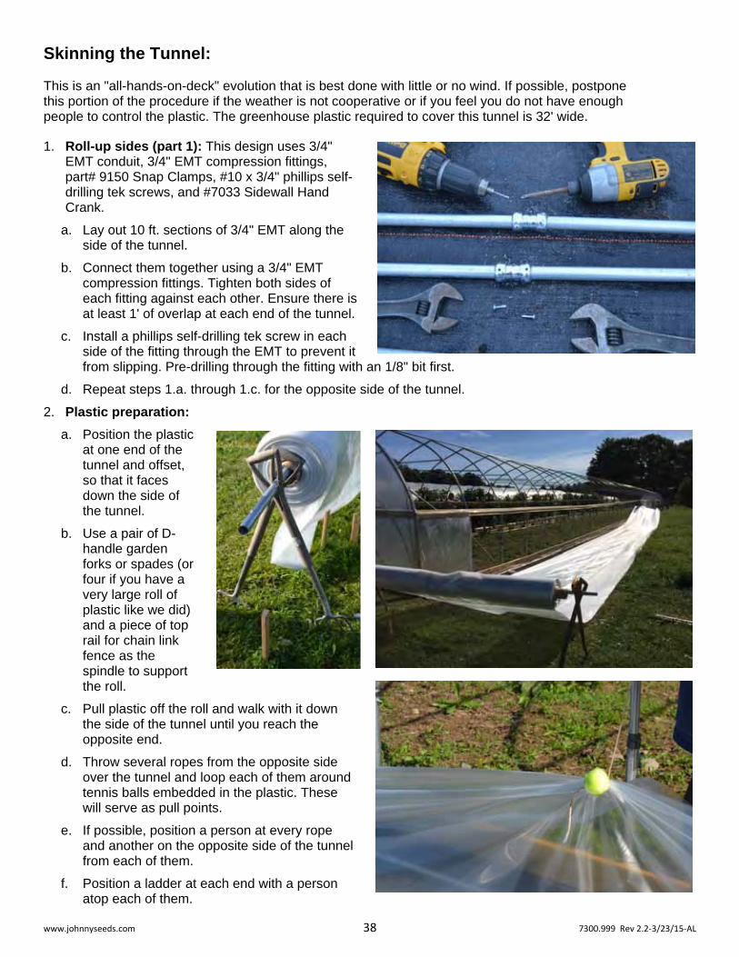
Skinning the Tunnel: This is an "all-hands-on-deck" evolution that is best done with little or no wind. If possible, postpone this portion of the procedure if the weather is not cooperative or if you feel you do not have enough people to control the plastic. The greenhouse plastic required to cover this tunnel is 32' wide.
1. Roll-up sides (part 1): This design uses 3/4" EMT conduit, 3/4" EMT compression fittings, part# 9150 Snap Clamps, #10 x 3/4" phillips self-drilling tek screws, and #7033 Sidewall Hand Crank.
a. Lay out 10 ft. sections of 3/4" EMT along the side of the tunnel.
b. Connect them together using a 3/4" EMT compression fittings. Tighten both sides of each fitting against each other. Ensure there is at least 1' of overlap at each end of the tunnel.
c. Install a phillips self-drilling tek screw in each side of the fitting through the EMT to prevent it from slipping. Pre-drilling through the fitting with an 1/8" bit first.
d. Repeat steps 1.a. through 1.c. for the opposite side of the tunnel.
2. Plastic preparation:
a. Position the plastic at one end of the tunnel and offset, so that it faces down the side of the tunnel.
b. Use a pair of D-handle garden forks or spades (or four if you have a very large roll of plastic like we did) and a piece of top rail for chain link fence as the spindle to support the roll.
c. Pull plastic off the roll and walk with it down the side of the tunnel until you reach the opposite end.
d. Throw several ropes from the opposite side over the tunnel and loop each of them around tennis balls embedded in the plastic. These will serve as pull points.
e. If possible, position a person at every rope and another on the opposite side of the tunnel from each of them.
f. Position a ladder at each end with a person atop each of them.
www.johnnyseeds.com 39 7300.999 Rev 2.2‐3/23/15‐AL
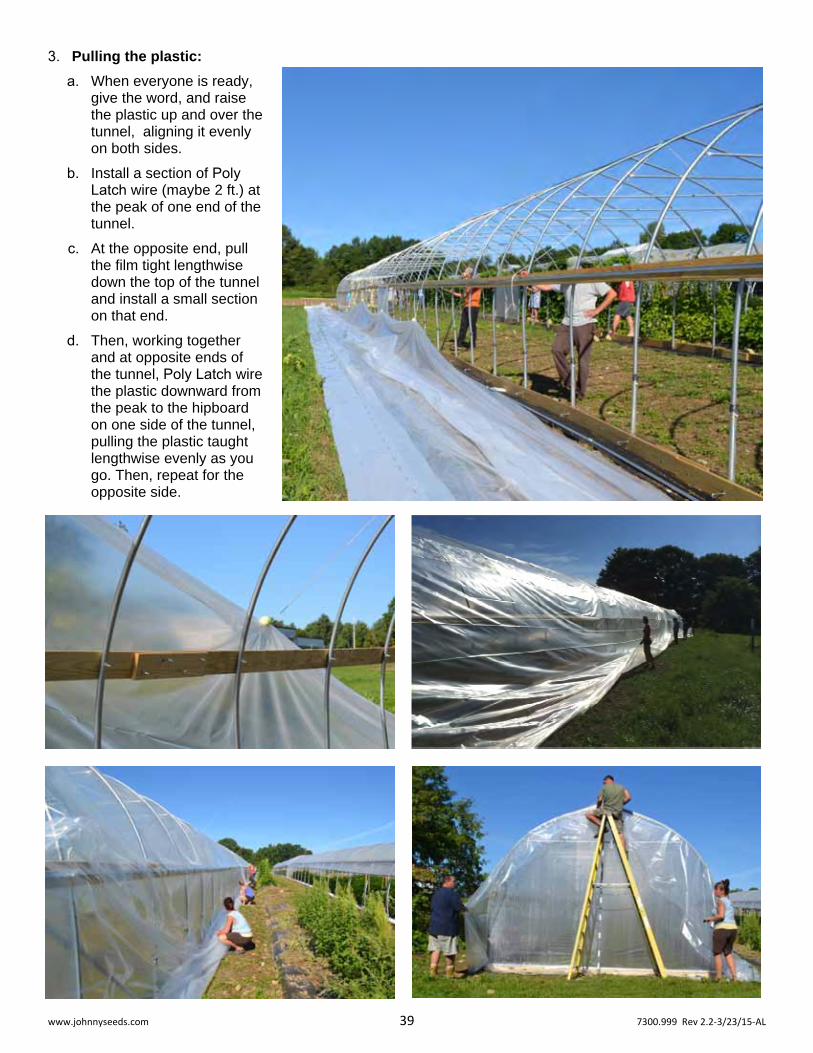
3. Pulling the plastic:
a. When everyone is ready, give the word, and raise the plastic up and over the tunnel, aligning it evenly on both sides.
b. Install a section of Poly Latch wire (maybe 2 ft.) at the peak of one end of the tunnel.
c. At the opposite end, pull the film tight lengthwise down the top of the tunnel and install a small section on that end.
d. Then, working together and at opposite ends of the tunnel, Poly Latch wire the plastic downward from the peak to the hipboard on one side of the tunnel, pulling the plastic taught lengthwise evenly as you go. Then, repeat for the opposite side.

www.johnnyseeds.com 40 7300.999 Rev 2.2‐3/23/15‐AL
4. Roll-up sides (part 2):
a. Lay the assembled EMT on the loose plastic at the bottom of one side of the tunnel. Wrap it around the EMT evenly and secure in place with Snap Clamps every two feet or so. Adjust the Snap Clamps as necessary, removing any wrinkles in the plastic and ensuring that the EMT is parallel to the baseboards. Repeat for the opposite side of the tunnel.
b. Install phillips self-drilling tek screws through all the Snap Clamps, into the EMT.
c. Trim the plastic as necessary. Trim it carefully at the ends because it can cause bunching, uneven rolling, and uneven venting.
d. Hand Cranks: Some adapters come with each Hand Crank for other sizes of pipe; you will not need them for this installation. Hold the Sidewall Hand Crank's drive shaft next to end of the long EMT assembly and make a mark even with the holes in the drive shaft. With a 1/4" bit, drill through both walls of the EMT at that mark. Insert the drive shaft into the EMT and ream through with the same bit. Secure with the hex bolt and nylock nut provided with the kit. Attach the handle to the spindle on the end of the hand crank.
e. Guide Rail: Hold a 10 ft. piece of 3/4" EMT up to the corner of the tunnel where one of the hand cranks will be located. Make a mark 2' above the top of the hipboard. Cut it to length. Slide the EMT assembly up against the baseboards of the tunnel and insert the cut piece of EMT through the roller guides in the hand crank and drive it into the ground at least a foot. When finished, it should be at least 6" taller than the top of the hipboard.
f. Turn the handle of the hand crank and take up some of the plastic until the roll is 12" off the ground. The mechanism will automatically hold the plastic at any height where you release it. Check for evenness along the length of the tunnel. Roll back down and adjust snap clamps as necessary. Repeat. When satisfied, roll all the way up. These take some tweaking, but once adjusted, they work very well.
g. Repeat steps 4.b. through 4.f. for the opposite side of the tunnel.
www.johnnyseeds.com 41 7300.999 Rev 2.2‐3/23/15‐AL
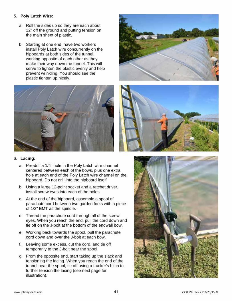
5. Poly Latch Wire:
a. Roll the sides up so they are each about 12" off the ground and putting tension on the main sheet of plastic.
b. Starting at one end, have two workers install Poly Latch wire concurrently on the hipboards at both sides of the tunnel, working opposite of each other as they make their way down the tunnel. This will serve to tighten the plastic evenly and help prevent wrinkling. You should see the plastic tighten up nicely.
6. Lacing:
a. Pre-drill a 1/4" hole in the Poly Latch wire channel centered between each of the bows, plus one extra hole at each end of the Poly Latch wire channel on the hipboard. Do not drill into the hipboard itself.
b. Using a large 12-point socket and a ratchet driver, install screw eyes into each of the holes.
c. At the end of the hipboard, assemble a spool of parachute cord between two garden forks with a piece of 1/2" EMT as the spindle.
d. Thread the parachute cord through all of the screw eyes. When you reach the end, pull the cord down and tie off on the J-bolt at the bottom of the endwall bow.
e. Working back towards the spool, pull the parachute cord down and over the J-bolt at each bow.
f. Leaving some excess, cut the cord, and tie off temporarily to the J-bolt near the spool.
g. From the opposite end, start taking up the slack and tensioning the lacing. When you reach the end of the tunnel near the spool, tie off using a trucker's hitch to further tension the lacing (see next page for illustration).

www.johnnyseeds.com 42 7300.999 Rev 2.2‐3/23/15‐AL
h. Repeat steps 6.a. through 6.g. for the opposite side of the tunnel.
The 14' Gothic High Tunnel is now complete!
A Trucker's Hitch is used to tension lacing on the roll-up sides.
www.johnnyseeds.com 43 7300.999 Rev 2.2‐3/23/15‐AL
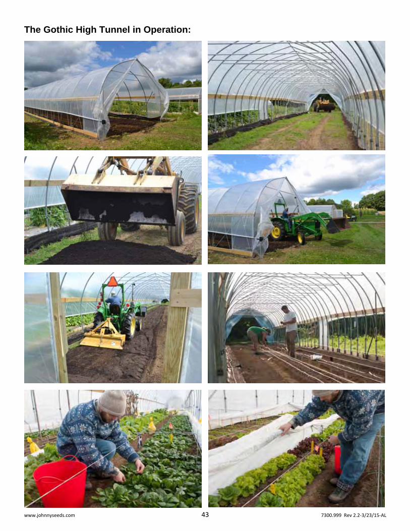
The Gothic High Tunnel in Operation: