Embed Size (px)
Citation preview
3900 – 101 Street Edmonton, Alberta, Canada T6E 0A5 Office: (780) 437-3055 Fax: (780) 436-5461
3516 114 Avenue SE Calgary, Alberta, Canada
T2Z 3V6Office: (403) 250-1416
Fax: (403) 291-9487 Website: www.cvs-controls.com E-Mail: [email protected]
CVS Series H-900, H-1500 and
H-2500 DesignValve Bodies
Contents Contained in this manual are installation instructions, maintenance procedures and parts information for the CVS Series H-900, H-1500 and H-2500 Design Valve Bodies. Refer to theappropriate manuals for instructions for theaccompanying actuator and additionalaccessories.
Trained or experienced personnel should carry out operation and installation of all pressure equipment. If you have any questions regarding the equipment, contact your CVS Controls representative. A serial number identifies each CVS Series H valve and is stamped on the valve body. Please reference this number when communicating with your CVS Controls representative.
Applications and Features The CVS Series H Control Valve provides excellent pressure and flow control on steam, gasses and various liquid applications.
The CVS Design H2D valve is a single port, globe body with cage guiding, and balanced valve plug with push down to close action. Suitable for general applications where tight shutoff is not required.
The CVS Design H5T valve is a single port, globe body with cage guiding, balanced valve plug, metal seat and pressure assisted spring seal to provide a seal between the valve plug and cage. Suitable for applications which require low leakage rates.
Instruction Manual
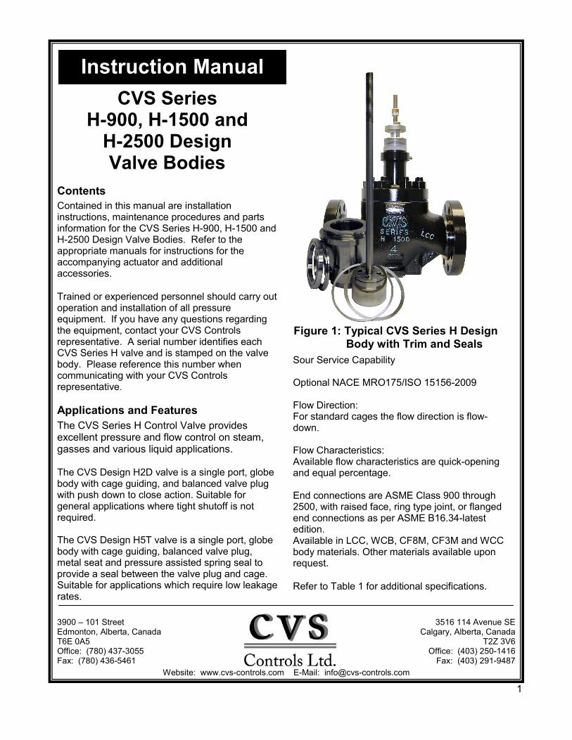
Figure 1: Typical CVS Series H Design Body with Trim and Seals
Sour Service Capability
Optional NACE MRO175/ISO 15156-2009
Flow Direction: For standard cages the flow direction is flow-down.
Flow Characteristics: Available flow characteristics are quick-opening and equal percentage.
End connections are ASME Class 900 through 2500, with raised face, ring type joint, or flanged end connections as per ASME B16.34-latest edition. Available in LCC, WCB, CF8M, CF3M and WCC body materials. Other materials available upon request.
Refer to Table 1 for additional specifications.
1
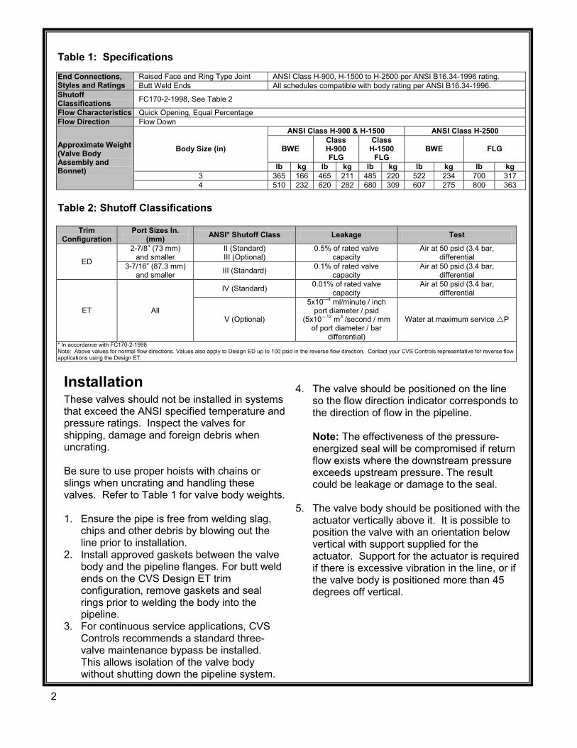
Installation These valves should not be installed in systems that exceed the ANSI specified temperature and pressure ratings. Inspect the valves for shipping, damage and foreign debris when uncrating.
Be sure to use proper hoists with chains or slings when uncrating and handling these valves. Refer to Table 1 for valve body weights.
1. Ensure the pipe is free from welding slag,chips and other debris by blowing out theline prior to installation.
2. Install approved gaskets between the valvebody and the pipeline flanges. For butt weldends on the CVS Design ET trimconfiguration, remove gaskets and sealrings prior to welding the body into thepipeline.
3. For continuous service applications, CVSControls recommends a standard three-valve maintenance bypass be installed.This allows isolation of the valve bodywithout shutting down the pipeline system.
4. The valve should be positioned on the lineso the flow direction indicator corresponds tothe direction of flow in the pipeline.
Note: The effectiveness of the pressure-energized seal will be compromised if returnflow exists where the downstream pressureexceeds upstream pressure. The resultcould be leakage or damage to the seal.
5. The valve body should be positioned with theactuator vertically above it. It is possible toposition the valve with an orientation belowvertical with support supplied for theactuator. Support for the actuator is requiredif there is excessive vibration in the line, or ifthe valve body is positioned more than 45degrees off vertical.
Table 1: Specifications
End Connections, Styles and Ratings
Raised Face and Ring Type Joint ANSI Class H-900, H-1500 to H-2500 per ANSI B16.34-1996 rating. Butt Weld Ends All schedules compatible with body rating per ANSI B16.34-1996.
Shutoff Classifications FC170-2-1998, See Table 2
Flow Characteristics Quick Opening, Equal Percentage Flow Direction Flow Down
Approximate Weight (Valve Body Assembly and Bonnet)
Body Size (in)
ANSI Class H-900 & H-1500 ANSI Class H-2500
BWE Class H-900FLG
Class H-1500
FLGBWE FLG
lb kg lb kg lb kg lb kg lb kg 3 365 166 465 211 485 220 522 234 700 317 4 510 232 620 282 680 309 607 275 800 363
Table 2: Shutoff Classifications
Trim Configuration
Port Sizes In. (mm) ANSI* Shutoff Class Leakage Test
ED
2-7/8” (73 mm)and smaller
II (Standard) III (Optional)
0.5% of rated valve capacity
Air at 50 psid (3.4 bar, differential
3-7/16” (87.3 mm)and smaller III (Standard) 0.1% of rated valve
capacity Air at 50 psid (3.4 bar,
differential
ET All
IV (Standard) 0.01% of rated valve capacity
Air at 50 psid (3.4 bar, differential
V (Optional)
5x10—4 ml/minute / inch port diameter / psid
(5x10—12 m3 /second / mm of port diameter / bar
differential)
Water at maximum service P
* In accordance with FC170-2-1998Note: Above values for normal flow directions. Values also apply to Design ED up to 100 psid in the reverse flow direction. Contact your CVS Controls representative for reverse flow applications using the Design ET.
2
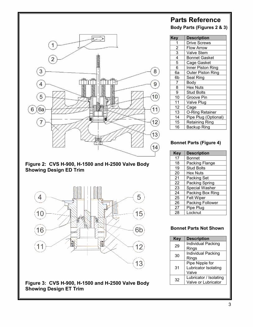
Figure 2: CVS H-900, H-1500 and H-2500 Valve Body Showing Design ED Trim
Figure 3: CVS H-900, H-1500 and H-2500 Valve Body Showing Design ET Trim
Parts Reference Body Parts (Figures 2 & 3) Key Description
1 Drive Screws 2 Flow Arrow 3 Valve Stem 4 Bonnet Gasket 5 Cage Gasket 6 Inner Piston Ring 6a Outer Piston Ring 6b Seal Ring 7 Body 8 Hex Nuts 9 Stud Bolts 10 Groove Pin 11 Valve Plug 12 Cage 13 O-Ring Retainer 14 Pipe Plug (Optional) 15 Retaining Ring 16 Backup Ring
Bonnet Parts (Figure 4)
Key Description 17 Bonnet 18 Packing Flange 19 Stud Bolts 20 Hex Nuts 21 Packing Set 22 Packing Spring 23 Special Washer 24 Packing Box Ring 25 Felt Wiper 26 Packing Follower 27 Pipe Plug 28 Locknut
Bonnet Parts Not Shown
Key Description
29 Individual Packing Rings
30 Individual Packing Rings
31 Pipe Nipple for Lubricator Isolating Valve
32 Lubricator / Isolating Valve or Lubricator
3
28 6
1
3
5
4
7
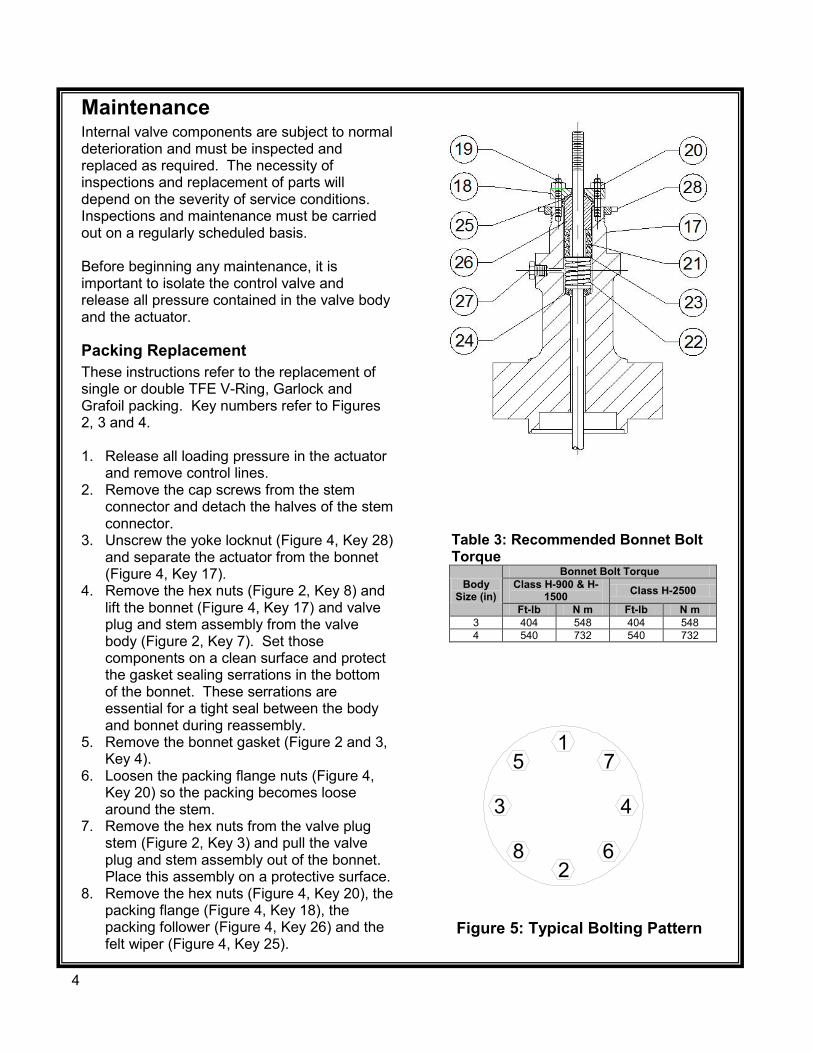
Maintenance Internal valve components are subject to normal deterioration and must be inspected and replaced as required. The necessity of inspections and replacement of parts will depend on the severity of service conditions. Inspections and maintenance must be carried out on a regularly scheduled basis. Before beginning any maintenance, it is important to isolate the control valve and release all pressure contained in the valve body and the actuator.
Packing Replacement These instructions refer to the replacement of single or double TFE V-Ring, Garlock and Grafoil packing. Key numbers refer to Figures 2, 3 and 4. 1. Release all loading pressure in the actuator
and remove control lines. 2. Remove the cap screws from the stem
connector and detach the halves of the stem connector.
3. Unscrew the yoke locknut (Figure 4, Key 28) and separate the actuator from the bonnet (Figure 4, Key 17).
4. Remove the hex nuts (Figure 2, Key 8) and lift the bonnet (Figure 4, Key 17) and valve plug and stem assembly from the valve body (Figure 2, Key 7). Set those components on a clean surface and protect the gasket sealing serrations in the bottom of the bonnet. These serrations are essential for a tight seal between the body and bonnet during reassembly.
5. Remove the bonnet gasket (Figure 2 and 3, Key 4).
6. Loosen the packing flange nuts (Figure 4, Key 20) so the packing becomes loose around the stem.
7. Remove the hex nuts from the valve plug stem (Figure 2, Key 3) and pull the valve plug and stem assembly out of the bonnet. Place this assembly on a protective surface.
8. Remove the hex nuts (Figure 4, Key 20), the packing flange (Figure 4, Key 18), the packing follower (Figure 4, Key 26) and the felt wiper (Figure 4, Key 25).
Figure 5: Typical Bolting Pattern
Table 3: Recommended Bonnet Bolt Torque
Body Size (in)
Bonnet Bolt Torque Class H-900 & H-
1500 Class H-2500
Ft-lb N m Ft-lb N m 3 404 548 404 548 4 540 732 540 732
4
Packing Replacement cont’d 9. Use a packing hook to remove the packing
parts, or push them toward the top of the bonnet using a small rod. Be careful not to scratch the wall of the packing box.
10. Clean the metal packing parts and the packing box, and check the valve stem and packing box surfaces for nicks or scratches. Remove any light scratches with sanding. If damage exists that cannot be sanded out, the valve plug stem and bonnet must be replaced.
11. Install a new bonnet gasket (Figures 2 and 3, Key 4) onto the cage (Figures 2 and 3, Key 12).
Note: The valve plug assembly of the ED and ET fit inside the cage with tight tolerances. When installing the valve plug assembly be sure not to damage the piston rings or the seal ring (Figures 2 and 3, Keys 6, 6a, 6b). When the bonnet is being mounted, the threads of the valve plug stem will slide through the packing box. If the packing has been installed, carefully attach the bonnet to avoid cutting the packing on the stem threads.
12. Insert the valve plug assembly in the cage,
mounting the bonnet onto the body. Ensure that the leak-off piping (or pipe plug, Figure 4, Key 27) is facing downstream.
13. Apply lubricant to the body stud bolts (Figures 2 and 3, Key 9) and the hex nuts (Figures 2 and 3, Key 8). Thread the nuts onto the body stud bolts using good bolting practices. Refer to Table 3 for proper bolt torques and tighten the nuts in a criss-cross pattern (See Figure 5). When the control valve assembly reaches operating temperature, repeat the procedure. Proper tightening of the bonnet nuts ensures a positive sealing of the cage seals and the spring seal.
Note: Repeating the bolting pattern may be necessary since tightening one nut may loosen an adjacent nut. The body-to-bonnet seal will be complete when none of the nuts will turn at the recommended torque.
14. Refer to Figure 4 and arrange the packing
parts as outlined. Slide the new packing carefully over the valve plug stem, and ensure that the packing parts are not damaged by the threads of the valve plug stem.
15. Reinstall the packing flange and hex nuts (Keys 18 and 20). Tighten the hex nuts until the shoulder of the packing follower (Key 26) is snug against the packing box.
16. Mount the actuator onto the valve body assembly and reconnect the actuator and valve stem referring to procedures in the appropriate actuator manual.
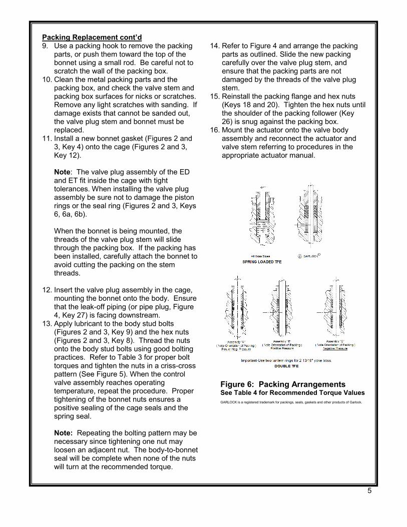
Figure 6: Packing Arrangements See Table 4 for Recommended Torque Values GARLOCK is a registered trademark for packings, seals, gaskets and other products of Garlock.
5
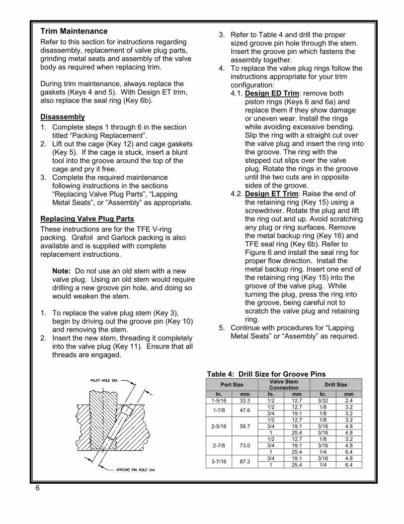
Table 4: Drill Size for Groove Pins Port Size Valve Stem
Connection Drill Size
In. mm In. mm In. mm 1-5/16 33.3 1/2 12.7 3/32 2.4
1-7/8 47.6 1/2 12.7 1/8 3.2 3/4 19.1 1/8 3.2
2-5/16 58.7 1/2 12.7 1/8 3.2 3/4 19.1 3/16 4.8 1 25.4 3/16 4.8
2-7/8 73.0 1/2 12.7 1/8 3.2 3/4 19.1 3/16 4.8 1 25.4 1/4 6.4
3-7/16 87.3 3/4 19.1 3/16 4.8 1 25.4 1/4 6.4
Trim Maintenance Refer to this section for instructions regarding disassembly, replacement of valve plug parts, grinding metal seats and assembly of the valve body as required when replacing trim. During trim maintenance, always replace the gaskets (Keys 4 and 5). With Design ET trim, also replace the seal ring (Key 6b).
Disassembly 1. Complete steps 1 through 6 in the section
titled “Packing Replacement”. 2. Lift out the cage (Key 12) and cage gaskets
(Key 5). If the cage is stuck, insert a blunt tool into the groove around the top of the cage and pry it free.
3. Complete the required maintenance following instructions in the sections “Replacing Valve Plug Parts”, “Lapping Metal Seats”, or “Assembly” as appropriate.
Replacing Valve Plug Parts These instructions are for the TFE V-ring packing. Grafoil and Garlock packing is also available and is supplied with complete replacement instructions. Note: Do not use an old stem with a new
valve plug. Using an old stem would require drilling a new groove pin hole, and doing so would weaken the stem.
1. To replace the valve plug stem (Key 3),
begin by driving out the groove pin (Key 10) and removing the stem.
2. Insert the new stem, threading it completely into the valve plug (Key 11). Ensure that all threads are engaged.
3. Refer to Table 4 and drill the proper sized groove pin hole through the stem. Insert the groove pin which fastens the assembly together.
4. To replace the valve plug rings follow the instructions appropriate for your trim configuration: 4.1. Design ED Trim: remove both
piston rings (Keys 6 and 6a) and replace them if they show damage or uneven wear. Install the rings while avoiding excessive bending. Slip the ring with a straight cut over the valve plug and insert the ring into the groove. The ring with the stepped cut slips over the valve plug. Rotate the rings in the groove until the two cuts are in opposite sides of the groove.
4.2. Design ET Trim: Raise the end of the retaining ring (Key 15) using a screwdriver. Rotate the plug and lift the ring out and up. Avoid scratching any plug or ring surfaces. Remove the metal backup ring (Key 16) and TFE seal ring (Key 6b). Refer to Figure 6 and install the seal ring for proper flow direction. Install the metal backup ring. Insert one end of the retaining ring (Key 15) into the groove of the valve plug. While turning the plug, press the ring into the groove, being careful not to scratch the valve plug and retaining ring.
5. Continue with procedures for “Lapping Metal Seats” or “Assembly” as required.
6
Lapping Metal Seats While some leakage is expected with any metal-to-metal seating in a valve body, excessive leakage can be improved by lapping or grinding the valve plug and seat ring. Deep nicks should be machined out. A good quality commercial-grade lapping compound should be used. Apply lapping compound to the valve plug seating surface. During lapping, the bonnet must be bolted to the body and the gaskets (old gaskets may be used) in place in order to keep the valve plug in line with the seat ring. A simple grinding tool can be made using a piece of strap iron fastened to the valve plug stem with nuts. Rotate the handle in opposite directions to lap the seating surfaces. After grinding, remove the bonnet and clean the seating surfaces. Test for proper shutoff and repeat the process if necessary.
Assembly Caution must be used when working around the sealing surfaces. Any nicks or scratches will compromise the sealing ability. Prior to installing the seals, the sealing surface should be wiped with a clean cloth. 1. Install the o-ring retainer (Key 13) into the
valve body. 2. Install the cage gasket (Key 5). 3. Install the cage (Key 12) into the valve body. 4. Proceed with steps 11 through 16 of the
section titled “Packing Replacement”.
Parts Ordering Valves manufactured by CVS Controls have individual serial numbers, found on the valve nameplate. Please refer to that number when ordering parts or contacting your CVS Controls Sales Representative. Individual part numbers are listed in the following section. Please include these numbers when ordering replacement parts.
7
CVS Series H-900, H-1500 and H-2500 Design Valve Bodies Key Description Part Number
1 Drive Screws, SST (2 req’d) CVS1A368228982 2 Flow Arrow, SST CVS1V106038982 3 Valve Stem See Following Tables
4 Bonnet Gasket* Class H-900 and Class H-1500 3” Body Size CVS10A4154X012
4” Body Size CVS10A5457X012
Class H-2500 3” Body Size CVS10A4107X012 4” Body Size CVS10A4154X012
5 Cage Gasket Class H-900 and Class H-1500 3” Body Size CVS10A4155X012
4” Body Size CVS10A5458X012
Class H-2500 3” Body Size CVS10A4108X012 4” Body Size CVS10A4155X012
6 Piston Ring or Seal Ring See Following Tables 7 Body See Following Tables 8 Hex Nuts See Following Tables 9 Stud Bolts See Following Tables
10 Groove Pin See Following Tables 11 Valve Plug See Following Tables 12 Cage See Following Tables 13 O-Ring Retainer See Following Tables
14 Pipe Plug (Optional) Steel for LCC and WCB Bodies CVS1A771528992 316SST for CF8M Bodies CVS1A771535072
15 Retaining Ring See Following Tables 16 Backup Ring See Following Tables 17 Bonnet See Following Tables
18 Packing Flange 2-13/16” Boss, 1/2” Stem Steel (Standard) CVS1E944223072
316 SST CVS1F380335072
3-9/16” Boss, 3/4” Stem Steel (Standard) CVS1E944823072 316 SST CVS1F380435072
19 Stud Bolts (2 Req’d) 2-13/16” Boss, 1/2” Stem Steel (Standard) CVS1E944431032
316 SST CVS1E944435222
3-9/16” Boss, 3/4” Stem Steel (Standard) CVS1E944931032 316 SST CVS1E944935222
20 Hex Nuts (2 Req’d) 2-13/16” Boss, 1/2” Stem Steel (Standard) CVS1E944524112
316 SST CVS1E944535252
3-9/16” Boss, 3/4” Stem Steel (Standard) CVS1E944624112 316 SST CVS1E944635252
21 Packing Set See Following Tables 22 Lantern Ring or Spring See Following Tables 23 Special Washer See Following Tables 24 Packing Box Ring See Following Tables 25 Felt Wiper See Following Tables 26 Packing Follower See Following Tables
27 Pipe Plug Steel, for LCC and LCB Bodies CVS1A767524662 316SST for CF8M Bodies CVS1A767535072
28 Locknut, Steel 2-13/16” Boss, 1/2” Stem CVS1E807423062 3-9/16” Boss, 3/4” Stem CVS1E832723062
29 Packing Ring See Following Tables 30 Packing Ring See Following Tables
31 Pipe Nipple for Lubricator Isolating Valve
For LCC Bonnets CVS1D239726232 For all other Bonnets CVS1B292738332
32 Lubricator / Isolating Valve CVSAJ5428000A2 Lubricator CVS0V0873000A2
* Recommended Spare Part
8
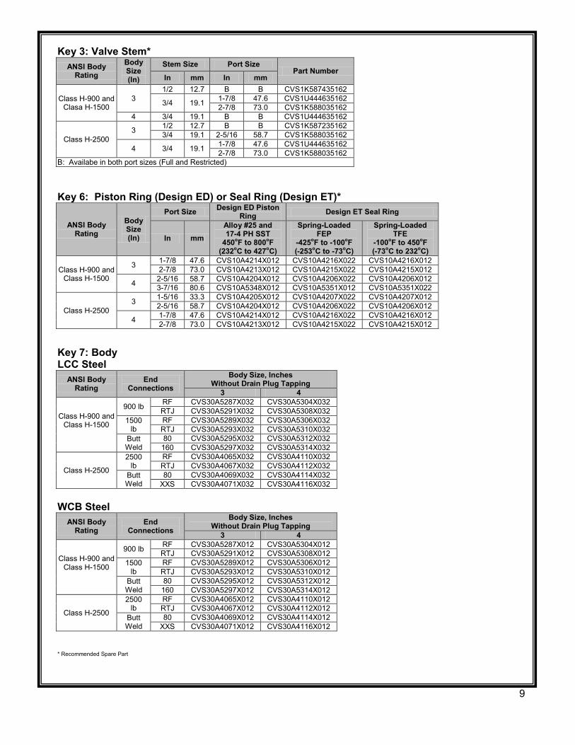
Key 3: Valve Stem* ANSI Body
Rating Body Size (In)
Stem Size Port Size Part Number
In mm In mm
Class H-900 and Clasa H-1500
3 1/2 12.7 B B CVS1K587435162
3/4 19.1 1-7/8 47.6 CVS1U444635162 2-7/8 73.0 CVS1K588035162
4 3/4 19.1 B B CVS1U444635162
Class H-2500 3 1/2 12.7 B B CVS1K587235162
3/4 19.1 2-5/16 58.7 CVS1K588035162
4 3/4 19.1 1-7/8 47.6 CVS1U444635162 2-7/8 73.0 CVS1K588035162
B: Availabe in both port sizes (Full and Restricted) Key 6: Piston Ring (Design ED) or Seal Ring (Design ET)*
ANSI Body Rating
Body Size (In)
Port Size Design ED Piston Ring Design ET Seal Ring
In mm Alloy #25 and 17-4 PH SST
450oF to 800oF (232oC to 427oC)
Spring-Loaded FEP
-425oF to -100oF (-253oC to -73oC)
Spring-Loaded TFE
-100oF to 450oF (-73oC to 232oC)
Class H-900 and Class H-1500
3 1-7/8 47.6 CVS10A4214X012 CVS10A4216X022 CVS10A4216X012 2-7/8 73.0 CVS10A4213X012 CVS10A4215X022 CVS10A4215X012
4 2-5/16 58.7 CVS10A4204X012 CVS10A4206X022 CVS10A4206X012 3-7/16 80.6 CVS10A5348X012 CVS10A5351X012 CVS10A5351X022
Class H-2500 3 1-5/16 33.3 CVS10A4205X012 CVS10A4207X022 CVS10A4207X012
2-5/16 58.7 CVS10A4204X012 CVS10A4206X022 CVS10A4206X012
4 1-7/8 47.6 CVS10A4214X012 CVS10A4216X022 CVS10A4216X012 2-7/8 73.0 CVS10A4213X012 CVS10A4215X022 CVS10A4215X012
Key 7: Body LCC Steel
ANSI Body Rating
End Connections
Body Size, Inches Without Drain Plug Tapping
3 4
Class H-900 and Class H-1500
900 lb RF CVS30A5287X032 CVS30A5304X032 RTJ CVS30A5291X032 CVS30A5308X032
1500 lb
RF CVS30A5289X032 CVS30A5306X032 RTJ CVS30A5293X032 CVS30A5310X032
Butt Weld
80 CVS30A5295X032 CVS30A5312X032 160 CVS30A5297X032 CVS30A5314X032
Class H-2500
2500 lb
RF CVS30A4065X032 CVS30A4110X032 RTJ CVS30A4067X032 CVS30A4112X032
Butt Weld
80 CVS30A4069X032 CVS30A4114X032 XXS CVS30A4071X032 CVS30A4116X032
WCB Steel
ANSI Body Rating
End Connections
Body Size, Inches Without Drain Plug Tapping
3 4
Class H-900 and Class H-1500
900 lb RF CVS30A5287X012 CVS30A5304X012 RTJ CVS30A5291X012 CVS30A5308X012
1500 lb
RF CVS30A5289X012 CVS30A5306X012 RTJ CVS30A5293X012 CVS30A5310X012
Butt Weld
80 CVS30A5295X012 CVS30A5312X012 160 CVS30A5297X012 CVS30A5314X012
Class H-2500
2500 lb
RF CVS30A4065X012 CVS30A4110X012 RTJ CVS30A4067X012 CVS30A4112X012
Butt Weld
80 CVS30A4069X012 CVS30A4114X012 XXS CVS30A4071X012 CVS30A4116X012
* Recommended Spare Part
9
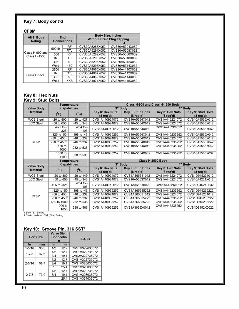
Key 7: Body cont’d CF8M
ANSI Body Rating
End Connections
Body Size, Inches Without Drain Plug Tapping
3 4
Class H-900 and Class H-1500
900 lb RF CVS30A5287X052 CVS30A5304X052 RTJ CVS30A5291X052 CVS30A5308X052
1500 lb
RF CVS30A5289X052 CVS30A5306X052 RTJ CVS30A5293X052 CVS30A5310X052
Butt Weld
80 CVS30A5295X052 CVS30A5312X052 160 CVS30A5297X052 CVS30A5314X052
Class H-2500
2500 lb
RF CVS30A4065X052 CVS30A4110X052 RTJ CVS30A4067X052 CVS30A4112X052
Butt Weld
80 CVS30A4069X052 CVS30A4114X052 XXS CVS30A4071X052 CVS30A4116X052
Key 8: Hex Nuts Key 9: Stud Bolts
Valve Body Material
Temperature Capabilities
Class H-900 and Class H-1500 Body 3” Body 4” Body
(oF) (oC) Key 8: Hex Nuts (8 req’d)
Key 9: Stud Bolts (8 req’d)
Key 8: Hex Nuts (8 req’d)
Key 9: Stud Bolts (8 req’d)
WCB Steel -20 to 800 -29 to 427 CVS1A440924072 CVS10A5564X012 CVS1A445224072 CVS10A5565X012 LCC Steel -50 to 650 -45 to 343 CVS1A440924072 CVS10A5564X012 CVS1A445224072 CVS10A5565X012
CF8M
-425 to -325
-254 to -198 CVS1A4409X0012 CVS10A5564X062 CVS1A4452X0022 CVS10A5565X062
-325 to -50 -198 to -46 CVS1A440935252 CVS10A5564X042 CVS1A445235252 CVS10A5565X042 -50 to 4501 -46 to 232 CVS1A440924072 CVS10A5564X012 CVS1A445224072 CVS10A5565X012 -50 to 4502 -46 to 232 CVS1A440935252 CVS10A5564X042 CVS1A445235252 CVS10A5565X042
450 to 1000 232 to 538 CVS1A440935252 CVS10A5564X042 CVS1A445235252 CVS10A5565X042
1000 to 1100 538 to 593 CVS1A440935252 CVS10A5564X032 CVS1A445235252 CVS10A5565X032
Valve Body
Material
Temperature Capabilities
Class H-2500 Body 3” Body 4” Body
(oF) (oC) Key 8: Hex Nuts (8 req’d)
Key 9: Stud Bolts (8 req’d)
Key 8: Hex Nuts (8 req’d)
Key 9: Stud Bolts (8 req’d)
WCB Steel -20 to 300 -29 to 149 CVS1A440924072 CVS1A365631012 CVS1A445224072 CVS1D945231012 LCC Steel -50 to 650 -45 to 343 CVS1A440924072 CVS10A5563X012 CVS1A445224072 CVS10A4221X012
CF8M
-425 to -325 -254 to -198 CVS1A4409X0012 CVS1A3656X0022 CVS1A4452X0022 CVS1D9452X0032
-325 to -50 -198 to -46 CVS1A440935252 CVS1A365635222 CVS1A445235252 CVS1D945235222 -50 to 4501 -46 to 232 CVS1A440924072 CVS1A365631012 CVS1A445224072 CVS1D945231012 -50 to 4502 -46 to 232 CVS1A440935252 CVS1A365635222 CVS1A445235252 CVS1D945235222
450 to 1000 232 to 538 CVS1A440935252 CVS1A365635222 CVS1A445235252 CVS1D945235222 1000 to
1050 538 to 566 CVS1A440935252 CVS1A3656X0012 CVS1A445235252 CVS1D9452X0022 1 Steel (B7) Bolting 2 Strain Hardened SST (B8M) Bolting
Key 10: Groove Pin, 316 SST*
Port Size Valve Stem Connectio
n ED, ET
In mm In mm 1-5/16 33.3 1/2 12.7 CVS1V322635072
1-7/8 47.6 1/2 12.7 CVS1V322735072 3/4 19.1 CVS2V322735072
2-5/16 58.7 1/2 12.7 CVS1V322735072 3/4 19.1 CVS1V326035072 1 25.4 CVS1V326035072
2-7/8 73.0 1/2 12.7 CVS1V322735072 3/4 19.1 CVS1V326035072 1 25.4 CVS1V334035072
10
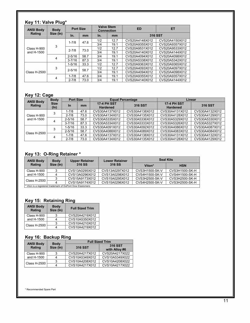
Key 11: Valve Plug* ANSI Body
Rating Body
Size (In) Port Size Valve Stem
Connection ED ET
In. mm In. mm 316 SST
Class H-900 and H-1500
3 1-7/8 47.6 1/2 12.7 CVS20A4148X012 CVS20A4150X012
3/4 19.1 CVS20A9355X012 CVS20A9357X012
2-7/8 73.0 1/2 12.7 CVS20A9531X012 CVS20A9533X012 3/4 19.1 CVS20A4140X012 CVS20A4144X012
4 2-5/16 58.7 3/4 19.1 CVS20A4094X012 CVS20A4098X012 3-7/16 87.3 3/4 19.1 CVS20A5338X012 CVS20A5342X012
Class H-2500 3
1-5/16 33.3 1/2 12.7 CVS20A9363X012 CVS20A9365X012
2-5/16 58.7 1/2 12.7 CVS20A4093X012 CVS20A4097X012 3/4 19.1 CVS20A4094X012 CVS20A4098X012
4 1-7/8 47.6 3/4 19.1 CVS20A9355X012 CVS20A9357X012 2-7/8 73.0 3/4 19.1 CVS20A4140X012 CVS20A4144X012
Key 12: Cage
ANSI Body Rating
Body Size (In)
Port Size Equal Percentage Linear
In mm 17-4 PH SST Hardened 316 SST 17-4 PH SST
Hardened 316 SST
Class H-900 and H-1500
3 1-7/8 47.6 CVS30A4137X012 CVS30A4138X012 CVS30A4131X012 CVS30A4132X012 2-7/8 73.0 CVS30A4134X012 CVS30A4135X012 CVS30A4128X012 CVS30A4129X012
4 2-5/16 58.7 CVS30A5335X012 CVS30A5336X012 CVS30A5329X012 CVS30A5330X012 3-7/16 87.3 CVS30A5334X012 CVS30A5333X012 CVS30A5326X012 CVS30A5327X012
Class H-2500 3 1-5/16 33.3 CVS30A4091X012 CVS30A4092X012 CVS30A4086X012 CVS30A4087X012
2-5/16 58.7 CVS30A4088X012 CVS30A4089X012 CVS30A4083X012 CVS30A4084X012
4 1-7/8 47.6 CVS30A4137X012 CVS30A4138X012 CVS30A4131X012 CVS30A4132X012 2-7/8 73.0 CVS30A4134X012 CVS30A4135X012 CVS30A4128X012 CVS30A4129X012
Key 13: O-Ring Retainer *
ANSI Body Rating
Body Size (In)
Upper Retainer 316 SS
Lower Retainer 316 SS
Seal Kits
Viton* HSN Class H-900 and H-1500
3 CVS13A0295X012 CVS13A0297X012 CVS3H1500-SK-V CVS3H1500-SK-H 4 CVS13A0296X012 CVS13A0298X012 CVS4H1500-SK-V CVS4H1500-SK-H
Class H-2500 3 CVS15A9173X012 CVS15A0295X012 CVS3H2500-SK-V CVS3H2500-SK-H 4 CVS15A9174X012 CVS15A0296X012 CVS4H2500-SK-V CVS3H2500-SK-H
* Viton is a registered trademark of DuPont Dow Elastomers
Key 15: Retaining Ring
ANSI Body Rating
Body Size (In) Full Sized Trim
Class H-900 and H-1500
3 CVS20A4219X012 4 CVS10A5350X012
Class H-2500 3 CVS10A4210X012 4 CVS10A4219X012
Key 16: Backup Ring
ANSI Body Rating
Body Size (In)
Full Sized Trim
316 SST 316 SST with Alloy #6
Class H-900 and H-1500
3 CVS20A4217X012 CVS20A4217X022 4 CVS10A5349X012 CVS10A5349X022
Class H-2500 3 CVS10A4208X012 CVS10A4208X022 4 CVS10A4217X012 CVS10A4217X022
* Recommended Spare Part
11
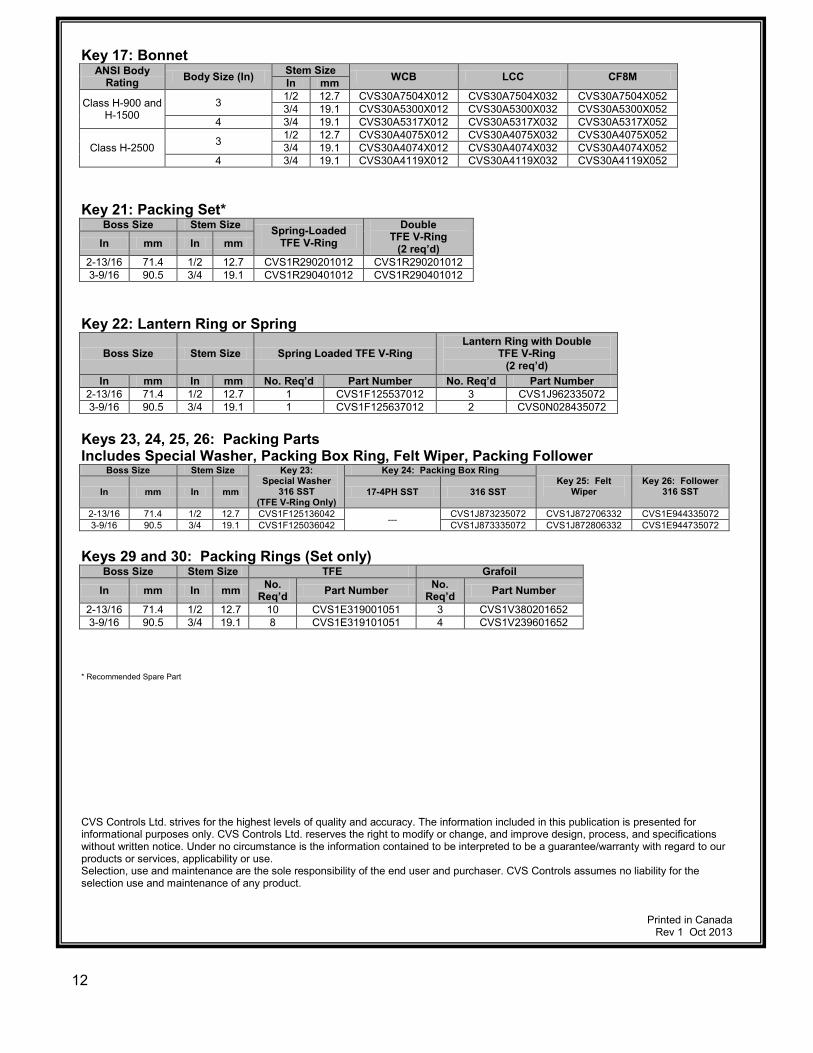
Key 17: Bonnet ANSI Body
Rating Body Size (In) Stem Size WCB LCC CF8M In mm
Class H-900 and H-1500
3 1/2 12.7 CVS30A7504X012 CVS30A7504X032 CVS30A7504X052 3/4 19.1 CVS30A5300X012 CVS30A5300X032 CVS30A5300X052
4 3/4 19.1 CVS30A5317X012 CVS30A5317X032 CVS30A5317X052
Class H-2500 3 1/2 12.7 CVS30A4075X012 CVS30A4075X032 CVS30A4075X052 3/4 19.1 CVS30A4074X012 CVS30A4074X032 CVS30A4074X052
4 3/4 19.1 CVS30A4119X012 CVS30A4119X032 CVS30A4119X052
Key 21: Packing Set* Boss Size Stem Size Spring-Loaded
TFE V-Ring Double
TFE V-Ring (2 req’d) In mm In mm
2-13/16 71.4 1/2 12.7 CVS1R290201012 CVS1R290201012 3-9/16 90.5 3/4 19.1 CVS1R290401012 CVS1R290401012
Key 22: Lantern Ring or Spring
Boss Size Stem Size Spring Loaded TFE V-Ring Lantern Ring with Double
TFE V-Ring (2 req’d)
In mm In mm No. Req’d Part Number No. Req’d Part Number 2-13/16 71.4 1/2 12.7 1 CVS1F125537012 3 CVS1J962335072 3-9/16 90.5 3/4 19.1 1 CVS1F125637012 2 CVS0N028435072
Keys 23, 24, 25, 26: Packing Parts Includes Special Washer, Packing Box Ring, Felt Wiper, Packing Follower
Boss Size Stem Size Key 23: Special Washer
316 SST (TFE V-Ring Only)
Key 24: Packing Box Ring Key 25: Felt
Wiper Key 26: Follower
316 SST In mm In mm 17-4PH SST 316 SST
2-13/16 71.4 1/2 12.7 CVS1F125136042 --- CVS1J873235072 CVS1J872706332 CVS1E944335072 3-9/16 90.5 3/4 19.1 CVS1F125036042 CVS1J873335072 CVS1J872806332 CVS1E944735072
Keys 29 and 30: Packing Rings (Set only) Boss Size Stem Size TFE Grafoil
In mm In mm No. Req’d Part Number No.
Req’d Part Number
2-13/16 71.4 1/2 12.7 10 CVS1E319001051 3 CVS1V380201652 3-9/16 90.5 3/4 19.1 8 CVS1E319101051 4 CVS1V239601652
* Recommended Spare Part
CVS Controls Ltd. strives for the highest levels of quality and accuracy. The information included in this publication is presented for informational purposes only. CVS Controls Ltd. reserves the right to modify or change, and improve design, process, and specifications without written notice. Under no circumstance is the information contained to be interpreted to be a guarantee/warranty with regard to our products or services, applicability or use. Selection, use and maintenance are the sole responsibility of the end user and purchaser. CVS Controls assumes no liability for the selection use and maintenance of any product.
Printed in Canada Rev 1 Oct 2013
12


![-ravichandran@uiowa.edu] CVS Health (CVS) September … · Through the above service, CVS helps clients in designing ... Improvement, and Modernization ... prescriptions at CVS Pharmacy](https://img.pdfslide.us/doc/110x75/5b5140327f8b9a056a8bdae7/-ravichandranuiowaedu-cvs-health-cvs-september-through-the-above-service.jpg)