Embed Size (px)
Citation preview
1
Website: www.cvs-controls.com E-Mail: [email protected]
CVS Series E 8-Inch Globe
Valves Design “ED” and “ET”
Introduction Contained in this manual are installation instructions, maintenance procedures and parts information for the 8-inch designs CVS Series E Valve Body. Refer to the appropriate manuals for the accompanying actuator, positioner and additional accessories. Trained or experienced personnel should carry out operation and installation of all pressure equipment. If you have any questions regarding the equipment, contact your CVS Controls representative.
Description The CVS Series E is a single port, globe-style body with composition or metal seats and a balanced push-down-to-close valve action plug. There are two styles of valve available: 1. Design ED is intended for general control
applications over a wide variety of temperatures and pressure drops. This design has an upper piston ring seal and metal-to-metal seating.
2. Design ET is intended for applications requiring
low leakage rates with composition seating (TFE) for tight shutoff requirements or metal-to-metal seating for higher temperature capabilities. The valve plug has a two-piece upper seal.
Instruction Manual
Figure 1: CVS Series E 8-Inch Control Valve with CVS 667 Diaphragm Actuator
For standard cages the flow direction is flow-down. The following flow characteristics are available: linear, quick opening and equal percent. The end connections are ANSI Class 150, 300 and 600 Raised Face, or Ring Type Joint flanges as per ASME B16.34-1996. The approximate shipping weight is 900 lbs (408 kg).
Head Office 3900 – 101 Street Edmonton, Alberta, Canada T6E 0A5 Office: (780) 437-3055 Fax: (780) 436-5461
Calgary Sales Office 205, 2323 – 32 Avenue NE Calgary, Alberta, Canada T2E 6Z3 Office: (403) 250-1416 Fax: (403) 291-9487
2
Installation The CVS 8” Series E valve should not be installed in systems that exceed the ANSI specified temperature and pressure ratings. Inspect the valves for shipping damage and foreign debris when uncrating. 1. Ensure the pipe is free of welding slag, chips,
and other debris by cleaning out the lines before installation.
2. Install approved gaskets between the valve body and the pipeline flanges.
3. CVS Controls recommends a standard three-valve maintenance bypass be installed. This allows isolation of the valve body without shutting down the pipeline system.
4. Install the valve so that the flow direction arrow on the body coincides with the actual process flow through the valve.
5. Although the valve can be installed in any position, the typical installation has the actuator vertical above the valve body. Support for the actuator will be necessary if there is vibration in the line or if the valve body is positioned 45 degrees or more below vertical.
Maintenance Before beginning any maintenance, it is important to isolate the control valve and release all pressure contained in the valve body and the actuator. Disconnect any operating lines providing air pressure, control signals or electrical power to the actuator.
Note: Caution must be used in the disassembly. The seating surfaces and surface finish of the cage; seat ring, stem, and plug are critical for proper sealing. Nicks and scratches will affect the ability to seal the valve in the future.
Disassembly 1. Disconnect and remove the actuator from the
body. 2. Remove the nuts or cap screws from the bonnet
flange. 3. Thread one of the actuator stem locknuts onto
the stem and continue threading it down to the bottom of the thread run out.
4. Remove the bonnet by lifting it straight up with a hoist. Attach the hoist by either a double cable hoisting sling under the bonnet or by the lifting rings attached to the packing flange stud bolts or on the 5” yoke bosses to two yoke stud bolts 180° apart.
5. Caution must be used when lifting the bonnet to ensure that it clears the body and stud bolts completely. Any damage to the seating surface will compromise future sealing ability
6. To prevent damage to the seating surface, place the bonnet-valve plug assembly on a wooden or cushioned surface.
Replacing the Plug Stem or Load Ring 1. Unscrew the locknuts from the stem. 2. Loosen the packing flange nuts. 3. Lean the bonnet over. 4. Draw the plug and stem out of the bonnet. 5. If valve plug is damaged it will be necessary to
replace both the valve plug and stem. If the stem is damaged, a new valve stem can be inserted in the original valve plug.
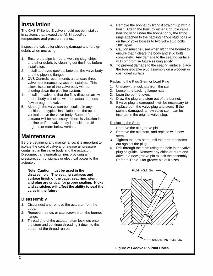
Replacing the Stem 1. Remove the old groove pin 2. Remove the old stem, and replace with new
stem. 3. Tighten the new stem until the thread bottoms
out against the plug. 4. Drill through the stem using the hole in the valve
plug as guide. Remove any chips or burrs and drive in a new groove pin to lock the assembly. Refer to Table 1 for groove pin drill sizes.
Figure 2: Groove Pin Pilot Holes
3
Table 1: Stem Torque and Groove Pin Drill Sizes
Valve Stem Connection (VSC)
Torque Min/Max Values
Groove Pin Drill Size
Inches mm Lbf-Ft N m Inches 3/4 19.1 237-339 175-250 3/16 1 25.4 420-481 310-355 1/4
Note: Use a new groove pin when installing a new stem. Vibration may loosen the stem if using an old groove pin.
Assembly 1. Ensure all gasket surfaces are clean. 2. Replace the valve plug piston ring or seal ring
with a new ring. 3. Assembly for design:
3.1. “CVS ED” Design Bodies: For valve bodies using a carbon filled TFE piston ring, at the split, slightly spread the ring and install it over the stem and into the piston ring groove on the valve plug.
Graphite piston rings are supplied as a complete ring and must be broken into two sections. The piston ring can be broken in half by scoring, and then breaking over a hard surface i.e.) edge of a table. Ensure the broken ends are re-matched when the piston ring is installed in the piston ring groove.
3.2. “CVS ET” Design Bodies: Apply a lubricant to both back-up ring and seal rings. Install the back-up ring over the stem and into the piston ring groove. Place the seal ring over the top edge of the valve plug, so that it slips into the groove on one side of the valve plug. Cautiously stretch the seal ring to work it over the top edge of the valve plug. Avoid jerking sharply on the seal, as the TFE in the seal ring needs time to cold flow during the stretching procedure. This stretching procedure may make the seal ring seem loose in the groove, however it will contract to its original size after installation of the cage.
4. Replace the seat ring gasket, and install the seat ring. If using a composition seat (TFE), assemble it by placing the TFE disc onto the disc retainer and then sliding this assembly over the disc seat.
5. Place the cage onto the seat ring. Any rotational orientation of the cage with respect to the valve body is acceptable.
6. To ensure a good seal, clean all sealing surfaces and examine surfaces for nicks and scratches. Place the bonnet gasket in position.
7. Slide the valve plug assembly in the cage, and then position the load ring on top of the cage.
8. Place the bonnet on the body ensuring that the pipe plug (or lubricator) is on the downstream side of the body.
9. Using good bolting practices, bolt the bonnet to the body. Lubricate the studs and nuts using good quality lubrication. Tighten the bolts alternately. Correct tightening of the bonnet bolts accomplishes two objectives. 9.1. To compress the bonnet gasket to form a
seal with the body joint. 9.2. Bolt loads are transmitted to the cage
through the load ring, which creates a sealing load for the seat ring gasket.
10. Mount the actuator to the bonnet and make up the stem connection. Refer to “Making Up the Stem Connection” for proper procedure.
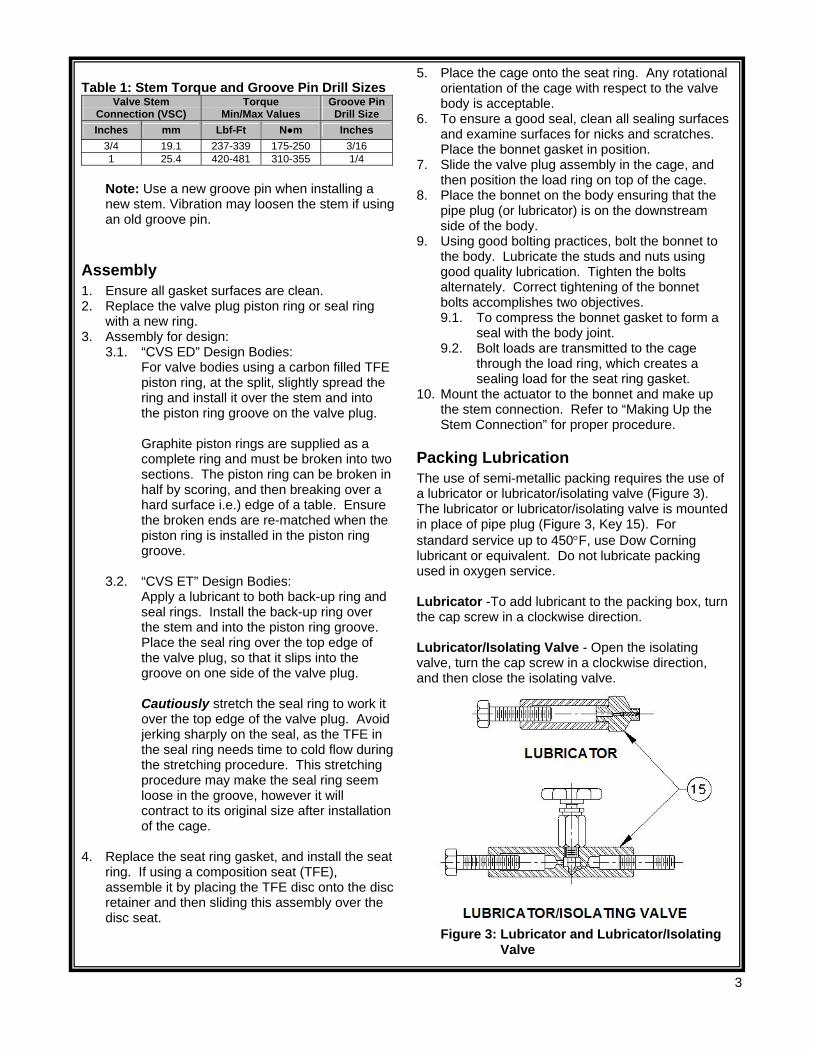
Packing Lubrication The use of semi-metallic packing requires the use of a lubricator or lubricator/isolating valve (Figure 3). The lubricator or lubricator/isolating valve is mounted in place of pipe plug (Figure 3, Key 15). For standard service up to 450°F, use Dow Corning lubricant or equivalent. Do not lubricate packing used in oxygen service. Lubricator -To add lubricant to the packing box, turn the cap screw in a clockwise direction. Lubricator/Isolating Valve - Open the isolating valve, turn the cap screw in a clockwise direction, and then close the isolating valve.
Figure 3: Lubricator and Lubricator/Isolating Valve
4
Table 3: Torque Values for Packing Flange Nuts
Valve Stem Diameter PTFE Type Packing Graphite Type Packing Min. Torque Max. Torque Min. Torque Max. Torque Inches Mm
ANSI Rating Lbf-in N m Lbf-in N m Lbf-in N m Lbf-in N m
150 47 5 70 8 99 11 149 17 300 64 7 95 11 133 15 199 23 3/4 19.1 600 87 10 131 15 182 21 274 31 300 108 12 162 18 226 26 339 38 1 25.4 600 149 17 223 25 310 35 466 53
Replacing TFE V-Ring Packing 1. After the stem and valve plug have been
detached from the bonnet, the following parts can be removed: 1.1. Packing nuts 1.2. Packing flange 1.3. Wiper ring 1.4. Packing follower
2. The old packing can be removed by one of two methods: 2.1. Remove the packing by pushing it out using
a rod inserted through bottom of the bonnet. 2.2. Use a packing hook to remove the packing.
Note: To avoid damaging the packing box walls use caution.
3. Clean the packing box bore, and all metal parts. Complete all required maintenance.
4. Slide the valve plug into the cage already in the valve body, install the load ring on the cage, and use a new bonnet gasket. Mount the bonnet to the valve body.
5. Complete the installation of the packing as illustrated in Figure 4.
Note: Extra caution should be taken not to damage the packing during the installation process.
6. Replace the packing flange (Key 27); tighten the packing flange nuts (Key 29) until shoulder of packing follower (Key 30) is approximately 5/8” from the top of the bonnet. If leakage is detected around the packing follower, tighten the packing flange nuts until leakage stops.
7. For graphite packing, tighten the packing flange nuts to the maximum torque value in Table 3. Then back off the nuts and retighten them to the minimum torque value in Table 3.
8. For other Packing Types, in small equal increments tighten the flange nuts until one of the nuts reach the minimum torque shown in Table 3. Then tighten the other nut until the packing flange is level.
9. Mount the actuator and set the stem connector to the required travel. Refer to “Making Up the Stem Connection” procedure.
Lapping Metal Seats In any valve body, a certain amount of leakage should be expected with metal-to-metal seating. However, if the leakage becomes excessive, lapping can enhance the condition of the seating surfaces of the valve plug and seat ring. Deep nicks in the seating surfaces should be removed by machining rather than lapping. There are many lapping compounds available commercially. Be sure to use one of high quality. Apply lapping compound to bottom of plug. In order to position the cage and seat ring properly and to help align the valve plug with the seat ring, bolt the bonnet to the body with gaskets (the old gaskets can be used) in place during the lapping procedure. A simple handle can be made from a piece of metal secured to the valve stem with nuts. Rotate the handle in opposite directions to lap the seating surfaces. Once lapping is complete, disconnect bonnet, clean the seating surfaces, reassemble, and then test for shutoff. If leakage is still excessive, repeat lapping procedure.
Table 2: Body to Bonnet Torque
Bolt Torques SA 193-B7, B8Ma SA-193-B8Mb Valve
Size N•m Lbf•ft N•m Lbf•ft
8 746 550 529 390 a – Strain Hardened b - Annealed
5
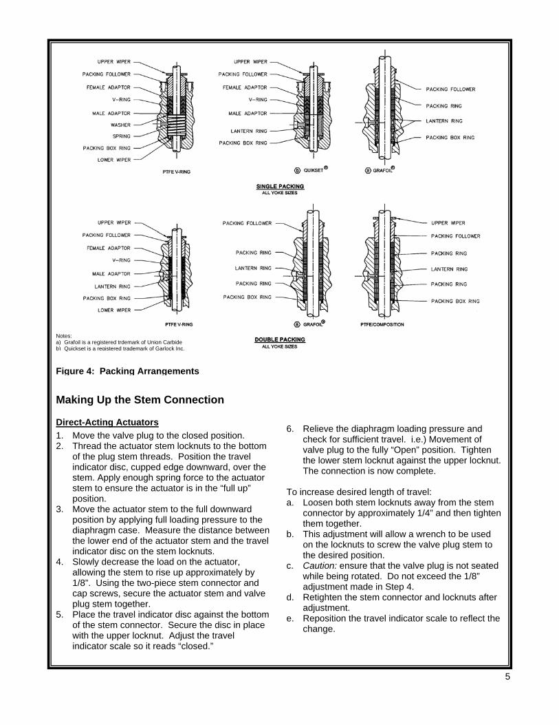
Figure 4: Packing Arrangements
Making Up the Stem Connection
Direct-Acting Actuators 1. Move the valve plug to the closed position. 2. Thread the actuator stem locknuts to the bottom
of the plug stem threads. Position the travel indicator disc, cupped edge downward, over the stem. Apply enough spring force to the actuator stem to ensure the actuator is in the “full up” position.
3. Move the actuator stem to the full downward position by applying full loading pressure to the diaphragm case. Measure the distance between the lower end of the actuator stem and the travel indicator disc on the stem locknuts.
4. Slowly decrease the load on the actuator, allowing the stem to rise up approximately by 1/8”. Using the two-piece stem connector and cap screws, secure the actuator stem and valve plug stem together.
5. Place the travel indicator disc against the bottom of the stem connector. Secure the disc in place with the upper locknut. Adjust the travel indicator scale so it reads “closed.”
6. Relieve the diaphragm loading pressure and check for sufficient travel. i.e.) Movement of valve plug to the fully “Open” position. Tighten the lower stem locknut against the upper locknut. The connection is now complete.
To increase desired length of travel: a. Loosen both stem locknuts away from the stem
connector by approximately 1/4” and then tighten them together.
b. This adjustment will allow a wrench to be used on the locknuts to screw the valve plug stem to the desired position.
c. Caution: ensure that the valve plug is not seated while being rotated. Do not exceed the 1/8” adjustment made in Step 4.
d. Retighten the stem connector and locknuts after adjustment.
e. Reposition the travel indicator scale to reflect the change.
Notes: a) Grafoil is a registered trdemark of Union Carbide b) Quickset is a registered trademark of Garlock Inc.
6
Making Up the Stem Connection
Reverse-Acting Actuators 1. Close the valve plug ensuring the valve plug is
on the seat. 2. Supply enough spring force to the actuator stem
to ensure the actuator is in full “Down” position. Increase the loading pressure to the diaphragm case to allow the actuator stem to rise sufficiently so the locknuts can be screwed onto the valve plug stem. Thread the locknuts down on the valve plug stem as far as possible. Set the travel indicator on the locknuts, “cupped” edge downward.
3. Slowly release the pressure in the diaphragm case, allowing the actuator to return to the full down position. Measure the distance between the lower end of the actuator stem and the travel indicator disc.
4. Increase the load on the actuator, causing the stem to rise up by approximately 1/8”. Using the two-piece stem connector and cap screws, secure the actuator stem and valve plug stem together.
5. Move the travel indicator disc against the bottom of the stem connector.
6. Secure the disc with the upper locknut. Change the travel indicator scale so that it reads closed.
7. Open the valve plug by increasing the diaphragm loading pressure. Secure the lower stem locknut against the upper locknut. The connection is now complete.
8. To increase travel see “To increase desired length of travel” instructions.
Parts Ordering A serial number identifies every CVS Series E valve body-bonnet assembly, which can be found on the front of the valve. Please refer to this number when contacting your CVS Controls representative.
7
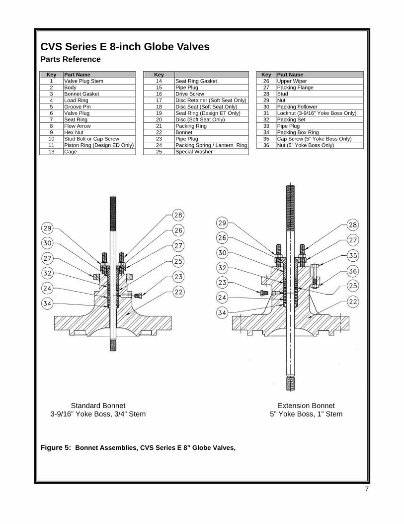
CVS Series E 8-inch Globe Valves Parts Reference
Key Part Name Key Key Part Name 1 Valve Plug Stem 14 Seat Ring Gasket 26 Upper Wiper 2 Body 15 Pipe Plug 27 Packing Flange 3 Bonnet Gasket 16 Drive Screw 28 Stud 4 Load Ring 17 Disc Retainer (Soft Seat Only) 29 Nut 5 Groove Pin 18 Disc Seat (Soft Seat Only) 30 Packing Follower 6 Valve Plug 19 Seal Ring (Design ET Only) 31 Locknut (3-9/16” Yoke Boss Only) 7 Seat Ring 20 Disc (Soft Seat Only) 32 Packing Set 8 Flow Arrow 21 Packing Ring 33 Pipe Plug 9 Hex Nut 22 Bonnet 34 Packing Box Ring
10 Stud Bolt or Cap Screw 23 Pipe Plug 35 Cap Screw (5” Yoke Boss Only) 11 Piston Ring (Design ED Only) 24 Packing Spring / Lantern Ring 36 Nut (5” Yoke Boss Only) 13 Cage 25 Special Washer
Figure 5: Bonnet Assemblies, CVS Series E 8” Globe Valves,
Standard Bonnet 3-9/16” Yoke Boss, 3/4” Stem
Extension Bonnet 5” Yoke Boss, 1” Stem
8
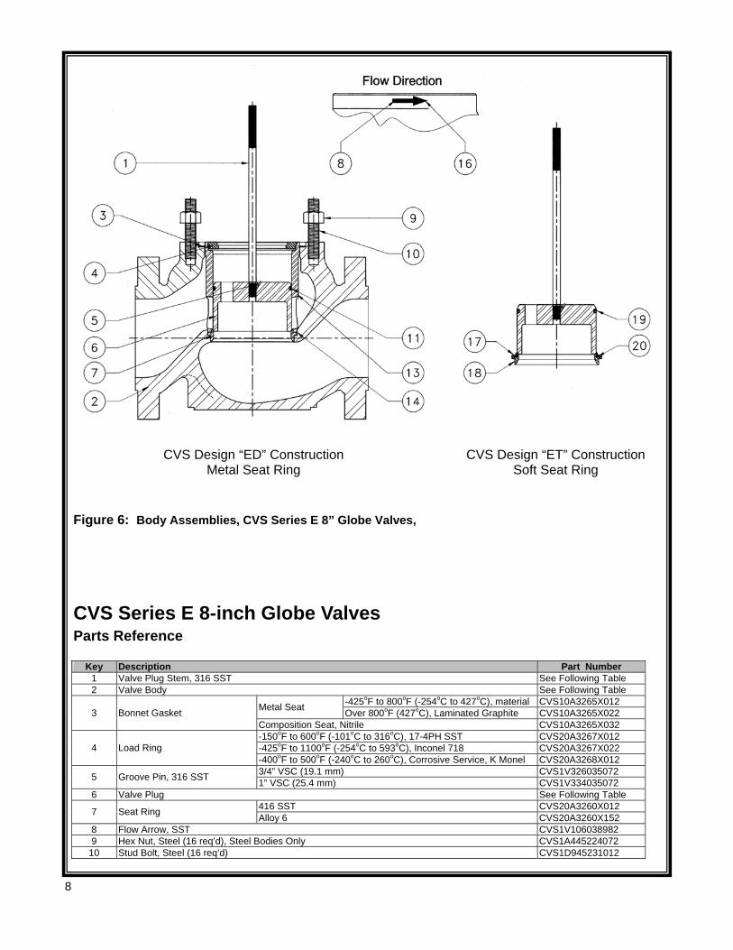
Figure 6: Body Assemblies, CVS Series E 8” Globe Valves,
CVS Design “ED” Construction Metal Seat Ring
CVS Design “ET” Construction Soft Seat Ring
CVS Series E 8-inch Globe Valves Parts Reference
Key Description Part Number 1 Valve Plug Stem, 316 SST See Following Table 2 Valve Body See Following Table
-425oF to 800oF (-254oC to 427oC), material CVS10A3265X012 Metal Seat Over 800oF (427oC), Laminated Graphite CVS10A3265X022 3 Bonnet Gasket Composition Seat, Nitrile CVS10A3265X032 -150oF to 600oF (-101oC to 316oC), 17-4PH SST CVS20A3267X012 -425oF to 1100oF (-254oC to 593oC), Inconel 718 CVS20A3267X022 4 Load Ring -400oF to 500oF (-240oC to 260oC), Corrosive Service, K Monel CVS20A3268X012 3/4” VSC (19.1 mm) CVS1V326035072 5 Groove Pin, 316 SST 1” VSC (25.4 mm) CVS1V334035072
6 Valve Plug See Following Table 416 SST CVS20A3260X012 7 Seat Ring Alloy 6 CVS20A3260X152
8 Flow Arrow, SST CVS1V106038982 9 Hex Nut, Steel (16 req’d), Steel Bodies Only CVS1A445224072
10 Stud Bolt, Steel (16 req’d) CVS1D945231012
9
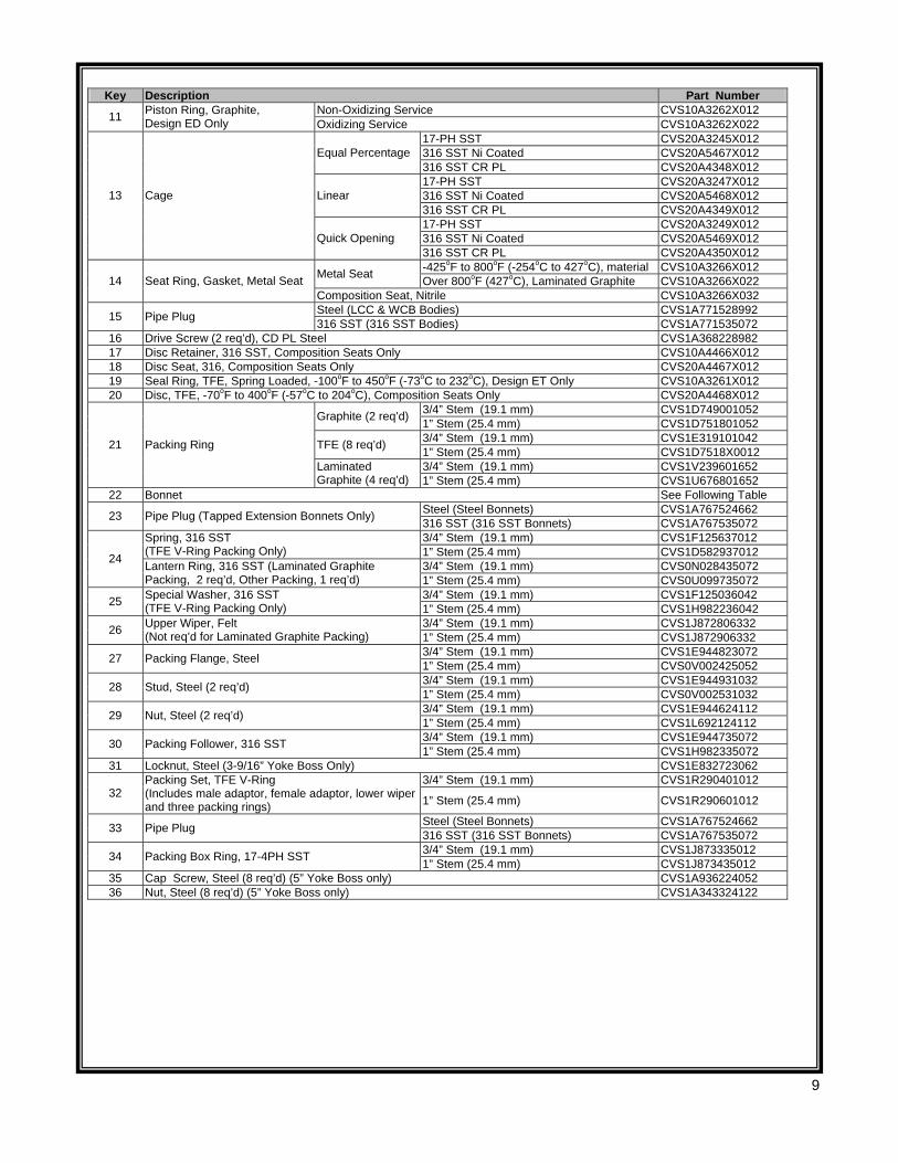
Key Description Part Number
Non-Oxidizing Service CVS10A3262X012 11 Piston Ring, Graphite, Design ED Only Oxidizing Service CVS10A3262X022
17-PH SST CVS20A3245X012 316 SST Ni Coated CVS20A5467X012 Equal Percentage 316 SST CR PL CVS20A4348X012 17-PH SST CVS20A3247X012 316 SST Ni Coated CVS20A5468X012 Linear 316 SST CR PL CVS20A4349X012 17-PH SST CVS20A3249X012 316 SST Ni Coated CVS20A5469X012
13 Cage
Quick Opening 316 SST CR PL CVS20A4350X012 -425oF to 800oF (-254oC to 427oC), material CVS10A3266X012 Metal Seat Over 800oF (427oC), Laminated Graphite CVS10A3266X022 14 Seat Ring, Gasket, Metal Seat
Composition Seat, Nitrile CVS10A3266X032 Steel (LCC & WCB Bodies) CVS1A771528992 15 Pipe Plug 316 SST (316 SST Bodies) CVS1A771535072
16 Drive Screw (2 req’d), CD PL Steel CVS1A368228982 17 Disc Retainer, 316 SST, Composition Seats Only CVS10A4466X012 18 Disc Seat, 316, Composition Seats Only CVS20A4467X012 19 Seal Ring, TFE, Spring Loaded, -100oF to 450oF (-73oC to 232oC), Design ET Only CVS10A3261X012 20 Disc, TFE, -70oF to 400oF (-57oC to 204oC), Composition Seats Only CVS20A4468X012
3/4” Stem (19.1 mm) CVS1D749001052 Graphite (2 req’d) 1” Stem (25.4 mm) CVS1D751801052 3/4” Stem (19.1 mm) CVS1E319101042 TFE (8 req’d) 1” Stem (25.4 mm) CVS1D7518X0012 3/4” Stem (19.1 mm) CVS1V239601652
21 Packing Ring
Laminated Graphite (4 req’d) 1” Stem (25.4 mm) CVS1U676801652
22 Bonnet See Following Table Steel (Steel Bonnets) CVS1A767524662 23 Pipe Plug (Tapped Extension Bonnets Only) 316 SST (316 SST Bonnets) CVS1A767535072 3/4” Stem (19.1 mm) CVS1F125637012 Spring, 316 SST
(TFE V-Ring Packing Only) 1” Stem (25.4 mm) CVS1D582937012 3/4” Stem (19.1 mm) CVS0N028435072 24 Lantern Ring, 316 SST (Laminated Graphite
Packing, 2 req’d, Other Packing, 1 req’d) 1” Stem (25.4 mm) CVS0U099735072 3/4” Stem (19.1 mm) CVS1F125036042 25 Special Washer, 316 SST
(TFE V-Ring Packing Only) 1” Stem (25.4 mm) CVS1H982236042 3/4” Stem (19.1 mm) CVS1J872806332 26 Upper Wiper, Felt
(Not req’d for Laminated Graphite Packing) 1” Stem (25.4 mm) CVS1J872906332 3/4” Stem (19.1 mm) CVS1E944823072 27 Packing Flange, Steel 1” Stem (25.4 mm) CVS0V002425052 3/4” Stem (19.1 mm) CVS1E944931032 28 Stud, Steel (2 req’d) 1” Stem (25.4 mm) CVS0V002531032 3/4” Stem (19.1 mm) CVS1E944624112 29 Nut, Steel (2 req’d) 1” Stem (25.4 mm) CVS1L692124112 3/4” Stem (19.1 mm) CVS1E944735072 30 Packing Follower, 316 SST 1” Stem (25.4 mm) CVS1H982335072
31 Locknut, Steel (3-9/16” Yoke Boss Only) CVS1E832723062 3/4” Stem (19.1 mm) CVS1R290401012
32 Packing Set, TFE V-Ring (Includes male adaptor, female adaptor, lower wiper and three packing rings) 1” Stem (25.4 mm) CVS1R290601012
Steel (Steel Bonnets) CVS1A767524662 33 Pipe Plug 316 SST (316 SST Bonnets) CVS1A767535072 3/4” Stem (19.1 mm) CVS1J873335012 34 Packing Box Ring, 17-4PH SST 1” Stem (25.4 mm) CVS1J873435012
35 Cap Screw, Steel (8 req’d) (5” Yoke Boss only) CVS1A936224052 36 Nut, Steel (8 req’d) (5” Yoke Boss only) CVS1A343324122
10
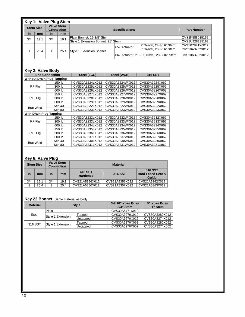
Key 1: Valve Plug Stem Stem Size Valve Stem
Connection In mm In mm
Specifications Part Number
Plain Bonnet, 19-3/8” Stem CVS1K588035162 3/4 19.1 3/4 19.1 Style 1 Extension Bonnet, 21” Stem CVS1U928235162 2” Travel, 24-3/16” Stem CVS1K7891X0012 657 Actuator 3” Travel, 23-3/16” Stem CVS10A3282X012 1 25.4 1 25.4 Style 1 Extension Bonnet
667 Actuator, 2” – 3” Travel, 23-3/16” Stem CVS10A3282X012
Key 2: Valve Body
End Connection Steel (LCC) Steel (WCB) 316 SST Without Drain Plug Tapping
150 lb CVS30A3224LX012 CVS30A3224WX012 CVS30A3224X062 300 lb CVS30A3225LX012 CVS30A3225WX012 CVS30A3225X062 RF Flg 600 lb CVS30A3226LX012 CVS30A3226WX012 CVS30A3226X062 150 lb CVS30A3227LX012 CVS30A3227WX012 CVS30A3227X062 300 lb CVS30A3228LX012 CVS30A3228WX012 CVS30A3228X062 RTJ Flg 600 lb CVS30A3229LX012 CVS30A3229WX012 CVS30A3229X062 Sch 40 CVS30A3222LX012 CVS30A3222WX012 CVS30A3222X062 Butt Weld Sch 80 CVS30A3223LX012 CVS30A3223WX012 CVS30A3223X062
With Drain Plug Tapping 150 lb CVS30A3232LX012 CVS30A3232WX012 CVS30A3232X062 300 lb CVS30A3233LX012 CVS30A3233WX012 CVS30A3233X062 RF Flg 600 lb CVS30A3234LX012 CVS30A3234WX012 CVS30A3234X062 150 lb CVS30A3235LX012 CVS30A3235WX012 CVS30A3235X062 300 lb CVS30A3236LX012 CVS30A3236WX012 CVS30A3236X062 RTJ Flg 600 lb CVS30A3237LX012 CVS30A3237WX012 CVS30A3237X062 Sch 40 CVS30A3230LX012 CVS30A3230WX012 CVS30A3230X062 Butt Weld Sch 80 CVS30A3231LX012 CVS30A3231WX012 CVS30A3231X062
Key 6: Valve Plug
Stem Size Valve Stem Connection Material
In mm In mm 416 SST Hardened 316 SST
316 SST Hard Faced Seat &
Guide 3/4 19.1 3/4 19.1 CVS21A5356X012 CVS21A5356X022 CVS21A5362X012 1 25.4 1 25.4 CVS21A5356X012 CVS21A5357X022 CVS21A5363X012
Key 22 Bonnet, Same material as body
Material Style 3-9/16” Yoke Boss 3/4” Stem
5” Yoke Boss 1” Stem
Plain CVS30A5471X012 --- Tapped CVS30A3279X012 CVS30A3280X012 Steel Style 1 Extension Untapped CVS30A3270X012 CVS30A3274X012 Tapped CVS30A3279X062 CVS30A3280X062 316 SST Style 1 Extension Untapped CVS30A3270X062 CVS30A3274X062
11
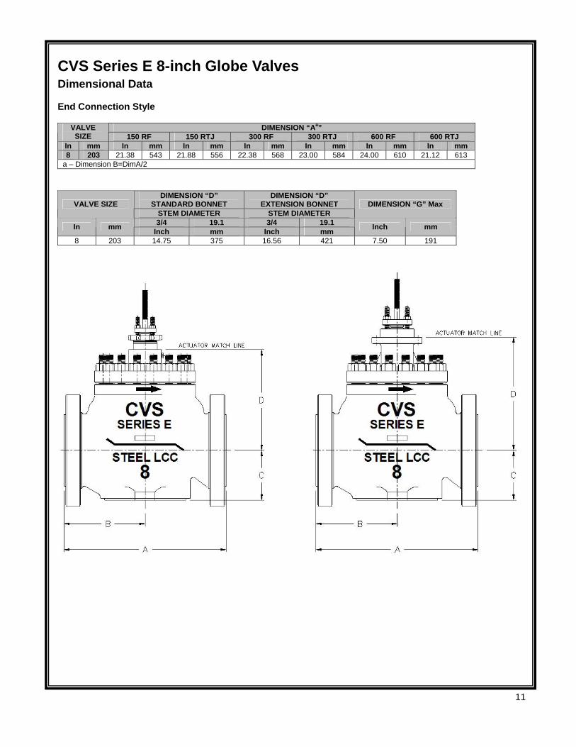
CVS Series E 8-inch Globe Valves Dimensional Data End Connection Style
DIMENSION “Aa” VALVE SIZE 150 RF 150 RTJ 300 RF 300 RTJ 600 RF 600 RTJ
In mm In mm In mm In mm In mm In mm In mm 8 203 21.38 543 21.88 556 22.38 568 23.00 584 24.00 610 21.12 613
a – Dimension B=DimA/2
DIMENSION “D” STANDARD BONNET
DIMENSION “D” EXTENSION BONNET VALVE SIZE
STEM DIAMETER STEM DIAMETER DIMENSION “G” Max
3/4 19.1 3/4 19.1 In mm Inch mm Inch mm Inch mm
8 203 14.75 375 16.56 421 7.50 191
12
Rev 0 01/04 Printed in Canada
Head Office 3900 – 101 Street
Edmonton, Alberta, Canada T6E 0A5 Office: (780) 437-3055 Fax: (780) 436-5461
Website: www.cvs-controls.com E-Mail: [email protected]
Calgary Sales Office 205, 2323 – 32 Avenue NE
Calgary, Alberta, Canada T2E 6Z3 Office: (403) 250-1416 Fax: (403) 291-9487