Embed Size (px)
Citation preview
CVS Series E 1 through 6-Inch Globe
Valves Design “ED” and “ET”
Introduction Contents Contained in this manual are installation instructions, maintenance procedures and parts information for the 1 through 6-inch CVS Series E, Design ED and ET Globe Valves. Refer to the appropriate manuals for instructions for the accompanying actuator and additional accessories.
Trained or experienced personnel should carry out operation and installation of all pressure equipment. If you have any questions regarding the equipment, contact your CVS Controls representative.
Applications and Features The CVS Series E is a single port, globe-style body with composition or metal seats and a balanced push-down-to-close valve action plug.
There are two styles of valve available, providing excellent pressure and flow control on steam, gasses and various liquid applications: 1. Design ED is intended for general control
applications over a wide variety of temperaturesand pressure drops. This design has an upperpiston ring seal and metal-to-metal seating.
2. Design ET is intended for applications requiringlow leakage rates with composition seating(TFE) for tight shutoff requirements or metal-to-metal seating for higher temperature capabilities.The valve plug has a two-piece upper seal.
Instruction Manual
Figure 1: CVS Series E Valve
For standard cages the flow direction is flow-down. The following flow characteristics are available: linear, quick opening and equal percent.
The end connections are ANSI Class 150, 300 and 600 Raised Face, or Ring Type Joint flanges as per ASME B16.34-latest edition.
Head Office 3900 – 101 Street Edmonton, Alberta, Canada T6E 0A5 Office: (780) 437-3055 Fax: (780) 436-5461
Website: www.cvs-controls.com E-Mail: [email protected]
Calgary Sales Office 3516 114 Avenue SE
Calgary, Alberta, Canada T2Z3V6 Office: (403) 250-1416
Fax: (403) 291-9487
CVS Series E Globe Valve are available in the following body materials - LCC, WCB, WCC, WC9, C5, Monel, and CF8M SST. Additional materials may be available upon request.
Trim material is available in 316SST, 416SST, 17-4PH, Alloy6-Co.Cr-A, Cobalt and316SST/Tungsten Carbide.
Sour Service Capability
Optional NACE MRO175/ISO 15156-2009
1
Installation 1. Before installing a CVS Series E valve carefully
inspect for damage that may have occurred inshipment.
2. Remove all welding slag, pipe scale and anyother foreign matter by cleaning out the linesbefore installation.
3. Install the valve so that the flow direction arrowon the body coincides with the actual process flow through the valve.
4. Use accepted piping practices when installing the valve. Use a suitable gasket between pipeline flanges and valve body.
5. Although the control valve can be installed in anyposition, the typical installation has the actuatorvertical above the body.
6. Installing a conventional 3-valve bypass aroundthe body will allow for continuous operationduring maintenance and inspection.
7. CVS Series E valve bodies are rated at 150, 300and 600 lb. ANSI. Be sure not to install the valvein any system where working pressures aregreater than those specified in the standards.
Valve Size, Inches
Weight Lbs Kg
1, 1-1/4 30 14 1-1/2 45 20
2 68 31 2-1/2 100 45
3 125 57 4 170 78 6 350 160
Table 1: Approximate Weights
Maintenance
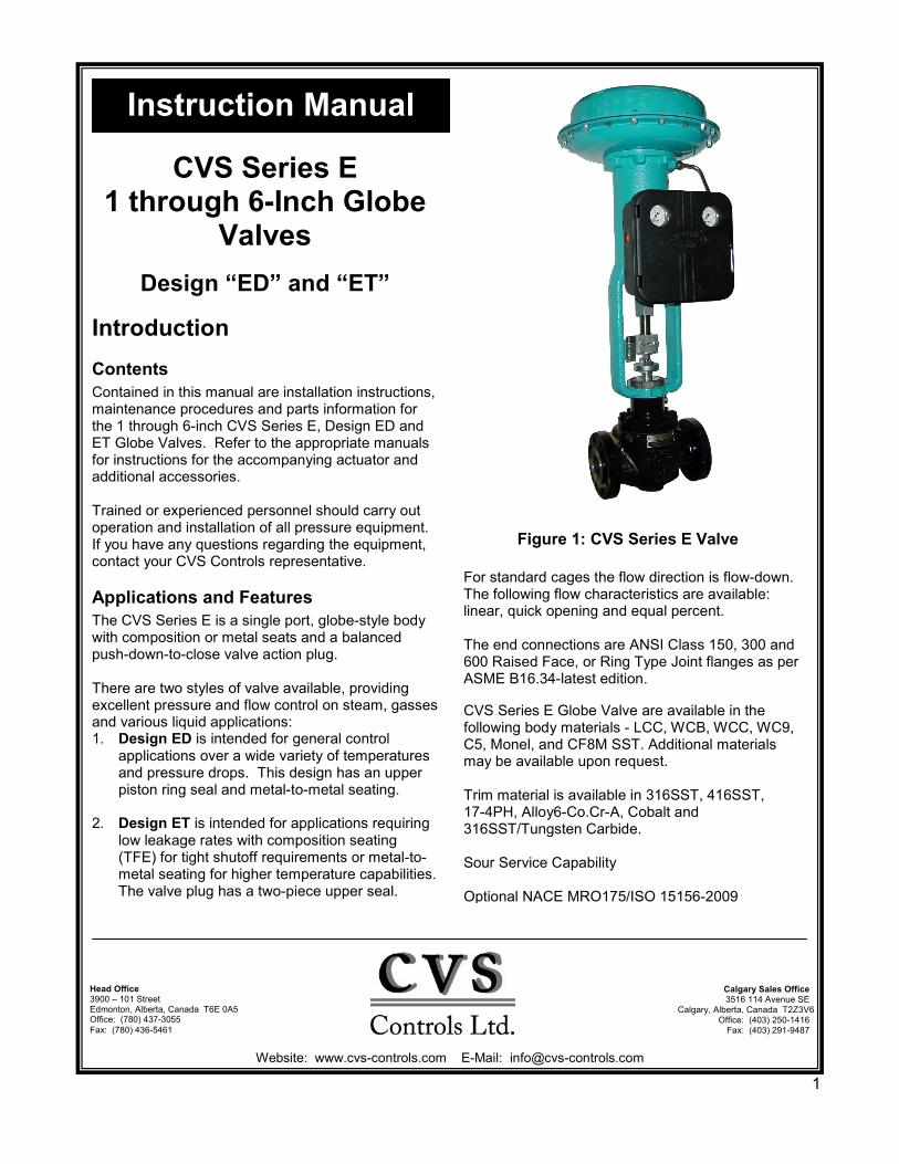
Warning: To avoid damage to the process system or personal injury, isolate the valve from the system and relieve any pressure contained within prior to disassembly. Disconnect any operating lines providing air pressure, control signals or electrical power to the actuator.
2
Disassembly Except where indicated, refer to Figure 2 for part descriptions used in the following procedure.
1. With the actuator disconnected and removedfrom the body, remove the hex nuts, (key 15,figure 9).
2. Remove the bonnet with the valve plug andstem.
3. Loosen the packing flange nuts (key 5, figure 8)and remove the valve plug and stem from thebonnet. If the valve stem needs replacement,punch out the groove pin and unscrew the stem.If the valve plug needs replacement, a new valveplug and stem assembly is required.
Warning: Do not use an old stem with a newvalve plug. Using an old stem requires drilling anew hole for the groove pin and as a result, theintegrity of the stem is weakened.
4. If desired you may disassemble the internal partsof the bonnet. To replace the Packing, seeinstructions titled “Packing Replacement” in thismanual.
Warning: The portion of the cage which isexposed provides a guiding surface. Ensure thatthis surface is not damaged during disassemblyor maintenance. If the cage is seized in the body,use a rubber mallet to strike the exposed portionat varying points around its circumference.
5. Remove the cage and gaskets from the valvebody. With restricted trim, (figure 11) remove theseat ring adaptor (key 5) and the cage adaptor(key 4).
6. Remove the seat ring and its gasket. Withcomposition seats, remove the disc retainer, discseat and TFE disc.
Reassembly Except where indicated refer to Figure 2 for part descriptions used in the following procedure.
1. Clean all gasket-seating surfaces. Use newgaskets only for reassembly.
2. With restricted trim (figure 11) install the seatring adaptor gasket (key 13) and the adaptor(key 5).
3. Replace the seat ring gasket (key 12) and installthe seat ring (key 8). If using a composition seat,assemble it by placing the TFE disc (key 20) intothe disc retainer (key 18), then sliding thisassembly over the disc seat (key 19).
4. Place the cage (key 3) onto the seat ring (key 9).Any rotational orientation of the cage withrespect to the valve body is acceptable.
5. With full-sized trim, install cage gasket (key 10),spiral wound gasket (key 11) and bonnet gasket(key 9) onto the cage shoulder.
6. With restricted trim, install the cage gasket (key10), spiral wound gasket (key 11) and anadditional cage gasket (key 10) onto the cageshoulder. Install the cage adaptor and place thebonnet gasket onto the adaptor.
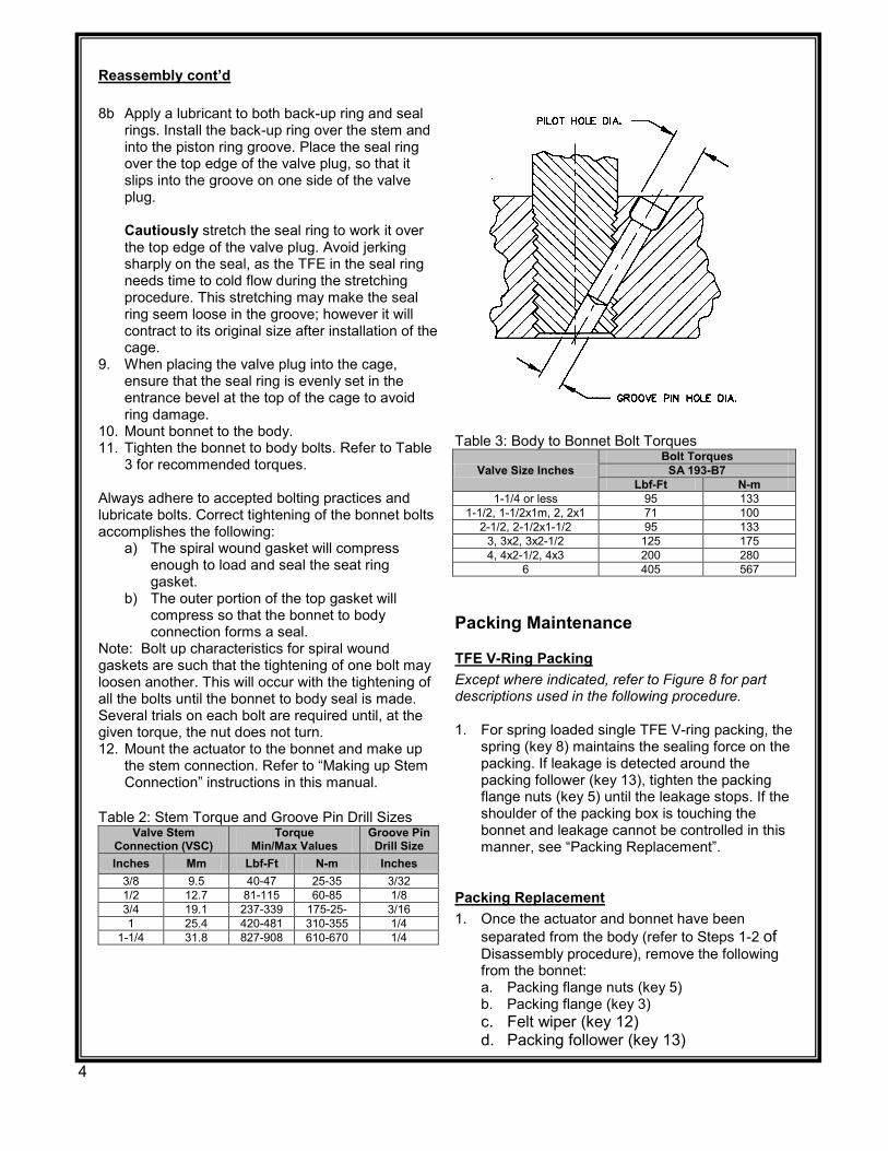
7. If installing a new stem in the valve plug, screwthe new stem into the valve plug. Refer to Table2 for appropriate torque values and drill sizes.Drill through the stem, using the hole in the valveplug as a guide. Remove any chips or burrs anddrive in a new groove pin to lock the assembly.
8. If the seal ring appears damaged, remove andreplace with a new one. Be careful not to scratchthe ring groove surfaces. Damage to the ringgroove surface may prevent the new ring fromsealing properly. The seal ring must either bepried or cut from the groove and thereforecannot be reused.
If possible, lapping of metal seats should bedone before seal ring installation. Refer to the“Lapping Metal Seats” procedure in this manual.
8a For valve bodies using a carbon-filled TFE piston ring, locate the split and slightly spread the ring. Install the ring over the stem and onto the piston ring groove on the valve plug. Graphite piston rings are supplied as a complete ring and must be broken into two sections. The piston ring can be broken in half by scoring, and then breaking over a hard surface such as the edge of a table. Ensure the broken ends are re-matched when the piston ring is installed in the piston ring groove.
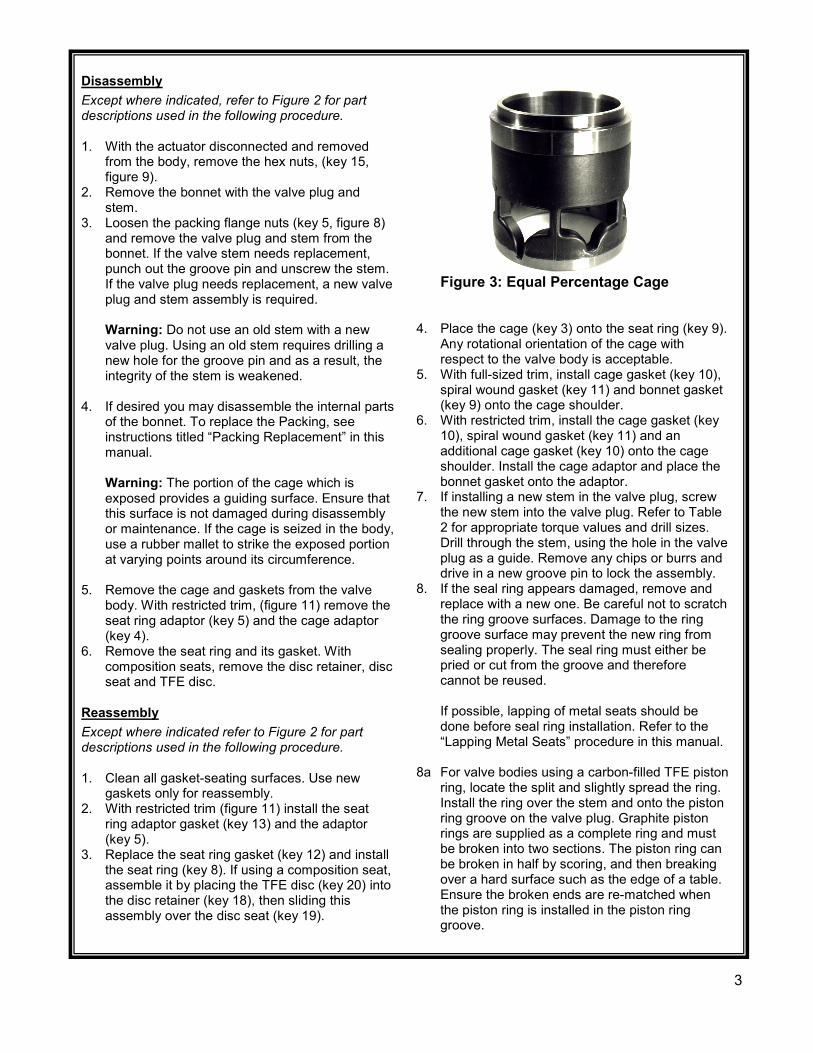
Figure 3: Equal Percentage Cage
3
Reassembly cont’d 8b Apply a lubricant to both back-up ring and seal
rings. Install the back-up ring over the stem and into the piston ring groove. Place the seal ring over the top edge of the valve plug, so that it slips into the groove on one side of the valve plug.
Cautiously stretch the seal ring to work it over
the top edge of the valve plug. Avoid jerking sharply on the seal, as the TFE in the seal ring needs time to cold flow during the stretching procedure. This stretching may make the seal ring seem loose in the groove; however it will contract to its original size after installation of the cage.
9. When placing the valve plug into the cage, ensure that the seal ring is evenly set in the entrance bevel at the top of the cage to avoid ring damage.
10. Mount bonnet to the body. 11. Tighten the bonnet to body bolts. Refer to Table
3 for recommended torques. Always adhere to accepted bolting practices and lubricate bolts. Correct tightening of the bonnet bolts accomplishes the following:
a) The spiral wound gasket will compress enough to load and seal the seat ring gasket.
b) The outer portion of the top gasket will compress so that the bonnet to body connection forms a seal.
Note: Bolt up characteristics for spiral wound gaskets are such that the tightening of one bolt may loosen another. This will occur with the tightening of all the bolts until the bonnet to body seal is made. Several trials on each bolt are required until, at the given torque, the nut does not turn. 12. Mount the actuator to the bonnet and make up
the stem connection. Refer to “Making up Stem Connection” instructions in this manual.
Table 2: Stem Torque and Groove Pin Drill Sizes
Valve Stem Connection (VSC)
Torque Min/Max Values
Groove Pin Drill Size
Inches Mm Lbf-Ft N-m Inches 3/8 9.5 40-47 25-35 3/32 1/2 12.7 81-115 60-85 1/8 3/4 19.1 237-339 175-25- 3/16 1 25.4 420-481 310-355 1/4
1-1/4 31.8 827-908 610-670 1/4
Table 3: Body to Bonnet Bolt Torques
Valve Size Inches Bolt Torques
SA 193-B7 Lbf-Ft N-m
1-1/4 or less 95 133 1-1/2, 1-1/2x1m, 2, 2x1 71 100
2-1/2, 2-1/2x1-1/2 95 133 3, 3x2, 3x2-1/2 125 175 4, 4x2-1/2, 4x3 200 280
6 405 567
Packing Maintenance
TFE V-Ring Packing Except where indicated, refer to Figure 8 for part descriptions used in the following procedure. 1. For spring loaded single TFE V-ring packing, the
spring (key 8) maintains the sealing force on the packing. If leakage is detected around the packing follower (key 13), tighten the packing flange nuts (key 5) until the leakage stops. If the shoulder of the packing box is touching the bonnet and leakage cannot be controlled in this manner, see “Packing Replacement”.
Packing Replacement 1. Once the actuator and bonnet have been
separated from the body (refer to Steps 1-2 of Disassembly procedure), remove the following from the bonnet: a. Packing flange nuts (key 5) b. Packing flange (key 3) c. Felt wiper (key 12) d. Packing follower (key 13)
4
Packing Replacement cont’d 2. Clean the packing box bore, spring (key 8),
washer (key 10), and the packing box ring (key11).
3. Install the valve plug assembly and mount thebonnet to the body using new gaskets. Use thesequence shown in Figure 4 to install newpacking and associated parts. Be sure not todamage the packing during installation. Replacethe packing flange (key 3), tighten the packingflange nuts (key 5) until the shoulder of thepacking follower (key 13) is approximately 5/8”from the top of the bonnet. If leakage is detectedaround the packing follower, tighten the packingflange nuts until the leakage stops.
4. For graphite packing, tighten the packing flangenuts to the maximum torque value in Table 4.Then back off the nuts and retighten them to theminimum torque value in Table 4.
5. For other Packing Types, in small equalincrements, tighten the flange nuts until one ofthe nuts reach the minimum torque shown inTable 4. Then, tighten the other nut until thepacking flange is level.
6. Mount the actuator and set the stem connectorto the required travel. Refer to “Making Up StemConnection” procedure.
Packing Lubrication The use of semi-metallic packing requires the use of a lubricator or lubricator/isolating valve (figure 5). The lubricator or lubricator/isolating valve is mounted in place of a pipe plug (key 14, figure 7, 8). For standard service up to 450oF, use Dow Corning lubricant or equivalent.
Lubricator: To add lubricant to the packing box, turn the cap screw in a clockwise direction.
Lubricator/Isolating Valve: Open the isolating valve, turn the cap screw in a clockwise direction, then close the isolating valve.
Lapping Metal Seats In any valve body, a certain amount of leakage should be expected with metal-to-metal seating. However, if the leakage becomes excessive, lapping can enhance the condition of the seating surfaces of the valve plug and seat ring. Deep nicks in the seating surface should be removed by machining rather than lapping. There are many lapping compounds available commercially. Be sure to use one of high quality. Apply lapping compound to the bottom of the plug.
In order to position the cage and seat ring properly and to help align the valve plug with the seat ring, bolt the bonnet to the body with gaskets (the old gaskets can be used) in place during the lapping procedure. A simple handle can be made from a piece of metal secured to the valve stem with nuts. Rotate the handle in opposite directions to lap the seating surfaces. Once lapping is complete, disconnect the bonnet, clean the seating surfaces, reassemble and then test for shutoff. If leakage is still excessive, repeat the lapping procedure.
Table 4: Torque Values for Packing Flange Nuts
Valve Stem Diameter ANSI Rating
PTFE Type Packing Graphite Type Packing
Inches Mm Min. Torque Max. Torque Min. Torque Max. Torque Lbf-in N-m Lbf-in N-m Lbf-in N-m Lbf-in N-m
3/8 9.5 150 13 1 19 2 27 3 40 5 300 17 2 26 3 36 4 53 6 600 23 3 35 4 49 6 73 8
1/2 12.7 150 21 2 31 4 44 5 66 8 300 28 3 42 5 59 7 88 10 600 39 4 58 7 81 9 122 14
3/4 19.1 150 47 5 70 8 99 11 149 17 300 64 7 95 11 133 15 199 23 600 87 10 131 15 182 21 274 31
1 25.4 300 108 12 162 18 226 26 339 38 600 149 17 223 25 310 35 466 53
1-1/4 31.8 300 152 17 228 26 318 36 477 54 600 209 24 314 36 437 49 655 74
5
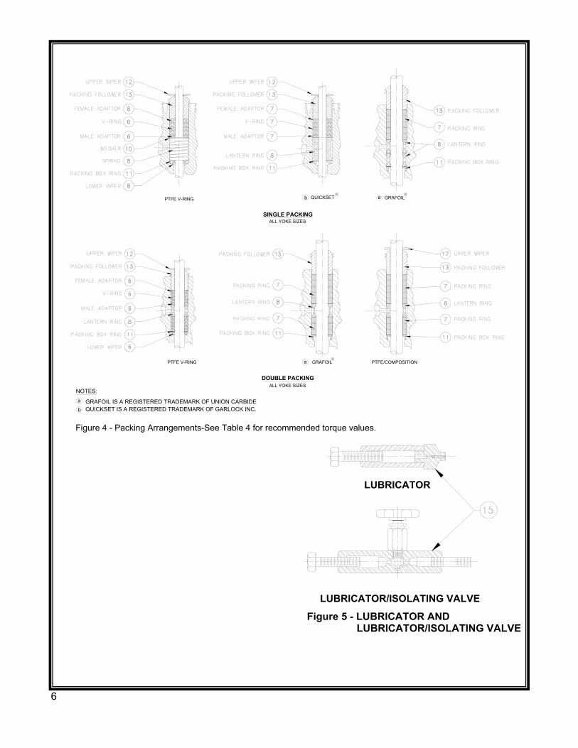
LUBRICATOR
LUBRICATOR/ISOLATING VALVE
Figure 5 - LUBRICATOR AND LUBRICATOR/ISOLATING VALVE
ALL YOKE SIZES
ALL YOKE SIZES
ab
aR
GRAFOIL
R
QUICKSETR
b
a
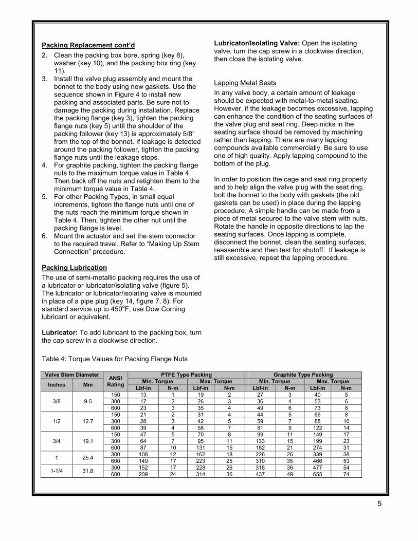
NOTES:
GRAFOIL IS A REGISTERED TRADEMARK OF UNION CARBIDE
PTFE V-RING
SINGLE PACKING
GRAFOIL
PTFE V-RING
Figure 4 - Packing Arrangements-See Table 4 for recommended torque values.
PTFE/COMPOSITION
DOUBLE PACKING
QUICKSET IS A REGISTERED TRADEMARK OF GARLOCK INC.
6
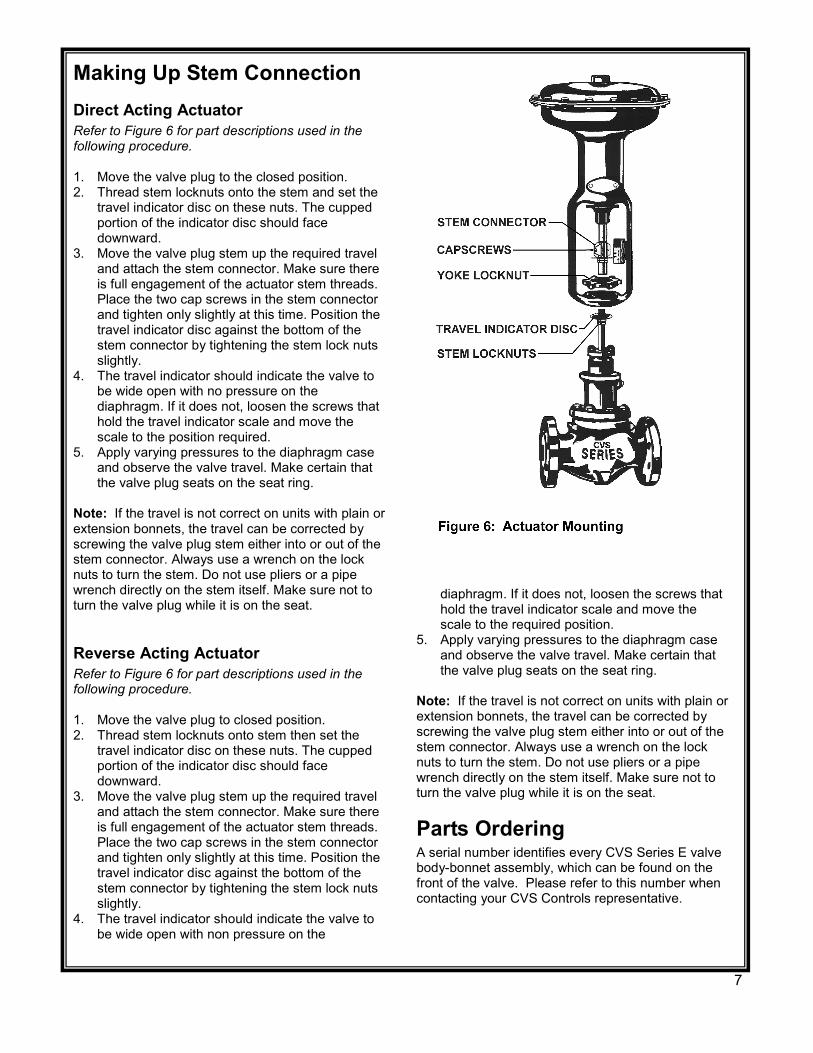
Making Up Stem Connection Direct Acting Actuator Refer to Figure 6 for part descriptions used in the following procedure. 1. Move the valve plug to the closed position. 2. Thread stem locknuts onto the stem and set the
travel indicator disc on these nuts. The cupped portion of the indicator disc should face downward.
3. Move the valve plug stem up the required travel and attach the stem connector. Make sure there is full engagement of the actuator stem threads. Place the two cap screws in the stem connector and tighten only slightly at this time. Position the travel indicator disc against the bottom of the stem connector by tightening the stem lock nuts slightly.
4. The travel indicator should indicate the valve to be wide open with no pressure on the diaphragm. If it does not, loosen the screws that hold the travel indicator scale and move the scale to the position required.
5. Apply varying pressures to the diaphragm case and observe the valve travel. Make certain that the valve plug seats on the seat ring.
Note: If the travel is not correct on units with plain or extension bonnets, the travel can be corrected by screwing the valve plug stem either into or out of the stem connector. Always use a wrench on the lock nuts to turn the stem. Do not use pliers or a pipe wrench directly on the stem itself. Make sure not to turn the valve plug while it is on the seat.
Reverse Acting Actuator Refer to Figure 6 for part descriptions used in the following procedure. 1. Move the valve plug to closed position. 2. Thread stem locknuts onto stem then set the
travel indicator disc on these nuts. The cupped portion of the indicator disc should face downward.
3. Move the valve plug stem up the required travel and attach the stem connector. Make sure there is full engagement of the actuator stem threads. Place the two cap screws in the stem connector and tighten only slightly at this time. Position the travel indicator disc against the bottom of the stem connector by tightening the stem lock nuts slightly.
4. The travel indicator should indicate the valve to be wide open with non pressure on the
diaphragm. If it does not, loosen the screws that hold the travel indicator scale and move the scale to the required position.
5. Apply varying pressures to the diaphragm case and observe the valve travel. Make certain that the valve plug seats on the seat ring.
Note: If the travel is not correct on units with plain or extension bonnets, the travel can be corrected by screwing the valve plug stem either into or out of the stem connector. Always use a wrench on the lock nuts to turn the stem. Do not use pliers or a pipe wrench directly on the stem itself. Make sure not to turn the valve plug while it is on the seat.
Parts Ordering A serial number identifies every CVS Series E valve body-bonnet assembly, which can be found on the front of the valve. Please refer to this number when contacting your CVS Controls representative.
7
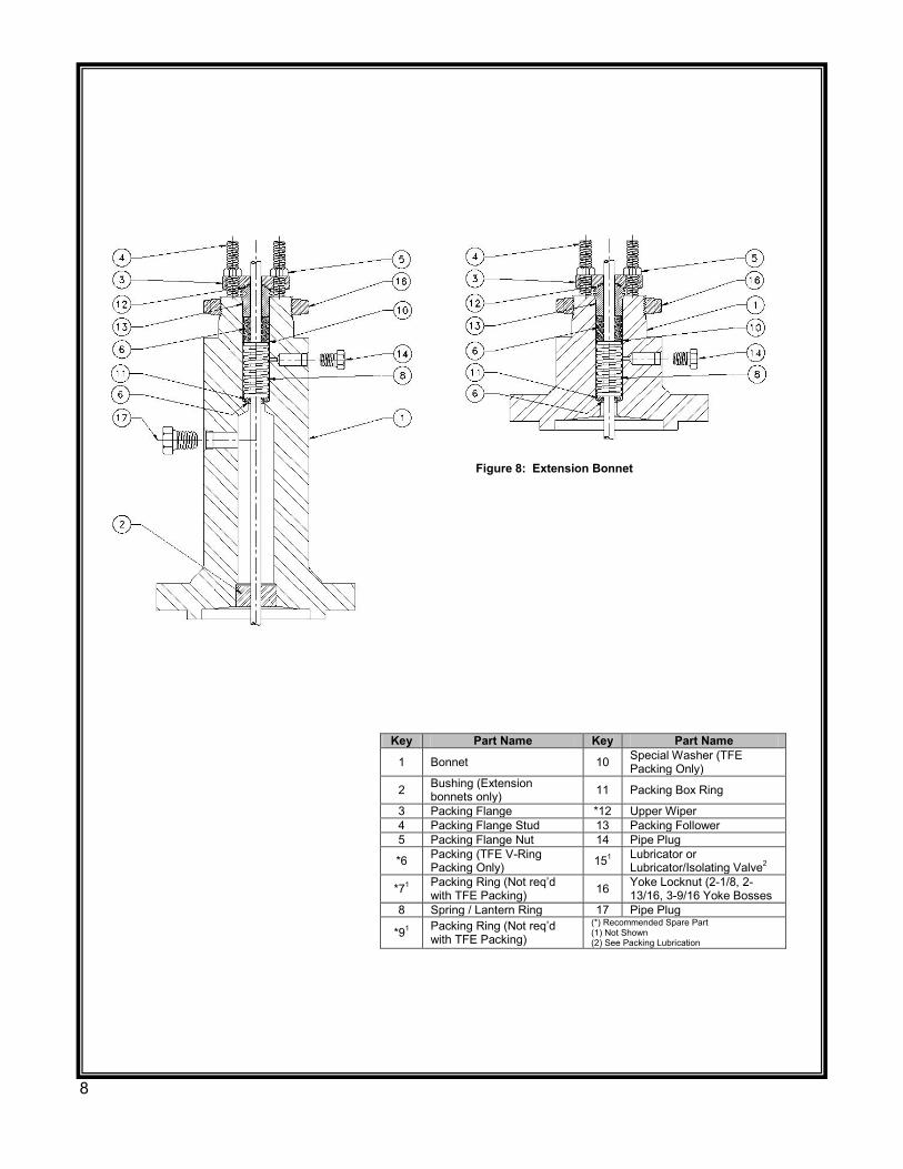
Key Part Name Key Part Name
1 Bonnet 10 Special Washer (TFE Packing Only)
2 Bushing (Extension bonnets only) 11 Packing Box Ring
3 Packing Flange *12 Upper Wiper 4 Packing Flange Stud 13 Packing Follower 5 Packing Flange Nut 14 Pipe Plug
*6 Packing (TFE V-Ring Packing Only) 151 Lubricator or
Lubricator/Isolating Valve2
*71 Packing Ring (Not req’d with TFE Packing) 16 Yoke Locknut (2-1/8, 2-
13/16, 3-9/16 Yoke Bosses 8 Spring / Lantern Ring 17 Pipe Plug
*91 Packing Ring (Not req’d with TFE Packing)
(*) Recommended Spare Part (1) Not Shown (2) See Packing Lubrication
Figure 8: Extension Bonnet
8
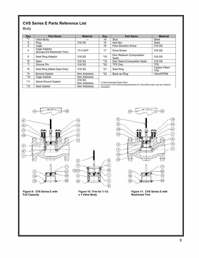
CVS Series E Parts Reference List Body
Key Part Name Material Key Part Name Material A1 Valve Body --- 14 Stud Steel *2 Plug 316 SS 15 Hex Nut Steel 3 Cage 16 Flow Direction Arrow 316 SS
4 Cage Adaptor (Except 6/4 Restricted Trim) 17-4 DHT 17 Drive Screw 316 SS
5 Seat Ring Adaptor 316 SS *18 Disc Retainer (Composition Seat) 316 SS
*6 Stem 316 SS *19 Disc Seat (Composition Seat) 316 SS *7 Groove Pin 316 SS *20 TFE Disc TFE
*8 Seat Ring (Metal Seat Only) 316 SS *21 Seal Ring Carbon Filled TFE
*9 Bonnet Gasket Non Asbestos *22 Back-up Ring Viton/EPDM *10 Cage Gasket Non Asbestos
(*) Recommended Spare Parts (A)-Consult CVS Controls Representative for Valve Body style, size and material availability
*11 Spiral Wound Gasket 316 SS Non Asbestos
*12 Seat Gasket Non Asbestos
Figure 9: CVS Series E with Full Capacity
Figure 10: Trim for 1-1/2 x 1 Valve Body
Figure 11: CVS Series E with Restricted Trim
9
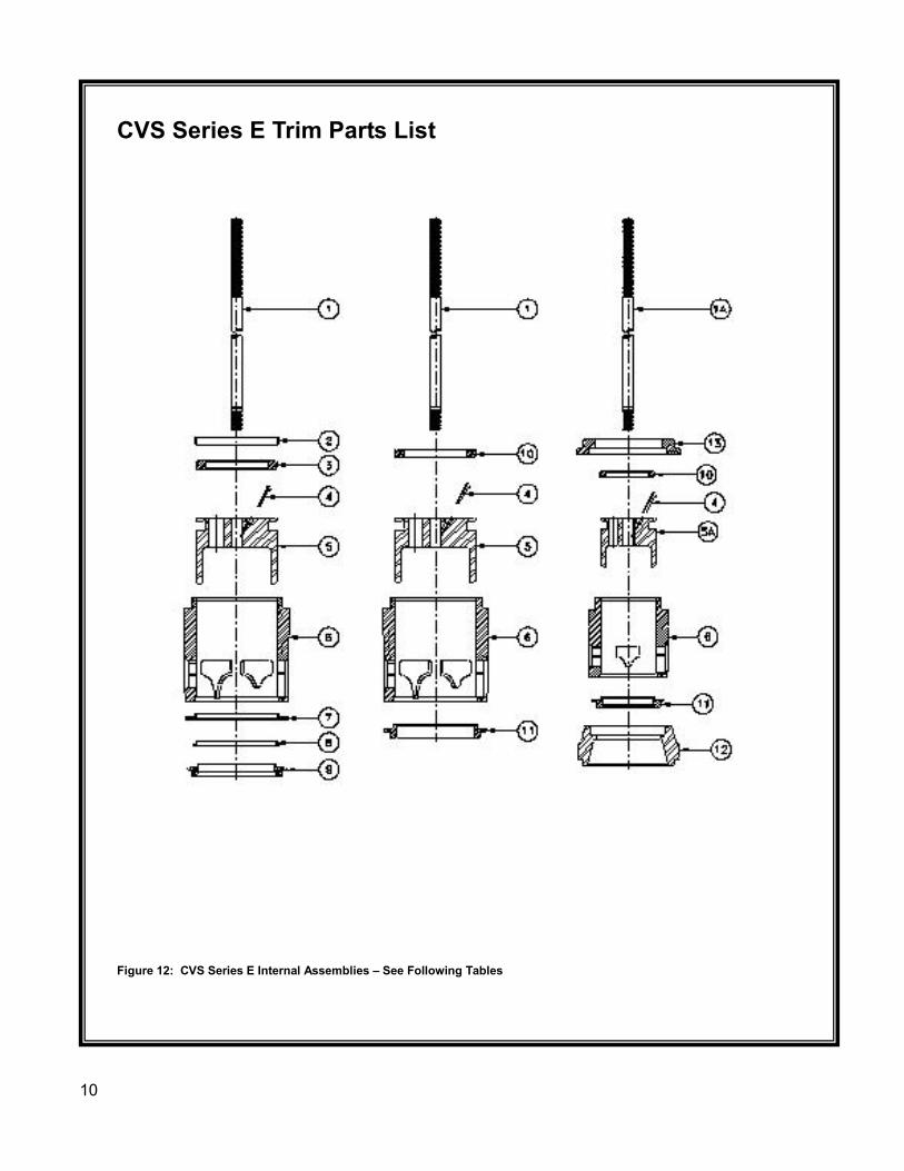
CVS Series E Trim Parts List
Figure 12: CVS Series E Internal Assemblies – See Following Tables
10
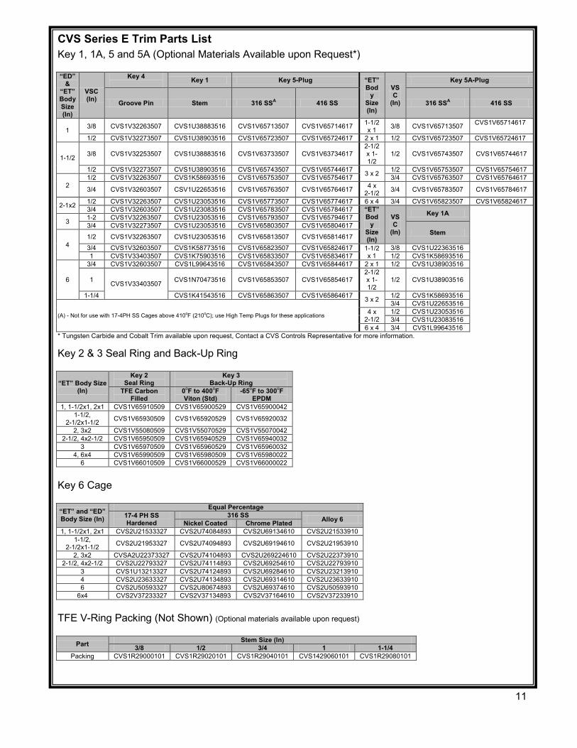
CVS Series E Trim Parts List Key 1, 1A, 5 and 5A (Optional Materials Available upon Request*)
“ED” &
“ET” Body Size (In)
VSC (In)
Key 4 Key 1 Key 5-Plug “ET” Bod
y Size (In)
VSC
(In)
Key 5A-Plug
Groove Pin Stem 316 SSA 416 SS 316 SSA 416 SS
1 3/8 CVS1V32263507 CVS1U38883516 CVS1V65713507 CVS1V65714617 1-1/2 x 1 3/8 CVS1V65713507 CVS1V65714617
1/2 CVS1V32273507 CVS1U38903516 CVS1V65723507 CVS1V65724617 2 x 1 1/2 CVS1V65723507 CVS1V65724617
1-1/2 3/8 CVS1V32253507 CVS1U38883516 CVS1V63733507 CVS1V63734617 2-1/2 x 1-1/2
1/2 CVS1V65743507 CVS1V65744617
1/2 CVS1V32273507 CVS1U38903516 CVS1V65743507 CVS1V65744617 3 x 2 1/2 CVS1V65753507 CVS1V65754617
2 1/2 CVS1V32263507 CVS1K58693516 CVS1V65753507 CVS1V65754617 3/4 CVS1V65763507 CVS1V65764617
3/4 CVS1V32603507 CSV1U22653516 CVS1V65763507 CVS1V65764617 4 x 2-1/2 3/4 CVS1V65783507 CVS1V65784617
2-1x2 1/2 CVS1V32263507 CVS1U23053516 CVS1V65773507 CVS1V65774617 6 x 4 3/4 CVS1V65823507 CVS1V65824617 3/4 CVS1V32603507 CVS1U23083516 CVS1V65783507 CVS1V65784617 “ET”
Body
Size (In)
VSC
(In)
Key 1A 3 1-2 CVS1V32263507 CVS1U23053516 CVS1V65793507 CVS1V65794617
3/4 CVS1V32273507 CVS1U23053516 CVS1V65803507 CVS1V65804617 Stem
4 1/2 CVS1V32263507 CVS1U23053516 CVS1V65813507 CVS1V65814617
3/4 CVS1V32603507 CVS1K58773516 CVS1V65823507 CVS1V65824617 1-1/2 x 1
3/8 CVS1U22363516 1 CVS1V33403507 CVS1K75903516 CVS1V65833507 CVS1V65834617 1/2 CVS1K58693516
6
3/4 CVS1V32603507 CVS1L99643516 CVS1V65843507 CVS1V65844617 2 x 1 1/2 CVS1U38903516
1 CVS1V33403507 CVS1N70473516 CVS1V65853507 CVS1V65854617 2-1/2 x 1-1/2
1/2 CVS1U38903516
1-1/4 CVS1K41543516 CVS1V65863507 CVS1V65864617 3 x 2 1/2 CVS1K58693516
(A) - Not for use with 17-4PH SS Cages above 410oF (210oC); use High Temp Plugs for these applications
3/4 CVS1U22653516 4 x
2-1/21/2 CVS1U23053516 3/4 CVS1U23083516
6 x 4 3/4 CVS1L99643516 * Tungsten Carbide and Cobalt Trim available upon request, Contact a CVS Controls Representative for more information.
Key 2 & 3 Seal Ring and Back-Up Ring
“ET” Body Size (In)
Key 2 Seal Ring
Key 3 Back-Up Ring
TFE Carbon Filled
0oF to 400oF Viton (Std)
-65oF to 300oF EPDM
1, 1-1/2x1, 2x1 CVS1V65910509 CVS1V65900529 CVS1V65900042 1-1/2,
2-1/2x1-1/2 CVS1V65930509 CVS1V65920529 CVS1V65920032
2, 3x2 CVS1V55080509 CVS1V55070529 CVS1V55070042 2-1/2, 4x2-1/2 CVS1V65950509 CVS1V65940529 CVS1V65940032
3 CVS1V65970509 CVS1V65960529 CVS1V65960032 4, 6x4 CVS1V65990509 CVS1V65980509 CVS1V65980022
6 CVS1V66010509 CVS1V66000529 CVS1V66000022
Key 6 Cage
“ET” and “ED” Body Size (In)
Equal Percentage 17-4 PH SS Hardened
316 SS Alloy 6 Nickel Coated Chrome Plated 1, 1-1/2x1, 2x1 CVS2U21533327 CVS2U74084893 CVS2U69134610 CVS2U21533910
1-1/2,2-1/2x1-1/2 CVS2U21953327 CVS2U74094893 CVS2U69194610 CVS2U21953910
2, 3x2 CVSA2U22373327 CVS2U74104893 CVS2U269224610 CVS2U22373910 2-1/2, 4x2-1/2 CVS2U22793327 CVS2U74114893 CVS2U69254610 CVS2U22793910
3 CVS1U13213327 CVS2U74124893 CVS2U69284610 CVS2U23213910 4 CVS2U23633327 CVS2U74134893 CVS2U69314610 CVS2U23633910 6 CVS2U50593327 CVS2U80674893 CVS2U69374610 CVS2U50593910
6x4 CVS2V37233327 CVS2V37134893 CVS2V37164610 CVS2V37233910
TFE V-Ring Packing (Not Shown) (Optional materials available upon request)
Part Stem Size (In) 3/8 1/2 3/4 1 1-1/4
Packing CVS1R29000101 CVS1R29020101 CVS1R29040101 CVS1429060101 CVS1R29080101
11
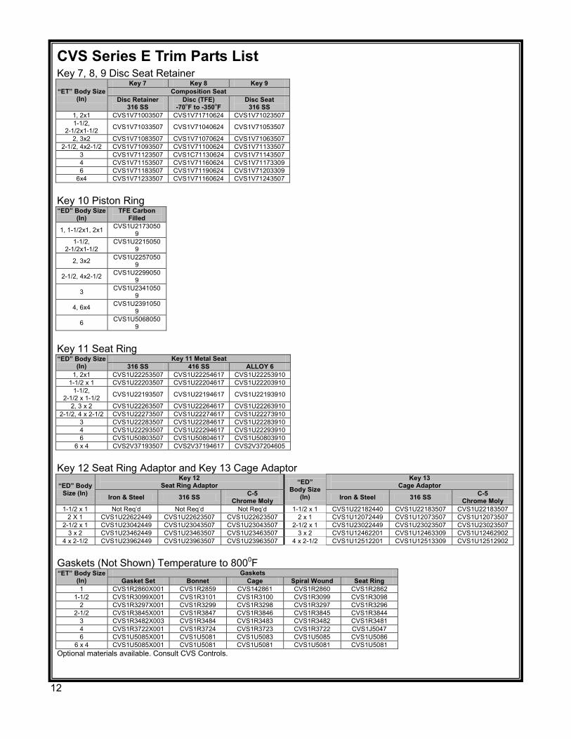
CVS Series E Trim Parts List Key 7, 8, 9 Disc Seat Retainer “ET” Body Size
(In)
Key 7 Key 8 Key 9 Composition Seat
Disc Retainer 316 SS
Disc (TFE) -70oF to -350oF
Disc Seat 316 SS
1, 2x1 CVS1V71003507 CVS1V71710624 CVS1V71023507 1-1/2,
2-1/2x1-1/2 CVS1V71033507 CVS1V71040624 CVS1V71053507
2, 3x2 CVS1V71083507 CVS1V71070624 CVS1V71063507 2-1/2, 4x2-1/2 CVS1V71093507 CVS1V71100624 CVS1V71133507
3 CVS1V71123507 CVS1C71130624 CVS1V71143507 4 CVS1V71153507 CVS1V71160624 CVS1V71173309 6 CVS1V71183507 CVS1V71190624 CVS1V71203309
6x4 CVS1V71233507 CVS1V71160624 CVS1V71243507
Key 10 Piston Ring “ED” Body Size
(In) TFE Carbon
Filled
1, 1-1/2x1, 2x1 CVS1U21730509
1-1/2, 2-1/2x1-1/2
CVS1U22150509
2, 3x2 CVS1U22570509
2-1/2, 4x2-1/2 CVS1U22990509
3 CVS1U23410509
4, 6x4 CVS1U23910509
6 CVS1U50680509
Key 11 Seat Ring “ED” Body Size
(In) Key 11 Metal Seat
316 SS 416 SS ALLOY 6 1, 2x1 CVS1U22253507 CVS1U22254617 CVS1U22253910
1-1/2 x 1 CVS1U22203507 CVS1U22204617 CVS1U22203910 1-1/2,
2-1/2 x 1-1/2 CVS1U22193507 CVS1U22194617 CVS1U22193910
2, 3 x 2 CVS1U22263507 CVS1U22264617 CVS1U22263910 2-1/2, 4 x 2-1/2 CVS1U22273507 CVS1U22274617 CVS1U22273910
3 CVS1U22283507 CVS1U22284617 CVS1U22283910 4 CVS1U22293507 CVS1U22294617 CVS1U22293910 6 CVS1U50803507 CVS1U50804617 CVS1U50803910
6 x 4 CVS2V37193507 CVS2V37194617 CVS2V37204605
Key 12 Seat Ring Adaptor and Key 13 Cage Adaptor “ED” Body
Size (In)
Key 12 Seat Ring Adaptor “ED”
Body Size (In)
Key 13 Cage Adaptor
Iron & Steel 316 SS C-5 Chrome Moly Iron & Steel 316 SS C-5
Chrome Moly 1-1/2 x 1 Not Req’d Not Req’d Not Req’d 1-1/2 x 1 CVS1U22182440 CVS1U22183507 CVS1U22183507
2 X 1 CVS1U22622449 CVS1U22623507 CVS1U22623507 2 x 1 CVS1U12072449 CVS1U12073507 CVS1U12073507 2-1/2 x 1 CVS1U23042449 CVS1U23043507 CVS1U23043507 2-1/2 x 1 CVS1U23022449 CVS1U23023507 CVS1U23023507
3 x 2 CVS1U23462449 CVS1U23463507 CVS1U23463507 3 x 2 CVS1U12462201 CVS1U12463309 CVS1U12462902 4 x 2-1/2 CVS1U23962449 CVS1U23963507 CVS1U23963507 4 x 2-1/2 CVS1U12512201 CVS1U12513309 CVS1U12512902
Gaskets (Not Shown) Temperature to 8000F “ET” Body Size
(In) Gaskets
Gasket Set Bonnet Cage Spiral Wound Seat Ring 1 CVS1R2860X001 CVS1R2859 CVS142861 CVS1R2860 CVS1R2862
1-1/2 CVS1R3099X001 CVS1R3101 CVS1R3100 CVS1R3099 CVS1R3098 2 CVS1R3297X001 CVS1R3299 CVS1R3298 CVS1R3297 CVS1R3296
2-1/2 CVS1R3845X001 CVS1R3847 CVS1R3846 CVS1R3845 CVS1R3844 3 CVS1R3482X003 CVS1R3484 CVS1R3483 CVS1R3482 CVS1R3481 4 CVS1R3722X001 CVS1R3724 CVS1R3723 CVS1R3722 CVS1J5047 6 CVS1U5085X001 CVS1U5081 CVS1U5083 CVS1U5085 CVS1U5086
6 x 4 CVS1U5085X001 CVS1U5081 CVS1U5081 CVS1U5081 CVS1U5081 Optional materials available. Consult CVS Controls.
12
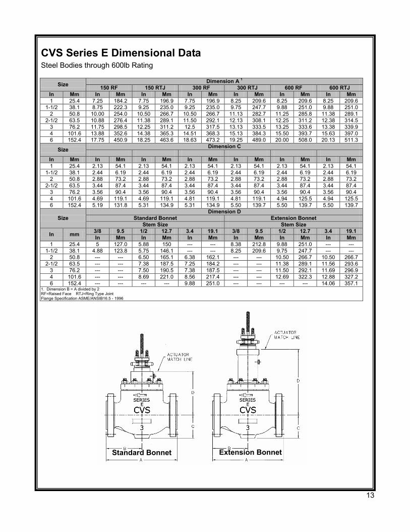
CVS Series E Dimensional Data Steel Bodies through 600lb Rating
Size Dimension A 1 150 RF 150 RTJ 300 RF 300 RTJ 600 RF 600 RTJ
In Mm In Mm In Mm In Mm In Mm In Mm In Mm 1 25.4 7.25 184.2 7.75 196.9 7.75 196.9 8.25 209.6 8.25 209.6 8.25 209.6
1-1/2 38.1 8.75 222.3 9.25 235.0 9.25 235.0 9.75 247.7 9.88 251.0 9.88 251.0 2 50.8 10.00 254.0 10.50 266.7 10.50 266.7 11.13 282.7 11.25 285.8 11.38 289.1
2-1/2 63.5 10.88 276.4 11.38 289.1 11.50 292.1 12.13 308.1 12.25 311.2 12.38 314.5 3 76.2 11.75 298.5 12.25 311.2 12.5 317.5 13.13 333.5 13.25 333.6 13.38 339.9 4 101.6 13.88 352.6 14.38 365.3 14.51 368.3 15.13 384.3 15.50 393.7 15.63 397.0 6 152.4 17.75 450.9 18.25 463.6 18.63 473.2 19.25 489.0 20.00 508.0 20.13 511.3
Size Dimension C
In Mm In Mm In Mm In Mm In Mm In Mm In Mm 1 25.4 2.13 54.1 2.13 54.1 2.13 54.1 2.13 54.1 2.13 54.1 2.13 54.1
1-1/2 38.1 2.44 6.19 2.44 6.19 2.44 6.19 2.44 6.19 2.44 6.19 2.44 6.19 2 50.8 2.88 73.2 2.88 73.2 2.88 73.2 2.88 73.2 2.88 73.2 2.88 73.2
2-1/2 63.5 3.44 87.4 3.44 87.4 3.44 87.4 3.44 87.4 3.44 87.4 3.44 87.4 3 76.2 3.56 90.4 3.56 90.4 3.56 90.4 3.56 90.4 3.56 90.4 3.56 90.4 4 101.6 4.69 119.1 4.69 119.1 4.81 119.1 4.81 119.1 4.94 125.5 4.94 125.5 6 152.4 5.19 131.8 5.31 134.9 5.31 134.9 5.50 139.7 5.50 139.7 5.50 139.7
Size Dimension D
Standard Bonnet Extension Bonnet Stem Size Stem Size
In mm 3/8 9.5 1/2 12.7 3.4 19.1 3/8 9.5 1/2 12.7 3.4 19.1 In Mm In Mm In Mm In Mm In Mm In Mm
1 25.4 5 127.0 5.88 150 --- --- 8.38 212.8 9.88 251.0 --- --- 1-1/2 38.1 4.88 123.8 5.75 146.1 --- --- 8.25 209.6 9.75 247.7 --- ---
2 50.8 --- --- 6.50 165.1 6.38 162.1 --- --- 10.50 266.7 10.50 266.7 2-1/2 63.5 --- --- 7.38 187.5 7.25 184.2 --- --- 11.38 289.1 11.56 293.6
3 76.2 --- --- 7.50 190.5 7.38 187.5 --- --- 11.50 292.1 11.69 296.9 4 101.6 --- --- 8.69 221.0 8.56 217.4 --- --- 12.69 322.3 12.88 327.2 6 152.4 --- --- --- --- 9.88 251.0 --- --- --- --- 14.06 357.1
1. Dimension B = A divided by 2RF=Raised Face RTJ=Ring Type Joint Flange Specification ASME/ANSIB16.5 - 1996
Standard Bonnet Extension Bonnet
13

Notes
14
Notes
CVS Controls Ltd. strives for the highest levels of quality and accuracy. The information included in this publication is presented for informational purposes only. CVS Controls Ltd. reserves the right to modify or change, and improve design, process, and specifications without written notice. Under no circumstance is the information contained to be interpreted to be a guarantee/warranty with regard to our products or services, applicability or use. Selection, use and maintenance are the sole responsibility of the end user and purchaser. CVS Controls assumes no liability for the selection use and maintenance of any product.
15
Head Office 3900 – 101 Street Edmonton, Alberta, Canada T6E 0A5 Office: (780) 437-3055 Fax: (780) 436-5461
Website: www.cvs-controls.com E-Mail: [email protected]
Calgary Sales Office 3516 114 Avenue SE
Calgary, Alberta, Canada T2Z3V6 Office: (403) 250-1416
Fax: (403) 291-9487
Rev 7 Oct 2013 Printed in Canada
16