Embed Size (px)
Citation preview

Instruction Manual


Instruction Manual � Oceanus
i
INTRODUCTION
This manual contains operating instructions and mainten-ance schedules for the high pressure breathing air com-pressor unit
WARNING
! Pneumatic high pressure system !
The breathing air produced with the compressor units de-scribed in this manual is subject to strict quality standards.Ignoring the operating and maintenance instructions canlead to severe injury or death.
This compressor has been built in accordance with the ECmachine regulations 98/37/EG. Specifications on the noiselevel in accordance with the machine and product safetylaw as of May 2004 and the EC machine regulations, chapt.I, section 1.7.4. The machine has been built according tothe highest standard of technology and the generally ac-knowledged safety standards. Nevertheless, operationcould still cause danger for the operating personnel or thirdparties, or result in damage to the machine and other val-ues. The machine may only be used to produce com-pressed air as specified in this manual. Other use is strictlyprohibited.
All instructions should be observed and carried out in theorder laid down to prevent damage and premature wear tothe equipment.
The manufacturer and the supplier void all responsibility fordamage or injury resulting from failure to follow theseinstructions.
Edition January 2009© 2009 BAUER Kompressoren GmbH, Munich
All rights reserved.
Oceanus

A
B C
�30
Instruction Manual � Oceanus
ii
Dear customer
We are happy to give you advice on any questions regard-ing your BAUER compressor and help as soon as poss-ible with any arising problems.
You can contact us Mondays to Thursdays from 0800 till1630, Fridays from 0800 till 1400 on phone no. (089)78049−0.If you call the following extensions directly, it will save youtime and continuous dialling.
Do you want to order spare parts?
� Customer servicePhone no: (089) 78049−129 or −149Fax no: (089) 78049−101
Do you have problems with maintenance or repair work?
� Technical customer servicePhone no: (089) 78049−176 or −246Fax no: (089) 78049−101
Do you need further information regarding your unit, ac-cessories, prices etc.?
� Sales departmentPhone no: (089) 78049−138, −185, −154, −205 or −202Fax no: (089) 78049−103
Are you interested in any training courses?
� Training managerPhone no: (089) 78049−175Fax no: (089) 78049−103
Or visit us in the inernet at: www.bauer−kompressoren.de
Explanation of the short operating instructions on the unit
Read instruction manual beforeoperating unit
� chapter 3.
Check oil level on compressor andpetrol engine before operating unit
� chapter 4.4.1.
Drain condensate at least every 15minutes (3 locations)
� chapter 4.4.3. and 4.4.4.
Position units with petrol enginewith exhaust in wind direction toprevent exhaust fumes beingsucked in by the compressor
� chapter 3.
Petrol driven units must not be op-erated indoors.
� chapter 3.
Position unit level: max. inclinationElectric unit: 30°Petrol unit: 20°
� chapter 3.
Operate unit only at ambient tem-peratures between +5 and +45 °C
� chapter 3.
Keep away from hot surfaces onmotor and compressor
� chapter 2.
Wear ear protectors when unit isrunning
� chapter 2.

Instruction Manual � Oceanus
iii
CONTENTS
1. GENERAL 1. . . . . . . . . . . . . . . . . . . . . . . . . . . . . . . . . . . . . . . . . . . . . . . . . . . . . . . . . . . . . . . . . . . . . . . . . . . . . . . 2. SAFETY MEASURES 5. . . . . . . . . . . . . . . . . . . . . . . . . . . . . . . . . . . . . . . . . . . . . . . . . . . . . . . . . . . . . . . . . . . . . 3. LOCATION, OPERATION, BOTTLE FILLING 9. . . . . . . . . . . . . . . . . . . . . . . . . . . . . . . . . . . . . . . . . . . . . . . . . 4. MAINTENANCE 17. . . . . . . . . . . . . . . . . . . . . . . . . . . . . . . . . . . . . . . . . . . . . . . . . . . . . . . . . . . . . . . . . . . . . . . . . . 5. STORAGE, PRESERVATION 32. . . . . . . . . . . . . . . . . . . . . . . . . . . . . . . . . . . . . . . . . . . . . . . . . . . . . . . . . . . . . . 6. REPAIR INSTRUCTIONS 33. . . . . . . . . . . . . . . . . . . . . . . . . . . . . . . . . . . . . . . . . . . . . . . . . . . . . . . . . . . . . . . . . . 7. TABLES 34. . . . . . . . . . . . . . . . . . . . . . . . . . . . . . . . . . . . . . . . . . . . . . . . . . . . . . . . . . . . . . . . . . . . . . . . . . . . . . . . . 8. ANNEX 35. . . . . . . . . . . . . . . . . . . . . . . . . . . . . . . . . . . . . . . . . . . . . . . . . . . . . . . . . . . . . . . . . . . . . . . . . . . . . . . . . .
INDEX
AAdhesive chart, 34Air flow diagram, 1Annex, 35
BB−Timer, 13
CChange of oil type, 18Change−over device, 12Cooling system, 29
DDesign, 1Drive system, 27
EV−belt, tension meter, 27Electrical system, 28
FFilling procedure, 10Filter system, 19
IIntake filter, 18Intermediate separator, 19Intake air quality, 10
LLocation, 9Lubrication, 17Lubrication chart, 34
MMaintenance, 17
Maintenance instructions, 17Maintenance record, 17Maintenance schedule, 17Motor protection switch, 28
OOil change, 17, 18Oil level check, 17Oil type, 17Operation, 9
PPreservation, 32Pressure gauge, 25Pressure−maintaining valve, 24
RRepair instructions, 33
SSafety valves, 24Sealant chart, 34Shut−down, 12Storage, 32
TTables, 34Technical data, 4Telescopic intake tube, 18Testing agents, 34Tightening torque values, 34Torque sequence, 34Trouble−shooting, 30
VValves, 25
ANNEX
Schematic diagram motor protection switch, three phase current KB 76942−992−S1Lubricating oil list KB 70851−994Applicable parts list TO−1/8

Instruction Manual � Oceanus
iv
NOTES
Model:Serial No..:Date of purchase:Dealer address / phone no.:

11
12
13
14
1
3
8
4
10
65
7
2
9
Instruction Manual � Oceanus
1
1. GENERAL
PURPOSE
The Oceanus breathing air compressor is designed tocompress air for breathing as required in diving applica-tions. The max. allowable operating pressure (adjustedpressure on final pressure safety valve) is 225 bar (3,200psi) or 330 bar (4,700 psi).
DESIGN
The compressor unit comprises the following major as-semblies:− compressor block− drive motor− filter system P21− filling assembly− base plate and frameThe design of the compressor system is shown in Fig. 1to Fig. 4.
AIR FLOW DIAGRAM
See Fig. 5 . The air is drawn in through telescopic tube(necessary for units with petrol engine) −1, intake filter −2;compressed to final pressure in cylinders −3, −4, −5; re-cooled by intercoolers −6, −7, and aftercooler −9. Thepressures of the single stages are protected by safetyvalves −10, −11, −12. The compressed air is pre−cleanedin intermediate separator −8 and purified in filter systemP21 −13. Intermediate separator and filter system P21 aredrained by means of condensate drain valves −15. Pres-sure maintaining valve −16 provides a constant pressurewithin the filter assembly. The compressed, purified air ispassed through filling hose −17 and filling valve −18 to thebottles to be filled. Filling pressure is indicated at pressuregauge −19. With change over device it is possible to fillbottles with 200 bar nominal pressure by opening valve−21 at filling valve −18. Safety valve −20 is adjusted to ablow off pressure of 225 bar.
Fig. 1 Compressor unit with petrol engine
1 Filling hose2 Exhaust3 Air filter4 Tank5 Throttle lever6 Choke lever7 Fuel cock
8 Starter rope9 Engine stop switch (ignition)10 Filling valve with final pressure gauge11 Safety valve, final pressure12 Filter system P2113 B−Timer14 Condensate drain taps

Instruction Manual � Oceanus
2
1 Filling hose2 Filling valve with pressure gauge3 Motor terminal box4 Three−phase motor5 Final pressure safety valve6 Handle7 Fanwheel cover8 B−Timer9 Condensate drain valves10 Mains plug with ON−OFF switch and motor
protection circuit breaker (dep. on country)
6
1
2
4
3
5
7
8
9
10
Fig. 2 Compressor unit with electric motor (three−phase current)
1 Filling hose2 Filling valve with pressure gauge3 Motor terminal box with ON−OFF switch4 Single−phase motor5 Final pressure safety valve6 Handle7 Fanwheel cover8 Pressure maintaining valve9 Condensate drain valves
6
1
2
4
3
5
7
8
9
Fig. 3 Compressor unit with electric motor (alternating current)

Instruction Manual � Oceanus
3
1 Intake filter2 Inter−cooler 1st stage3 Safety valve 1st stage4 Cylinder 2nd stage5 Inter−cooler 2nd stage6 Oil dipstick7 Safety valve 2nd stage8 Intermediate separator 2nd stage9 Cooling air fan10 After−cooler11 Compressed air outlet12 Condensate drain tap
1
2
4
3
6
7
5
9
8
10
11
12
Fig. 4 Compressor block Oceanus
1 Telescopic air intake2 Intake filter3 Cylinder 1st stage4 Cylinder 2nd stage5 Cylinder 3rd stage6 Inter−cooler 1st/2nd stage7 Inter−cooler 2nd/3rd stage
8 Intermed. separator 2nd/3rd stage9 After−cooler10 Safety valve 1st stage11 Safety valve 2nd stage12 Final pressure safety valve13 Filter system P2114 TRIPLEX longlife cartridge
15 Condensate drain valve16 Pressure maintaining valve17 Filling hose18 Filling valve19 Final pressure gauge20 Safety valve, final pressure PN 20021 Change over device (optional extra)
8
11
15
2
1
3
4 5
6
7
9
10
12
13
14
1516
17
17
18
18
19
19
20
21
Fig. 5 Air flow diagram
Instruction Manual � Oceanus
4
TECHNICAL DATA
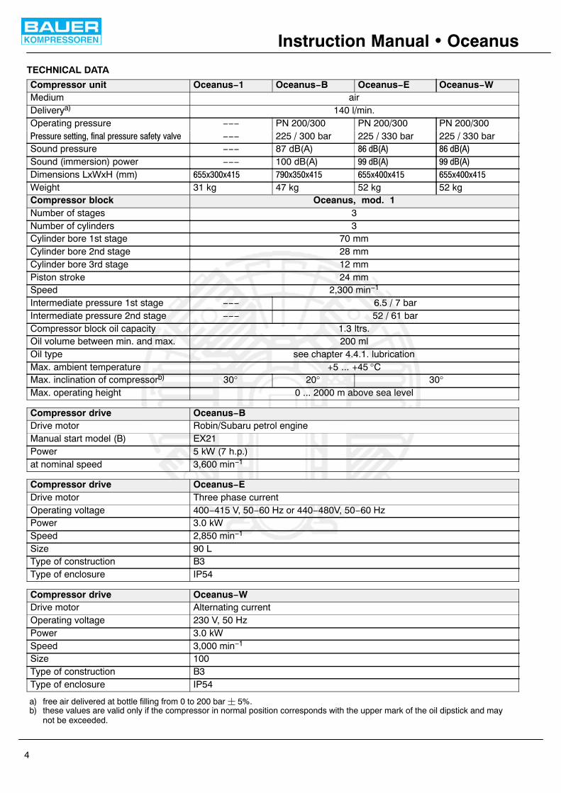
Compressor unit Oceanus−1 Oceanus−B Oceanus−E Oceanus−WMedium airDeliverya) 140 l/min.Operating pressure −−− PN 200/300 PN 200/300 PN 200/300Pressure setting, final pressure safety valve −−− 225 / 300 bar 225 / 330 bar 225 / 330 barSound pressure −−− 87 dB(A) 86 dB(A) 86 dB(A)Sound (immersion) power −−− 100 dB(A) 99 dB(A) 99 dB(A)Dimensions LxWxH (mm) 655x300x415 790x350x415 655x400x415 655x400x415Weight 31 kg 47 kg 52 kg 52 kgCompressor block Oceanus, mod. 1Number of stages 3Number of cylinders 3Cylinder bore 1st stage 70 mmCylinder bore 2nd stage 28 mmCylinder bore 3rd stage 12 mmPiston stroke 24 mmSpeed 2,300 min−1
Intermediate pressure 1st stage −−− 6.5 / 7 barIntermediate pressure 2nd stage −−− 52 / 61 barCompressor block oil capacity 1.3 ltrs.Oil volume between min. and max. 200 mlOil type see chapter 4.4.1. lubricationMax. ambient temperature +5 ... +45 °CMax. inclination of compressorb) 30° 20° 30°Max. operating height 0 ... 2000 m above sea level
Compressor drive Oceanus−BDrive motor Robin/Subaru petrol engineManual start model (B) EX21Power 5 kW (7 h.p.)at nominal speed 3,600 min−1
Compressor drive Oceanus−EDrive motor Three phase currentOperating voltage 400−415 V, 50−60 Hz or 440−480V, 50−60 HzPower 3.0 kWSpeed 2,850 min−1
Size 90 LType of construction B3Type of enclosure IP54
Compressor drive Oceanus−WDrive motor Alternating currentOperating voltage 230 V, 50 HzPower 3.0 kWSpeed 3,000 min−1
Size 100Type of construction B3Type of enclosure IP54
a) free air delivered at bottle filling from 0 to 200 bar � 5%.b) these values are valid only if the compressor in normal position corresponds with the upper mark of the oil dipstick and may
not be exceeded.

MV
3−A
/10/
06
WARNING
Instruction Manual � Oceanus
5
2. SAFETY MEASURES
2.1. NOTES AND WARNING SIGNS
Notes and warning signs displayed on compressors ac-cording to model, application or equipment.
WARNING
Hot surfaces, do not touch!
Danger of burning by touching cylinders,cylinder heads and pressure lines of indi-vidual compressor stages.
WARNING
High voltage!
Life threatening danger of electric shock.Maintenance work on electric units or op-erating equipment may only be carriedout by a qualified electrician or by a per-son instructed and supervised by a quali-fied electrician according to electrical reg-ulations.
WARNING
Automatic compressor control, unit maystart−up without warning!
Before carrying out maintenance and re-pair work, switch off at the main switch ordisconnect from the mains and ensureunit will not restart.
MANDATORY
Instructions must be read by persons op-erating the machinery!
The instruction manual supplied and allother applicable instructions, regulationsetc. must be read and understood by op-erating personnel before using the ma-chine.
MANDATORY
Hearing protectors must be worn!
Hearing protectors must be worn whenworking on a machine which is running.
NOTE
Ensure correct direction of rotation!
When switching on the machine, checkthe arrow to ensure correct direction ofrotation of the drive motor.
2.2. IDENTIFYING THE SAFETY NOTICES
Important instructions concerning the endangerment ofpersonnel, technical safety and operating safety will bespecially emphasized by placing the following signs be-fore the instructions.
This notice is used with maintenancework and operating procedures andmust be adhered to exactly in order to
avoid endangering personnel.
This notice must be complied with in order toavoid damage to or destruction of the ma-chine or its equipment.
This notice advises of technical require-ments which the operator must take particu-lar note of.
2.3. FUNDAMENTAL SAFETY NOTICES
2.3.1. Authorized use• The machine / unit is built according to state of the art
technology and established safety technical regula-tions. Nevertheless, its use can cause danger to lifeand limb of the operator or third parties or damage tothe machine and other equipment.
• Operate the machine / unit only in technically perfectcondition in accordance with regulations and safetyand danger notices detailed in the instruction manual!In particular, immediately correct faults (or have themcorrected) which can impair safety!
• The machine / unit is exclusively for the compressionof mediums (air/gas) specified in section A, chapter1.3. “Technical data”. Any other medium or use outsidethat specified is not authorized. The manufacturer /supplier is not liable for damage resulting from this.The user alone is responsible for this risk. Authoriz-ation for use is also under the condition that the instruc-tion manual is complied with and inspection and main-tenance requirements are enforced.
2.3.2. Organizational measures• Keep the instruction manual to hand near the machine
/ unit at all times in the relevant holder.• In addition to the instruction manual, observe and com-
ply with universally valid legal and other obligatory re-gulations regarding accident prevention and environ-ment protection. See chapter 2.4. This can involve, forexample, contact with hazardous substances or theprovision / wearing of personal protective equipment.
• Personnel engaged to operate the machine must haveread the instruction manual before beginning work, es-pecially the safety notices chapter. When work is al-ready underway it is too late. This is particularly rel-evant for temporary personnel, e.g. maintenance per-sonnel.

Instruction Manual � Oceanus
6
• Personnel may not wear long hair loose, loose clothingor jewellery, including rings. There is a danger of injurythrough, for example, these getting caught or beingpulled into the equipment.
• As far as necessary or according to regulations, usepersonal protective equipment.
• Observe all safety and danger notices on the unit.• Keep all safety and danger notices on the machine /
unit complete and in readable condition.• If there are any modifications to the unit or operating
conditions which may affect safety, stop the unit im-mediately and inform the person responsible of thefault.
• No modifications may be made to the unit which couldimpair safety without first obtaining permission fromthe suppliers. This is also the case with regard to in-stallation and adjustment of safety devices and valvesas well as welding of piping and reservoirs.
• Spare parts must always comply with the technical re-quirements specified by the manufacturer. This is al-ways guaranteed with original spare parts.
• Piping must be thoroughly checked (pressure and vis-ual inspection) by the operator at appropriate time in-tervals, even if no safety related faults have been no-ticed.
• Intervals stipulated or given in the instruction manualfor recurring checks / inspections must be adhered to.
• Make sure location and operation of fire extinguishersis known.
• Pay attention to fire warning and fire fighting pro-cedures.
2.3.3. Qualifications, fundamental duties• Work on / with the unit may only be carried out by reli-
able personnel. Observe the legal minimum age per-missible.
• Ensure that only trained personnel work with the ma-chine.
• Establish the responsibilities of the machine operatorand establish a procedure for him to inform a third per-son of unfavourable safety conditions.
• People who are being trained or introduced to the jobshould only be allowed to work with the unit under con-stant supervision of an experienced person.
• Work on the electrical equipment of the unit may onlybe carried out by a qualified electrician or by an in-structed person under the direction and supervision ofa qualified electrician according to electrotechnical re-gulations.
2.3.4. Safety notices for operation• Do not carry out any work if safety is questionable.• Meet all requirements demanding that the unit is only
operated in safe and good working order. Only operatethe machine if all protective and safety equipment, e.g.all detachable protective equipment, emergency shut−down devices, soundproofing is provided and in goodworking order.
• At least once every day, check the unit externally fordamage and faults. Inform the person responsible im-mediately if anything is not as is should be (including
operation). If necessary, shut the machine down im-mediately and make it safe.
• Observe switching on and off processes and monito-ring indications according to the instruction manual.
• Before switching on / starting up the unit, ensure thatno one can be put at risk through running the unit.
• Carry out the setting, maintenance and inspection pro-cesses at the intervals specified in the instruction man-ual, including replacement of parts / equipment. Thiswork may only be carried out by qualified personnel.
• Clear and make the maintenance area safe as far asnecessary.
• If the unit is completely switched off for maintenanceand repairwork, ensure that it is protected from unex-pected start−up. Turn off main control device and re-move the key and / or display a warning sign on themain switch.
• When replacing individual parts and larger assemblygroups, they must be carefully fastened to the liftingdevice so that there is no risk of danger. Use only suit-able and technically perfect lifting devices and equip-ment with sufficient lifting power and strength. Do notlinger or work under suspended loads.
• Only entrust an experienced person with the fixing ofloads and guiding of crane drivers. The person guidingmust remain within sight or in contact with the operator.
• For assembly work above body height, use appropri-ate safety approved equipment, e.g. ladders and plat-forms. Do not climb on machine parts. For mainten-ance work at high levels, wear a safety harness.
• Clean oil, fuel or care products from the machine, inparticular the connections and screw joints, beforecarrying out maintenance / repairwork. Do not use ag-gressive cleaning fluid. Use a fibre−free cleaning cloth.
• Before cleaning the machine with water or jet of steam(high pressure cleaner) or detergent, cover / seal allopenings which for safety and/or operating reasons nowater / steam / detergent may penetrate. Electricmotor and switch cabinets are particularly at risk.
• When cleaning the operating room, ensure that thetemperature sensors of the fire alarm and sprinklersystem do not come into contact with hot cleaning fluid,in order to avoid triggering the sprinkler system.
• Completely remove all covers / seals after cleaning.• After cleaning, check all pressure lines for leaks, loose
connections, wear and damage. Immediately elimin-ate any faults.
• Always retighten any screw connections loosened formaintenance or repairwork.
• If it is necessary to remove safety devices for mainten-ance and repairwork, these must be replaced andchecked immediately after completion of the mainten-ance or repairwork.
• Ensure safe and environmentally friendly disposal ofconsumables and old parts.
2.3.5. Particular areas of danger
• Use only original fuses with specified current rating. Ifthere is a failure in the electric energy supply, shut theunit down immediately.

Instruction Manual � Oceanus
7
• Work on electric units or operating equipment may onlybe carried out by a qualified electrician or by a personunder the instruction and supervision of a qualifiedelectrician according to electric technical regulations.
• Machines and unit parts which must undergo inspec-tion, maintenance and repairwork, must be discon-nected from the mains supply, if specified. Parts whichhave been disconnected must first be checked for volt-age, then earthed and short−circuited and isolatedfrom live neighbouring parts.
• The electrical equipment of a unit must be regularlychecked. Defects, such as loose screw connections orburnt wires, must be rectified immediately.
• If work is to be carried out on live parts, work with a sec-ond person who can operate the emergency off switchor the main switch in the case of an emergency. Closeoff the work area with a red and white safety chain anda warning sign. Only use voltage isolated tools.
• Only personnel with particular knowledge and experi-ence with pneumatics may carry out work on pneu-matic equipment.
• Check all pressure lines, hoses and screw connectionsregularly for leaks and visible damage. Immediately re-pair any damage. Escaping air under pressure cancause injury and fire.
• Depressurize system and pressure lines before com-mencing repairwork.
• Pressurized air lines must be laid and mounted byqualified personnel. Connections must not be mixedup. Fittings, length and quality of the piping must corre-spond to requirements.
• Soundproofing equipment on the unit must be in placeand functional during operation.
• The stipulated hearing protectors must be worn.• With regard to oil, grease and other chemical sub-
stances, observe the relevant safety regulations forthe product.
• For loading, only use lifting device and equipment withsufficient lifting power and strength.
• Use only suitable transporters with sufficient carryingpower. Secure the load properly. Use suitable fixingpoints.
• If necessary, provide unit with transportation brackets.Display the appropriate notice. Remove transportationbrackets in the correct manner before taking into oper-ation.
• Parts which need to be dismantled for transport pur-poses must be carefully replaced and secured beforetaking into operation.
• Even when moving the unit only slightly, the unit mustbe disconnected from all external energy sources. Be-fore putting into use again, reconnect the machine tothe mains according to regulations.
• When taking back into operation, proceed according tothe instruction manual.
2.3.6. Notices of danger regarding pressure vessels• Never open or loosen pressure vessel lids or pipe con-
nection parts under pressure; always depressurise thevessel or the unit.
• Never exceed the permissible operating pressure ofthe vessels!
• Never heat the vessels or any of their parts above thestated, maximum operating pressure.
• Always exchange damaged pressure vessels com-pletely. Individual parts that are subject to pressureloads cannot be purchased as spare parts, since thevessels are tested as a complete part and the docu-mentation considers them as a whole (see pressurevessel documentation, serial−numbers!).
• Always pay attention to the permissible operatingmode of the pressure vessels. We differentiate:− vessels for static load− vessels for dynamic loadVessels for static load:These pressure vessels are permanently under vir-tually constant operating pressure; the fluctuations ofpressure are very small.Vessels for this type of load are not marked in a particu-lar way and may be used as long as the vessel inspec-tions, carried out regularly, do not uncover any safety−relevant deficiencies.We recommend that aluminium vessels should beexchanged after 15 years at the latest.Vessels for dynamic load:These pressure vessels may also be used underconditions of changing operating pressure. The pres-sure may vary between the atmospheric and the maxi-mum admissible operating pressure.The pressure vessel documentation and the appropri-ate notes in the operating manual particularly char-acterise vessels of this type as being adequate for dy-namic loads. In the technical information for thesevessels you will find specifications concerning theirpermissible operating period.Due to the variation of the operating pressure, thesevessels are subject to a so−called dynamic load, whichputs the vessels under great stress. The change be-tween two different pressures is called a load changeor cycle. In the technical information for these vesselsyou will find specifications concerning the permissiblenumber of cycles depending on the fluctuation of theoperating pressure.Having reached half the permissible number of cycles,the vessel has to be submitted to an internal check, inwhich the critically stressed areas of the vessels areexamined by means of suitable testing methods, inorder to ensure the operating safety.After having reached the total permissible number ofload cycles, the vessel must be exchanged andscrapped.Record the number of load cycles in writing if you donot have an automatic cycle−counter.
Instruction Manual � Oceanus
8
We recommend that aluminium vessels should beexchanged after 15 years at the latest.Please pay attention to and follow these measures, foryour own safety and that of you employees and cus-tomers!In order not to unnecessarily load the pressure vesselsadditionally, the non−return valves, that are meant toavoid a drop in pressure, and also the pressure main-taining valves, which should reduce big pressurefluctuations as well, should be checked regularly for in-ternal and external tightness and functionality.
• Check the pressure vessels regularly on the inside andoutside for damage from corrosion.
• Be particularly careful with second−hand pressurevessels, when their previous operating mode is notspecifically clarified.
2.4. SAFETY REGULATIONS (EC; partly Germany,only)A compressor is identified by German law as being a fillingsystem if pressure cylinders are filled by the system, es-pecially when these cylinders are made available for thirdparties. The start−up and operation of compressor sys-tems for use as filling stations is governed by the followingregulations:Pressure vessel directive (Directive 97/23/EC) of29.05.1997Operating safety regulations (BetrSichV) of27.09.2002Machine safety law (GSG) of 11.05.200114th regulation to machine safety law (14. GSGV −pressure vessel regulation) of 03.10.2002Technical regulations for pressure gases (TRG 400,401, 402, 730).If a high pressure compressor is used for filling pressurevessels or for the supply of pneumatic systems, the follow-ing regulations apply:Accident Prevention Regulations (UVV):BGV A1 of 01. January 2004
Copies of the above regulations are available through theusual outlets, e.g. in Germany from:
Carl Heymanns VerlagLuxemburger Str. 44950939 Köln
Beuth−Vertrieb GmbHBurggrafenstr. 4 − 710787 Berlin
The manufacturer has complied with all applicable regula-tions and the unit is prepared accordingly. If desired, weoffer at our Munich site a partial acceptance test accord-ing to § 14 BetrSichV. Please contact our Technical Ser-vice Department with regard to this. They can also supplyour leaflet “IMPORTANT NOTES FOR CERTIFI-CATION”.
According to the operation safety regulations (BetrSichV),all compressor units which will be used as filling stationsmust undergo an acceptance test by a professional attheir location before bringing them into service. If pressurevessels (bottles) are to be filled by the compressor for athird party then the appropriate permission must be ob-tained from the responsible authority before the accept-ance test. As a rule, this is the factory inspectorate. Theprocedure for obtaining permission is according to TRG730, guidelines for permission to set up and operate fillingstations. The test certificates and documents deliveredwith the compressor are important and may be requestedduring the procedure for obtaining permission. In addition,the documents belonging to the unit are important for re-current inspections and should therefore be carefully kept.
Inspections in accordance with the regulations for preven-tion of accidents will be carried out by the manufacturer orby a specialist.
No guarantees whatsoever are valid for damage causedor favoured by the non−consideration of these directionsfor use.
We strongly emphasize these regulations.

WARNING
Instruction Manual � Oceanus
9
3. LOCATION, OPERATION, BOTTLE FILLING
LOCATION
Outdoor location
The compressor unit is not seawater re-sistant. At operation in salty air spraycompressor with anticorrosive protec-tion (e. g. Quicksilver Corrosion Guard).
Electric driven units should be operated and storedbelow deck. Units with petrol engine should also bestored below deck after the filling process.
Keep unit away from inflammable items.Do not smoke while petrol tank is openand while unit is in operation.
− Locate the unit level.
− On units with petrol engine it is most important that onlyclean air be used, position compressor in direction ofwind so that exhaust fumes are blown away from theunit.
− Turn unit as soon as wind direction changes.
− Take care that no vehicles are in direct vicinity with en-gines running.
− Do not operate unit in the vicinity of open fire (fluegas!).
Indoor location
Petrol driven units must not be operatedindoors.
− Ensure adequate ventilation.
− Here too, air must be free from exhaust fumes and haz-ardous vapours (e.g. smoke, solvent vapours, etc.).
− If possible install unit in such a manner that the com-pressor fan can get fresh air from outside, for instancethrough an opening in the wall.
− Ensure that an adequate exhaust air opening is pro-vided.
− When locating the compressor in small rooms wherenatural ventilation is not ensured, measures must betaken to provide artificial ventilation (this also applieswhen other systems having high radiation are operat-ing in the same room).
Electrical installation
For installation of electrical equipment observe the follow-ing:
− Comply with regulations of local electricity supply com-pany.
− Arrange for the electrics to be connected by an electri-cian only.
− Ensure correct installation of protective conductor.
− Check conformity of motor tension and frequency withthose of electric network.
− Operate electric units only on mains sockets equippedwith fault current circuit breaker according to DIN VDE0664 with a nominal differential current of less than 30mA (up to 16 A in single−phase AC circuits).
− For units not connected through a plug, but perma-nently installed, a main switch must be provided whichhas a contact gap of minimum 3 mm on each pole.
− Fuse motor correctly; use slow−blow fuses, only.
− Immediately after start−up check direction of rotationfor agreement with arrow on unit.
If power supply cable is to be replaced,use cable of same type, only!
− When using extension leads or cable drums, operateunit with unwound cable, only to avoid overheating andrisk of fire. The maximum length for extension cablesat normal ambient temperatures (approx. 20 °C) is 25metres.
OPERATION
Preparation for operation
All compressor units are tested prior todelivery to the customer, so after correctinstallation of the unit there should be no
problem putting it into operation, observing the fol-lowing points:
The compressors described in thismanual are not suitable for com-pression of oxygen. EXPLOSION
occurs if an oil lubricated compressor is operatedwith pure oxygen or gases with an oxygen content ofmore than 21%!
− Prior to first operation read Instruction Manual care-fully. Make sure that all persons handling the com-pressor and the filling station are familiar with the func-tion of all controls and monitors. Particularly observechapter 2 SAFETY REGULATIONS.
− After taking unit into operation after a standstill periodof 2 years or more change compressor oil. When usinga mineral oil change oil after one year.
− Prior to first operation or operation subsequent to re-pair work operate unit for at least 5 minutes with opencondensate valves (pressureless) to ensure proper lu-brication of all parts before pressure is built up.

WARNING
WARNING
WARNING
Instruction Manual � Oceanus
10
− Prior to each operation check the oil level according tochapter 4.4.1. and determine whether maintenance isnecessary in accordance with chapter 4.3.
− Every time the unit is started up check all systems forproper operation. If any malfunction is observed stopunit immediately and find the cause of the fault or callthe service department.
Units with three phase current motor, additionally:
− Immediately after switching on the system for the firsttime check the direction of rotation of the motor forcompliance with the arrow on the unit. If motor turns inthe wrong direction, the phases are not connectedproperly. Shut down unit immediately and interchangetwo of the three phase leads in the switch box. Neverchange leads at the motor terminal board.
Units with petrol engine, additionally:
− Check engine oil level according to manufacturer’s in-struction manual.
− Check fuel tank. Top up if necessary.
− Open fuel shut−off valve.
Starting the unit
− Open condensate drain valves on the filters to releasepressure so that motor starts without load.
Units with electric drive motor:
− Three−phase current: the motor is switched on man-ually by turning the switch (1, Fig. 6) to 1.
Fig. 6 Motor protection switches (three−phase motor)
1
− Alternating current: Set 0−I switch to I.
Units with petrol engine:
− Set choke to position START. Start engine with recoilstarter or crank handle. As soon as motor runssmoothly return choke to normal operating position.
All units:
− Close condensate drain valves and run unit to finalpressure. Check final pressure safety valve and pres-sure gauge.
− As soon as final pressure is reached and final pressuresafety valve blows off, open condensate drain valvesand drain condensate − unit is ready for filling oper-ation. Observe regular condensate drain acc. tochapter “Maintenance”.
FILLING PROCEDURE
General
Ensure intake air is free fromnoxious gas (CO), exhaust fumesand solvent vapour. On units em-
ploying petrol or diesel engine it is most importantto use an intake hose and observe that only clean airis drawn in. The intake hose is also recommended forunits with electric engine. When operating the unit inareas with possibly high CO contents, the CO remo-val filter cartridge is recommended for electric drivenunits, also. Note that for CO contents of more than 25ppmV in the intake air the allowed limits cannot beguaranteed even with a CO removal filter cartridge,resulting in a life−threatening CO concentration!Also, due to chemical reaction of CO with hopcalite,warming up of the cartridge and danger of fire may re-sult.
Filling hoses must be in satisfac-tory condition and threads undam-aged. Pay particular attention to
damage on the interface from hose fitting to hose. Ifthe casing is scored, hose must be discarded.
The filling valve connection is of the manual type and per-mits connection to air tanks without using tools. An O−ringis provided for self−sealing due to internal overpressure.Compressed air tank filling valves for a pressure in excessof 200 bar are standardized (DIN 477, sheet 5) and con-nectors for 200 and 300 bar are different and cannot bemixed up. The use of adapters is not allowed!To ensure safe air tank removal after filling, the valve hasan integral venting bore. Therefore always close tankvalve first before closing filling valve. During filling pro-cedure bottles will warm up due to recompression. Afterremoving, allow to cool down, bottles may then be recon-nected and topped up to the respective maximum fillingpressure.
To meet the CO2 maximum ratingvalue in breathing air bottles,please observe the two following
chapters ”Intake air quality” and ”Scavenging thecompressor unit”.
Intake air quality
At routine tests, CO2 values beyond the permissible va-lues are noted from time to time. Closer investigations

Instruction Manual � Oceanus
11
often show that the compressed air is taken from roomsin which one or more persons are working. At insufficientventilation, the CO2 value in the surrounding air can in-crease quite fast because of the exhaling of CO2. CO2 va-lues from 1,000 to 5,000 ppmv in workrooms are not un-usual (MAK−value (max. workroom concentration) is5,000 ppmv). Another additional increase is caused bycigarette smoking, producing approx. 2g CO2 (� 2,000ppmv) per cigarette. These pollutions add up to the basicpollution of approx. 400 ppmv. The technically caused ex-cessive increase of CO2 during the filling process and theCO2 peak at taking the unit into operation. Because ofthe reasons stated above and for your own security,the filling of breathing air bottles is not allowed inrooms used as workrooms.
Scavenging the compressor unit
CO2 is present in the atmosphere with a natural amountof 350 to 400 ppmV. The molecular sieve used in the pu-rifier for drying the breathing air is, as well as other capabil-ities, able to adsorb CO2 which is accumulated in the car-tridge. After shut−down of the compressor, adsorbed CO2 may be desorbed again due to the partial pressure de-crease. The now free CO2 then gets washed out of thecartridge when the compressor is started again. To avoidincreased CO2 contents in the compressed breathing air,we recommend to flush the compressor unit 1 to 2 min-utes prior to connecting the bottles, i.e. to let the air es-cape into the surroundings.
Connecting the bottles
On models of 300 bar rated filling pres-sure do not attach bottles unless ratedfor this pressure (note pressure stamped
on tank neck).
− Connect air bottle to filling valve (see Fig. 7).
− Air bottles with international filling connector can beconnected with filling adaptor (part no. 79375) to theGerman filling connector (see Fig. 8).
The international connector is not per-mitted in the Federal Republic of Ger-many. In other countries it is allowed only
for pressures up to 200 bar (2,850 psi).
Filling the bottles
− Open filling valve (1, Fig. 9).
− Open bottle valve (2) − bottle will be filled. Drain con-densate regularly during filling. On units with automaticcondensate drain check that condensate is drainedregularly.
The filling procedure should not be inter-rupted for more than 10 minutes to avoidincreased CO2−values in the air filled intothe bottles.
Fig. 7 Connecting air bottle
Fig. 8 International filling connector
2.
1.
Fig. 9 Filling air bottle
Fig. 10 Removing air bottle
2.
1.

Instruction Manual � Oceanus
12
Removing the bottles
− Upon reaching final bottle pressure close bottle valvefirst (1, Fig. 10), then filling valve by returninghandle to closed position (2).
− Remove compressed air bottle.
CHANGE−OVER DEVICE PN 300/PN 200
(Fig. 11) This device allows bottle filling to 200 bar(3,200 psig) with a 300 bar (4,700 psig) rated unit. Safetyvalve −B and filling device PN 200 bar are connected byopening change−over valve −A and the connected bottlescan be filled with a 200 bar pressure, as described in ”Fill-ing the bottles”.
Depressurize unit before opening valve−A to avoid damage to the change−overdevice
SHUT−DOWN PROCEDURE
− Close filling valve.
Units with electric motor:
− Three−phase current: the motor is switched off byturning the switch (1, Fig. 12) to 0.
− Alternating current: set 0 − I switch to 0.
Units with petrol engine:
− Shut down petrol engine with stop button or stop lever.
All units:
− Drain condensate from intermediate separator andTriplex filter by means of the drain taps. Vent unit bymeans of filling valve to approx. 80 bar (1,150 psi).Close all valves again to prevent moisture entering thefilter and resulting saturation of the cartridge.
− Check the oil level in the compressor and top up, ifnecessary. Also check whether the compressor needsservicing in accordance with maintenance schedule −see chapter 4.3.
Fig. 11 Change−over device
B
A
Fig. 12 Motor protection switches(three−phase motor)
1

Fig. 13 B−Timer
1 Key symbol (maintenance due)2 Letter symbol (maintenance type)3 Low battery symbol4 Cartridge saturation indicator5 Operating hours or cartridge number6 Mode select key7 Enter key
1 2
3 4
5
6 7
Instruction Manual � Oceanus
13
B−TIMER (optional)
IntroductionRead operating instructions carefully before operating theunit.
The settings in the setup menu are essen-tial for the correct indication of the filtercapacity. Without correct settings, the B−
Timer can be used as an hourmeter, only!
Make sure that the pressure maintainingvalve of the compressor is adjusted to 150bar (factory setting, see chapter 4.4.5.) and
is working properly to ensure correct indication of thefilter capacity and compressor operation recognition.
DescriptionThe B−Timer (Fig. 13) is a self−activating mini−computerthat counts the operating hours of the compressor andcalculates the saturation of the filter cartridge from time,temperature, cartridge type, and delivery rate of the com-pressor. It displays operating hours, cartridge lifetime, andall maintenance due for the compressor. The B−Timerdoes neither need external power nor any other connectionto the pressure system. It is simply fastened to the filterhousing which has to be monitored, by means of a clamp,and is therefore the ideal filter control device for all mobilecompressor units, especially for portable petrol or dieseldriven scuba diving models. In addition, the B−Timer can bemounted easily to any unit as an upgrade device.Authorized useThis unit is to be used exclusively as operating status moni-toring device and does not release the user from additionalsurveillance and testing of the breathing air quality of the fil-ter system according to national standards (e.g. EN 12021).With the B−Timer, this is not possible!
The B−Timer may only be used with the filter systems P21,P31 and P41. The respective filter cartridge numbers arestored in the software. Other use is strictly prohibited. Themanufacturer and the supplier void all responsibility for risk,damage or injury resulting from failure to follow theseinstructions.
Please observe the operating limits of the unit:
Operating temperature range 0° C to +50 °C, Storage temperature −20° C bis +70 °CProtection class IP65 (Protection against contact with wire,dust, and jet of waterVibration �3g in operationmax. 95% humidity, not condensating
Function
The B−Timer display shows the following functions:
• Operating hours of the compressor unit• Cartridge lifetime in % by means of four segments in the
cartridge symbol.• Flashing last segment and change from operating hours
indication to cartridge part no. if capacity is equal or lessthan 20% of the original lifetime.

Fig. 14
Fig. 15 Battery
Fig. 16
Fig. 17
1
2
Instruction Manual � Oceanus
14
• Indication of compressor maintenance due by means ofletter symbols and operating hours.A = 500 hours or 1 yearB = 1000 hours or 1 yearC = 2000 hours or 2 years
• Battery symbol indicating that the lithium battery is lowand has to be changed. All data are stored and will notbe lost when changing battery.
The B−Timer is operated using the mode select and theenter keys.
Error indicationIf the temperature sensor in the unit should be defective, anerror message “Error 1” or “Error 2” is shown at the display(Fig. 14). In this case the unit should not be used but sentto the factory or the nearest BAUER representative for re-pair.
Battery changeThe battery (1, Fig. 15) is merely inserted into the holder.
To change the battery remove two bolts and separate hou-sing from base plate. Remove plug (2) and pull out battery.
Make sure to use the same type battery (BAUER part no.82743).

Fig. 18
Fig. 19
Fig. 20
Fig. 21
Fig. 22
Instruction Manual � Oceanus
15
Operation
The B−Timer is activated when starting thecompressor. Compressor operation isindicated by the flashing “h” symbol.
To switch on the B−Timer press one of the keys on the dis-play. Main menue will be displayed (Fig. 16).
If no key is pressed within 1 minute, the in-dication will return to the main menue.After 2 minutes the B−Timer is switched
off, if no compressor operation is detected.
Function Display
To display the desired function, press theselect key (�).
Press � key. Remaining filter capacity is shown, Fig. 17)
Press � key again. Remaining operating hours to serviceinterval A (500 hours or annually) are shown (Fig. 18).
Press � key again. Remaining operating hours to serviceinterval B (1000 hours or annually) are shown (Fig. 19).
Press � key again. Remaining operating hours to serviceinterval C (2000 hours or biennially) are shown (Fig. 20).
Press � key. Filter cartrige number is shown (Filter symbolflashing, Fig. 21).
Press � key again. Display returns to the main menue.
Reset
The filter capacity must not be reset un-less a new filter cartridge has been fitted!
To reset the filter capacity or the A, B, and C maintenanceintervals, press � key for more than 5 seconds from the re-spective maintenance interval display (Fig. 22).
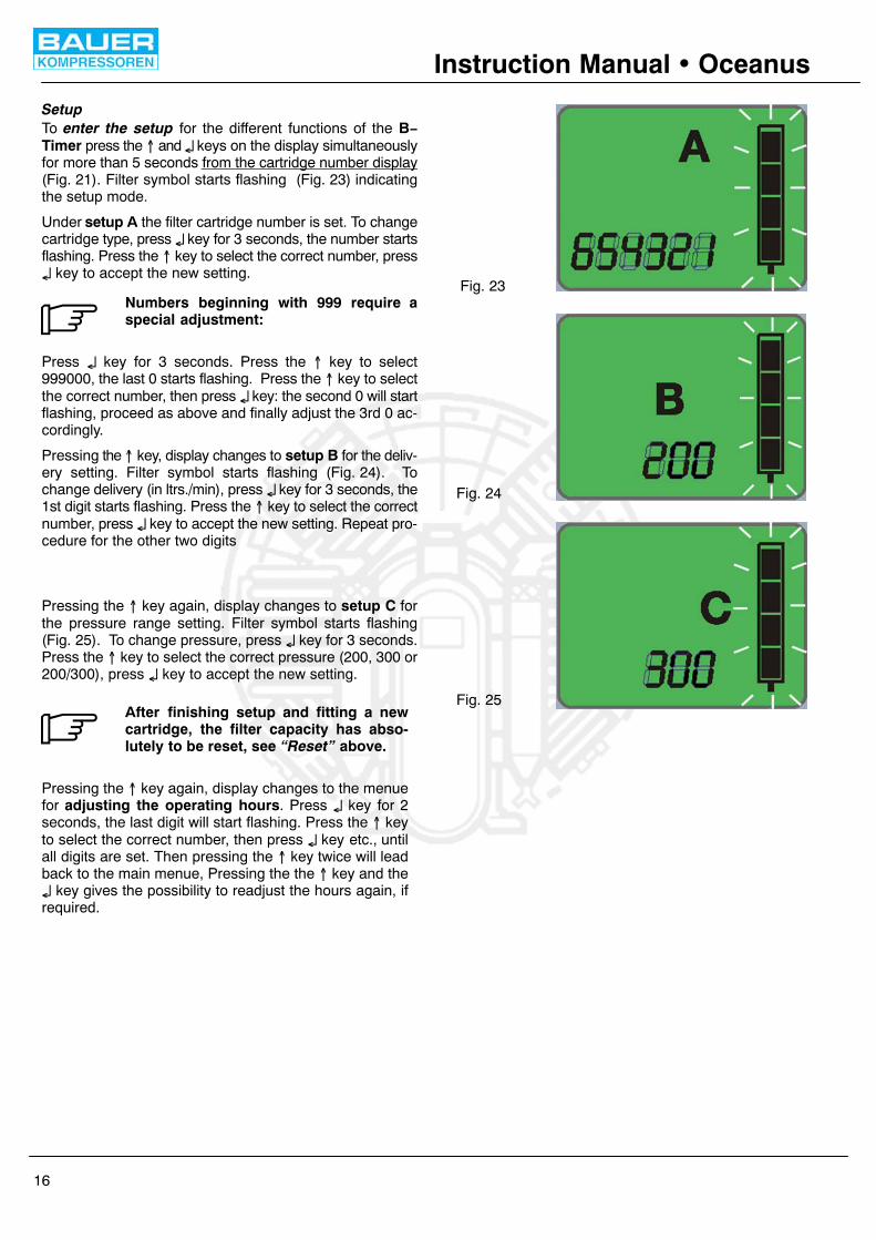
Fig. 23
Fig. 24
Fig. 25
Instruction Manual � Oceanus
16
SetupTo enter the setup for the different functions of the B−Timer press the � and � keys on the display simultaneouslyfor more than 5 seconds from the cartridge number display(Fig. 21). Filter symbol starts flashing (Fig. 23) indicatingthe setup mode.
Under setup A the filter cartridge number is set. To changecartridge type, press � key for 3 seconds, the number startsflashing. Press the � key to select the correct number, press� key to accept the new setting.
Numbers beginning with 999 require aspecial adjustment:
Press � key for 3 seconds. Press the � key to select999000, the last 0 starts flashing. Press the � key to selectthe correct number, then press � key: the second 0 will startflashing, proceed as above and finally adjust the 3rd 0 ac-cordingly.
Pressing the � key, display changes to setup B for the deliv-ery setting. Filter symbol starts flashing (Fig. 24). Tochange delivery (in ltrs./min), press � key for 3 seconds, the1st digit starts flashing. Press the � key to select the correctnumber, press � key to accept the new setting. Repeat pro-cedure for the other two digits
Pressing the � key again, display changes to setup C forthe pressure range setting. Filter symbol starts flashing(Fig. 25). To change pressure, press � key for 3 seconds.Press the � key to select the correct pressure (200, 300 or200/300), press � key to accept the new setting.
After finishing setup and fitting a newcartridge, the filter capacity has abso-lutely to be reset, see “Reset” above.
Pressing the � key again, display changes to the menuefor adjusting the operating hours. Press � key for 2seconds, the last digit will start flashing. Press the � keyto select the correct number, then press � key etc., untilall digits are set. Then pressing the � key twice will leadback to the main menue, Pressing the the � key and the� key gives the possibility to readjust the hours again, ifrequired.

WARNING
WARNING
Instruction Manual � Oceanus
17
4. MAINTENANCE
4.1. MAINTENANCE RECORD
We recommend that all maintenance work is recorded inthe service manual delivered with the compressor, show-ing the date and details of the work carried out. This willhelp to avoid expensive repairwork caused by missedmaintenance work. If it is necessary to claim against thewarranty, it will help to have proof that regular mainten-ance work has been carried out and that the damage hasnot been caused by insufficient maintenance. Please referto section 23 of our general terms and conditions.
4.2. MAINTENANCE INSTRUCTIONS
Always shut down and decom-press the complete system prior tocarrying out any work on the com-pressor.
Never repair pressure lines by sol-dering or welding.
Check the complete system for leakagefrom time to time by brushing all fittingsand couplings with soapy water or spray-ing with leak test spray. Repair any leak-age.
Only use original spare parts for main-tenance or repair work.
Change TRIPLEX longlife cartridge ac-cording to chapter 4.4.4.!
The used cartridge must be disposed ofaccording to local regulations.
Maintenance of drive motor/engine ac-cording to manufacturer’s operating in-structions.
4.3. MAINTENANCE SCHEDULE
The maintenance schedule is contained in the servicemanual delivered with every compressor unit.
4.4. MAINTENANCE WORK
This chapter contains the maintenance work as well as ashort functional description for each component.
4.4.1. LUBRICATION
TYPE OF OIL
For proper care and maintenance of the compressor,using the correct oil is of vital importance. Depending onthe application of the compressor the requirementsplaced on the oil are:− low deposits− no carbonizing effect, especially in the valves− good anti−corrosive properties− emulsification of the condensate in the crankcase− physiological and toxicological suitability.Due to the thermal load on the compressor only high qual-ity oil should be used. You are recommended to restrictoils to those which have been approved by us and arelisted in our lubricating oil list.
The current oil list is provided in theannex, chapter 8. Order this list regularlythrough the BAUER Technical ServiceDepartment.
For operation under difficult conditions such as continu-ous running and/or high ambient temperatures we recom-mend the use of BAUER high performance compressoroils, only, according to the oil list. These oils are tested inour compressors and have proved excellent quality underambient temperatures between +5 °C (41 °F) and +45 °C(113 °F). For lower temperatures, a heating device is re-quired which is capable of pre−heating the crankcase upto +5 °C (41 °F).
For operation under less severe conditions, for intermit-tent operation, or operation with long idle periods we canalso recommend mineral compressor oils which are suit-able for operation under ambient temperatures between+5 °C (41 °F) and +35 °C (95 °F). Here also, pre−heatingis required for lower temperatures.
OIL LEVEL CHECK
Check oil level daily prior to putting compressor into oper-ation. Check using oil dipstick.Take care that dip stick is inserted completely. Note thatthe oil level must be between minimum and maximum dip-stick markings (see Fig. 26).
Oil level must not decrease below min.mark but also not exceed max. mark asthis will cause excessive lubrication ofcompressor and result in valves sootingup.
OIL CHANGE INTERVALS
Mineral oils every 1,000 operating hours,at least annually
Synthetic oils every 2,000 operating hours,at least biennially
OIL CAPACITY
Junior II approx. 360 ml

Instruction Manual � Oceanus
18
OIL PACKAGES
BAUER compressor oil is available in various quantities,refer to oil list in chapter 8.
OIL CHANGE
− Run compressor warm.− Remove oil dipstick.− Drain oil while still warm by means of oil drain plug. Re-
place the sealing, reinstall drain plug and tighten well.− Refill with oil through the oil filler neck.− Oil level is checked with oil dipstick, oil level is correct
if at upper mark.
Fig. 26 Oil dipstick markings
min.
max.
CHANGING THE OIL TYPE
To avoid severe damage to the compres-sor unit when changing the oil type, thefollowing measures should be strictlyadhered to:
− Drain oil completely while still warm.
− Check valves, coolers, separators, purifiers, and allpneumatic tubes and hoses for deposits.
If deposits are detected, perform the following:− Change or clean valves, coolers, separators, purifiers,
and all pneumatic tubes and hoses from deposits.
− Fill compressor with the new oil.
− After approx. 100 operating hours check lubricating oilfor degree of contamination, and change oil again ifnecessary.
− Top up compressor and perform subsequent oilchanges with same oil, only.
4.4.2. INTAKE FILTER
DESCRIPTION
A dry micronic filter is used to filter intake air (Fig. 27).
Fig. 27 Intake filter
1 Knurled nut2 Plastic cap3 Micronic filter cartridge4 O−ring5 Opening
5
4
3
2
1
INTAKE FILTER MAINTENANCE
Filter cartridge must be changed at regular intervals ac-cording to schedule in the service booklet.
− Remove knurled nut (1) and take off plastic cap (2). Re-move filter cartridge (3).
− Clean filter housing inside with a damp cloth. Take careto prevent dust from entering intake pipe.
− Replace O−ring (4) if damaged.
− Insert a new filter element and fasten with cap and nut.
TELESCOPIC INTAKE TUBE
The telescopic intake tube has to be inserted in opening5, Fig. 27. It is necessary to ensure clean air. Petrol drivenbreathing air compressor units are fitted with a telescopicintake tube supplied with the unit. The use of it is also rec-ommended for electric power driven units.

Instruction Manual � Oceanus
19
4.4.3. INTERMEDIATE SEPARATOR
DESCRIPTION
An intermediate separator is mounted on the compressorbetween 2nd and 3rd stage. It is designed to remove waterand oil accumulating due to cooling the compressed me-dium down after the compression process.
Separation is achieved by means of centrifugal action pro-vided by a vortex plate.
INTERMEDIATE SEPARATOR MAINTENANCE
Proper operation will rely on the intermediate separatorbeing properly serviced.
Open drain tap (1, Fig. 28) and drain off condensate every15 to 30 minutes during operation.
Fig. 28 Condensate drain taps
1 2 3
4.4.4. FILTER SYSTEM P21
DESCRIPTION
The air leaving the final stage is cooled in the after−coolerto approx. 10 − 15 °C (18 − 27 °F) above ambient tempera-ture and then enters filter system P21 with TRIPLEX long-life cartridge (Fig. 29).
Fig. 29 Filter system P21
1 10
2
3
4
5
7
6
8
9
11
1 Filter inlet2 Jet pipe3 Filter head4 Final pressure safety valve5 Housing6 Chamber separator7 Cartridge8 Filter outlet9 Pressure maintaining valve10 Condensate drain tap11 Condensate outlet
The filter assembly consists of separator and cartridgechamber. In the separator surrounding the cartridgechamber liquid oil and water particles are reliably separ-ated from the compressed medium by a pipe nozzle.Residual oil and water vapors are then removed by theTRIPLEX longlife cartridge. The quality of the breathingair produced conforms to DIN EN 12021.

WARNING
Instruction Manual � Oceanus
20
CARTRIDGE SAFETY BORE
The filter system P21 is designed to prevent pressurizingin the absence of the filter cartridge. A bore provided in thefilter bottom is sealed air−tight only if the cartridge is inplace (Fig. 30).
No pressure build−up without cartridge!
Without cartridge the venting bore is not sealed, the air es-capes into the atmosphere, no pressure can be built upand thus it is ensured, that unfiltered air is not supplied tothe consuming device.
The venting bore is also used to check the O−rings on thecartridge pin. If air is leaking out of the venting bore eventhough a cartridge is installed, the O−rings are eitherbroken or were damaged on installation.
Remove and check cartridge. If necessary replace car-tridge or O−rings.
Fig. 30 Safety bore
Venting bore
No cartridge Cartridge installed
LIFETIME
The filter system is subject to dy-namic load. It is designed for a cer-tain number of load cycles, which
originate from an abrupt pressure loss at condensatedrain (1 load cycle i.e. condensate drain = 1 depres-surization, 1 pressurization). The filter housing hasto be inspected internally by an expert after havingreached 1/4 of the determined number of load cycles.The inspections have to be arranged by the operator.After reaching the max. number of load cycles the fil-ter assembly must be replaced, otherwise the hous-ing may burst due to material fatigue.
The max. number of load cycles for the P21 Central FilterAssembly is 4,000 if operated at the max. allowable pres-sure difference range of 330 bar (4,700 psi). For a pres-sure difference of 225 bar (3,200 psi) the max. no. of loadcycles is 35,000.
To avoid exceeding the max. number of load cycles the op-erating hours should be recorded in the service manual.On condition that a max. number of four cycles per houris not exceeded (condensate is drained every 15 minutes)
the max. number of operating hours is 1,000 for 330 barunits, and 8,750 for 225 bar units.
GENERAL INSTRUCTIONS FOR FILTER MAINTEN-ANCE
− Depressurize system before starting any mainten-ance work.
− Dry inside of filter housing with a clean cloth before in-stalling new cartridge and check for corrosion. Changeif necessary.
− Lubricate threads and O−rings as well as threadedpart of cartridge with white petrolatum DAB 9 order no.N19091 or WEICON WP 300 white order no. N19752.
− Record number of pressure bottles and/or operatinghours to ensure exact attention to maintenance inter-vals.
− Change cartridge before reactivating a compressorunit after out−of−service periods of more than 3months.
− Leave cartridge in the filter as long as unit is out of ser-vice.
− Keep all condensate drain valves and taps closed.Keep a minimum pressure of approx. 50 to 80 bar (700to 1,100 psi) within the system to prevent moistureentering the compressor piping and filter system.
− The nozzle type separator of the TRIPLEX filter sys-tem is maintenance−free besides the regular conden-sate drainage.
CONDENSATE DRAINAGE
Drain condensate from separator and cartridge chamberregularly by slowly opening drain taps (2 and 3, Fig. 28)− before changing cartridge− before each filling procedure− during filling procedure every 15 minutes.Slowly open left tap first, then right tap approx. 1/3 turn tothe left, until condensate is completely drained. The tapsclose by spring pressure, if necessary tighten by hand tomake sure they are completely air−tight.
FILTER CARTRIDGES
New filter cartridges are vacuum−packed and can bestored for two years (refer to date on the cartridge). A de-fective vacuum package cannot protect the cartridge ap-propriately against environmental influences during stor-age. Should the package be damaged, do not use the car-tridge.To avoid any danger to your health or damage to your unit,change used up cartridges in good time.Never fill used up cartridges yourself! The filter materialwas chosen specifically by BAUER−KOMPRESSORENfor each kind of application.Pay attention to cleanliness an hygiene when changingthe filter.
FILTER SERVICE LIFETIME
The average weight (without package) of a new cartridgeand the increase in weight can be checked with appropri-

WARNING
Instruction Manual � Oceanus
21
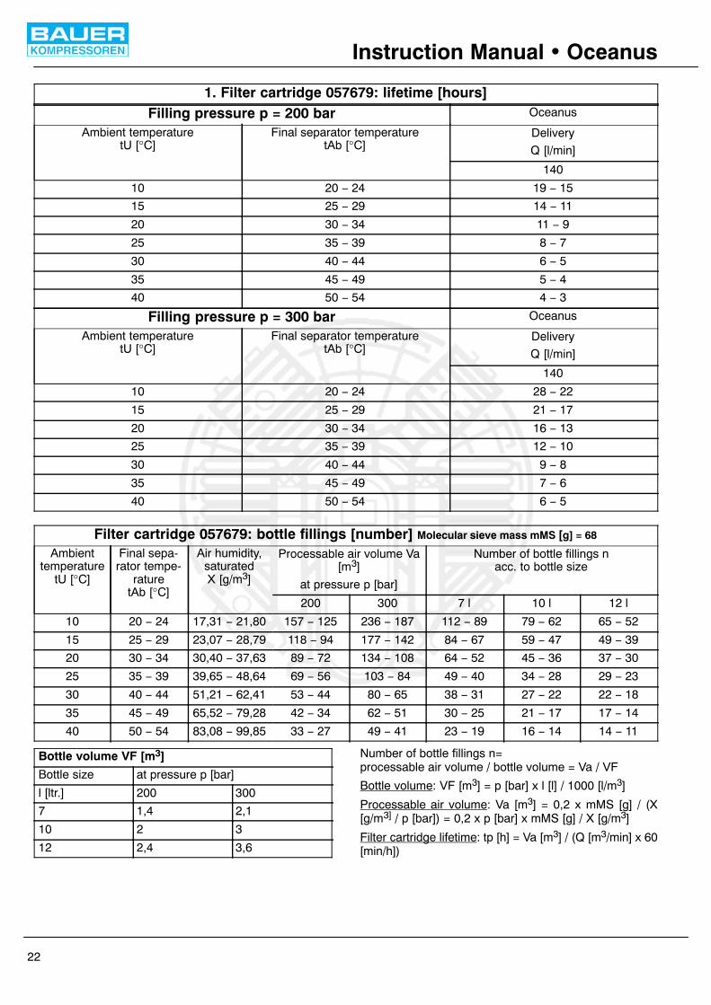
ate weighing scales. Due to inevitable production toler-ances, there may be small differences compared to thegiven data.The number of operating hours or the amount of possiblebottle fillings per filter cartridge can be determined by thetables on page 22 and 23 taking into consideration theambient temperature and the cartridge used.These tables contain calculated cartridge lifetime data,that refer to defined and constant operating conditions.Tolerances at bottle fillings and different operating tem-peratures can lead to considerable divergences com-pared to data given, which therefore can only serve as ref-erence values for the user.Cartridge 057679 is the normal TRIPLEX−cartridge forelectric units.Filling weight: 191 g; Saturation weight 205 g.Example: at an ambient temperature of 20°C, 36 to 4510−ltr−bottles can be filled with a TRIPLEX−cartridge,which is equivalent to 12 to 15 compressor operatinghours at a filling pressure of 200 bar.On compressor units with petrol engines only use car-tridge, part no. 059183 to dry, de−oil and remove CO.Filling weight: 217 g; Saturation weight 229 g.Example: at an ambient temperature of 20°C, 31 to 3810−ltr−bottles can be filled with this cartridge, which isequivalent to between 10 and 13 operating hours at a fill-ing pressure of 200 bar.
The longer service life of the cartridge ata filling pressure of 300 bar is annihilatedby the larger volume of filled air per
bottle, therefore the possible number of bottle fillingsstays the same at different pressures.
CARTRIDGE CHANGE
For safety reasons only CO re-moval cartridges part no. 059183should be used on compressor
units with petrol engine. On units with electric engineeither CO removal cartridge part no. 059183 orTRIPLEX cartridge part no. 057679 can be used.
Units with petrol engine are deliveredwith CO removal cartridge part no.059183 as standard, units with electric
engine with TRIPLEX cartridge part no. 057679. Whenchanging from electric engine to a petrol engine alsoreplace cartridge part no. 057679 with cartridge partno. 059183.
Never remove replacement cartridgefrom packaging prior to actual use other-wise highly sensitive molecular sieve will
absorb water vapour from surrounding air and car-tridge saturated and thus be ruined.
− Prior to changing the filter cartridge, drain condensateand depressurize filter system completely by openingcondensate drain valves.
− Remove filter head (3, Fig. 29).
− Extract old cartridge and insert a new one.
− Screw in filter head to the stop without use of force.
The used cartridge must be disposed ofaccording to local regulations.
FILLING VALVE MAINTENANCE
To protect filling valve against contamination a sinteredmetal filter is screwed in the filling valve body.
Remove filter insert and clean, if heavily soiled replace, asfollows (refer to maintenance schedule, 4.3.):− Unscrew pressure gauge from filling valve body.
− Screw off sintered metal filter with a suitable screwdriver.
− To clean filter element, the best method is to use hotsoapy water and to blow dry with compressed air. Re-place if heavily soiled.
− Screw in filter element,.
− Seal pressure gauge with PTFE tape or Loctite 243and screw in tight to desired position.
Instruction Manual � Oceanus
22
1. Filter cartridge 057679: lifetime [hours]Filling pressure p = 200 bar Oceanus
Ambient temperaturetU [°C]
Final separator temperaturetAb [°C]
Delivery
Q [l/min]
140
10 20 − 24 19 − 15
15 25 − 29 14 − 11
20 30 − 34 11 − 9
25 35 − 39 8 − 7
30 40 − 44 6 − 5
35 45 − 49 5 − 4
40 50 − 54 4 − 3
Filling pressure p = 300 bar Oceanus
Ambient temperaturetU [°C]
Final separator temperaturetAb [°C]
Delivery
Q [l/min]
140
10 20 − 24 28 − 22
15 25 − 29 21 − 17
20 30 − 34 16 − 13
25 35 − 39 12 − 10
30 40 − 44 9 − 8
35 45 − 49 7 − 6
40 50 − 54 6 − 5
Filter cartridge 057679: bottle fillings [number] Molecular sieve mass mMS [g] = 68
Ambienttemperature
tU [°C]
Final sepa-rator tempe-
raturetAb [°C]
Air humidity,saturatedX [g/m3]
Processable air volume Va[m3]
at pressure p [bar]
Number of bottle fillings nacc. to bottle size
200 300 7 l 10 l 12 l
10 20 − 24 17,31 − 21,80 157 − 125 236 − 187 112 − 89 79 − 62 65 − 52
15 25 − 29 23,07 − 28,79 118 − 94 177 − 142 84 − 67 59 − 47 49 − 39
20 30 − 34 30,40 − 37,63 89 − 72 134 − 108 64 − 52 45 − 36 37 − 30
25 35 − 39 39,65 − 48,64 69 − 56 103 − 84 49 − 40 34 − 28 29 − 23
30 40 − 44 51,21 − 62,41 53 − 44 80 − 65 38 − 31 27 − 22 22 − 18
35 45 − 49 65,52 − 79,28 42 − 34 62 − 51 30 − 25 21 − 17 17 − 14
40 50 − 54 83,08 − 99,85 33 − 27 49 − 41 23 − 19 16 − 14 14 − 11
Bottle volume VF [m3]
Bottle size at pressure p [bar]
l [ltr.] 200 300
7 1,4 2,1
10 2 3
12 2,4 3,6
Number of bottle fillings n=processable air volume / bottle volume = Va / VF
Bottle volume: VF [m3] = p [bar] x l [l] / 1000 [l/m3]
Processable air volume: Va [m3] = 0,2 x mMS [g] / (X[g/m3] / p [bar]) = 0,2 x p [bar] x mMS [g] / X [g/m3]
Filter cartridge lifetime: tp [h] = Va [m3] / (Q [m3/min] x 60[min/h])

Instruction Manual � Oceanus
23
2. Filter cartridge 059183: lifetime [hours]Filling pressure p = 200 bar Oceanus
Ambient temperaturetU [°C]
Final separator temperaturetAb [°C]
Delivery
Q [l/min]
140
10 20 − 24 16 − 13
15 25 − 29 12 − 10
20 30 − 34 9 − 7
25 35 − 39 7 − 6
30 40 − 44 5 − 4
35 45 − 49 4 − 3
40 50 − 54 3 − 3
Filling pressure p = 300 bar Oceanus
Ambient temperaturetU [°C]
Final separator temperaturetAb [°C]
Delivery
Q [l/min]
140
10 20 − 24 24 − 19
15 25 − 29 18 − 14
20 30 − 34 14 − 11
25 35 − 39 10 − 9
30 40 − 44 8 − 7
35 45 − 49 6 − 5
40 50 − 54 5 − 4
Filter cartridge 059183: bottle fillings [number] molecular sieve mass mMS [g] = 58
Ambienttemperature
tU [°C]
Final sepa-rator tempe-
raturetAb [°C]
Air humidity,saturatedX [g/m3]
processable air volume Va[m3]
at pressure p [bar]
Number of bottle fillings nacc. to bottle size
200 300 7 l 10 l 12 l
10 20 − 24 17,31 − 21,80 134 − 106 201 − 160 96 − 76 67 − 53 56 − 44
15 25 − 29 23,07 − 28,79 101 − 81 151 − 121 72 − 58 50 − 40 42 − 34
20 30 − 34 30,40 − 37,63 76 − 62 114 − 92 55 − 44 38 − 31 32 − 26
25 35 − 39 39,65 − 48,64 59 − 48 88 − 72 42 − 34 29 − 24 24 − 20
30 40 − 44 51,21 − 62,41 45 − 37 68 − 56 32 − 27 23 − 19 19 − 15
35 45 − 49 65,52 − 79,28 35 − 29 53 − 44 25 − 21 18 − 15 15 − 12
40 50 − 54 83,08 − 99,85 28 − 23 42 − 35 20 − 17 14 − 12 12 − 10
Bottle volume VF [m3]
Bottle size at pressure p [bar]
l [ltr.] 200 300
7 1,4 2,1
10 2 3
12 2,4 3,6
Number of bottle fillings n=processable air volume / bottle volume = Va / VFBottle volume: VF [m3] = p [bar] x l [l] / 1000 [l/m3]
Processable air volume: Va [m3] = 0,2 x mMS [g] / (X[g/m3] / p [bar]) = 0,2 x p [bar] x mMS [g] / X [g/m3]
Filter cartridge lifetime: tp [h] = Va [m3] / (Q [m3/min] x 60[min/h])

Instruction Manual � Oceanus
24
4.4.5. PRESSURE MAINTAINING VALVE
DESCRIPTION
A pressure maintaining valve is mounted at the outlet ofthe filter system P21.It ensures that pressure is built up in the filter even fromthe start of delivery, thus achieving a constant, optimumfiltration. It will also guarantee proper working conditionsfor the final stage cylinder.
The pressure maintaining valve is adjusted to 150 ±10 bar(2,175 psi).
Fig. 31 Pressure maintaining valve
1
23
MAINTENANCE
The pressure maintaining valve (Fig. 31) is adjusted at thefactory to the required pressure and normally does not re-quire regular maintenance or readjustment. In case of re-adjustment becoming necessary, loosen jam nut (2) andset screw (3). Adjust screw (1) to the required pressureusing a suitable screw−driver.
Clockwise = increase pressureCounter−clockwise = decrease pressure
4.4.6. SAFETY VALVES
DESCRIPTION
All three compressor stages are protected by safetyvalves as follows
1st stage 9 bar (130 psi)2nd stage 80 bar (1,160 psi)
The safety valve for protection of the last stage is mountedon top of the filter system P21 and is adjusted to the oper-ating pressure of the unit (see chapter 1, Technical Data),225 bar (3,200 psi) for the standard units, 330 bar (4,700psi) for models −H or −HU. All safety valves are sealed atthe factory.If one of the intermediate pressure safety valves blows off,the valves in the next stage are not closing properly, af-fording valve check. The cause of the trouble is usually theinlet valve of the next stage. See also chapter 4.4.8.MAINTENANCE
Checking function
The final pressure safety valve has to be checked reg-ularly. For this purpose the safety valve can be ventedmanually. Turn knurled knob on top of the valve clockwiseuntil valve blows off (Fig. 32).This just ensures that the valve is functional and will re-lease pressure in case of a malfunction. To check theblow−off pressure value refer to ”Blow−off pressurecheck”.
Fig. 32 Venting the final pressure safety valve
Venting
Checking blow−off pressure
Check blow−off pressure of the final pressure safety valveregularly, see maintenance schedule chapter 4.3. Pumpunit to final pressure with shut−off valve closed until safetyvalve blows off. Check blow−off pressure of safety valveat pressure gauge. If deviation is 10% or more, replacesafety valve.

Instruction Manual � Oceanus
25
4.4.7. PRESSURE GAUGE
DESCRIPTION
The compressor unit is equipped with a final pressuregauge (Fig. 33). The red marking on it shows the max.allowable operating pressure.
Fig. 33 Final pressure gauge
Mark
MAINTENANCE
We recommend that the final pressure gauge is checkedfrom time to time. For this purpose we have developed aspecial test pressure gauge with an adaptor which im-mediately recognizes any deviations in readings (seeHigh Pressure Accessories Catalogue 8550/..).Slight deviations during operation are normal and can beignored. Excessive inaccuracy will require the pressuregauge to be replaced.
4.4.8. VALVES
DESCRIPTION
The valve heads of the individual stages form the top partof the cylinders. The intake and pressure valves are fittedinside the valve heads. Note that the valves are operatedby the flow of the air.On the suction stroke, the intake valves open and the airflows into the cylinders. At the start of the compressionstroke the intake valve closes and the air opens the pres-sure valve, Fig. 34.Intake and pressure valve of the 1st stage is a plate valve(Fig. 35).
INITIAL OPERATIONAL CHECK
After maintenance work on the valves, valves should bechecked. Note that the intake line to the valve headsshould be warm and outlet piping should be hot. Valvesare then operating properly.
Fig. 34 Valve operation
Intake Pressure
Fig. 35 Valve 1st stage
Intake sidePressure side
Top viewfrom intake filter
to 2nd stage N48
60−
F98

Instruction Manual � Oceanus
26
GENERAL INSTRUCTIONS FOR CHANGING THEVALVES
− Always replace valves as a complete set.
− Observe the correct sequence when fitting togetheragain.
− Check individual components for excessive wear. Ifthe valve seat and valve disks are dented, replace thevalves.
− Valve head screws must be tightened with a torquewrench (see tightening torque values chapter 7.).
− Check the valve space in the valve heads for dirt andclean, if necessary.
− 30 minutes after restarting the compressor stop unit,let it cool down to ambient temperature and retightenvalve studs and cap nuts. Otherwise valves could workloose due to setting of the gaskets.
− Use only satisfactory gaskets and O−rings on reas-sembly.
− After finishing all maintenance work on the valves,turn the compressor manually using the flywheel andcheck whether all items have been correctly installed.
CHANGING THE VALVES OF THE 1ST STAGE
Intake and pressure valves of the 1st stage are combinedin one plate valve under the valve head, see Fig. 36.
1 Valve head2 Gasket3 Plate valve4 O−ring5 Valve head screw6 Washer7 Nut
Fig. 36 Valve head 1st stage
56
7
2
3
1
4
− Loosen two cap nuts from tube connectors at valvehead and safety valve connector and remove inter−cooler.
− Remove four valve head screws (5) from valve head(1). Take off valve head.
− Remove gasket (2) and plate valve (3).
− When re−installing the valve, check that mark ”S” isfacing upwards and towards intake filter side. Thecrossbar of gasket (2) seals the intake opening with re-spect to the two outlet openings of the pressure valve.
CHANGING THE VALVES OF THE 2ND STAGE
Both, pressure and intake valves can be serviced fromoutside, see Fig. 37.− Remove two captive nuts (1) and spring−washers (2).
− Remove plate (3).
− Remove valves (4) and (7) using two screw−drivers asshown in Fig. 39.
− Assemble in reverse sequence. Position spring−washers with curved side facing upwards. Fasten nutsso that plate (3) is parallel to the valve head. Torquewith 10 Nm (1 kpm).
Fig. 37 Valve head 2nd stage
1 Nut2 Spring−washer3 Plate4 Pressure valve5 O−ring6 Valve head7 Intake valve8 Valve head screw
CHANGING THE VALVES OF THE 3RD STAGE
On this valve head, the valves are arranged on the upperand lower side due to the small diameter of the 3rd stage,see Fig. 38.
For removal and installation of the intake valve (4) usespecial tool which is also part of the tool set delivered withthe unit.
Pressure valve (3) is merely inserted into valve head (5).It is sealed by O−ring (2) and fixed to the valve head by bolt(1).

Instruction Manual � Oceanus
27
Fig. 38 Valve head 3rd stage
1 Torque stud2 O−ring3 Pressure valve4 Intake valve5 Valve head6 Valve head cover7 Allen screw8 Gasket
Change intake and pressure valve of 3rdstage together only.
Remove of 3rd stage pressure valve (3) according toFig. 38.
− Unwind torque stud (1) a couple of turns.
− Remove allen screws (7), take off valve head cover (6).
− Put two screwdrivers into the groove of pressure valvebody (Fig. 39). If necessary turn valve loose at firstusing a 13 mm spanner on the flat surfaces.
− Lift out pressure valve (3) together with O−ring (2).
Reinstall pressure valve (3) in reverse sequence:
− Check O−ring for abrasion and replace if necessary.Put O−ring (2) into valve head (5).
− Insert pressure valve (3). Install valve head cover (6).
− Fasten valve head with allen screws (7) and washers(8).
− Screw in torque stud (1) with 20 Nm (2 kpm).
Fig. 39 Removal of 3rd stage pressure valve
4.4.9. COMPRESSOR DRIVE SYSTEM
DESCRIPTION
The compressor is driven by the drive motor through a V−belt. The motor is mounted on the base plate and requiresadjustment for proper V−belt tension.
Improper v−belt tension and adjustmentof the pulleys will result in extreme v−beltabrasion and premature wear.
MAINTENANCE
Checking the drive belt tension
− The best tension for a belt drive is the lowest possible,where the belt under full load does not slip. A roughvalue for this is when the belt deflects 10 mm whenpressed with thumb pressure between the two pulleys(Fig. 40). For best results we recommend our v−belttension meter, part no. N25238.
V−belt tension adjustment
− Slightly loosen motor mounting nuts− Adjust motor until the belt tension is correct (see
Fig. 40).− Tighten motor mounting nuts.− Run motor for approx. 5 minutes. Stop motor, check V−
belt tension, and readjust if required.− Check that after tension adjustment and tightening the
motor mounting nuts, both pulleys are in a straight lineto avoid excessive wear of the V−belt. Hold a straightedge against compressor and motor V−belt pulleys asshown in Fig. 41: edge must be parallel to the v−belt.
Fig. 40 Checking V−belt tension
10 mm
Fig. 41 V−belt pulley adjustment

Instruction Manual � Oceanus
28
4.4.10. ELECTRICAL SYSTEM
DESCRIPTION
This section describes the standard electrical system.
For schematic diagram, see annex.
The electrical equipment of the compressor unit consistsof:− drive motor
− electric control system
To start the electric motor and enable the functioning of theelectric control, the following components are essential:
− main switch and main fuse, both to be installed by thecustomer.
DRIVE MOTOR
The compressor unit is driven by an alternating or a threephase current motor by means of a V−belt.
MOTOR PROTECTION SWITCH (ALTERNATINGCURRENT MOTOR)
Protection of the motor is ensured by the thermic releasesintegrated into the motor protection switch (1, Fig. 42).The response value is preset.The motor is switched onmanually by pressing the 0−I switch to I. For safety of theoperating personnel all voltage carrying parts have a pro-tective cover.
MOTOR PROTECTION SWITCH (THREE−PHASEMOTOR)
The motor is switched on manually by turning the switchto 1 (Fig. 43). It is switched off manually by turning theswitch to 0.
For safety of the operating personnel all voltage carryingparts have a protective cover.
After the switch has shut off by overcur-rent triggering, the motor can be re-started by pressing the start−button not
before the bi−metal in the switch has cooled down.This may last a couple of minutes.
Protection of the motor is ensured by the thermomagneticreleases integrated into the motor protection switch. Theresponse value of the electromagnetic releases (protec-tion against short−circuit) is preset.
Fig. 42 Motor protection switch (alternating current)
1
Fig. 43 Motor protection switch (three−phase motor)
01
MAINTENANCE
For the electrical system no regular maintenance is re-quired.
Instruction Manual � Oceanus
29
4.4.11. COOLING SYSTEM
The cylinders of the compressor block, the intermediatecoolers and the after−cooler are air−cooled.
For this purpose, the compressor is equipped with a fan-wheel connected to the counter−weight at the crankshaftend opposite to the V−belt pulley. It draws the cooling airthrough the fanwheel cover from the surroundings.
Refer to chapter 3. for proper installation and cooling airsupply. For maximum ambient temperature, see Techni-cal Data, chapter 1.

Instruction Manual � Oceanus
30
4.5. TROUBLE−SHOOTING
Trouble Cause Remedy
Drive motor (electric)Motor will not start Electric circuitry faulty Check all fuses, terminal connec-
tions, wire leads, make sure that mo-tor data complies with mains supply
Motor/engine runs eccentrically V−belt worn ReplaceMotor protection switch is switchingoff the unit
Wrong adjustment of the motor pro-tection switch
Set to nominal motor current. Ob-serve temperature compensation(+20 °C =1,0)For ambient temperature+ 10 °C : correction factor 0,94+ 30 °C : correction factor 1,05+ 40 °C : correction factor 1,12
Unsufficient voltage because of weakpower supply
Switch off other consuming devices
Motor protection switch is switchingoff the unit
Power supply cable to long or to thin Use suitable cable
Drive motor (petrol)Motor will not start See motor instructions See motor instructionsMotor runs eccentrically V−belt worn ReplaceMotor stops Low oil level Top up oilDrive systemExcessive v−belt wear (black depo-sits on belt guard)
V−belt tension Re−tighten, see chapter 4.4.9.Pulleys not aligned Re−adjust, see chapter 4.4.9.
CompressorCompressor does not attain finalpressure
Condensate drain valve(s) leaking Tighten and reseal
Final pressure safety valve defective(blows too soon)
Replace safety valve
No cartridge in filter system P21 (airescaping through cartridge safetybore)
Replace cartridge
Vent screw for final pressure safetyvalve not in operating position
To vent, unscrew until completelyopen
Air delivery drops Intake filter soiled Clean or replace filter cartridgePipe coupling leaking Retighten couplingsExcessive wear of 3rd stage piston Replace piston and sleeve of 3rd
stageIntermediate pressure safety valveblows
Intermediate pressure too high be-cause of defective inlet or pressurevalve of the following stage
Check/replace inlet or pressure valve
Safety valve leaking Replace safety valveCompressor overheats Insufficient cooling air Check location; ensure proper coo-
ling air flowAmbient temperature too high Check location; ambient temperature
max. +45 °C (113 °F)Direction of rotation is wrong Correct direction of rotationInlet and pressure valve of one stageis leaking
Check valves, clean/replace if neces-sary
Taste of oil in the air TRIPLEX cartridge saturated Replace cartridgeUnqualified lubricant being used Replace oil with an approved brand

Instruction Manual � Oceanus
31
RemedyCauseTrouble
High oil consumption Piston rings, Pistons or cylindersworn out
Replace defective parts
Intake filter clogged Replace filter cartridgeCompressor too hot Enhance cooling
Air escaping through cartridge safetybore
Cartridge missing Insert cartridgeCartridge installed but O−rings defec-tive
Check/replace O−rings

Instruction Manual � Oceanus
32
5. STORAGE, PRESERVATION
GENERAL
If the compressor is put out of service for more than sixmonths, the unit should be preserved in accordance withthe following instructions: Make sure the compressor iskept indoors in a dry, dust free room. Only cover the com-pressor with plastic if it is certain that no condensation willform under the sheet. Nevertheless, the sheet should beremoved from time to time and the unit cleaned on the out-side. If this procedure cannot be followed and/or the com-pressor is going to be taken out of service for more than2 years, please contact our Technical Service Departmentfor special instructions.
The compressor is not resistant to salt−water! If not in use keep unit in a dryplace.
PREPARATION
Before preserving the compressor unit, run it warm andwhen it reaches the specified service pressure, keep itrunning for approx. 10 minutes.Then carry out the following:− Check all pipes, filters and valves (also safety valves)
for leakage.− Tighten all couplings, as required.− After 10 minutes, open the filling valves or the outlet
valve and run the compressor at the set minimum pres-sure (pressure maintaining valve, see chapter 4.4.5.)for approx. 5 minutes.
− After these 5 minutes, shut the system down. Draincondensate from separators. Depressurize unit. Shutfilling valves.
− Open filters and grease threads.− Ensure that filter cartridge remains in the filter!
This will prevent oil entering filling lines as a result ofpreservation procedures.
− Remove intake filter from manifold and all intake linesfrom valve heads.
− Let compressor unit cool down.
PRESERVING THE COMPRESSOR
− Turn the compressor on and spray a small amount (ap-prox. 10 ccm/0.6 cu. in.) of compressor oil into thevalve head inlet port while the compressor is running.Do not let the compressor warm up too much, to keepoil sticky.
− Shut compressor unit off.− Close all valves.− Place the dust cap onto the inlet port.
PRESERVING THE MOTOR/ENGINE
Preserve the motor/engine according to the instructions ofthe motor/engine manufacturer.
PREVENTIVE MAINTENANCE DURING STORAGE
Run the compressor once every 6 months as describedin the following:
− Remove the dust cap from the inlet port and insert theintake filter.
− Open the filling valves or the outlet valve and let theunit run for approx. 10 minutes or until the pressuregauges indicate the correct values.
− Stop the compressor.− Open condensate drain valves and release com-
pressed air. Close condensate drain valves again.− Carry out preservation procedure according to chapter
”preserving the compressor”
Changing the lube oil for preserving
− After prolonged storage, the oil will age in the com-pressor and engine. It should be drained after 2 yearsat the latest and replaced with fresh oil.
− The stated period can only be attained when the crank-case is sealed during the preservation period in ac-cordance with the preservation requirements.
− After changing the oil, turn the compressor and the en-gine or run them for the required period.
− Check the lubrication of the compressor when puttingthe unit into operation once every six months or whenturning the compressor. The oil pump is functioningproperly when oil can be seen flowing through the sightglass of the oil pressure regulator and if the oil pressuregauge indicates the prescribed pressure.
REACTIVATING THE COMPRESSOR UNIT
− Remove the dust cap from the inlet port and insert theintake filter.
− Check the oil level of the compressor.− Check the motor/engine according to the manufac-
turer’s instructions.− Open the purifier and change all filter cartridges.− Run the compressor warm with open filling valves or
outlet valve for approx. 10 minutes.− Check the oil pressure on the pressure gauge. If there
is any fault, check the lubrication of the compressor.− After 10 minutes, close the filling valves or the outlet
valve and run the unit up to final pressure until the finalpressure safety valve blows.
− Check the inter−pressure safety valves for leakage.− Establish cause of any fault from the trouble−shooting
table, chapter 4.5., and take corrective action.− Stop the system when running properly, the com-
pressor is then ready for operation.

Instruction Manual � Oceanus
33
6. REPAIR INSTRUCTIONS
GENERAL
Preventive maintenance usually involves replacing thevalves, gaskets and sealing rings as well as carrying outthe maintenance work. Repair work can be carried out onthe compressor block to a certain extent but a certain ex-perience and skill is necessary. It should be noted, how-ever, that
− no repair should be carried out on the crankdrive noron the bearings
− safety valves are not repaired but always replacedcompletely.
For many BAUER compressor units, workshop manualsare available through our customer service.
For questions on maintenance and repair, please contactour technical service department.

* Exception: mounting bolts of final pressure safety valve: 10 Nm
Fig. 44 Torque sequence
Instruction Manual � Oceanus
34
7. TABLES
TIGHTENING TORQUE VALUES
Unless otherwise specified in text, the following torque values apply. All valve headscrews require torque wrench tightening! The indicated torque values are valid for boltsin greased condition. Replace self−retaining nuts on reassembly.
Bolt or swrew Thread max. torque
Hex and allen head M 6 10 Nm (7 ft.lbs)
Hex and allen head M 8* 25 Nm* (18 ft.lbs)
Hex and allen head M 10 45 Nm (32 ft.lbs)
Hex and allen head M 12 75 Nm (53 ft.lbs)
Hex and allen head M 14 120 Nm (85 ft.lbs)
Hex and allen head M 16 200 Nm (141 ft.lbs)
Pipe connections (swivel nuts): Finger−tight + 1/2 turn
TORQUE SEQUENCE
Tighten valve head and cylinder bolts/nuts equally in thesequence shown in Fig. 44.Be sure to tighten all parts in cold condition only.
LUBRICATION CHART
Usage Lubricants
Rubber and plastic parts, filter housing threads WEICON WP 300 WHITE part no. N19752 or BAUER special grease part no. 072500
Sealing rings BAUER special grease part no. 072500
Shaft seal (seal)Shaft seal (shaft)
BAUER special grease part no. 072500Klüber SK 01−205
Screws, bolts, threads WEICON ANTI−SEIZE AS 040 P part no. N19753 orequivalent compound with copper or MoS2 additives
For compressor lubricating oils refer to oil list in chapter 8.
ADHESIVE AND SEALANT CHART
Usage Adhesives and Sealants
Screws Loctite 2701
Seals for conical threads Loctite 243
Metal − metal sealsHigh temperature connections, e.g. valve heads,cylinders
Temperature resistant compound, e.g. WACKER E10, part no. N18247
Paper gaskets Loctite FAG 2
TESTING AGENTS
Usage Testing agents
Tube connectors, tubes Leakage test spray, part no. FM0089

Instruction Manual � Oceanus
35
8. ANNEX
• Schematic diagramLubricating oil listParts list

Instruction Manual � Oceanus
36

Hauptsicherung bauseits /Main fuse by customer /Fusible principal coté client
Ein/AusOn/Off
Marche/Arrêt
Schaltplan/Schematic diagram/Schéma électrique
MotorschutzschalterMotor protection switchDisjoncteur
76942−S1
Instruction Manual � Oceanus
37
Schematic diagram motor protection switch, three phase current

Instruction Manual � Oceanus
38

Oil list � Breathing air compressors
GENERAL
After extensive tests with many different kinds of lubricants, we have decided to authorize the following brands of oil foruse in BAUER compressors under the given operating conditions.This list is up to date at the time of printing and will be reviewed continuously. Should your list or your instruction manualbe older, please request the latest edition from BAUER Customer Services. When using any of the oils listed below, pleasefollow the oil change intervals and the oil filling level described for the equivalent BAUER compressor oil in the instructionmanual of your unit.
Oil type Use Ambienttemperature
Brand name Designation TypeA
Breathing air
NNitrox
+5 ...+45 °C
Special Compressor oilPart no. N28355
b) c) S + + +Special Compressor oilPart no. N22138 a) M + − +
Oil type
S synthetic oil
M mineral oil
Application
A approved for breathing air application with BAUER air purification systems
N approved for nitrox application (with BAUER membrane unit, only)
a) oil change every 1000 operating hours
b) oil change every 2000 operating hours
c) oil change every 1000 operating hours in case of nitrox application
Suitability
+ = suitable
− = not suitable

Oil list � Breathing air compressors
TYPE OF OIL
Due to the thermal load on the compressor only high quality oil should be used. You are recommended to restrict oils tothose which have been approved by us and are listed in the instruction manual or in the lubricating list on page 1.
Our compressor units are delivered ex works with lubricating oil filled into the crankcase or as consignment,depending on the model, as follows:
Breathing air compressor units: BAUER Special Compressor oil, part no. N28355
Nitrox compressor units: BAUER Special Compressor oil, part no. N28355
For operation under difficult conditions, such as continuous running and/or high ambient temperatures, we only recom-mend the BAUER special synthetic compressor oils acc. to the list on the previous page. These have proved excellentquality under ambient temperatures between +5 °C and +45 °C. For lower temperatures a compressor heating deviceis required which is capable of pre−heating the unit up to +5 °C.
For operation under less severe conditions, and for intermittent operation, i.e. when the compressor is not used for longerperiods between the operating periods, we also recommend the use of the mineral oil acc. to the list on the previous page.This oil is suitable for ambient temperatures between +5 °C and +45 °C. Here also, a pre−heating device will be requiredif ambient temperatures should fall below +5 °C.
Changing the Oil Type
To avoid severe damage to the compressor unit when changing to another oil type, thefollowing measures should be strictly adhered to.
− Drain mineral oil while still warm.− Check valves, coolers, separators, purifiers and all pneumatic tubes and hoses for deposits.
If deposits are present, perform the following steps:
− Remove deposits or change valves, coolers, separators, purifiers and all pneumatic tubes and hoses.− Change oil filter, if applicable.− Fill compressor with the new oil.− After approx. 100 operating hours, replace oil filter again (if applicable). and change oil.− Top up with same oil type.
OIL CHANGE
Mineral oil every 1000 operating hours, at least annually
Synthetic oil every 2000 operating hours, at least every two years
Oil change volume see compressor unit operating manual
BAUER compressor oil is available in the following quantities:
Oil quantity � Oiltype �
Synthetic oil N28355 Mineral oil N22138
0.5 ltr. bottle part no. N28355−0,5 part no. N22138−0,5
1 ltr. bottle part no. N28355−1 part no. N22138−1
5 ltr. container part no. N28355−5 part no. N22138−5
20 ltr. container part no. N28355−20 part no. N22138−20