Embed Size (px)
Citation preview
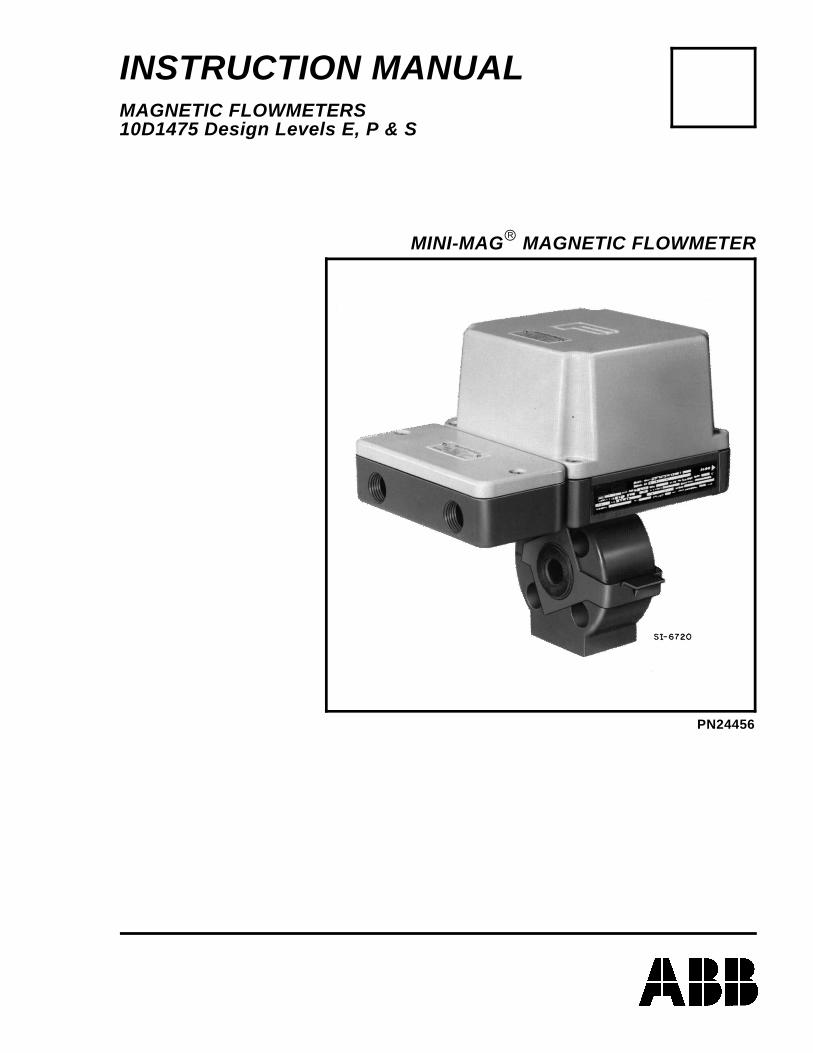
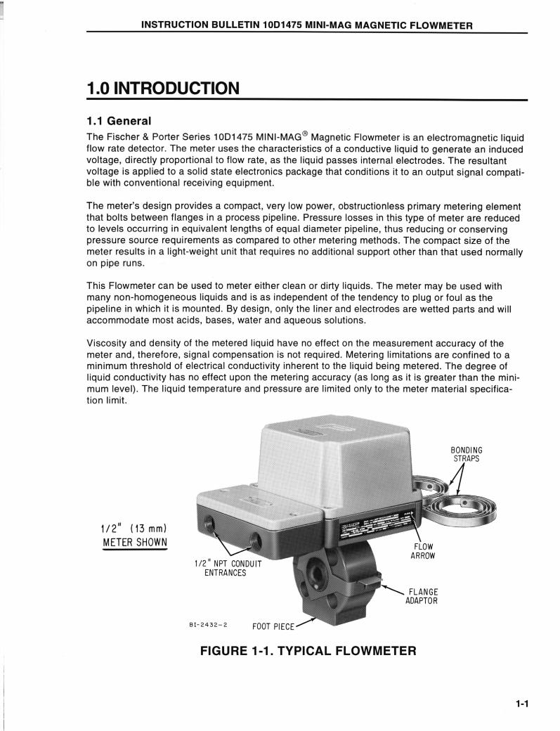
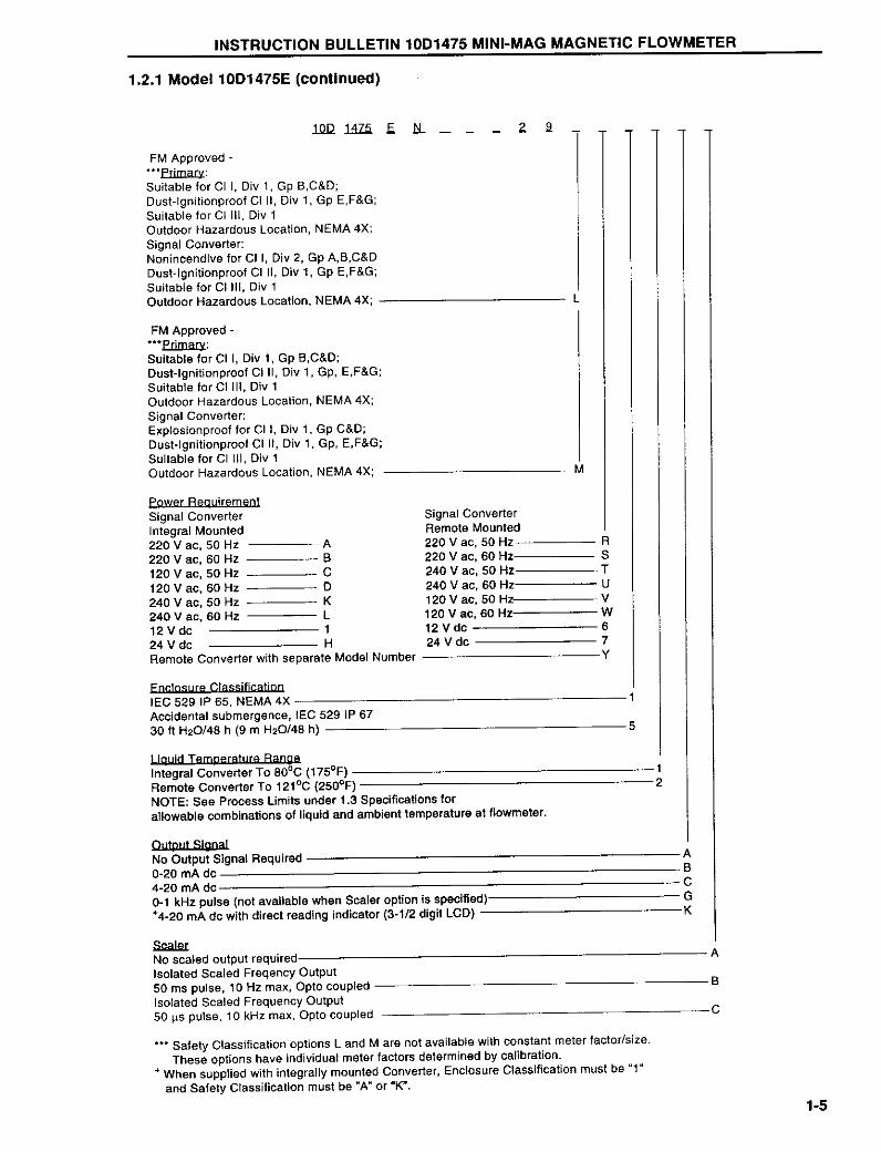
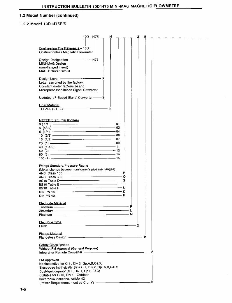
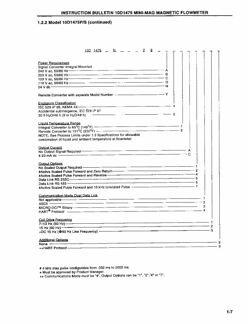
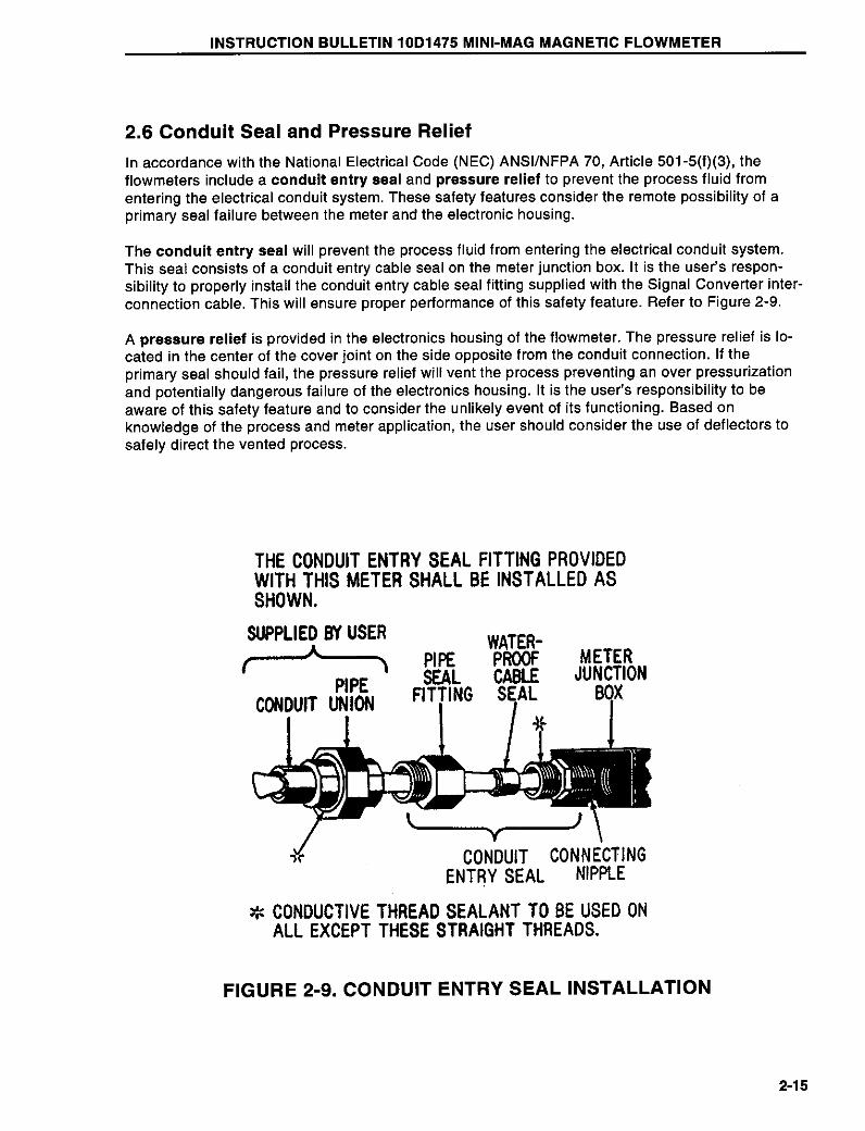
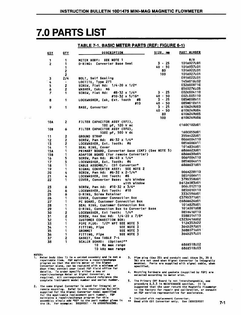
INSTRUCTION MANUALMAGNETIC FLOWMETERS10D1475 Design Levels E, P & S
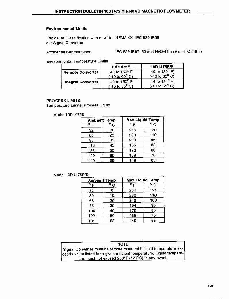
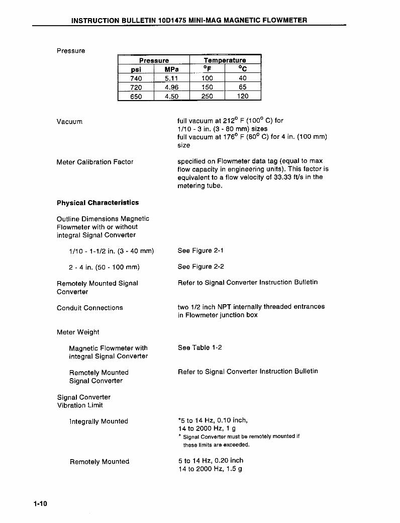
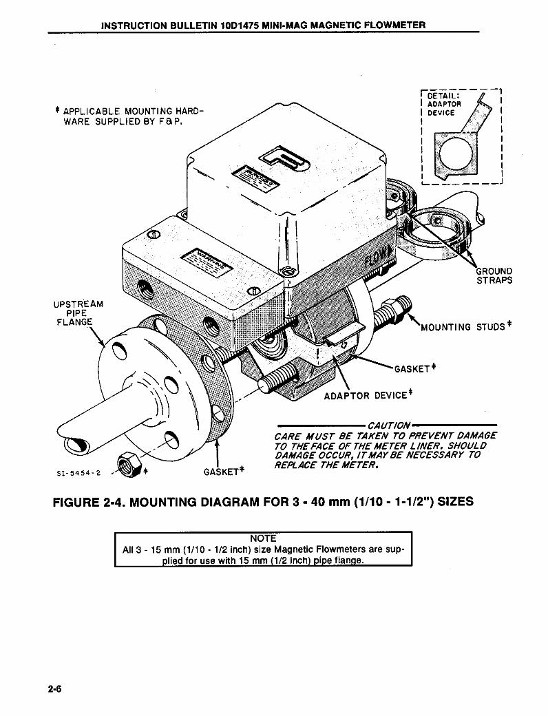
MINI-MAG MAGNETIC FLOWMETER
PN24456
SUPPLEMENT TOMAGNETIC FLOWMETER
INSTRUCTION BULLETINS10D1475E,P & S and 10D1476C & P
THIS INFORMATION SUPPLEMENTS INFORMATION CONTAINED INMAGNETIC FLOWMETER INSTRUCTION BULLETINS
10D1475E,P & S (PN24456) AND 10D1476C & P (PN24453)
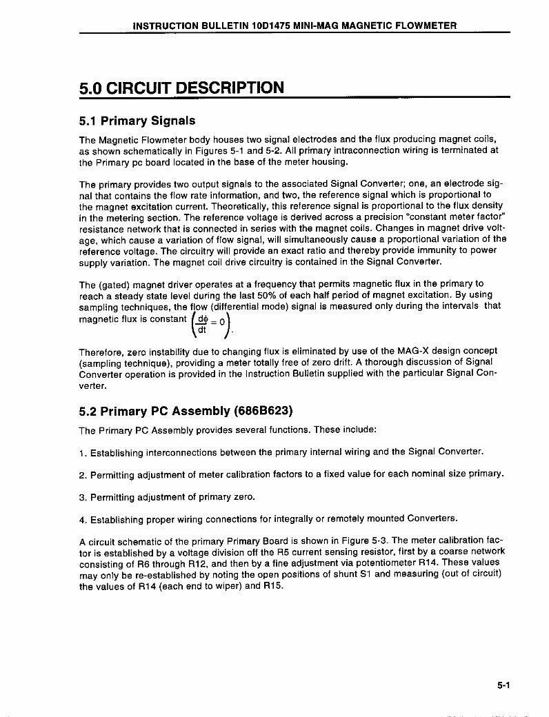
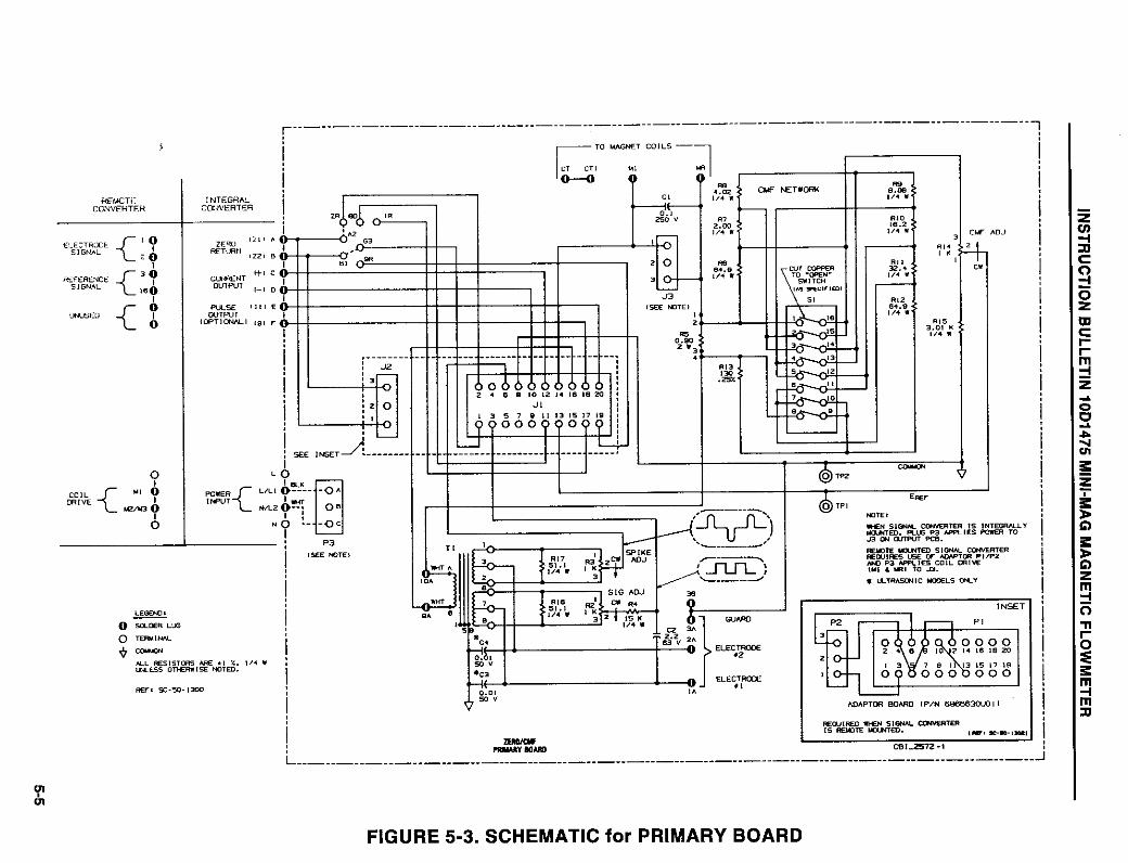
1.0 Circuit Description of 10D1475G AND 10D1476G PrimariesModels 10D1475G and 10D1476G wafer flowmeter primaries each have two flux producing coilswired in series and a pair of diametrically opposed electrodes mounted at 90 degrees to the coil fluxplane. Meter coils are driven with approximately +10 volts of pulsed DC. A precision current sensingnetwork is mounted in series with the coils. The current sense network produces what Bailey-Fischer& Porter refers to as a "Reference Voltage", which is typically +70 millivolts. The reference voltageis directly proportional to the strength of the magnetic field in the measuring tube and must bemeasured by the signal converter since reference voltage variation also produces a proportionalchange in electrode signal voltage, assuming a constant flowing velocity.
Flowmeters of the pulsed DC type operate on the principle that unwanted electrode signals occurwhile the magnetic flux is changing. Accordingly, the signal converters have been designed tosample the electrode voltage only during that portion of the excitation cycle when the magnetic fluxis constant. This occurs during the last 25% or 50% of each half cycle, depending on the type ofsignal converter. Pulsed DC operation of a magmeter system eliminates those variables capable ofcausing drift of the meter zero point.
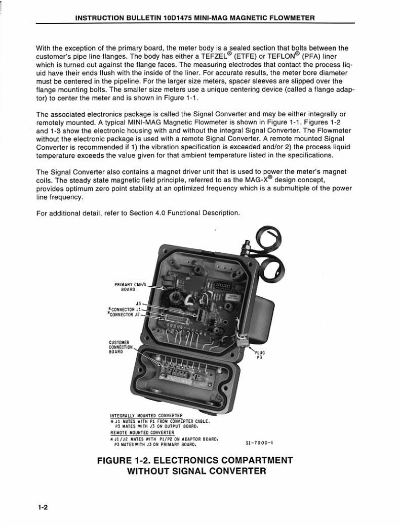
The type of signal converter used in the flowmeter system determines the location and configurationof the circuitry used to produce the reference voltage. Further information regarding signal converteroperations may be found in their respective instruction bulletins.
2.0 Systems Using The CD-1 Signal ConverterAll primaries designed for use with the CD-1 analog signal converter are constructed with a 686B762connection board beneath the converter module. This connection board serves to interconnect theprimary wiring to the converter and also serves to direct converter input/output lines to the customerconnection area. A number of configuration jumpers provide selection of certain terminal functionsas shown in Table 1.
When used with the CD-1, the current sensing network of the 686B762 is active and produces theconverter�s reference voltage. The reference network consists of a 0.9 ohm kelvin resistor and aprecision adjustable resistive divider network. Adjustment of the divider network changes the magni-tude of the reference voltage, thereby forcing the flowmeter system to produce a fixed output for agiven size and flow rate (constant meter factor per size).
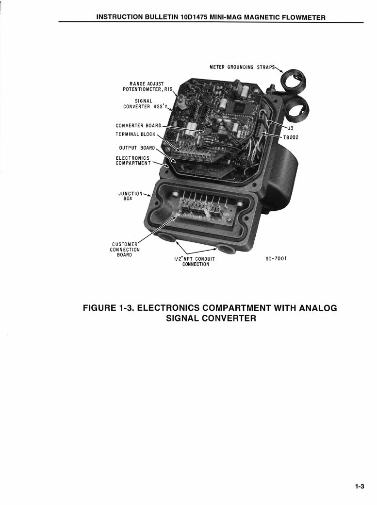
If the signal converter is integrally mounted, the 686B762 assembly has provisions to bring the 4-20mA current output, the scaled pulse output, power connections, and zero return inputs to thecustomer wiring compartment.
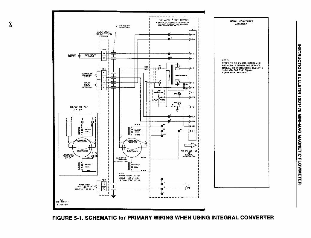
If the CD-1 converter is remotely mounted, then a J1 adaptor plug is installed in the ribbon cableconnector. Also, the converter power plug is installed in P3. These plugs re-direct coil drive,electrode, and reference voltage signals into the meter�s wiring compartment.
Copyright 1998 Elsag Bailey Process Automation (Jul,1998)PN24913 1
TABLE 1. 686B762 BOARD JUMPER FUNCTIONS
JUMPER NUMBER POSITION FUNCTION
J1 1-2 ZERO RETURNJ1 3-4 10 KHZ SIGNALJ1 5-6 REVERSE PULSE SIGNALJ1 7-8 10 KHZ GROUND, ZERO RETURNJ1 9-10 REVERSE PULSE COMMONJ1 2-4, 8-10 REMOTE CONVERTERP4 1-2 INTEGRAL CONVERTERP4 2-3 REMOTE CONVERTER
P5, P6 1-2 M2 MODEP5, P6 2-3 CD-1, XM1000 MODE
3.0 Systems With M2 Signal ConvertersWhen the flowmeter system is fitted with an integrally mounted M2 microprocessor-based converter,a 686B776 circuit board assembly is installed underneath the converter module. This assemblyincorporates the following functional blocks:
• A precision Kelvin current sensing network in series with the coils
• An encapsulated AC coupled buffer preamplifier for each measuring electrode
• An EEPROM for retention of primary span and zero correction factors
• Input/output lines for 4-20 mA current, scaled pulse or data link, contactinputs/outputs (by jumper configuration - Refer to Table 2 and Figure 1)
TABLE 2. 686B776 JUMPER FUNCTIONS
The resistive divider network which produces a converter reference voltage is similar to the onedescribed previously (see CD-1), but in the case of the M2 converter, the reference voltage ismaintained at +70 mV by the signal converter. This results in approximately 200 mA of constant coilcurrent. The EEPROM is programmed with the mathematical corrections necessary to obtain "con-stant meter factor per size".
Systems fitted with remotely mounted M2 converters utilize the 686B762 connection board with aremote J1 adaptor. Through use of jumpers P5 and P6, the current sensing network is disconnectedfrom the coils. No reference voltage is produced within this primary type, but rather at the currentsense network in inside the remote converter housing (see M2 converter IB). The circuit path to thecoils is completed by placing the power connector into P3. Thus, for remote systems using M2converters, a simplified cabling scheme between primary and secondary consists of a circuit com-mon, a safety ground, two electrode leads, and two coil leads.
OPTIONALCOMBINATIONS INPUT/OUTPUT J1 TERMINALS
TO BE CONNECTED
Zero Return / External Totalizer Reset Input 7-8, 4-6 & 3-5Alarm / Opto-coupled Scaled Pulse Output 2-4, 1-3 & 8-10Forward / Reverse Flow Indication Output 2-4, 1-3 & 7-9
Copyright 1998 Elsag Bailey Process Automation (Jul,1998)2 PN24913
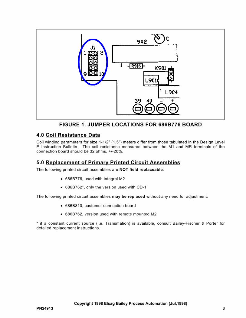
FIGURE 1. JUMPER LOCATIONS FOR 686B776 BOARD
4.0 Coil Resistance DataCoil winding parameters for size 1-1/2" (1.5") meters differ from those tabulated in the Design LevelE Instruction Bulletin. The coil resistance measured between the M1 and MR terminals of theconnection board should be 32 ohms, +/-20%.
5.0 Replacement of Primary Printed Circuit AssembliesThe following printed circuit assemblies are NOT field replaceable:
• 686B776, used with integral M2
• 686B762*, only the version used with CD-1
The following printed circuit assemblies may be replaced without any need for adjustment:
• 686B810, customer connection board
• 686B762, version used with remote mounted M2
* if a constant current source (i.e. Transmation) is available, consult Bailey-Fischer & Porter fordetailed replacement instructions.
Copyright 1998 Elsag Bailey Process Automation (Jul,1998)PN24913 3
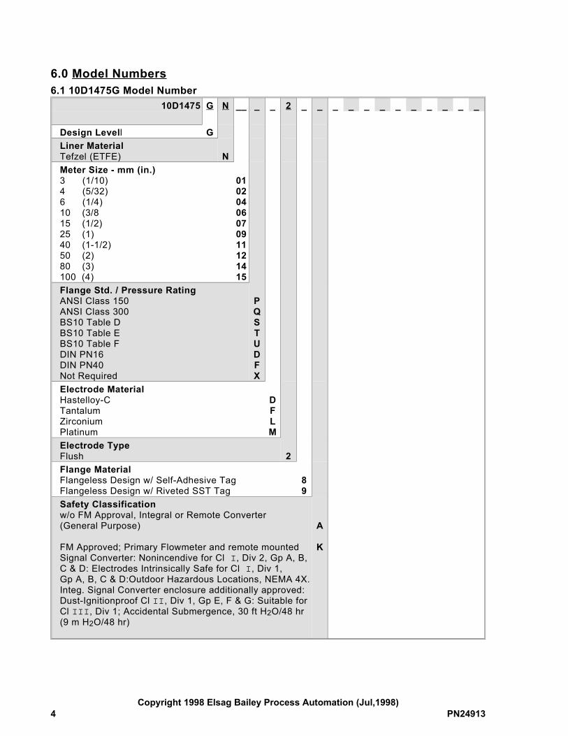
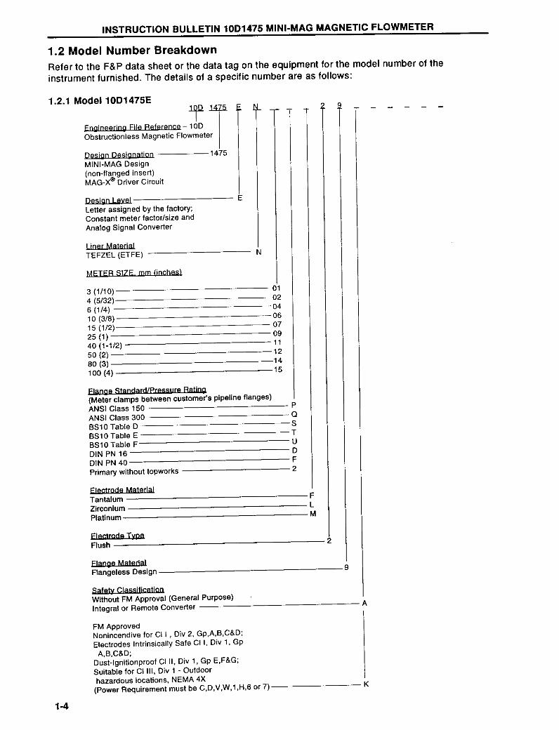
6.0 Model Numbers6.1 10D1475G Model Number
10D1475 G N __ _ _ 2 _ _ _ _ _ _ _ _ _ _ _ _
Design Levell GLiner MaterialTefzel (ETFE) NMeter Size - mm (in.)3 (1/10)4 (5/32)6 (1/4)10 (3/815 (1/2)25 (1)40 (1-1/2)50 (2)80 (3)100 (4)
01020406070911121415
Flange Std. / Pressure RatingANSI Class 150ANSI Class 300BS10 Table DBS10 Table EBS10 Table FDIN PN16DIN PN40Not Required
PQSTUDFX
Electrode MaterialHastelloy-CTantalumZirconiumPlatinum
DFLM
Electrode TypeFlush 2Flange MaterialFlangeless Design w/ Self-Adhesive TagFlangeless Design w/ Riveted SST Tag
89
Safety Classificationw/o FM Approval, Integral or Remote Converter(General Purpose)
FM Approved; Primary Flowmeter and remote mountedSignal Converter: Nonincendive for Cl I, Div 2, Gp A, B,C & D: Electrodes Intrinsically Safe for Cl I, Div 1, Gp A, B, C & D:Outdoor Hazardous Locations, NEMA 4X.Integ. Signal Converter enclosure additionally approved:Dust-Ignitionproof Cl II, Div 1, Gp E, F & G: Suitable forCl III, Div 1; Accidental Submergence, 30 ft H2O/48 hr(9 m H2O/48 hr)
A
K
Copyright 1998 Elsag Bailey Process Automation (Jul,1998)4 PN24913
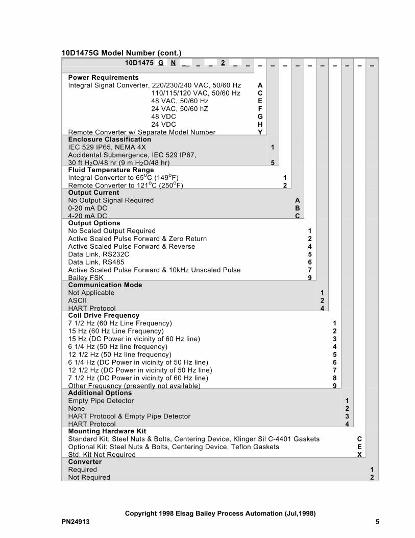
10D1475G Model Number (cont.)10D1475 G N __ _ _ 2 _ _ _ _ _ _ _ _ _ _ _ _
Power RequirementsIntegral Signal Converter, 220/230/240 VAC, 50/60 Hz 110/115/120 VAC, 50/60 Hz 48 VAC, 50/60 Hz 24 VAC, 50/60 hZ 48 VDC 24 VDCRemote Converter w/ Separate Model Number
ACEFGHY
Enclosure ClassificationIEC 529 IP65, NEMA 4XAccidental Submergence, IEC 529 IP67,30 ft H2O/48 hr (9 m H2O/48 hr)
1
5Fluid Temperature RangeIntegral Converter to 65oC (149oF)Remote Converter to 121oC (250oF)
12
Output CurrentNo Output Signal Required0-20 mA DC4-20 mA DC
ABC
Output OptionsNo Scaled Output RequiredActive Scaled Pulse Forward & Zero ReturnActive Scaled Pulse Forward & ReverseData Link, RS232CData Link, RS485Active Scaled Pulse Forward & 10kHz Unscaled PulseBailey FSK
1245679
Communication ModeNot ApplicableASCIIHART Protocol
124
Coil Drive Frequency7 1/2 Hz (60 Hz Line Frequency)15 Hz (60 Hz Line Frequency)15 Hz (DC Power in vicinity of 60 Hz line)6 1/4 Hz (50 Hz line frequency)12 1/2 Hz (50 Hz line frequency)6 1/4 Hz (DC Power in vicinity of 50 Hz line)12 1/2 Hz (DC Power in vicinity of 50 Hz line)7 1/2 Hz (DC Power in vicinity of 60 Hz line)Other Frequency (presently not available)
123456789
Additional OptionsEmpty Pipe DetectorNoneHART Protocol & Empty Pipe DetectorHART Protocol
1234
Mounting Hardware KitStandard Kit: Steel Nuts & Bolts, Centering Device, Klinger Sil C-4401 GasketsOptional Kit: Steel Nuts & Bolts, Centering Device, Teflon GasketsStd. Kit Not Required
CEX
ConverterRequiredNot Required
12
Copyright 1998 Elsag Bailey Process Automation (Jul,1998)PN24913 5
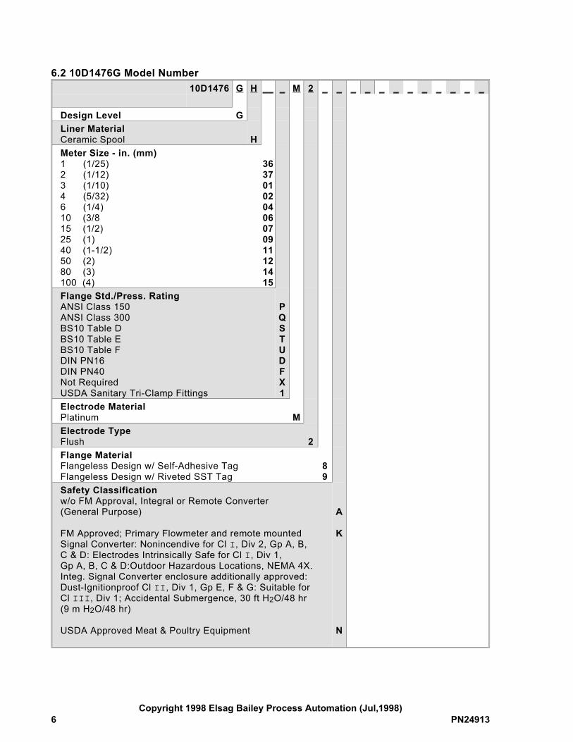
6.2 10D1476G Model Number10D1476 G H __ _ M 2 _ _ _ _ _ _ _ _ _ _ _ _
Design Level GLiner MaterialCeramic Spool HMeter Size - in. (mm)1 (1/25)2 (1/12)3 (1/10)4 (5/32)6 (1/4)10 (3/815 (1/2)25 (1)40 (1-1/2)50 (2)80 (3)100 (4)
363701020406070911121415
Flange Std./Press. RatingANSI Class 150ANSI Class 300BS10 Table DBS10 Table EBS10 Table FDIN PN16DIN PN40Not RequiredUSDA Sanitary Tri-Clamp Fittings
PQSTUDFX1
Electrode MaterialPlatinum MElectrode TypeFlush 2Flange MaterialFlangeless Design w/ Self-Adhesive TagFlangeless Design w/ Riveted SST Tag
89
Safety Classificationw/o FM Approval, Integral or Remote Converter(General Purpose)
FM Approved; Primary Flowmeter and remote mountedSignal Converter: Nonincendive for Cl I, Div 2, Gp A, B,C & D: Electrodes Intrinsically Safe for Cl I, Div 1, Gp A, B, C & D:Outdoor Hazardous Locations, NEMA 4X.Integ. Signal Converter enclosure additionally approved:Dust-Ignitionproof Cl II, Div 1, Gp E, F & G: Suitable forCl III, Div 1; Accidental Submergence, 30 ft H2O/48 hr(9 m H2O/48 hr)
USDA Approved Meat & Poultry Equipment
A
K
N
Copyright 1998 Elsag Bailey Process Automation (Jul,1998)6 PN24913
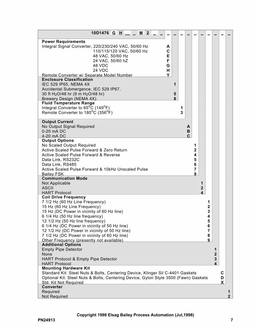
10D1476 G H __ _ M 2 _ _ _ _ _ _ _ _ _ _ _ _
Power RequirementsIntegral Signal Converter, 220/230/240 VAC, 50/60 Hz 110/115/120 VAC, 50/60 Hz 48 VAC, 50/60 Hz 24 VAC, 50/60 hZ 48 VDC 24 VDCRemote Converter w/ Separate Model Number
ACEFGHY
Enclosure ClassificationIEC 529 IP65, NEMA 4XAccidental Submergence, IEC 529 IP67,30 ft H2O/48 hr (9 m H2O/48 hr)Brewery Design (NEMA 4X)
1
58
Fluid Temperature RangeIntegral Converter to 65oC (149oF)Remote Converter to 180oC (356oF)
13
Output CurrentNo Output Signal Required0-20 mA DC4-20 mA DC
ABC
Output OptionsNo Scaled Output RequiredActive Scaled Pulse Forward & Zero ReturnActive Scaled Pulse Forward & ReverseData Link, RS232CData Link, RS485Active Scaled Pulse Forward & 10kHz Unscaled PulseBailey FSK
1245679
Communication ModeNot ApplicableASCIIHART Protocol
124
Coil Drive Frequency7 1/2 Hz (60 Hz Line Frequency)15 Hz (60 Hz Line Frequency)15 Hz (DC Power in vicinity of 60 Hz line)6 1/4 Hz (50 Hz line frequency)12 1/2 Hz (50 Hz line frequency)6 1/4 Hz (DC Power in vicinity of 50 Hz line)12 1/2 Hz (DC Power in vicinity of 50 Hz line)7 1/2 Hz (DC Power in vicinity of 60 Hz line)Other Frequency (presently not available)
123456789
Additional OptionsEmpty Pipe DetectorNoneHART Protocol & Empty Pipe DetectorHART Protocol
1234
Mounting Hardware KitStandard Kit: Steel Nuts & Bolts, Centering Device, Klinger Sil C-4401 GasketsOptional Kit: Steel Nuts & Bolts, Centering Device, Gylon Style 3500 (Fawn) GasketsStd. Kit Not Required
CDX
ConverterRequiredNot Required
12
Copyright 1998 Elsag Bailey Process Automation (Jul,1998)PN24913 7


![User's AXF Manual Magnetic Flowmeter Integral Flowmeter ... · User's Manual Yo kogawa Electric Corporation AXF Magnetic Flowmeter Integral Flowmeter/ Remote Flowtube [Hardware Edition]](https://img.pdfslide.us/doc/110x75/5c40f15893f3c338c3289cbb/users-axf-manual-magnetic-flowmeter-integral-flowmeter-users-manual-yo.jpg)

![User´s AXFA14G/C Manual Magnetic Flowmeter Remote ... · AXFA14G/C Magnetic Flowmeter Remote Converter [Hardware Edition/Software Edition] AXF Magnetic Flowmeter Integral Flowmeter](https://img.pdfslide.us/doc/110x75/5e9c29ae5a06915e2b2224e0/users-axfa14gc-manual-magnetic-flowmeter-remote-axfa14gc-magnetic-flowmeter.jpg)