Embed Size (px)
Citation preview
GR
Electromagnetic flowmeters
Variable area flowmeters
Mass flowmeters
Ultrasonic flowmeters
Vortex flowmeters
Flow controllers
Level measuring instruments
Pressure and temperature
Heat metering
Communications technology
Switches, counters, displays and recorders
Engineering systems & solutions
DIN A4: 7.10028.31.00© KROHNE 06/2005 7.30934.32.00
Short form installation and operating instructions
Universal 3-Beamultrasonic flowmeter UFM 3030 ultrasonic flowmeterUFC 030 ultrasonic flow converterUFS 3000 ultrasonic flow sensor
Subject to change without notice.
2 UFM 3030
General advice on safety • Do not install, operate or maintain this flowmeter without reading, understanding and following
the factory-supplied instructions, otherwise injury or damage may result. • Read these instructions carefully before starting installation and save them for future reference. • Observe all warnings and instructions marked on the product. • Use only mains supply with protective earthing connected. • Do not use the product with removed covers under wet conditions. • Consider handling and lifting instructions to avoid damage. • Install the product securely and stable. • Install and connect cabling proper to exclude damage or harmful situations. • If the product does not operate normally, refer to the service instructions or refer to qualified
KROHNE service engineers. • There are no operator-serviceable parts inside the product.
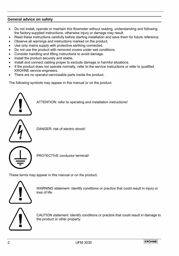
The following symbols may appear in this manual or on the product
ATTENTION: refer to operating and installation instructions!
DANGER: risk of electric shock!
PROTECTIVE conductor terminal!
These terms may appear in this manual or on the product:
WARNING statement: identify conditions or practice that could result in injury or loss of life.
CAUTION statement: identify conditions or practice that could result in damage to the product or other property.
UFM 3030 3
Disclaimer • This document contains important information on the product. KROHNE attempts to be as
accurate and up-to-date as possible but assumes no responsibility for errors or omissions. Nor does KROHNE make any commitment to update the information contained herein. This manual and all other documents are subject to change without prior notice.
• KROHNE will not be liable for any damage of any kind by using its product, including, but not limited to direct, indirect, incidental, punitive and consequential damages.
• This disclaimer does not apply in case KROHNE has acted on purpose or with gross negligence. In the event any applicable law does not allow such limitations on implied warranties or the exclusion of limitation of certain damages, you may, if such law applies to you, not be subject to some or all of the above disclaimer, exclusions or limitations.
• Any product purchased from KROHNE is warranted in accordance with the relevant product documentation and our Terms and Conditions of Sale.
• KROHNE reserves the right to alter the content of its documents, including this disclaimer in any way, at any time, for any reason, without prior notification, and will not be liable in any way for possible consequences of such changes.
Product liability and warranty • Responsibility for suitability and intended use of this ultrasonic flowmeter rests solely with the
user. Improper installation and operation of the flowmeter (system) may lead to loss of warranty.
• In addition, the Terms and Conditions of Sale are applicable and are the basis for the purchase contract.
• If flowmeters need to be returned to KROHNE, please note the information given on the last pages of the installation and operating instructions. KROHNE regrets that they cannot repair or check flowmeter(s) unless accompanied by the completed form (see last pages of the installation and operating instructions).
Items included with order • UFM 3030 ultrasonic flowmeter, comprising of a flow sensor, UFS3000 and a signal converter,
UFC 030 either built together as a compact system or supplied as two separate pieces, in the size as indicated on the packaging box
• Signal cable (only in case of a separate system) • Special tool for opening the converter housing
Documentation supplied • Condensed installation and operating manual • For Ex-units: installation and operating instructions for use in hazardous areas • Service Handbook • Approval documents, unless reproduced in the installation and operating instructions • Report of factory settings of the signal converter • Certificate of system calibration data
4 UFM 3030
System Installation and Start-up 1 Introduction
1.1 Cautions
Only for flowmeters supplied with a voltage over 50 VAC.
Refer all maintenance or service to trained KROHNE service engineers. Mains power shall be disconnected from the product before performing any maintenance. This product is prepared for and can only function with the rated AC mains or DC supply voltage as indicated on the nameplate. For 100 – 240 VAC supplied flowmeters: this product is a Class 1 device (earthed) and requires a correct connection to protective earth. The protective earth conductor of the main power shall be properly connected to the marked protective earth terminal to ensure safety from electric shock for the operator and its environment. For detail refer to this service handbook.
1.2
1.3
Unpacking and inspection
• This product has been thoroughly inspected and tested before shipment and is ready for operation.
• After carefully unpacking, inspect for shipping damage before attempting to operate. If any indication of mechanical damage is found contact immediately the responsible transport service and your local KROHNE representative.
• A simple operating check of the electronics after unpacking and before permanent installation is advisable to ascertain whether it has suffered damage during shipment. Confirm for the correct mains voltage printed on the nameplate. If it differs from the ordered product please contact your local KROHNE representative.
• After connecting to the mains, check if there is any indication on the display and if the backlight of the display is lighted. If not, contact your local KROHNE representative for advice.
System description
The UFM 3030 ultrasonic flowmeter is a precision instrument designed for linear, bi/directional flow measurement of liquids. Flow measurement values can be output via the standard analog and-or pulse/frequency outputs. Via a user friendly operator interface (HMI) the unit can be set up for a wide range of applications. Next to actual volumetric flow measurement the unit can be configured to perform flow totalization (plus, minus and sum). Also measurement and output of the liquid sonic velocity can be configured. Optionally the unit can be set to perform one of the following additional functions: • Calculate and output corrected standard volumetric or mass flow using the external pressure and
temperature inputs • Batching • Heat measurement
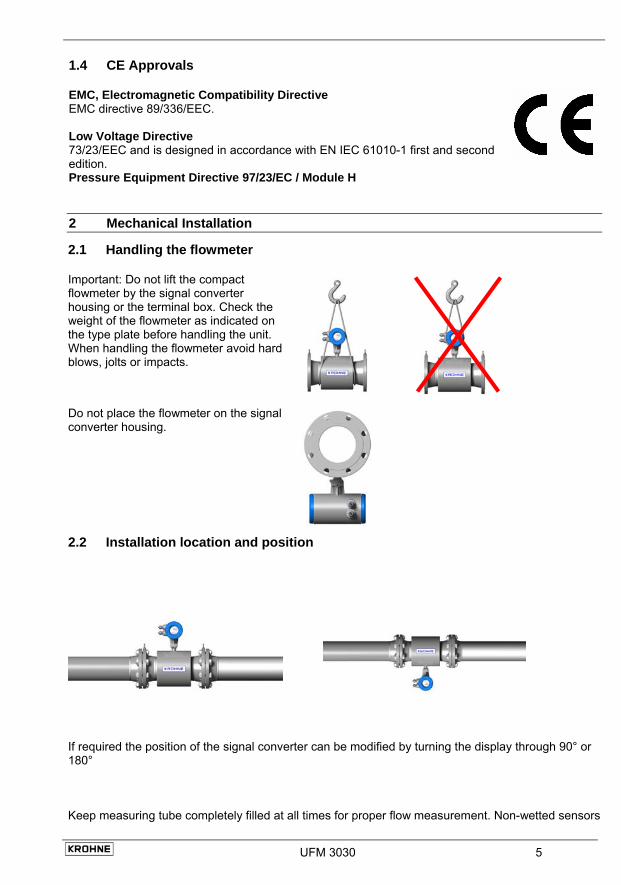
1.4 CE Approvals
EMC, Electromagnetic Compatibility Directive EMC directive 89/336/EEC. Low Voltage Directive 73/23/EEC and is designed in accordance with EN IEC 61010-1 first and second edition.
Pressure Equipment Directive 97/23/EC / Module H
2 Mechanical Installation
2.1 Handling the flowmeter
Important: Do not lift the compact flowmeter by the signal converter housing or the terminal box. Check the weight of the flowmeter as indicated on the type plate before handling the unit. When handling the flowmeter avoid hard blows, jolts or impacts.
Do not place the flowmeter on the signal converter housing.
2.2 Installation location and position
If required the position of the signal converter can be modified by turning the display through 90° or 180° Keep measuring tube completely filled at all times for proper flow measurement. Non-wetted sensors
UFM 3030 5
6 UFM 3030
2.3
show loss of signal. There is no damage when this occurs. Flow direction. The UFM 3030 is a bi-directional flowmeter. Note the indicating arrow for the positive direction on the flowmeter. In case of direct sunlight, we recommend installation of a sunshield to prolong the life of the meter. No direct damage will occur without a sunshield. Do not expose the signal converter to excessive vibration. For this, support the pipeline on either side of the flowmeter. To achieve the specified accuracy, ensure a straight inlet section of 10 × DN (DN = meter size) and an outlet section of 5 × DN. Mixing different fluid products. Install the flowmeter upstream of mixing point or at minimum distance of 30× DN (DN = meter size) downstream of the mixing point, otherwise the flow measurement may be unstable. Ambient temperature all flowmeters: Product temperature compact flowmeter: Product temperature separate flowmeter:
-40 to +65°C/ -40 to +149°F -25 to +140°C/ -13 F to +284°F -25 to +180°C/ -13 to +356°F
a minimum distance between pipe centreline and any adjacent wall of at least 0.5 m (1.6 ft).
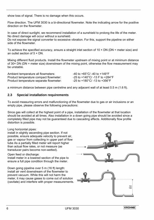
Special installation requirements To avoid measuring errors and malfunctioning of the flowmeter due to gas or air inclusions or an empty pipe, please observe the following precautions: Since gas will collect at the highest point of a pipe, installation of the flowmeter at that location should be avoided at all times. Also installation in a down going pipe should be avoided since a completely filled pipe may not be guaranteed due to cascading affects. Additionally flow profile distortion is possible. Long horizontal pipes: install in slightly ascending pipe section. If not possible, ensure adequate velocity to prevent air, gas or vapour from collecting in upper part of flow tube As a partially filled meter will report higher than actual flow rates, or not measure (as transducer pairs become non-wetted). Open feed or discharge: Install meter in a lowered section of the pipe to ensure a full pipe condition through the meter.
Down going pipeline over 5 m (16 ft) length: install air vent downstream of the flowmeter to prevent vacuum. While this will not harm the meter, it may cause gases to come out of solution (cavitate) and interfere with proper measurements.
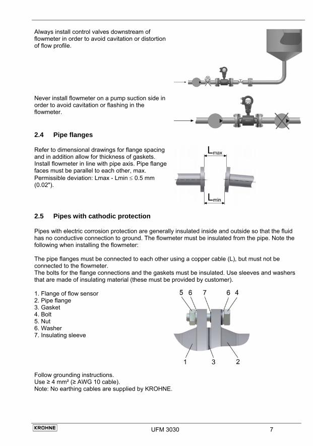
Always install control valves downstream of flowmeter in order to avoid cavitation or distortion of flow profile.
Never install flowmeter on a pump suction side in order to avoid cavitation or flashing in the flowmeter.
2.4 Pipe flanges
Refer to dimensional drawings for flange spacing and in addition allow for thickness of gaskets. Install flowmeter in line with pipe axis. Pipe flange faces must be parallel to each other, max. Permissible deviation: Lmax - Lmin ≤ 0.5 mm (0.02").
2.5 Pipes with cathodic protection
Pipes with electric corrosion protection are generally insulated inside and outside so that the fluid has no conductive connection to ground. The flowmeter must be insulated from the pipe. Note the following when installing the flowmeter: The pipe flanges must be connected to each other using a copper cable (L), but must not be connected to the flowmeter. The bolts for the flange connections and the gaskets must be insulated. Use sleeves and washers that are made of insulating material (these must be provided by customer). 1. Flange of flow sensor 2. Pipe flange 3. Gasket 4. Bolt 5. Nut 6. Washer 7. Insulating sleeve
Follow grounding instructions. Use ≥ 4 mm² (≥ AWG 10 cable). Note: No earthing cables are supplied by KROHNE.
UFM 3030 7
8 UFM 3030
3 Connecting the signal converter
3.1
3.2
3.3
Safety instructions This product is designed for use in accordance with EN IEC 61010-1 for Installation Category 2 and Pollution Degree 2. Hazardous voltages are present within this product during normal operation. The product is designed for Protection Class I and should never be operated without protective earthing. The product shall also never be operated with covers removed unless equivalent protection of the operator and its environment from accidental contact with hazardous internal voltages is provided. Always follow basic and local safety precautions when using this product to reduce risk of injury from electrical shock, spread of fire or other dangerous situations.
Converter terminal box • The converter terminal box is accessible after removing the rear (blind) cover of the electronics
section using the special wrench supplied with the flowmeter. • Do not damage the screw thread and the gasket, never allow dirt to accumulate, and make sure
that the screw thread is well greased, using Teflon grease at all times. A damaged gasket must be replaced immediately!
• Do not cross or loop the cables in the terminal box of the signal converter. Use separate cable entries for power supply and signal cables.
• Special regulations apply to installation in hazardous areas (see installation instructions for hazardous areas).
Power supply connection In case of connection to the mains supply voltage: Environmental conditions • The UFM3030 is designed to operate safe under the following conditions: • Suitable for indoor and outdoor use, the instrument is usable up to protection category IP67
(IEC 60529) • Use up to an altitude of 2000 m above see level • Suitable for an operation ambient temperature range - 40 to +65°C • Suitable for an storage temperature range -40 to + 80°C • Suitable for use in atmospheres with a relative humidity up to 80% • Over voltages up to category II on the main supply voltage ( IEC 60364-4-443) • Connected to protective earth conductor ( Protection Class I) • Rated pollution degree 2
• This instrument is intended for permanent connection to the mains. It is required (for example for service) to mount an external switch or circuit breaker near the product for disconnection from the mains. It must be easily reachable by the operator and marked as the disconnecting device for this product. The switch or circuit breaker has to be suitable for the application and shall also be in accordance with to local (safety) requirements and of the building installation. (IEC 60947-1/-3).
• The protective conductor clamp terminal size M5, press-fitted in the terminal compartment (near the main connection terminals), shall always to be connected to the protective earth conductor of the mains supply. Conductors up to 4 mm² (11 AWG) be connected to this terminal. The diameter of the conductors of the mains supply, including the protective earth conductor shall be in accordance with
the general and local requirements. • It is not allowed to use the protective conductor terminal for any other connection
than the protective earth conductor. • IP 67 is only warranted when using suitable cabling with the cable glands and
covers mounted as specified.
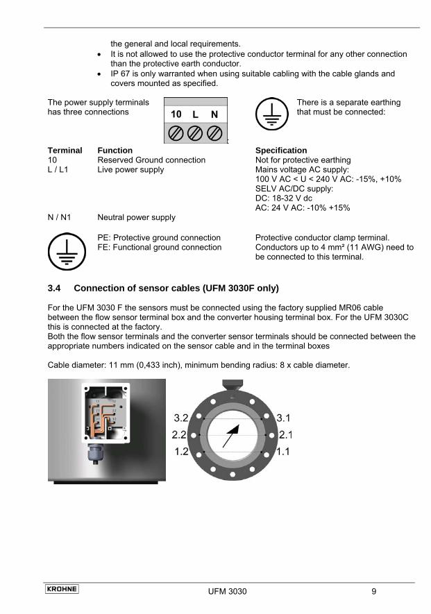
The power supply terminals has three connections
:
There is a separate earthing that must be connected:
Terminal Function Specification 10 Reserved Ground connection Not for protective earthing L / L1 Live power supply Mains voltage AC supply:
100 V AC < U < 240 V AC: -15%, +10% SELV AC/DC supply: DC: 18-32 V dc AC: 24 V AC: -10% +15%
N / N1
Neutral power supply
PE: Protective ground connection FE: Functional ground connection
Protective conductor clamp terminal. Conductors up to 4 mm² (11 AWG) need to be connected to this terminal.
3.4 Connection of sensor cables (UFM 3030F only) For the UFM 3030 F the sensors must be connected using the factory supplied MR06 cable between the flow sensor terminal box and the converter housing terminal box. For the UFM 3030C this is connected at the factory. Both the flow sensor terminals and the converter sensor terminals should be connected between the appropriate numbers indicated on the sensor cable and in the terminal boxes Cable diameter: 11 mm (0,433 inch), minimum bending radius: 8 x cable diameter.
UFM 3030 9
10 UFM 3030
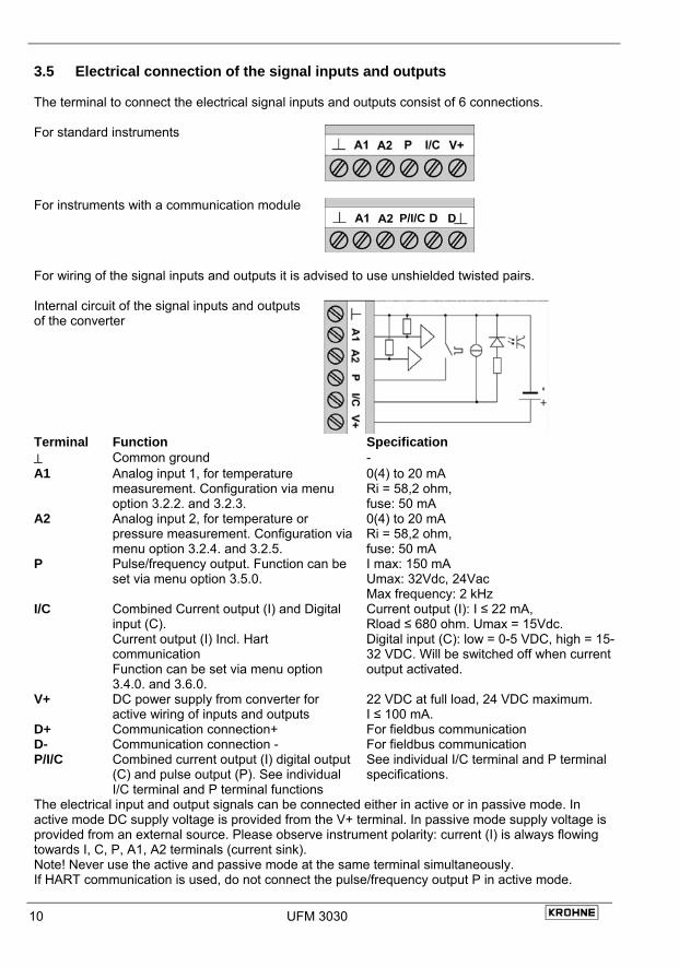
3.5 Electrical connection of the signal inputs and outputs The terminal to connect the electrical signal inputs and outputs consist of 6 connections. For standard instruments
For instruments with a communication module
P/I/C
For wiring of the signal inputs and outputs it is advised to use unshielded twisted pairs. Internal circuit of the signal inputs and outputs of the converter
Terminal Function Specification ⊥ Common ground - A1 Analog input 1, for temperature
measurement. Configuration via menu option 3.2.2. and 3.2.3.
0(4) to 20 mA Ri = 58,2 ohm, fuse: 50 mA
A2 Analog input 2, for temperature or pressure measurement. Configuration via menu option 3.2.4. and 3.2.5.
0(4) to 20 mA Ri = 58,2 ohm, fuse: 50 mA
P Pulse/frequency output. Function can be set via menu option 3.5.0.
I max: 150 mA Umax: 32Vdc, 24Vac Max frequency: 2 kHz
I/C Combined Current output (I) and Digital input (C). Current output (I) Incl. Hart communication Function can be set via menu option 3.4.0. and 3.6.0.
Current output (I): I ≤ 22 mA, Rload ≤ 680 ohm. Umax = 15Vdc. Digital input (C): low = 0-5 VDC, high = 15-32 VDC. Will be switched off when current output activated.
V+ DC power supply from converter for active wiring of inputs and outputs
22 VDC at full load, 24 VDC maximum. I ≤ 100 mA.
D+ Communication connection+ For fieldbus communication D- Communication connection - For fieldbus communication P/I/C Combined current output (I) digital output
(C) and pulse output (P). See individual I/C terminal and P terminal functions
See individual I/C terminal and P terminal specifications.
The electrical input and output signals can be connected either in active or in passive mode. In active mode DC supply voltage is provided from the V+ terminal. In passive mode supply voltage is provided from an external source. Please observe instrument polarity: current (I) is always flowing towards I, C, P, A1, A2 terminals (current sink). Note! Never use the active and passive mode at the same terminal simultaneously. If HART communication is used, do not connect the pulse/frequency output P in active mode.
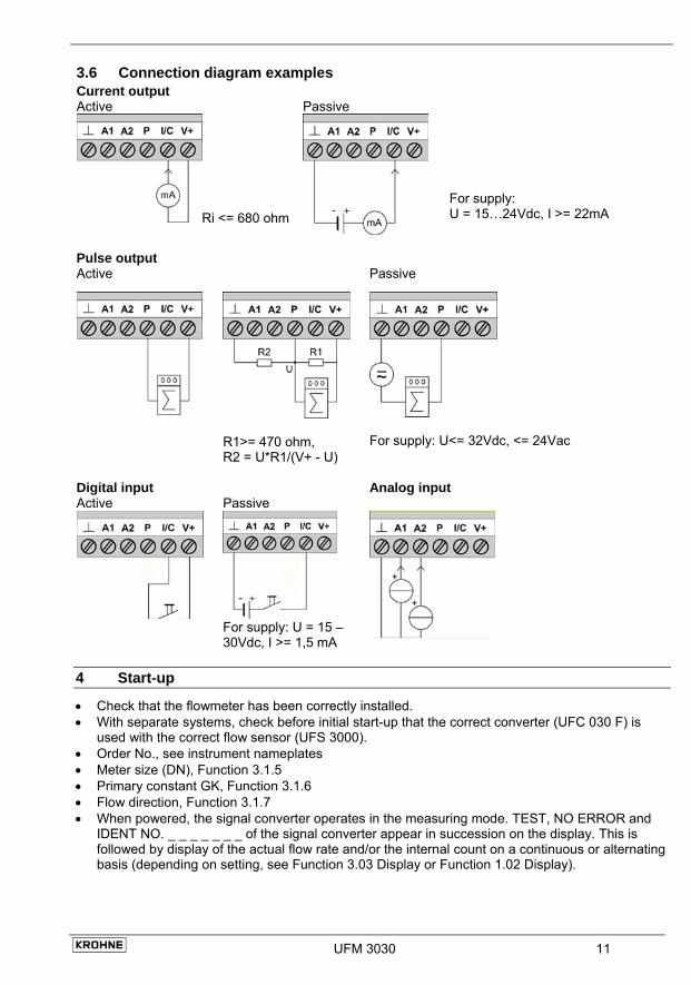
3.6 Connection diagram examples Current output Active
Ri <= 680 ohm
Passive
For supply: U = 15…24Vdc, I >= 22mA
Pulse output Active Passive
R1>= 470 ohm, R2 = U*R1/(V+ - U)
For supply: U<= 32Vdc, <= 24Vac
Digital input Analog input Active
Passive
For supply: U = 15 – 30Vdc, I >= 1,5 mA
4 Start-up
• Check that the flowmeter has been correctly installed. • With separate systems, check before initial start-up that the correct converter (UFC 030 F) is
used with the correct flow sensor (UFS 3000). • Order No., see instrument nameplates • Meter size (DN), Function 3.1.5 • Primary constant GK, Function 3.1.6 • Flow direction, Function 3.1.7 • When powered, the signal converter operates in the measuring mode. TEST, NO ERROR and
IDENT NO. _ _ _ _ _ _ _ of the signal converter appear in succession on the display. This is followed by display of the actual flow rate and/or the internal count on a continuous or alternating basis (depending on setting, see Function 3.03 Display or Function 1.02 Display).
UFM 3030 11
12 UFM 3030
Part B The signal converter 5 Operating the signal converter
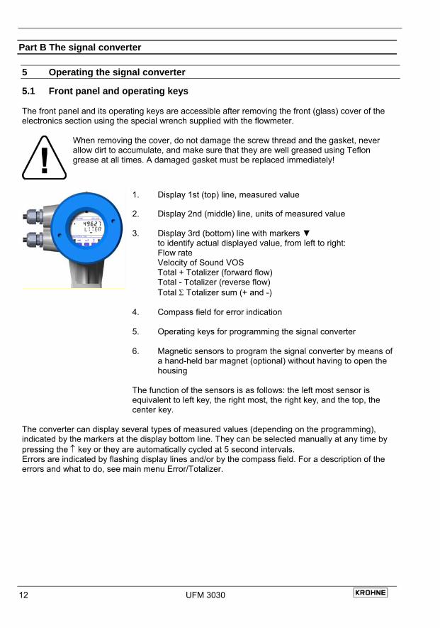
5.1 Front panel and operating keys The front panel and its operating keys are accessible after removing the front (glass) cover of the electronics section using the special wrench supplied with the flowmeter.
When removing the cover, do not damage the screw thread and the gasket, never allow dirt to accumulate, and make sure that they are well greased using Teflon grease at all times. A damaged gasket must be replaced immediately!
1. Display 1st (top) line, measured value
2. Display 2nd (middle) line, units of measured value
3. Display 3rd (bottom) line with markers ▼ to identify actual displayed value, from left to right: Flow rate Velocity of Sound VOS Total + Totalizer (forward flow) Total - Totalizer (reverse flow) Total Σ Totalizer sum (+ and -)
4. Compass field for error indication
5. Operating keys for programming the signal converter
6. Magnetic sensors to program the signal converter by means of a hand-held bar magnet (optional) without having to open the housing
The function of the sensors is as follows: the left most sensor is equivalent to left key, the right most, the right key, and the top, the center key.
The converter can display several types of measured values (depending on the programming), indicated by the markers at the display bottom line. They can be selected manually at any time by pressing the ↑ key or they are automatically cycled at 5 second intervals. Errors are indicated by flashing display lines and/or by the compass field. For a description of the errors and what to do, see main menu Error/Totalizer.
UFM 3030 13
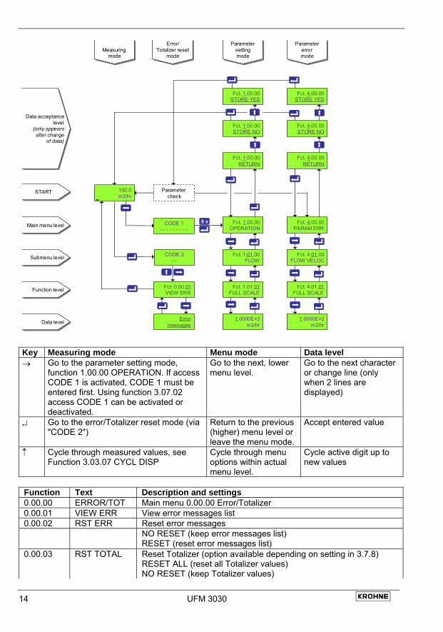
5.2 Menu structure and function of operating keys The menu structure consists of user accessible blocks. • Function block 0 Error/Totalizer reset can be accessed from the measuring mode and provides
detailed information on errors occurred during operation. It allows for fast and easy resetting of the errors and Totalizers.
• Function block 1 Operation contains a subset of options from function block 3, Installation. The options in function block 1 are selected so that the most commonly used functions can be selected quickly from this menu. In most cases only function block 1 needs to be accessed in order to perform the required setting or programming task.
• Function block 2 Test contains all available test functions. This block can be accessed to check proper functioning off all converter hard- and software.
• Function block 3 Installation contains all other set-up parameters for the converter. In general the converter is factory-preset. See Service Handbook for modification instructions.
• Function block 4 Parameter Error becomes active automatically when non-plausible values have been programmed, e.g. a too high a flow rate in too small a diameter. If this is the case menu 4 will indicate that either FULL SCALE or METER SIZE needs to be changed.
The figure below shows the main operation structure of the converter. The cursor or flashing part of the display is shown as underlined text. For a complete overview of the menu see the Service Handbook.
14 UFM 3030
Main menu levelMain menu level
Submenu levelSubmenu level
Function levelFunction level
Data levelData level
Fct. 4.00.00PARAM ERR
Fct. 4.01.00FLOW VELOC
Fct. 4.01.01FULL SCALE
1.0000E+2m3/hr
Fct. 1.00.00OPERATION
Fct. 1.01.00FLOW
Fct. 1.01.01FULL SCALE
1.0000E+2m3/hr
Fct. 1.00.00STORE YES
Fct. 1.00.00STORE NO
Fct. 1.00.00RETURN
Fct. 4.00.00STORE YES
Fct. 4.00.00STORE NO
Fct. 4.00.00RETURN
CODE 2- -
100.0m3/hr
Fct. 0.00.01VIEW ERR
Errormessages
Data acceptancelevel
(only appearsafter change
of data)
Data acceptancelevel
(only appearsafter change
of data)
Measuringmode
Measuringmode
Error/Totalizer reset
mode
Error/Totalizer reset
mode
Parametersettingmode
Parametersettingmode
Parametererrormode
Parametererrormode
CODE 1- - - - - - - - -
Parametercheck
9 x
STARTSTART
Key Measuring mode Menu mode Data level → Go to the parameter setting mode,
function 1.00.00 OPERATION. If access CODE 1 is activated, CODE 1 must be entered first. Using function 3.07.02 access CODE 1 can be activated or deactivated.
Go to the next, lower menu level.
Go to the next character or change line (only when 2 lines are displayed)
↵ Go to the error/Totalizer reset mode (via "CODE 2")
Return to the previous (higher) menu level or leave the menu mode.
Accept entered value
↑ Cycle through measured values, see Function 3.03.07 CYCL DISP
Cycle through menu options within actual menu level.
Cycle active digit up to new values
Function Text Description and settings 0.00.00 ERROR/TOT Main menu 0.00.00 Error/Totalizer 0.00.01 VIEW ERR View error messages list 0.00.02 RST ERR Reset error messages NO RESET (keep error messages list)
RESET (reset error messages list) 0.00.03 RST TOTAL Reset Totalizer (option available depending on setting in 3.7.8)
RESET ALL (reset all Totalizer values) NO RESET (keep Totalizer values)
UFM 3030 15
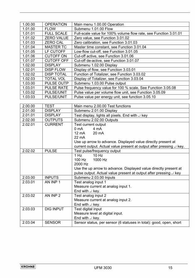
1.00.00 OPERATION Main menu 1.00.00 Operation 1.01.00 FLOW Submenu 1.01.00 Flow 1.01.01 FULL SCALE Full-scale value for 100% volume flow rate, see Function 3.01.01 1.01.02 ZERO VALUE Zero value, see Function 3.01.02 1.01.03 ZERO CAL Zero calibration, see Function 3.01.03 1.01.04 MASTER TC Master time constant, see Function 3.01.04 1.01.05 LF CUTOFF Low-flow cut-off, see Function 3.01.05 1.01.06 CUTOFF ON Cut-off active, see Function 3.01.06 1.01.07 CUTOFF OFF Cut-off de-active, see Function 3.01.07 1.02.00 DISPLAY Submenu 1.02.00 Display 1.02.01 DISP FLOW Display of flow, see Function 3.03.01 1.02.02 DISP TOTAL Function of Totalizer, see Function 3.03.02 1.02.03 TOTAL VOL Display of Totalizer, see Function 3.03.04 1.03.00 PULSE OUTP Submenu 1.03.00 Pulse output 1.03.01 PULSE RATE Pulse frequency value for 100 % scale, See Function 3.05.08 1.03.02 PULSE/UNIT Pulse value per volume flow unit, see Function 3.05.09 1.03.03 PULSE/UNIT Pulse value per energy unit, see function 3.05.10 2.00.00 TEST Main menu 2.00.00 Test functions 2.01.00 DISPLAY Submenu 2.01.00 Display 2.01.01 DISPLAY Test display, lights all pixels. End with ↵ key 2.02.00 OUTPUTS Submenu 2.02.00 Outputs 2.02.01 CURRENT Test current output
0 mA 4 mA 12 mA 20 mA 22 mA Use up arrow to advance. Displayed value directly present at current output. Actual value present at output after pressing ↵ key.
2.02.02 PULSE Test pulse/frequency output 1 Hz 10 Hz
100 Hz 1000 Hz 2000 Hz Use the up arrow to advance. Displayed value directly present at pulse output. Actual value present at output after pressing ↵ key
2.03.00 INPUTS Submenu 2.03.00 Inputs 2.03.01 AN INP 1 Test analog input 1
Measure current at analog input 1. End with ↵ key.
2.03.02 AN INP 2 Test analog input 2 Measure current at analog input 2. End with ↵ key.
2.03.03 DIG INPUT Test digital input Measure level at digital input. End with ↵ key.
2.03.04 SENSOR Sensor status, per sensor (6 statuses in total): good, open, short
16 UFM 3030
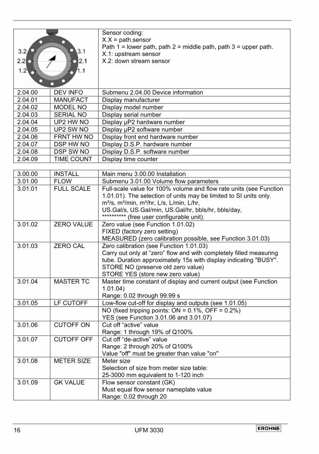
Sensor coding: X.X = path.sensor Path 1 = lower path, path 2 = middle path, path 3 = upper path. X.1: upstream sensor X.2: down stream sensor
2.04.00 DEV INFO Submenu 2.04.00 Device information 2.04.01 MANUFACT Display manufacturer 2.04.02 MODEL NO Display model number 2.04.03 SERIAL NO Display serial number 2.04.04 UP2 HW NO Display µP2 hardware number 2.04.05 UP2 SW NO Display µP2 software number 2.04.06 FRNT HW NO Display front end hardware number 2.04.07 DSP HW NO Display D.S.P. hardware number 2.04.08 DSP SW NO Display D.S.P. software number 2.04.09 TIME COUNT Display time counter 3.00.00 INSTALL Main menu 3.00.00 Installation 3.01.00 FLOW Submenu 3.01.00 Volume flow parameters 3.01.01 FULL SCALE Full-scale value for 100% volume and flow rate units (see Function
1.01.01). The selection of units may be limited to SI units only. m³/s, m³/min, m³/hr, L/s, L/min, L/hr, US.Gal/s, US.Gal/min, US.Gal/hr, bbls/hr, bbls/day, ********** (free user configurable unit).
3.01.02 ZERO VALUE Zero value (see Function 1.01.02) FIXED (factory zero setting) MEASURED (zero calibration possible, see Function 3.01.03)
3.01.03 ZERO CAL Zero calibration (see Function 1.01.03) Carry out only at “zero” flow and with completely filled measuring tube. Duration approximately 15s with display indicating "BUSY". STORE NO (preserve old zero value) STORE YES (store new zero value)
3.01.04 MASTER TC Master time constant of display and current output (see Function 1.01.04) Range: 0.02 through 99.99 s
3.01.05 LF CUTOFF Low-flow cut-off for display and outputs (see 1.01.05) NO (fixed tripping points: ON = 0.1%, OFF = 0.2%)
YES (see Function 3.01.06 and 3.01.07) 3.01.06 CUTOFF ON Cut off “active” value
Range: 1 through 19% of Q100% 3.01.07 CUTOFF OFF Cut off “de-active” value
Range: 2 through 20% of Q100% Value "off" must be greater than value "on"
3.01.08 METER SIZE Meter size Selection of size from meter size table: 25-3000 mm equivalent to 1-120 inch
3.01.09 GK VALUE Flow sensor constant (GK) Must equal flow sensor nameplate value Range: 0.02 through 20
UFM 3030 17
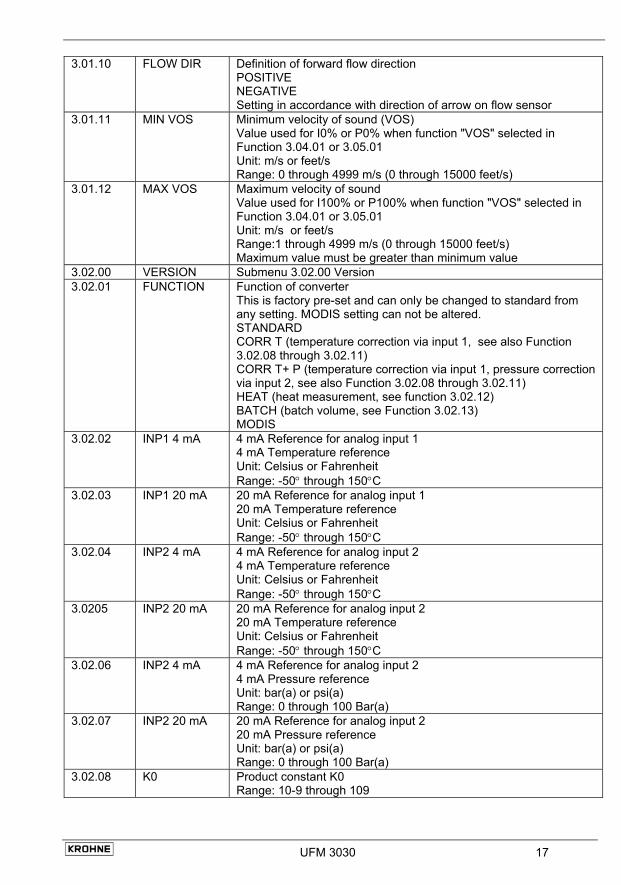
3.01.10 FLOW DIR Definition of forward flow direction POSITIVE NEGATIVE Setting in accordance with direction of arrow on flow sensor
3.01.11 MIN VOS Minimum velocity of sound (VOS) Value used for I0% or P0% when function "VOS" selected in Function 3.04.01 or 3.05.01 Unit: m/s or feet/s Range: 0 through 4999 m/s (0 through 15000 feet/s)
3.01.12 MAX VOS Maximum velocity of sound Value used for I100% or P100% when function "VOS" selected in Function 3.04.01 or 3.05.01 Unit: m/s or feet/s Range:1 through 4999 m/s (0 through 15000 feet/s) Maximum value must be greater than minimum value
3.02.00 VERSION Submenu 3.02.00 Version 3.02.01 FUNCTION Function of converter
This is factory pre-set and can only be changed to standard from any setting. MODIS setting can not be altered. STANDARD CORR T (temperature correction via input 1, see also Function 3.02.08 through 3.02.11) CORR T+ P (temperature correction via input 1, pressure correction via input 2, see also Function 3.02.08 through 3.02.11) HEAT (heat measurement, see function 3.02.12) BATCH (batch volume, see Function 3.02.13) MODIS
3.02.02 INP1 4 mA 4 mA Reference for analog input 1 4 mA Temperature reference Unit: Celsius or Fahrenheit Range: -50° through 150°C
3.02.03 INP1 20 mA 20 mA Reference for analog input 1 20 mA Temperature reference Unit: Celsius or Fahrenheit Range: -50° through 150°C
3.02.04 INP2 4 mA 4 mA Reference for analog input 2 4 mA Temperature reference Unit: Celsius or Fahrenheit Range: -50° through 150°C
3.0205 INP2 20 mA 20 mA Reference for analog input 2 20 mA Temperature reference Unit: Celsius or Fahrenheit Range: -50° through 150°C
3.02.06 INP2 4 mA 4 mA Reference for analog input 2 4 mA Pressure reference Unit: bar(a) or psi(a) Range: 0 through 100 Bar(a)
3.02.07 INP2 20 mA 20 mA Reference for analog input 2 20 mA Pressure reference Unit: bar(a) or psi(a) Range: 0 through 100 Bar(a)
3.02.08 K0 Product constant K0 Range: 10-9 through 109
18 UFM 3030
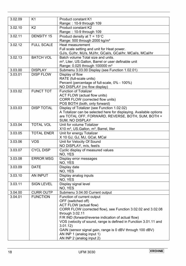
3.02.09 K1 Product constant K1 Range: : 10-9 through 109
3.02.10 K2 Product constant K2 Range: : 10-9 through 109
3.02.11 DENSITY 15 Product density at T = 15°C Range: 500 through 2000 kg/m³
3.02.12 FULL SCALE Heat measurement Full scale setting and unit for Heat power. GJ/s, GJ/hr, MJ/s, MJ/hr, GCal/s, GCal/hr, MCal/s, MCal/hr
3.02.13 BATCH VOL Batch volume Total size and units. m³, Liter, US.Gallon, Barrel or user definable unit Range: 0.025 through 100000 m³
3.03.00 DISPLAY Submenu 3.03.00 Display (see Function 1.02.01) 3.03.01 DISP FLOW Display of flow
RATE (full-scale units) Percent (percentage of full-scale, 0% - 100%) NO DISPLAY (no flow display)
3.03.02 FUNCT TOT Function of Totalizer ACT FLOW (actual flow units) CORR FLOW (corrected flow units) POS BOTH (both, only forward)
3.03.03 DISP TOTAL Display of Totalizer (see Function 1.02.02) A Totalizer can be selected here for displaying. Available options are TOTAL OFF, FORWARD, REVERSE, BOTH, SUM, BOTH + SUM, NO DISPLAY
3.03.04 TOTAL VOL Unit for volume Totalizer X10 m³, US.Gallon, m³, Barrel, liter
3.03.05 TOTAL ENER Unit for energy Totalizer X 10 GJ, GJ, MJ, GCal, MCal
3.03.06 VOS Unit for Velocity Of Sound NO DISPLAY, m/s, feet/s
3.03.07 CYCL DISP Cyclic display of measured values NO, YES
3.03.08 ERROR MSG Display error messages NO, YES
3.03.09 DATE Display date NO, YES
3.03.10 AN INPUT Display analog inputs NO, YES
3.03.11 SIGN LEVEL Display signal level NO, YES
3.04.00 CURR OUTP Submenu 3.04.00 Current output 3.04.01 FUNCTION Function of current output
OFF (switched off) ACT FLOW (actual flow) CORR FLOW (corrected flow), see Function 3.02.02 and 3.02.08 through 3.02.11 F/R IND (forward/reverse indication of actual flow) VOS (velocity of sound, range is defined in Function 3.01.11 and 3.01.12) GAIN (sensor signal gain, range is 0 dBV through 100 dBV) AN INP 1 (analog input 1) AN INP 2 (analog input 2)
UFM 3030 19
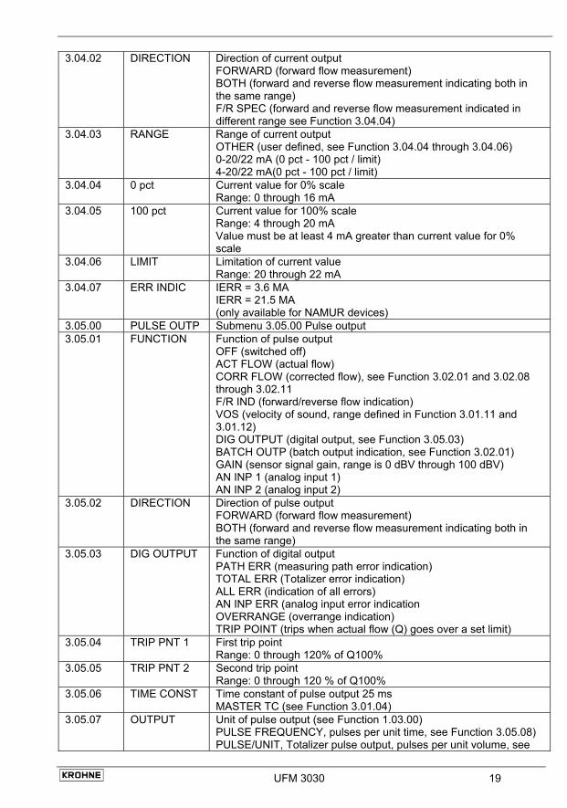
3.04.02 DIRECTION Direction of current output FORWARD (forward flow measurement) BOTH (forward and reverse flow measurement indicating both in the same range) F/R SPEC (forward and reverse flow measurement indicated in different range see Function 3.04.04)
3.04.03 RANGE Range of current output OTHER (user defined, see Function 3.04.04 through 3.04.06) 0-20/22 mA (0 pct - 100 pct / limit) 4-20/22 mA(0 pct - 100 pct / limit)
3.04.04 0 pct Current value for 0% scale Range: 0 through 16 mA
3.04.05 100 pct Current value for 100% scale Range: 4 through 20 mA Value must be at least 4 mA greater than current value for 0% scale
3.04.06 LIMIT Limitation of current value Range: 20 through 22 mA
3.04.07 ERR INDIC IERR = 3.6 MA IERR = 21.5 MA (only available for NAMUR devices)
3.05.00 PULSE OUTP Submenu 3.05.00 Pulse output 3.05.01 FUNCTION Function of pulse output
OFF (switched off) ACT FLOW (actual flow) CORR FLOW (corrected flow), see Function 3.02.01 and 3.02.08 through 3.02.11 F/R IND (forward/reverse flow indication) VOS (velocity of sound, range defined in Function 3.01.11 and 3.01.12) DIG OUTPUT (digital output, see Function 3.05.03) BATCH OUTP (batch output indication, see Function 3.02.01) GAIN (sensor signal gain, range is 0 dBV through 100 dBV) AN INP 1 (analog input 1) AN INP 2 (analog input 2)
3.05.02 DIRECTION Direction of pulse output FORWARD (forward flow measurement) BOTH (forward and reverse flow measurement indicating both in the same range)
3.05.03 DIG OUTPUT Function of digital output PATH ERR (measuring path error indication) TOTAL ERR (Totalizer error indication) ALL ERR (indication of all errors) AN INP ERR (analog input error indication OVERRANGE (overrange indication) TRIP POINT (trips when actual flow (Q) goes over a set limit)
3.05.04 TRIP PNT 1 First trip point Range: 0 through 120% of Q100%
3.05.05 TRIP PNT 2 Second trip point Range: 0 through 120 % of Q100%
3.05.06 TIME CONST Time constant of pulse output 25 ms MASTER TC (see Function 3.01.04)
3.05.07 OUTPUT Unit of pulse output (see Function 1.03.00) PULSE FREQUENCY, pulses per unit time, see Function 3.05.08) PULSE/UNIT, Totalizer pulse output, pulses per unit volume, see
20 UFM 3030
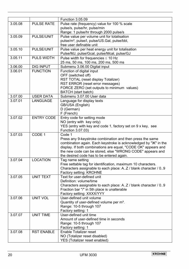
Function 3.05.09 3.05.08 PULSE RATE Pulse rate (frequency) value for 100 % scale
pulse/s, pulse/hr, pulse/min Range: 1 pulse/hr through 2000 pulse/s
3.05.09 PULSE/UNIT Pulse value per volume unit for totalisation pulse/m³, pulse/l, pulse/US.Gal, pulse/bbl, free user definable unit
3.05.10 PULSE/UNIT Pulse value per heat energy unit for totalisation Pulse/MJ, pulse/Gcal, pulse/Mcal, pulse/GJ
3.05.11 PULS WIDTH Pulse width for frequencies ≤ 10 Hz 25 ms, 50 ms, 100 ms, 200 ms, 500 ms
3.06.00 DIG INPUT Submenu 3.06.00 Digital input 3.06.01 FUNCTION Function of digital input
OFF (switched off) RST TOTAL (reset display Totalizer) RST ERROR (reset error messages) FORCE ZERO (set outputs to minimum values) BATCH (start batch)
3.07.00 USER DATA Submenu 3.07.00 User data 3.07.01 LANGUAGE Language for display texts
GB/USA (English) D (German) F (French)
3.07.02 ENTRY CODE Entry code for setting mode NO (entry with key only) YES (entry with key and code 1, factory set on 9 x key, see Function 3.07.03)
3.07.03 CODE 1 Code 1 Press any 9-keystroke combination and then press the same combination again. Each keystroke is acknowledged by "Ж" in the display. If both combinations are equal, "CODE OK" appears and the new code can be stored, else "WRONG CODE" appears and the desired code has to be entered again.
3.07.04 LOCATION Tag name setting Free settable tag for identification, maximum 10 characters. Characters assignable to each place: A..Z / blank character / 0..9 Factory setting: KROHNE
3.07.05 UNIT TEXT Text for user-defined unit Definition: volume/time Characters assignable to each place: A..Z / blank character / 0..9 Fraction bar "/" in 5th place is unalterable Factory setting: XXXX/YYY
3.07.06 UNIT VOL User-defined unit volume Quantity of user-defined volume per m³. Range: 10-5 through 107 Factory setting: 1
3.07.07 UNIT TIME User-defined unit time Amount of user-defined time in seconds Range: 10-5 through 107 Factory setting: 1
3.07.08 RST ENABLE Enable Totalizer reset NO (Totalizer reset disabled) YES (Totalizer reset enabled)
UFM 3030 21
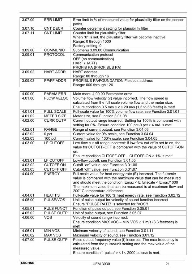
3.07.09 ERR LIMIT Error limit in % of measured value for plausibility filter on the sensor paths.
3.07.10 CNT DECR Counter decrement setting for plausibility filter 3.07.11 CNT LIMIT Counter limit for plausibility filter
When "0" is set, the plausibility filter will become inactive Range: 0 through 1000 Factory setting: 0
3.09.00 COMMUNIC Submenu 3.09.00 Communication 3.09.01 PROTOCOL Communication protocol
OFF (no communication) HART (HART) PROFIB PA (PROFIBUS PA)
3.09.02 HART ADDR HART address Range: 00 through 16
3.09.03 PP/FF ADDR PROFIBUS PA/FOUNDATION Fieldbus address Range: 000 through 126
4.00.00 PARAM ERR Main menu 4.00.00 Parameter error 4.01.00 FLOW VELOC Volume flow velocity (v) value incorrect. The flow speed is
calculated from the full scale volume flow and the meter size. Ensure condition 0.5 m/s ≤ v ≤ 20 m/s (1,5 to 66 feet/s) is met!
4.01.01 FULL SCALE Full-scale value for 100% volume flow rate, see Function 3.01.01 4.01.02 METER SIZE Meter size, see Function 3.01.08 4.02.00 CURR OUTP Current output range incorrect. Setting for 100% is compared with
setting for 0%. Ensure condition 100 pct-0 pct ≥ 4 mA is met! 4.02.01 RANGE Range of current output, see Function 3.04.03 4.02.02 0 pct Current value for 0% scale, see Function 3.04.04 4.02.03 100 pct Current value for 100% scale, see Function 3.04.05 4.03.00 LF CUTOFF Low-flow cut-off range incorrect: If low flow cut-off is set to on, the
value for CUTOFF-OFF is compared with the value of CUTOFF-ON on. Ensure condition CUTOFF-OFF – CUTOFF-ON ≥ 1% is met!
4.03.01 LF CUTOFF Low-flow cut-off, see Function 3.01.05 4.03.02 CUTOFF ON Cutoff “on” value, see Function 3.01.06 4.03.03 CUTOFF OFF Cutoff “off” value, see Function 3.01.07 4.04.00 ENERGY Full scale value for heat energy rate (E) incorrect. The fullscale
value is compared with the maximum value that can be measured and should meet the condition: Emax < E fullscale < Emax/1000 The maximum value that can be measured is at maximum flow and 200° C temperature difference.
4.04.01 HEAT FS Full-scale value for 100 % heat energy rate, see Function 3.02.12 4.05.00 PULSE/VOS Unit of pulse output for velocity of sound function incorrect
Ensure "PULSE RATE" is selected for "VOS"! 4.05.01 PULS FUNCT Function of pulse output, see Function 3.05.01 4.05.02 PULSE OUTP Unit of pulse output, see Function 3.05.07 4.06.00 VOS Velocity of sound range incorrect:
Ensure condition MAX VOS − MIN VOS ≥ 1 m/s (3.3 feet/sec) is met!
4.06.01 MIN VOS Minimum velocity of sound, see Function 3.01.11 4.06.02 MAX VOS Maximum velocity of sound, see Function 3.01.12 4.07.00 PULSE OUTP Pulse output frequency value (f) incorrect. The max frequency is
calculated from the pulse/unit setting and the max value of the measured value. Ensure condition 1 pulse/hr ≤ f ≤ 2000 pulse/s is met.
22 UFM 3030
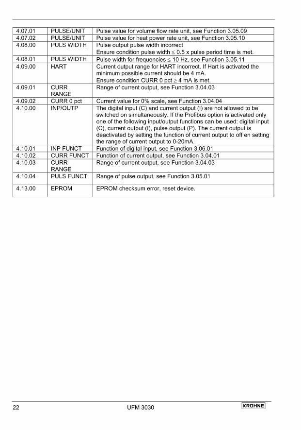
4.07.01 PULSE/UNIT Pulse value for volume flow rate unit, see Function 3.05.09 4.07.02 PULSE/UNIT Pulse value for heat power rate unit, see Function 3.05.10 4.08.00 PULS WIDTH Pulse output pulse width incorrect
Ensure condition pulse width ≤ 0.5 x pulse period time is met. 4.08.01 PULS WIDTH Pulse width for frequencies ≤ 10 Hz, see Function 3.05.11 4.09.00 HART Current output range for HART incorrect. If Hart is activated the
minimum possible current should be 4 mA. Ensure condition CURR 0 pct ≥ 4 mA is met.
4.09.01 CURR RANGE
Range of current output, see Function 3.04.03
4.09.02 CURR 0 pct Current value for 0% scale, see Function 3.04.04 4.10.00 INP/OUTP The digital input (C) and current output (I) are not allowed to be
switched on simultaneously. If the Profibus option is activated only one of the following input/output functions can be used: digital input (C), current output (I), pulse output (P). The current output is deactivated by setting the function of current output to off en setting the range of current output to 0-20mA.
4.10.01 INP FUNCT Function of digital input, see Function 3.06.01 4.10.02 CURR FUNCT Function of current output, see Function 3.04.01 4.10.03 CURR
RANGE Range of current output, see Function 3.04.03
4.10.04 PULS FUNCT Range of pulse output, see Function 3.05.01
4.13.00 EPROM EPROM checksum error, reset device.
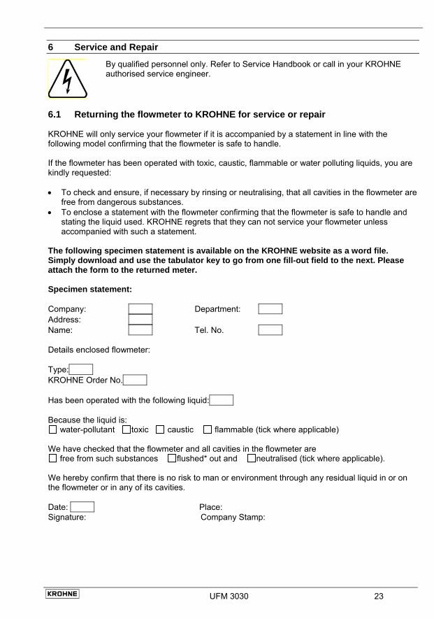
6 Service and Repair
By qualified personnel only. Refer to Service Handbook or call in your KROHNE authorised service engineer.
6.1 Returning the flowmeter to KROHNE for service or repair KROHNE will only service your flowmeter if it is accompanied by a statement in line with the following model confirming that the flowmeter is safe to handle. If the flowmeter has been operated with toxic, caustic, flammable or water polluting liquids, you are kindly requested: • To check and ensure, if necessary by rinsing or neutralising, that all cavities in the flowmeter are
free from dangerous substances. • To enclose a statement with the flowmeter confirming that the flowmeter is safe to handle and
stating the liquid used. KROHNE regrets that they can not service your flowmeter unless accompanied with such a statement.
The following specimen statement is available on the KROHNE website as a word file. Simply download and use the tabulator key to go from one fill-out field to the next. Please attach the form to the returned meter. Specimen statement: Company: Department: Address: Name: Tel. No. Details enclosed flowmeter: Type: KROHNE Order No. Has been operated with the following liquid: Because the liquid is:
water-pollutant toxic caustic flammable (tick where applicable) We have checked that the flowmeter and all cavities in the flowmeter are
free from such substances flushed* out and neutralised (tick where applicable). We hereby confirm that there is no risk to man or environment through any residual liquid in or on the flowmeter or in any of its cavities. Date: Place: Signature: Company Stamp:
UFM 3030 23