Embed Size (px)
Citation preview

excellence in hot water
Installation, Operating andServicing Instructions
HeatMaster®
HeatMaster® 201
20/08/2004 - 66402500


1
INDEX INTRODUCTION
INTRODUCTION 1
Target group 1Symbols 1Certification 1General information and safety instructions 2
USER GUIDE 2
Using the boiler 2Setting the parameters 3
DESCRIPTION 4
Operating principle 4Packing 4 Construction features 4
TECHNICAL SPECIFICATION 6
Effective dimensions 6General characteristics 6Maximum operating conditions 7Domestic hot water performances 7HeatMaster® setting instructions 7
INSTALLATION 8
Boiler room 8Chimney connections 8Hot water connections 9Heating connection 10Electrical connections 10
COMMISSIONING 12
Filling the hot water and heating circuits 12
BURNER FEATURES 12
ACV BG 2000-M modulating premix gas burner 12
MAINTENANCE 14
Service intervals 14Servicing the boiler 14Servicing the safety devices 14Servicing the burner 14Draining the boiler 14
MCBA FOR SPECIALISTS: INSTALLER,SERVICE ENGINEER 15
Pilot mode 15Safety stop (Error mode) 16Setting the parameters 17Entering the code 20Information on the installation 20Communication mode (with code) 21Error mode 21
SPARE PARTS 22
Jackets 22Accessories 22Setting and electrical accessories 22Burner 22
SERVICE RECORD 23
Installation details 23Service notes 23
CERTIFICATION
The appliances carry the “CE” mark, in accordance with thestandards in force in the various countries (European Directives92/42/CEE “Efficiency” and 90/396/CEE “Gas Appliances”). Theyalso carry the labels, “HR+”.
TARGET GROUP
This manual is intended for the use of:- final users of the appliance;- the engineer installing and starting up the appliance;- the engineering and design department;- the installer responsible for servicing or maintaining the appliance.
SYMBOLS
The following symbols are used in these instructions:
Essential instruction for operating the systemcorrectly.
Risk of scalding.
Danger of electrocution.
Essential instruction for personal safety orenvironmental protection.
2
INTRODUCTION
GENERAL INFORMATION AND SAFETY INSTRUCTIONS
IF YOU SMELL GAS:- Immediately shut off the gas supply.- Ventilate the boiler room.- Do not use electrical appliances and do not switch anything on or
off.- Immediately notify your gas company and/or your installer.
General informationThis documentation forms part of the items delivered with theappliance and must be given to the user to keep in a safe place!
This appliance must be serviced and repaired by an approvedinstaller, in accordance with current standards in force.
ACV declines all liability for any damage caused as a result ofincorrect installation or as a result of the use of components orconnections that are not approved by ACV for this application.
Temperatures
This boiler is designed for central heating systemswith a maximum outlet temperature of 90°C.Therefore, the central heating pipelines and theradiators must reach this temperature.
The waste-gas pipe lines must reachtemperatures in excess of 100°C.
The hot water can reach temperatures in excessof 60°C.
Installation
Before installing and commissioning the boiler, firstcarefully read this manual.Position the HeatMaster® according to the safety rules andstandards in force. You must comply with the ventilationrequirements for the room where appliances of this type areinstalled. All air vents must remain unobstructed at all times.
It is prohibited to modify the interior of the appliance in any way,without the manufacturer’s prior written agreement.
ServiceIn order to ensure the appliance operates safely and correctly, it isimportant to have it serviced and reconditioned every year by aninstaller or an approved service company.
FaultsDespite the strict quality standards imposed on its appliances byACV during production, inspection, and transport, faults may occur.Please immediately inform your approved installer about such faults.Remember to give the fault code as it appears on the screen. (Seealso the list of faults on page 16)
Only genuine factory parts may be used as replacement parts.Please go to page 22 for a list of spare parts and their ACVreference numbers.
Note: ACV reserves the right to change the technical characteristicsand specification of its products without notices.
USING THE BOILER
Starting the burnerDuring operation, the burner starts automatically as soon as thetemperature of the boiler is below the set point and goes off whenthis value is reached.
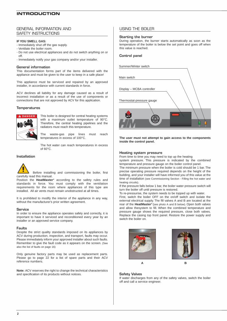
Control panel
The user must not attempt to gain access to the componentsinside the control panel.
Heating system pressureFrom time to time you may need to top up the heatingsystem pressure. This pressure is indicated by the combinedtemperature and pressure gauge on the boiler control panel.The minimum pressure when the boiler is cold should be 1 bar. Theprecise operating pressure required depends on the height of thebuilding, and your installer will have informed you of this value at thetime of installation (see Commissioning Section - Filling the hot water andheating circuits).If the pressure falls below 1 bar, the boiler water pressure switch willturn the boiler off until pressure is restored.To re-pressurise, the system needs to be topped up with water.First, switch the boiler OFF on the on/off switch and isolate theexternal electrical supply. The fill valves A and B are located at therear of the HeatMaster® (see photo A and B below). Open both valvesand allow thesystem to fill. When the combined temperature andpressure gauge shows the required pressure, close both valves.Replace the casing top front panel. Restore the power supply andswitch the boiler on.
Safety ValvesIf water discharges from any of the safety valves, switch the boileroff and call a service engineer.
Main switch
Summer/Winter switch
Thermostat-pressure gauge
Display – MCBA controller
A B

3
USER GUIDE
Reset1
Status T°
1 X
1 X
Mode
Step
2 X
Mode
Store
1 X
Store
1 X
Standby
mode
Stand by mode
SETTING THE PARAMETERS
Setting the temperature of the hot water:(Temperature of the hot water)- Press “Mode”: “PARA” comes up on the screen.- Press “Step”: the first digit is 1 and the last two digits indicate the
current temperature setting for the hot water.- To change this temperature, press the “+” or “-” keys until the
temperature indicated by the last two digits is the desiredtemperature.
- Press “Store” to save the setting.- Press “Mode” twice to return to Standby mode (normal operating
mode).
Enabling and disabling hot water mode:(hot water)- Press “Mode”: “PARA” comes up on the screen.- Press “Step” twice: the first digit is 2 and the last two digits
indicate the current setting:00 = disabled; 01 = enabled.
- To change this parameter, press the “+” or “-” keys until you reachthe desired value:00 = disabled; 01 = enabled.
- Press “Store” to save the setting.- Press “Mode” twice to return to Standby mode (normal operating
mode).
Enabling and disabling central heating mode:(heating)- Press “Mode”: “PARA” comes up on the screen.- Press “Step” three times: the first digit is 3 and the last two digits
indicate the current setting:00 = disabled; 01 = enabled.
- To change this parameter, press the “+” or “-” keys until you reachthe desired value:00 = disabled; 01 = enabled.
- Press “Store” to save the setting.- Press “Mode” twice to return to Standby mode (normal operating
mode).
Setting the temperature of the central heating:(the maximum temperature for the heating circuit)- Press “Mode”: “PARA” comes up on the screen.- Press “Step” four times: the first digit is 4 and the last two digits
indicate the current temperature setting for the central heating.- To change this temperature, press the “+” or “-” keys until the
temperature indicated by the last two digits is the desiredtemperature.
- Press “Store” to save the setting.- Press “Mode” twice to return to Standby mode (normal operating
mode).
Fault:The temperature setting of the appliance and the safety functions of itsparts are constantly monitored by a microprocessor controller (MCBA).In the event of a fault, this MCBA disables the appliance and displaysan error code: the screen flashes and the first character is an “E”followed by the fault code, (see the list of faults on page 16).
Reset the appliance:- Press “Reset” on the screen.- If the fault code appears again, contact your installer.
Setting the temperature of the hot water
4 X
1 X
Mode
Step
2 X
Mode
Store
1 X
Store
1 X
Standby
mode
Stand by mode
Setting the temperature of the central heating
Fault Reset the appliance
3 X
1 X
Mode
Step
2 X
Mode
Store
1 X
Store
1 X
Standby
mode
Stand by mode
Enabling and disabling central heating mode
2 X
1 X
Mode
Step
2 X
Mode
Store
1 X
Store
1 X
Standby
mode
Stand by mode
Enabling and disabling hot water mode

OPERATING PRINCIPLE
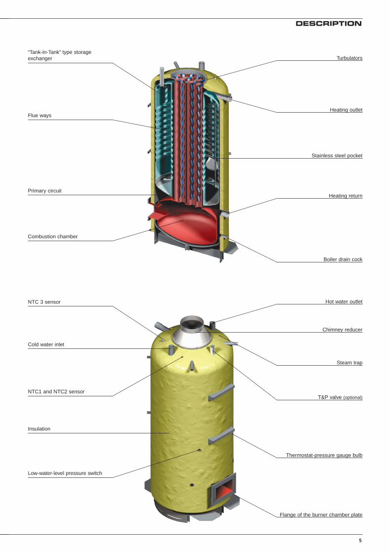
The HeatMaster® is a high performance, direct fired hot waterstorage heater, which has indirect heat transfer due to its Tank-in-Tank construction.
At the heart of the HeatMaster® is a stainless steel cylinder throughwhich the flue tubes pass. This is surrounded by a mild steel shellcontaining the primary water (neutral fluid). The outer shell extendsdown to the combustion chamber and even around the flue tubes.The area of the heat transfer surface is therefore much greater thanthat of standard direct fired water heaters.
A circulating pump fitted to the primary circuit moves the wateraround the tank, heating it faster and maintaining an eventemperature across the primary jacket.
The burner heats the primary water, which indirectly heats thestainless steel tank containing the hot water. As in all Tank-in-Tanksystems, the tank is corrugated over its full height and suspended inthe HeatMaster® by its hot- and cold water connections.
The cylinder expands and contracts during use and this, togetherwith the fact that cold water does not come into contact with theintense heat of the burner flame, means that limescale buildup isprevented.
This scale resistant feature, along with the corrosion resistance ofstainless steel, eliminates the need for sacrifical anodes.
The HeatMaster® has one very major advantage over other directfired water heaters - because it heats the DHW with a primarycircuit, this primary water can be used to provide central heating aswell.
By connecting two, three, four or more HeatMaster® together in amodule, most hot water and heating demands can be met.
Indeed, when used in conjunction with HR and Jumbo hot waterstorage tanks the HeatMaster® can supply even the largest hotwater requirement.
Standard equipmentThe HeatMaster® 201 includes the following parts as standard:
- On/off switch- Summer/Winter switch- MCBA controller, including
• an electronic controller• a low-water-level safety device• a burner modulator
- Primary circulating shunt pump- Primary expansion vessels- Primary safety valve- Pressure and temperature gauge- Drain valve- Body completely insulated in rigid polyurethane foam
PACKING
The HeatMaster® is delivered in 4 separate packages.
• Package No. 1: Foam-insulated body, hydraulic accessories,and control panel.
• Package No. 2: Chimney reducing pipe.• Package No. 3: The jacket.• Package No. 4: The burner and its cover, the door insulation
and the sealing cord.
4
DESCRIPTION
CONSTRUCTION FEATURES
Outer bodyThe outer body containing the primary fluid is made of thick STW 22steel.
TANK-IN-TANK heat exchangerThe ring-shaped inner tank with its large heating surface forproducing domestic hot water is built of Chrome/Nickel 18/10stainless steel. It is corrugated over its full height by an exclusiveproduction process and entirely argon arc welded by the TIG(Tungsten Inert Gas) method.
Combustion gas circuitThe combustion gas circuit is paint-protected and comprises:
• Flue pipesThe HeatMaster® 201 range has 15 steel flue ways with aninside diameter of 64 mm. Each flue way has turbulatorsmade of special stainless steel designed to improve the heatexchange and reduce the flue-gas outlet temperature.
• Combustion chamberThe combustion chamber on HeatMaster® models is entirelywater cooled.
InsulationThe boiler body is fully insulated by rigid polyurethane foam with ahigh thermal insulation coefficient, sprayed on without the use ofCFCs.
CasingThe boiler is covered by a steel jacket which has been scoured andphosphated before being stove enamelled at 220°C.
BurnerModels in the 201 range are always delivered with an ACV BG 2000-M 201 air-gas premix burner.
5
DESCRIPTION
Thermostat-pressure gauge bulb
Flange of the burner chamber plate
Steam trap
T&P valve (optional)
Hot water outlet
Chimney reducer
NTC 3 sensor
Cold water inlet
NTC1 and NTC2 sensor
Insulation
Low-water-level pressure switch
Heating return
Boiler drain cock
Heating outlet
Stainless steel pocket
Turbulators“Tank-in-Tank” type storageexchanger
Primary circuit
Combustion chamber
Flue ways

6
EFFECTIVE DIMENSIONS
The appliances delivered are factory-tested. Upon receipt, remove the packing and check that there is no damage to the appliances. Refer to thedimensions and weights listed below for transport purposes.The jacket is fitted by the installer on site (see the assembly instructions in the wooden protective case).
TECHNICAL SPECIFICATION
A
G
H
250
190
302
338
E
C
D
F
506
B
Type HM 201
Fuel Natural gas/propane
Heating Hot water
Maximum Input kW 60 - 220 60 - 240
Maximum Output kW 56.4 - 200.2 56.4 - 218.4
Maintenance loss at 60°C as rated value % 0.3
Total capacity L 641
Primary circuit capacity L 241
Heating connection Ø 2”
Hot water connection Ø 2”
Chimney connection Ø mm 250
Hot water tank heat exchange surface m2 5.30
Weight empty Kg 550
Pressure drop primary circuit mbar 240
GENERAL CHARACTERISTICS
A mm B mm C mm D mm E mm F mm G mm H mm
HeatMaster® 201 2085 300 1020 1320 1020 600 1383 590
250
190
250302
338
E
C
F
506
G
H
250
190
250302
338
E
C
D
F
506

7
TECHNICAL SPECIFICATION
MAXIMUM OPERATING CONDITIONS
Maximum service pressure (tank full of water)- Primary circuit: 3 bar- Secondary circuit: 10 bar
Test pressure (tank full of water)- Primary circuit: 4.5 bar- Secondary circuit: 13 bar
Operating temperature- Maximum temperature: 90°C
Water quality• Chlorures: < 150 mg/l (304)
< 2000 mg/l (Duplex)
• 6 ≤ ph ≤ 8
DOMESTIC HOT WATER PERFORMANCES
HEATMASTER® SETTING INSTRUCTIONS
DescriptionThe HeatMaster® 201 range is equipped with an electroniccontroller (MCBA) which controls the burner (start-up, safety, andmodulation) and allows the controller to be adapted to the selectedapplication.
The MCBA system includes a controller with 3 levels for setting theparameters: manufacturer, installer, and user. It includes 3temperature sensors located in the primary and secondary circuits.
There are two operating modes:
1. Heating modeThe T° is set by the user in the range 60 to 90°C.
• Differential “ON” starts the burner.• Differential “OFF” stops the burner.• PI controller (Proportional Integral) in “Heating” mode.• The controller compares the primary temperature with the
setting and the module.
The room thermostat detects the demand for heat.
2. Hot water mode (with priority to the hot water)The T° is set by the user in the range 60 to 90°C.
The sensor located in the secondary tank detects the demand forhot water.As soon as the draw-off is detected, the controller goes to “demandfor hot water” mode:
• Differential “ON” starts the burner.• Differential “OFF” stops the burner.• PI controller (Proportional Integral) in “Hot water” mode.• The controller compares the primary temperature with the
setting and the module.• The charging pump starts up.• The heating circulator pump is no longer supplied.• The burner starts and the controller controls the modulation
based on the primary pump.
Parameters accessible by the user1. “Hot water” temperature, which can be set to 20 - 90°C.2. Hot water mode ON/OFF.3. Heating mode: ON/OFF.4. “Heating” temperature, which can be set to 60 - 90°C.
Parameters accessible for “service”Main basic characteristics:- Hot water priority active.- Demand for heat detected by the room thermostat.- Only one heating circuit.
An access code is required to access “Service” parameters.
Please see pages 17 to 19 for further details.
HM 201
Peak delivery at 40°C L/10’ 1745
Peak delivery at 45°C L/10’ 1489
Peak delivery at 60°C L/10’ 971
Peak delivery at 70°C L/10’ 763
Peak delivery at 80°C L/10’ 586
Peak delivery at 40°C L/60’ 6690
Peak delivery at 45°C L/60’ 5667
Peak delivery at 60°C L/60’ 3534
Peak delivery at 70°C L/60’ 2554
Peak delivery at 80°C L/60’ 1723
Continuous delivery at 40°C L/h 6117
Continuous delivery at 45°C L/h 5039
Continuous delivery at 60°C L/h 2914
Continuous delivery at 70°C L/h 2128
Continuous delivery at 80°C L/h 1468
N.B.:The outputs above are given for a hot water temperature of 90°C anda cold water temperature of 10°C.

8
BOILER ROOM
Important• Keep vents free at all times.• Do not store inflammable products in the boiler room.• Do not store corrosive products near the boiler, such as paints,
solvents, chlorine, salt, soap and other cleaning products.• If you smell gas, do not switch on the light or light a flame. Turn off
the mains gas tap at the meter and inform the appropriateservices immediately.
AccessThe boiler room must be large enough to allow good access to theboiler. The following minimum distances are required around theboiler:
- front 500 mm- side 100 mm- behind 150 mm- above 350 mm
VentilationThe boiler room must have both low- and high-level ventilation,in accordance with the local standards and provisions force.
The table below gives an example conforming to the Belgian standards.
Other countries should refer to their own standards.
BaseThe base on which the boiler rests must be made of non-combustiblematerials.
CHIMNEY CONNECTIONS
IMPORTANTBoilers must be installed by an approved heatingengineer, in accordance with the prevailing localstandards and regulations.
The duct size may not be smaller than the boiler outletduct.
Typical boiler connection: B23The boiler is connected to the chimney by a metal pipe rising at anangle from the boiler to the chimney.A flue disconnection piece is required.This must be easy to remove to give access to the flue pipes whenservicing the boiler.
INSTALLATION
Ventilation 201
Min. fresh air requirement m3/h 436
Bottom dm2 2.45
Top dm2 7.30
Chimney / minimum flue diameter 201
E = 5 m Ø F min. mm 350
E = 10 m Ø F min. mm 300
E = 15 m Ø F min. mm 270
Note:Regulations vary from country to country thereforethe table above is intended only as a guide.
Due to the high efficiency of our boilers, the flue gassesexit at low temperature. Accordingly, there is risk thatthe flue gasses could condense, which could damagethe chimney. In order to avoid this risk, it is stronglyrecommended that the chimney be lined.
Connecting the boiler to an air vent type: C• C53: parallel connection
total loss of pressure (air intake + flue-gas discharge) may not exceed250 Pa. See the table below showing the pressure drops for the variouscomponents.
A condensation drain outlet must be fitted close to theboiler to prevent condensation products from thechimney running into the boiler.
To avoid condensation water running out of theterminal, all horizontal flue runs must fall back towardsthe boiler.
C53
B23
D
C53
AA
A
B
C
F
E
A. Top ventB. Bottom ventC. Draught regulatorD. Inspection windowE. Height of lined chimneyF. Chimney diameter
Air Flue gasØ 100 mm Ø 250 mm
Pipe, L. 1000mm 18.0 1.0
90° bend 70.0 3.0
45° bend 28.0 -
Condensates trap - 5.0
Terminal 50.0 3.0
When connecting the flue gas outlet to an existingchimney, do not take into account the pressure dropon the “flue gas side”.

9
INSTALLATION
HOT WATER CONNECTIONS
Pressure reducing valveIf the mains water pressure is greater than 6 bar, a pressure reducingvalve must be fitted.
Expansion relief valveThe tank expansion relief valve must be ACV approved andcalibrated to a maximum of 7 bar. The valve discharge must beconnected to the drain.
Hot water expansion vesselA hot water expansion vessel must be installed.
Hot water circulationIf the tank is situated a long way from the point of use, then installinga recirculation loop can provide a faster supply of hot water to theoutlets.
Temperature and pressure relief valveIf using the HeatMaster as an unvented hot water unit, in somecountries, a temperature and pressure relief valve must be fitted -consult your ACV stockist for assistance.
Example of hot water connection with thermostatic mixer1. Stop cock2. Non-return valve3. Pressure reducing valve4. Expansion relief valve5. Hot water expansion vessel6. Hot water secondary pump (it fitted)7. Thermostatic mixing valve8. Drawoff tap9. Drain cock10. Stop cock for cleaning11. Temperature relief valve (UK-only)
DANGER!As a safety measure, we strongly adviseinstalling a thermostatic mixer to prevent therisk of burns.
Example of heating + storage connectionRecommended for applications requiring a high peak flow.
Example of series connectionPreferable for high temperature applications with up to three units.
Example of parallel connectionRecommended for applications with a high continuous flow.
1 23
4
5
2 6
7
8
9
10
11

10
ELECTRICAL CONNECTIONS
Electrical supplyThe boiler operates on a single-phase supply of 230V/50Hz. Youshould install a control box with a double-pole switch and a 6 A fuseor a 6A circuit breaker externally to the boiler to allow the boiler tobe isolated from the power supply for servicing and repairs.
ConformityBoiler installation must comply with the prevailing local standards andlegislation.
SafetyThe stainless steel tank must be earthed separately.
The power to the boiler must be switched off beforeany work is carried out.
HeatMaster® 201 wiring diagram key
01. Main switch02. Module AM3-1103. Module AM3-204. MCBA05. 24V transformer06. Display07. Room thermostat 08. Low-water-level safety device09. NTC1 primary temperature sensor 10. NTC2 primary temperature sensor 11. NTC3 hot water temperature sensor 12. NTC4 outdoor sensor (optional)13. Summer/Winter switch14. NTC6 heating outlet sensor (optional)15. Communication bus16. Heating circulator pump (not supplied)17. Heating circulator pump (not supplied) for use with 3-way power-
operated valve18. Charging pump19. Charging pump20. 3-way power-operated valve21. Alarm switch22. Outside gas valve/burner operation switch23. Hot water mode operating switch24. Fan (BG 2000-M / 201)25. Gas valve (BG 2000-M / 201)26. Gas pressure switch (BG 2000-M / 201) (optional)27. Charging circulator pump control relay
Note: The switches have zero voltage.
INSTALLATION
HEATING CONNECTION
The HeatMaster® has two connections at the rear that can be usedto connect a central heating circuit. Connecting a heating systemmay reduce the domestic hot water performance.
WARNINGThe power supply to the heating pump for the MCBA islimited to 250W. In the event of a higher wattage,provide a relay between the pump and the MCBA.
ExpansionThe HeatMaster® 201 models are equipped with 4 8-litre expansionvessels. These expansion vessels are sized for hot water operationonly. If a heating system is connected to the primary circuit, calculatethe expansion capacity necessary for the total volume of the heatingsystem. (Refer to the technical instructions from a relevant manufacturer ofexpansion vessels).
Example of a single circuit connection1. 4-way valve2. Heating pump3. Non-return valve4. Isolating valves5. Safety valve set to 3 bar with pressure gauge6. Expansion vessel7. Drain cock8. MCBA controller, module AM3-119. Surface-mounted sensor (optional)
WARNINGThe pimary safety valve is supplied with a plastic tubeconnected to the discharge outlet - this is for testpurposes only and should be removed. The safetyvalve should be connected to a drain using a metallicpipe eg. copper.
WARNINGIn the case of heating at low temperature, the use ofthe kit (code: 10800099) is required.
1
423
6
5
49
7
8

11
INSTALLATION
HeatM
aste
r®201 w
irin
g
MC
BA
t
2 x
2 fil
s
14 x
0,2
5mm
2
01 02 03
AM
3-
11
2 4 6 14
1 3 5 13 A1
A2
BU
SA
BU
SB
L N
10 11 13 1407 080504030201 06 09 12 15 1817 1916 20 21 25242322
X1
X2
X3
X4
X5L
1 N T1
T2
S3
B4
B5
T6
T7
T8
MM
1
MM
2
MM
3
MM
4
M5
MN
AM
3-
2
01 02 03 04 0605 07 08 09 10 11 12 13 14 15 16 17 18
X7
X2.
8
X2.
10
X3.
1
X3.
2
X3.
3
X3.
5
X3.
4
X4.
3
X4.
2
X5.
1
X5.
2
X2.
9
X10
X7
X2.
1
X2.
11
X2.
12
X2.
6
X1.
5
X1.
6
X1.
3
X1.
4
X1.
1
X1.
2
X2.
4
X2.
3
X2.
2
X1.
1X
1.2
X2.
1X
2.2
X3.
1X
3.2
X1.
1X
1.2
X2.
1X
2.2
X3.
1X
3.2
X7X7
2 1 3 2 1 5 4
3 x
0,75
2 x
0,75
4 x
0,75
1 2 3 4 53 2 1
BG
2000
-M/2
01
14 x
0,2
5mm
2
P
B.
Blu
eB
r.B
row
nB
k.B
lack
Or.
Ora
nge
G.
Gre
yR
.R
edW
.W
hite
Y.Ye
llow
V.V
iole
t
09
08
07 1011
12 14
15
13
06
05
04
0302
01
16 191817 20
21 2322
25
24
27
26
Bk BPk BG BY B R R W Y G Pk
Or
Bk B W V R Bk
Br B G Or
WBOrB
Br B
W
Bk B
Bk
Pk
Bk
Bk WOrBB VW B Or
Br
BkR
R
Bk
W
G
Bk VWBBrRV G G BOr
Br
G
R Y PkW G Or

12
COMMISSIONING
FILLING THE HOT WATER AND HEATING CIRCUITS
IMPORTANTHot water tank must be pressurised before the heatingcircuit is filled.
1. Close the primary circuit filling valves (A and B)2. Open the stop valve (1) and the draw-off tap (8). Fill the tank
with the water from the tap; close the draw-off tap (8).3. Fill the primary (heating) circuit by opening the valves (A and B)
and pressurising to 1 bar.
ACV BG 2000-M MODULATING PREMIX GASBURNER
Description and operating method:The BG 2000-M modulating burner's output is constantly adjusted tosuit the fluctuating demand for heat, thus optimising operatingefficiency.The gas tube is covered with a metal fibre (NIT), which, in addition toits outstanding heat-exchange properties, increases its life.
The main parts are a venturi and a valve, a unit developed speciallyby Honeywell for low NOx air/gas premix burners with automaticignition and flame detection by ionisation.The pressure at the gas valve outlet is equal to the air pressure inthe neck of the venturi, less the offset. The fan sucks combustion airthrough the venturi, into which the gas inlet emerges.As it passes through, the air produces a pressure differential in theconstriction of the venturi and sucks the gas into the venturi outlet.A perfect mix of air and gas then passes through the fan to theburner tube.
This design ensures very quiet and safe operation:• If there is an air blockage, the pressure differential in the venturi
falls, the gas flow diminshes, the flame goes out and the gasvalve closes: the burner is in safety shutdown mode.
• If there is a blockage in the chimney outlet, the air flow diminishes,and the same reactions as those described above cause theburner to shut down in safety mode.
• The BG 2000-M burner on the HeatMaster® 201 is controlled byan MCBA controller (Honeywell), which controls the safety ofoperation of the burner and its modulation according to thetemperature.
The BG 2000-M burners are factory-set fornatural gas.
Air/gas mixture control system
1 23
4
5
2 6
7
8
9
10
11
Air
Venturi Fan
Air/gasmixture
Gas flow adjusterscrew
Offset adjusterscrew
Gas
BURNER FEATURES
4. Open the automatic air vent located on top of the boiler.IMPORTANT - the screw cap must be left loose to allow futureautomatic venting to take place.
5. After venting the air from the system, bring the pressure up to thestatic head plus 0.5 bar: 1.5 bar = 10 m and 2 bar = 15 m.
6. Check that the electrical connection and boiler room ventilationconform to the relevant standards.
7. Switch the on/off switch to the ON position.8. Set the temperature values (see page 17).9. Check the gas supply pressure (see page 13).10. When the burner is on, check that the flue gas discharge pipes
are completely gas tight.11. After operating for five minutes, turn off the boiler and drain the
heating circuit again, maintaining a pressure of 1 bar.12. Turn the appliance back on and check the combustion (see
page 13).
A B

BE FR AT DK ES UK IT PT IE SE NL LU DE
I 2Er X
I 2E(R)B x
I 2H X X X X X X X X
I 3P X X X X X X
I 2L X
I 2ELL X
I 2E X
13
BURNER FEATURES
201 gas burner characteristics
Gas category
Type Heating Hot water
Input Kw 60 - 220 60 - 240
Nominal output Kw 56.4 - 200.2 56.4 - 218.4
Combustion efficiency - natural gas % 96.6 - 91.5 96.6 - 91.5
Natural gas CO2 % 9 9
Pressure loss of the flue-gas circuit mbar 2.4 2.9
Net T° of combusted gases °C 180 190
Mass flow rate of combustion products g/sec. 110.3 120.3
Gas G20 - 20 mbar - I 2E(R)B - I 2 Er - I 2H - I 2E - I 2ELL
Flow m3/h 6.35 - 23.28 6.35 - 25.40
Gas G25 - 20 mbar - I 2ELL / 25 mbar - I 2L
Flow m3/h 7.38 - 27.08 7.38 - 29.54
Gas G31 - 30/37/50 mbar - I 3P
Flow m3/h 2.45 - 9.00 2.45 - 9.81
CO2 % 11.0 - 11.2 11.0 - 11.2
BG 2000-M/201
Tube
Gas valve
Ignition electrode
Ø 5/4” gas supplyflange
Flame inspection window
Fan
Venturi
Burner adjustment(Prohibited in Belgium).
With the burner operating at fullpower, the CO2 must be in therange 8.8 to 9.2 % (natural gas)or 10.5 to 10.6 % (propane).
If necessary, adjust the CO2 byturning the screw clockwise toreduce it and counter-clockwiseto increase it. (see photoopposite).
Increase
Reduce

14
Draining the boiler’s primary circuit 1. Put the main switch on the control panel to OFF, cut the outside
power supply and close the gas-supply valve to the boiler.2. Close the isolating valves (4) or manually set the 4-way valve (1)
to “0”.3. Connect a flexible tube to the drain cock (7). Make sure it is
properly connected.4. Open the drain cock and allow the hot water to flow into the
drain.
Drain the hot water circuit.1. Put the main switch on the control panel to OFF, cut the outside
power supply and close the gas-supply valve to the boiler.2. Release the pressure in the heating circuit until the pressure
gauge reads zero.3. Close the cocks (1 and 8).4. Open valve (9) and then (10).5. Allow the hot water to flow into the drain.
The drain cock (9) must be at ground level for thecircuit to drain fully.
MAINTENANCE
SERVICE INTERVALS
ACV recommends that boilers should be serviced at least once a year.The burner must be serviced and tested by a competent engineer.If a boiler is subject to heavy use, it may require servicing more thanonce a year - consult ACV for advice.
SERVICING THE BOILER
1. Turn OFF the on/off switch on the boiler control panel and isolateexternal electrical supply.
2. Turn off the gas or oil supply to the boiler.
Vertical flue-gas outlet reducer3. Take down and remove the flue lining to release the top of the
boiler.4. Loosen the nuts and remove the chimney reducer.5. Take out the turbulators from the flue ways to clean them.6. Dismantle the chamber plate and remove the burner.7. Brush the flue ways.8. Clean the combustion chamber and the burner.9. Replace the turbulators, the chimney reducer, and the flue lining;
check that the seal on the chimney reducer is in good condition.Replace the seal if necessary.
Horizontal flue-gas outlet reducer3. Loosen the nuts and remove the chimney reduction.5. Take out the turbulators from the flue ways to clean them.6. Dismantle the chamber plate and remove the burner.7. Brush the flue ways.8. Clean the combustion chamber and the burner.9. Replace the turbulators, the chimney reducer, and the flue lining;
check that the seal between the chimney reducer and thechimney is in good condition. Replace the seal if necessary.
SERVICING THE SAFETY DEVICES
- Check that all thermostats and safety devices are working properly.- Test the safety valves on the central heating and hot water circuits.
SERVICING THE BURNER
- Check that the insulation and the seal on the chamber plate are ingood condition; replace them if necessary.
- Check and clean the burner and the electrodes. Replace theelectrodes if necessary (1 x per year in normal usage conditions)
- Check that the safety devices are in good working order.- Check the combustion (CO2, CO, and gas pressure) and record the
values and any other comments on page 23 of the service record.
DRAINING THE BOILER
Water flowing out of the drain cock may beextremely hot and could cause severe scalding.Keep people away from discharges of hotwater.
1 23
4
5
2 6
7
8
9
10
11
1
423
6
5
49
7
8

15
MCBA FOR SPECIALISTS: INSTALLER, SERVICE ENGINEER
PILOT MODE
Pilot mode
After you power down the appliance the screen displays Pilot mode,as shown in the figure above.
This is the standard MCBA mode. The MCBA automatically returnsto this mode after 20 minutes if no keys have been pressed on thescreen. Any parameters that were modified are then enabled.
The first character shows the current status of the boiler dependingon the condition of both the boiler and the burner. The last2 characters indicate the start temperature.
If the burner is blocked for one of the reasons mentioned above, thescreen display alternates between a 9 followed by the temperature(two last digits) and b with the error code.
Pilot, no demand for heat
Fan first, fan after
Ignition
Operation of the boiler burner for the heating
Operation of the boiler burner for the domestic hotwater
Air pressure limit or obtaining the number of startrevolutions.
The burner goes out when the specified value isreached. A demand for heat is present nonetheless.
Pump over-run time after the demand for domestichot water
Pump over-run time after the demand for centralheating
Burner blocked:
• :T1 > 95°C
• :T2 > 95°C
• : T2 - T1 > 10.20 or 40°C after a time of xx
• : dT1/dt > maximum gradient T1
• : water pressure switch not off
• : no fan signal
• : erroneous fan signal
• : T1 - T2 > max Delta
• : NTC3 short-circuit
• : NTC3 interrupt
• : wait for the fan to start
Status Boiler function
Internal check — three-way valve
Boiler burner in hot water ready function
Test function: Central heating high power
Test function: Central heating low power
Test function: Boiler with fixed number of revolutions
Status Boiler function
Once the cause of the blockage has been resolved, the burner startsautomatically within 150 seconds at most.

16
MCBA FOR SPECIALISTS: INSTALLER, SERVICE ENGINEER
SAFETY STOP (ERROR MODE)
If a fault occurs while the appliance is running, the system locks andthe screen starts to flash. The first character is an E and the next twocharacters give the code for this fault, as illustratedin the table below.
Table of error codes and how to resolve them
To unlock the system:• Press RESET on the screen.• Contact your installer if the fault happens again.
Codes Description of the fault Resolution of the fault
Abnormal flame signal- Check the wiring (short-circuit in the 24V wiring)- Check the electrode/ replace the MCBA (water damage).
No flame signal after five attempts at firing the boiler- Check the ignition cable, the electrode and the position of the electrode.- Check that there is gas at the burner.
Persistent lock - Press RESET
EPROM error-If the problem persists after two RESET attempts,replace the MCBA.
Max input, thermostat open or 24V fuse gone.- Check the wiring and check the24V fuse on the MCBA.
Internal error- If the problem persists after two RESET attempts,replace the MCBA.
T1 > 110°C- Check the NTC wiring and replace if necessary.
T2 > 110°C - Check the NTC wiring and replace if necessary.
T1 gradient too high- Check that the pump is turning. If there isno problem with the pump, drain the system.
No fan signal present
- If the fan is working:• Check the fan control connection and the fan wiring • if the problem persists after 2 RESET attempts, replace the
fan • if the problem persists, replace the MCBA.
- If the fan is not working:• Check that the fan 230V connection. If the problem persists,
replace the fan.
NTC 1 short-circuit - Check the connection and the NTC1 wiringIf the problem persists, replace the NTC1.
NTC 2 short-circuit - Check the connection and the NTC2 wiringIf the problem persists, replace the NTC2.
NTC 3 short-circuit - Check the connection and the NTC3 wiringIf the problem persists, replace the NTC3.
NTC 1 connection open- Check the connection and the NTC1 wiringIf the problem persists, replace the NTC1.
NTC 2 connection open- Check the connection and the NTC2 wiringIf the problem persists, replace the NTC2.
NTC 3 connection open- Check the connection and the NTC3 wiringIf the problem persists, replace the NTC3.
Internal error- If the problem persists after two RESET attempts,replace the MCBA.
Error while reading the parameters Press RESET. If the error persists, replace the MCBA.
Problem with the power supply to the fanCheck the MCBA power supply voltage. If it is OK, replacethe fan.
To

17
MCBA FOR SPECIALISTS: INSTALLER, SERVICE ENGINEER
SETTING THE PARAMETERS
Parameter mode
To access Parameter mode when the system is in Pilot mode, press MODE once.
To scroll through the list of parameters, simply press “step”. To modify a parameter value, use the + or - keys.Then press “Store” to save the value you just changed. The screen flashes once to confirm the data has been saved.
To activate the parameters you changed, press “Mode” once more (which brings you into Info mode). However, if you do not press a key, thesystem returns to Pilot mode after 20 minutes and automatically enables the changes.
MODE
Adjusting the hot water temperature
STEP
STEP
STEP
STEP
Minimum central heating temperature when using an outdoor sensor
STEP
Minimum outdoor temperature(adjust the heating curve)
STEP
Maximum outdoor temperature(adjust the heating curve)
STEP
Frost protection temperature
STEP
Correction based on the outdoor temperature
STEP
Blockage T 0 = Disabled
90
01
01
90
60
0
20
- 15
00
00
STEP
Key Display Description of parameters Factory setting
Key Screen Description of parameters Factory setting
Key Display
Parameters for the specialist: only accessible by using the Code
Booster 00 = Stop (minute)
STEP
00
Production of hot water
00 = Stop01 = Start02 = Stop + pump continuously on03 = Start + pump continuously on
Turn on/Turn offthe heating
00 = Stop01 = Start02 = Stop + pump continuously on03 = Start + pump continuously on
Maximum temperature in Central Heating mode

18
MCBA FOR SPECIALISTS: INSTALLER, SERVICE ENGINEER
Night-time heating temperature reduction (°C)
STEP
Fan speed in heating mode (rpm x 100)STEP
10
52
Key Display Description of the parameters Factory setting
Max. fan speed in heating mode (rpm x 100)STEP
00
Max fan speed in hot water mode (rpm x 100)STEP
57
Max. fan speed in hot water mode (rpm x 100)STEP
00
Min. fan speed (rpm x 100)STEP
15
Min. fan speed (rpm x 100)STEP
00
Fan speed at ignition (rpm x 100)STEP
37
Heating pump time delay 0 = 10 sec (minute) 00
STEP
Hot water pump time delay 10.2 = 10 sec (minute) 16
00
01
01
03
STEP
Burner interlock hysteresis (heating)
STEP
Burner trigger hysteresis (heating)
STEP
Burner interlock hysteresis (hot water)
STEP
Burner trigger hysteresis (hot water)
STEP
04Hot water mode interlock hysteresis
STEP
Hot water mode trigger hysteresis
STEP
01

19
MCBA FOR SPECIALISTS: INSTALLER, SERVICE ENGINEER
Heating lock time (sec x 10.2)
STEP
Hot water lock time (sec x 10.2)
STEP
Lock time to switch from hot water mode to heating mode (sec x10.2)
STEP
Difference T1 - T2 for modulation
STEP
BUS address (-1 = disabled)
STEP
Increase the primary temperature value to generate hot water(relative to the hot water temperature)
STEP
1st digit: heating circuit (AM3-11 – 4-way valve)0 = disabled 5 = enabled
2nd digit: the demand for heat comes from:0 = room thermostat
STEP
00
00
00
05
- 01
05
00
Key Display Description of the parameters Factory setting
1st digit: Hot water circulator pump (= 1)
2nd digit: tank with NTC3 sensor (= 2)STEP
Manual fan speed (- 01 = modulation)
12
- 01
11
00
60
30
01
00
STEP
1st digit: PWM pump operating speed
2nd digit: PWM pump speed during time-delaySTEP
Holding temperature
STEP
Maximum temperature for the heating circuit outlet(AM3-11 – 4-way valve)
STEP
Minimum temperature for the heating circuit outlet(AM3-11 – 4-way valve)
STEP
Hysteresis of the heating circuit outlet temperature (AM3-11 – 4-way valve)
STEP
1st digit: Special pump (0 = disabled)
2nd digit: Minimum disable cycle (0 = disabled)STEP

20
MCBA FOR SPECIALISTS: INSTALLER, SERVICE ENGINEER
INFORMATION ON THE INSTALLATION
Info mode
To switch from Pilot mode to Info mode, press “Mode” twice.
ENTERING THE CODE
Code mode
You can access the following parameters by entering the servicecode:
• Parameters 5 - 42• Communication mode• Fan Speed mode• ERROR mode
MODE
MODE
Start temperature T1 in °C
STEP
Return temperature T2 in °C
STEP
Hot water temperature T3 in °C
STEP
Outdoor temperature T4 in °C
STEP
Not used
STEP
Start temperature calculated in °C
STEP
Rate of increase in the start temperature in °C/s
STEP
Rate of increase in the return temperature in °C/s
STEP
Rate of increase in the hot water temperature in °C/s
STEP
Heating circuit outlet temperature(AM3-11 – 4-way valve)
STEP
Press “STEP” until the system displays the information you need.The point located behind the first position flashes to indicate thatthe boiler is in “INFO” mode.
Key Display Description of parameters
Key Display
STEP
STORE
MODE STEP
+ or -
Press “STEP” once and the system displays “C”in position 1, followed by arbitrarycharacters in positions 3 and 4.
Press “STORE”, the screen flashesbriefly to indicate that the code has been accepted.
Press “MODE” untilthe system displays the correct mode.
Press “+” or “-” to change the code.
Only ACX authorised installers know the access code.
For further information, please contact our after-salesdepartment.
To access Code mode, press MODE and STEP simultaneously
(only from Pilot mode!).

21
MCBA FOR SPECIALISTS: INSTALLER, SERVICE ENGINEER
COMMUNICATION MODE (WITH CODE)
When in this mode, the system displays the communication betweenthe boiler and the control module, the optional interface kit or theoptional programmable room thermostat.
FAN MODE (WITH CODE)
ERROR MODE (WITH CODE)
“ERROR” mode indicates the most recent error, as well as thestatus of the boiler and its readings at the time this error occurred.
Fan speed
MODE
The current fan speed is 5,500 rpm.
STEP
Key Display Description of parameters
MODE
Code mode(See the table on page 16 for a full list)
STEP
Status of the boiler at the time of theerror (See the table on page 16)
STEP
Start temperature T1 at the time ofthe error
MODE
Return temperature T2 at the time ofthe error
STEP
Hot water temperature T3 at the timeof the error
STEP
Outdoor temperature T4 at the time ofthe error
STEP
Key Display
Key Display Description of parameters
MODE
No communication
Communication between the boilermodule and the optional controlmodules only (RMCI)
STEP
Communication between all thedevices connected
Key Display
Key Display Description of parameters
Temp. °C R Ω Temp. °C R Ω
-20 98200 40 6650-15 75900 45 5520-10 58800 50 4610-5 45900 55 38600 36100 60 32505 28600 65 275010 22800 70 234015 18300 75 194020 14700 80 171025 12000 85 147030 9800 90 126035 8050 95 1100
100 950
Temperature sensor resistance tables

22
SPARE PARTS
No. Jackets Codes HeatMaster® 201A01 Right side 21471415
A02 Left side 21471415
A03 Right side rear corner 21478415
A04 Left side rear corner 21473415
A05 Rear panel 21474415
A06 Right side front corner 21472415
A07 Left front side 21479415
A08 Upper front panel 2147A415
A09 Lower front panel 2147B415
A10 Burner cover 21476415
A11 Rear top cover 21475415
A12 Front top cover 21475416
A13 Rear half-base 2147S415
A14 Unequipped control panel 21477416
A15 Body + accessories (package No. 1) 27300047
No. AccessoriesB01 Low-water-level pressure switch 557D3011
B02 Wilo circulator pump 557A4007
B03 3 bar / Ø 3/4” - 1” safety valve 557A1048
B04 Burner chamber insulating cover 51700041
B05 8-l expansion vessel 55301200
B06 Steam trap, Ø 1/2” 557A3001
B07 Drain cock, Ø 3/4” 557A1000
B08 Fill set, Ø 1/2” 55426018
B09 Type A, high-level turbulators 507F2009
B10 Type B, low-level turbulators 507F2010
No. Setting and electrical accessoriesC01 MCBA 537D8016
C02 Transformer 547D3021
C03 NTC Duplo (NTC1 - NTC2) 5476G002
C04 NTC Single (NTC3) 5476G003
C05 Module AM3-11 10800080
C06 Module AM3-2 10800060
C07 Full control panel 24614133
C08 Display 537D3020
C09 Display case 537D3023
C10 Pressure gauge-thermometer 54441008
C11 ON/OFF switch 54766016
C12 Summer/Winter switch 54766017
C13 Control panel self-adhesive 617G0105
No. BurnerD01 Full burner 237D0118
D02 Fan 537D3034
D03 Venturi 537D4042
D04 110 x 3.5mm O-ring 557A0045
D05 Plate fan seal 557A0040
D06 Burner chamber plate seal 557A0020
D07 Ø 98mm burner tube + NIT 537DZ019
D08 Chamber plate sealing cord 51700025
D09 Ignition electrode 537DZ020
D10 Ignition cable 25760046
D11 Burner chamber plate insulating stone 51700040
D12 Burner chamber plate 2147P416
D13 Gas valve 537D4041
D14 Valve flange 537D8021
23
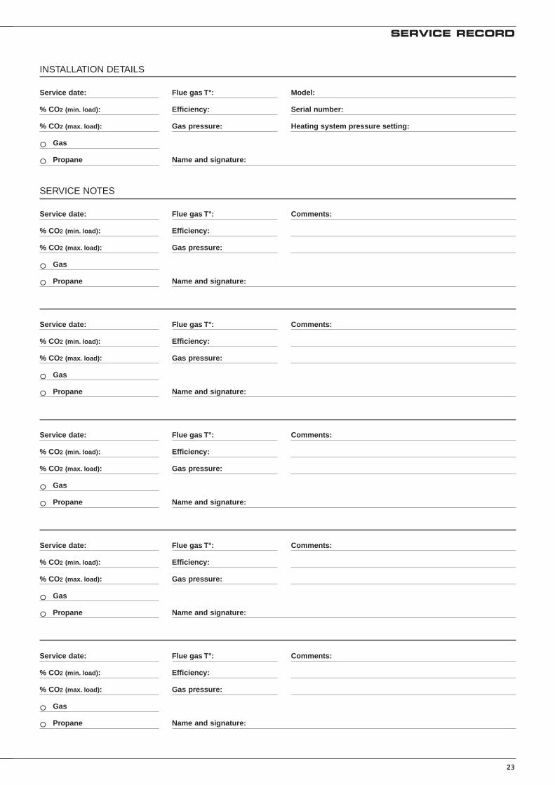
SERVICE RECORD
Service date:
% CO2 (min. load):
% CO2 (max. load):
Gas
Propane
Model:
Serial number:
Heating system pressure setting:
o
o Name and signature:
Flue gas T°:
Efficiency:
Gas pressure:
INSTALLATION DETAILS
Service date:
% CO2 (min. load):
% CO2 (max. load):
Gas
Propane
Comments:
o
o Name and signature:
Flue gas T°:
Efficiency:
Gas pressure:
SERVICE NOTES
Service date:
% CO2 (min. load):
% CO2 (max. load):
Gas
Propane
Comments:
o
o Name and signature:
Flue gas T°:
Efficiency:
Gas pressure:
Service date:
% CO2 (min. load):
% CO2 (max. load):
Gas
Propane
Comments:
o
o Name and signature:
Flue gas T°:
Efficiency:
Gas pressure:
Service date:
% CO2 (min. load):
% CO2 (max. load):
Gas
Propane
Comments:
o
o Name and signature:
Flue gas T°:
Efficiency:
Gas pressure:
Service date:
% CO2 (min. load):
% CO2 (max. load):
Gas
Propane
Comments:
o
o Name and signature:
Flue gas T°:
Efficiency:
Gas pressure:

24
SERVICE RECORD
Service date:
% CO2 (min. load):
% CO2 (max. load):
Gas
Propane
Comments:
o
o Name and signature:
Flue gas T°:
Efficiency:
Gas pressure:
Service date:
% CO2 (min. load):
% CO2 (max. load):
Gas
Propane
Comments:
o
o Name and signature:
Flue gas T°:
Efficiency:
Gas pressure:
Service date:
% CO2 (min. load):
% CO2 (max. load):
Gas
Propane
Comments:
o
o Name and signature:
Flue gas T°:
Efficiency:
Gas pressure:
Service date:
% CO2 (min. load):
% CO2 (max. load):
Gas
Propane
Comments:
o
o Name and signature:
Flue gas T°:
Efficiency:
Gas pressure:
Service date:
% CO2 (min. load):
% CO2 (max. load):
Gas
Propane
Comments:
o
o Name and signature:
Flue gas T°:
Efficiency:
Gas pressure:
Service date:
% CO2 (min. load):
% CO2 (max. load):
Gas
Propane
Comments:
o
o Name and signature:
Flue gas T°:
Efficiency:
Gas pressure:


INTERNATIONALACV international n.vKERKPLEIN, 39B-1601 RUISBROEK - BELGIUMTEL.: +32 2 334 82 20FAX: +32 2 378 16 49E-MAIL: [email protected]
BELGIUMACV BELGIUM nv/saKERKPLEIN, 39B-1601 RUISBROEK-BELGIUMTEL.: +32 2 334 82 40FAX: +32 2 334 82 59E-MAIL: [email protected]
CHILEALBIN TROTTER Y ACV LTDASAN PABLO 3800QUINTA NORMAL - SANTIAGO - CHILETEL.:+56 2 772 01 69FAX:+56 2 772 92 62/63E-MAIL: [email protected]
CZECH REPUBLICACV CR SPOL. s.r.oNA KRECKU 365CR-109 04 PRAHA 10 - CZECH REPUBLICTEL.:+420 2 720 83 341FAX:+420 2 720 83 343E-MAIL: [email protected]
DEUTSCHLANDACV WÄRMETECHNIK GMBH & CO KGGEWERBEGEBIET GARTENSTRASSED-08132 MÜLSEN OT ST. JACOB - DEUTSCHLANDTEL.:+49 37601 311 30FAX:+49 37601 311 31E-MAIL: [email protected]
ESPAÑAACV ESPAÑAC/DE LA TEIXIDORA, 76POL. IND. LES HORTESE-08302 MATARÓ - ESPANATEL.:+34 93 759 54 51FAX:+34 93 759 34 98E-MAIL: [email protected]
FRANCEACV FRANCE sa31, RUE AMPERE - Z.I MI - PLAINEF-69680 CHASSIEU - FRANCETEL.:+33 4 72 47 07 76FAX:+33 4 72 47 08 72E-MAIL: [email protected]
ITALIAACV ITALIAVIA PANA 92I-48018 FAENZA (RA) - ITALIATEL.:+39 0546 64 61 44FAX:+39 0546 64 61 50E-MAIL: [email protected]
NEDERLANDACV NEDERLAND bvPOSTBUS 350NL-2980 AJ RIDDERKERK - NEDERLANDTEL.:+31 180 42 10 55FAX:+31 180 41 58 02E-MAIL: [email protected]
POLANDACV POLSKA sp. z.o.o.UL.WITOSA 3 87 - 800 WLOCLAWEK - POLANDTEL.:+48 54 412 56 00FAX:+48 54 412 56 01E-MAIL: [email protected]
PORTUGALBOILERNOX LDARUA OUTEIRO DO POMARCASAL DO CEGO, FRACÇÃO C,PAVILHÃO 3 - MARRAZES2400-402 LEIRIA - PORTUGALTEL.:+351 244 837 239/40FAX:+351 244 823 758E-MAIL: [email protected]
RUSSIAACV RUSSIA1/9, MALYI KISELNYI103031 MOSCOW - RUSSIATEL.:+7 095 928 48 02 / +7 095 921 89 79FAX:+7 095 928 08 77E-MAIL: [email protected]
SLOVAK REPUBLICACV SLOVAKIA s.r.o.PLUHOVÁ 49831 04 BRATISLAVA - SLOVAK REPUBLICTEL.:+421 2 444 62 276FAX:+421 2 444 62 275E-MAIL: [email protected]
SLOVENIAACV D.O.O. SLOVENIAOPEKARNA 22b1420 TRBOVLJE - SLOVENIATEL.:+386 356 32 830FAX:+ 386 356 32 831E-MAIL: [email protected]
UKACV UK LtdST. DAVID’S BUSINESS PARKDALGETY BAY - FIFE - KY11 9PFTEL.:+44 1383 82 01 00FAX:+44 1383 82 01 80E-MAIL: [email protected]
USATRIANGLE TUBE PHASE IIIFREEWAY CENTER - 1 TRIANGLE LANEBLACKWOOD NJ 08012 - USATEL.:+1 856 228 8881FAX:+1 856 228 3584E-MAIL: [email protected]
excellence in hot water
ww
w.a
cv-w
orl
d.c
om
ARGENTINATECNOPRACTICAALFEREZ BOUCHARD 48571605 CARAPACHAY - BUENOS AIRESTEL.: +54 11 47 65 33 35FAX: +54 11 47 65 43 07E-MAIL: [email protected]
AUSTRALIAHUNT HEATING PTY LTD10 GARDEN BOULEVARD3172 VICTORIA - AUSTRALIATEL.: +61 3 9558 7077FAX: +61 3 9558 7027E-MAIL: [email protected]
BRAZILSIMETAL INDUSTRIA E COMERCIODE FERRAMENTAS LTDARUA GERSON ANDREIS 53595112 - 130 CAXIAS DO SUL - BRAZILTEL.: +55 54 227 12 44FAX: +55 54 227 12 26E-MAIL: [email protected]
BULGARIAPROXIMUS ENGINEERING LTD7 BIAL KREM STR.9010 VARNA - BULGARIATEL.:+359 52 500 070FAX:+359 52 301 131E-MAIL: [email protected]
CHINABEIJING HUADIAN HT POWER TECHNOLOGYDEVELOPMENT CO. LTDROOM B-912, TOWER B, COFCO PLAZAN°. 8, JIANGUOMENNEI AVENUEBEIJING 100005 - PEOPLE’S REPUBLIC OF CHINATEL.:+86 10 652 30 363/393 EXT 101FAX:+86 10 652 27 071E-MAIL: [email protected]
SHANGHAI COOLTECH LTD14/F E. CHINA MERCHANTS PLAZAN°. 333 CHENGDU ROAD (N)200041 SHANGHAI - CHINATEL.:+86 21 52 98 11 22 - 820FAX:+86 21 52 98 13 58E-MAIL: [email protected]
DENMARKVARMEHUSETFRICHSVEJ 40 A8600 SILKEBORG - DENMARKTEL.:+45 86 82 63 55FAX:+45 86 82 65 03E-MAIL: [email protected]
ESTONIATERMOX ASTAHE 112A51013 TARTU - ESTONIATEL.:+372 736 73 39FAX:+372 736 73 44E-MAIL: [email protected]
GREECEESTIASMARASLI STREET 754248 THESSALONIKI - GREECETEL.:+30 23 10 31 98 77 / +30 23 10 32 03 58FAX:+30 23 10 31 97 22E-MAIL: [email protected]
ÎLE MAURICESOTRATECH29, RUE MELDRUMBEAU BASSIN - ÎLE MAURICETEL.:+230 46 76 970FAX:+230 46 76 971E-MAIL: [email protected]
LITHUANIAUAB “GILIUS IR KO”SAVARNORIU PR. 1923000 KAUNAS - LITHUANIATEL.:+370 37 308 930FAX:+370 37 308 932
MAROCCASATHERMPLACE EL YASSIR20300 CASABLANCA - MAROCTEL.:+212 22 40 15 23FAX:+212 22 24 04 86
NEW ZEALANDENERGY PRODUCTS INTERNATIONAL8/10 BELFAST PLACEPO BOX 15058 HAMILTON - NEW ZEALANDTEL.:+64 7 847 27 05FAX:+64 7 847 42 22E-MAIL: [email protected]
ÖSTERREICHPROTHERM HEIZUNGSTECHNIK GmbhTRAUNUFERSTRASSE 1134052 ANSFELDEN - ÖSTERREICHTEL.:+43 7229 804 82FAX:+43 7229 804 92E-MAIL: [email protected]
ROMANIASC TRUST EURO THERM SAD.N PIATRA NEAMT - ROMAN km 2 C.P 5 O.P 3 jud. Neamt5600 PIATRA NEAMT - ROMANIATEL.:+40 233 20 62 06FAX:+40 233 20 62 00E-MAIL: [email protected]
TUNISIESO.CO.ME CHAUMAXBOÎTE POSTALE N°441002 TUNIS - TUNISIETEL.:+216 71 78 15 91FAX:+216 71 78 87 31
UKRAINEUKRTEPLOSERVICE LTDPR. LAGUTENKO 1483086 DONETSK - UKRAINETEL.:+38 062 382 60 47/48FAX:+38 062 335 16 89