Embed Size (px)
Citation preview

INSTALLATION MANUAL IEC & UL Version
THE MODULE TSM-PEG5
TSM-PEG5.07
TSM-PEG40.07
TSM-PEG14
TSM-PEG14(II)
TSM-DEG5(II)
TSM-DEG5.07(II)
TSM-DEG40.07(II)
TSM-DEG14(II)
Date: Feb, 2016 DOC: PS-M-0024 B Page - 2 - of 14
Table of Contents
1. DISCLAIMER OF LIABILITY ............................................................................................................................. - 3 -
2. SAFETY PRECAUTIONS ..................................................................................................................................... - 3 -
3. UNPACKING AND STORAGE ............................................................................................................................ - 3 -
4. PRODUCT IDENTIFICATION ............................................................................................................................ - 4 -
5. ENVIRONMENTAL CONDITIONS AND SITE SELECTION ........................................................................... - 4 -
5.1 CLIMATE CONDITION .................................................................................................................................. - 4 - 5.2 SITE SELECTION ........................................................................................................................................... - 4 -
6. MOUNTING INSTRUCTIONS—TRINA CLAMP ........................................................................................... - 4 -
6.1 COMPONENTS OVERVIEW ............................................................................................................................ - 4 - 6.2 MATERIAL BOM.............................................................................................................................................. - 5 - 6.3 MOUNTING METHODS ................................................................................................................................... - 5 - 6.4 TRINA CLAMP COMPATIBILITY WITH VARIOUS RACKING SYSTEMS. .................................................. - 7 - 6.5 CLAMP OPTIONS ............................................................................................................................................. - 9 - 6.5.1 60PCS&40PCS MODULES .............................................................................................................................. - 9 - 6.5.2 72PCS MODULES .......................................................................................................................................... - 9 -
7. MODULE WIRING ............................................................................................................................................ - 10 -
8. MODULE TILT ANGLE .................................................................................................................................... - 10 -
9. MECHANICAL DRAWING OF PV MODULE ................................................................................................ - 11 -
10. MAINTENANCE AND CARE ............................................................................................................................ - 13 -
11. SPECIFICATIONS ............................................................................................................................................. - 13 -
12. BYPASS DIODES AND BLOCKING DIODES ................................................................................................. - 13 -
13. CONTACTS ........................................................................................................................................................ - 14 -
Date: Feb, 2016 DOC: PS-M-0024 B Page - 3 - of 14
1. DISCLAIMER OF LIABILITY
The installation, handling and use of Trina Solar DUOMAX crystalline series modules are beyond company control.
Accordingly, Trina Solar does not assume responsibility for loss, damage, injury or expense resulting from improper
installation, handling, use or maintenance.
Trina Solar assumes no responsibility for any infringement of patents or other rights of third parties that may result from use
of the module. No license is granted by implication or under any patent or patent rights.
Specifications included in this manual are subject to change without prior notice.
2. SAFETY PRECAUTIONS
1. When designing the PV system, please always take into consideration the variation of the voltage under different
temperatures (please check the respective temperature coefficient specifications of the modules, the Voc of the modules
will rise when the temperature drops);
2. Trina Solar requires that every DUOMAX series PV module string should be fused prior to be connected with other
strings. For the maximum fuse rate, please refer to the detailed SPEC in the last page.
3. Solar photovoltaic (PV) modules generate electricity when exposed to light. An array of many such modules can cause
lethal shocks and/or burn hazards. Only authorized and trained personnel should have access to the modules.
4. Use properly insulated tools and appropriate protective equipment to reduce risk of electric shock.
5. Do not stand or step on the module.
6. Do not damage or scratch the front or backside surfaces of the module.
7. Never use a module with broken glass or top substrate. Broken modules should not be repaired and contact with any module surface can lead to electrical shock.
8. Do not disassemble the modules or remove any part of the module.
9. Protect plug contacts against soiling and do not make any plug connections using soiled plug contacts.
10. Do not install or handle modules when they are wet or during periods of high wind.
11. Do not connect cable from the positive terminal to the positive terminal of one single PV module.
12. Make sure connectors have no gap between insulators. A gap can cause fire hazard and/or danger of an electrical shock.
13. Make sure that the polarity of each module or a string is not reversed relative to the other the modules or strings
14. Artificially concentrated sunlight should not be used on the PV module.
15. In markets conforming to IEC standard, maximum system voltage must not exceed 1500V DC. In markets conforming
to UL standard, maximum system voltage must not exceed 1000V DC. For roof use, the maximum system voltage must
not exceed 600V according to National Electrical Code.
16. Under normal conditions, a photovoltaic module is likely to experience conditions that produce more current and/or voltage than reported at standard test conditions. The requirements of the National Electrical Code (NEC) in Article
690 shall be followed to address these increased outputs. In installations not under the requirements of the NEC, the
values of ISC and VOC marked on this module should be multiplied by a factor of 1.25 when determining component
voltage ratings, conductor ampacities, over-current device ratings, and size of controls connected to the PV output.
17. Our module application class is class A, modules rated for use in this application class may be used in systems
operating at greater than 50V DC or 320W, where general contact access is anticipated..
18. Installation shall be in accordance with CSA C22.1, Safety Standard for Electrical Installations, Canadian Electrical
Code, Part 1.
19. A module with exposed conductive parts is considered to be in compliance with UL 1703 only when it is electrically
grounded in accordance with the instructions presented below and the requirements of the National Electrical Code.
20. The DUOMAX modules have achieved fire rating Type 13 according UL1703 updated on 20th May 2014. The fire rating of this module is valid only when mounted as specified in the mechanical mounting instructions in this document.
21. The actual system fire rating should always be evaluated along with the roof cover and mounting.
22. Any module without a frame (laminate) shall not be considered to comply with the requirements of UL 1703 unless the
module is mounted with hardware that has been tested and evaluated with the module under this standard or by a field
Inspection certifying that the installed module complies with the requirements of UL 1703.
3. UNPACKING AND STORAGE
1. Before installation, keep all modules and electrical contacts clean and dry.
2. If it is necessary to store modules temporarily, a dry, ventilated room should be used.
3. When unpacking, carry modules with both hands. Do not place modules on top of each other.
Date: Feb, 2016 DOC: PS-M-0024 B Page - 4 - of 14
4. The double glass module should be handled carefully, so non-slip gloves are required for handling and installation.
5. Please use the appropriate removal tools when dismantling the plywood cases.
4. PRODUCT IDENTIFICATION
We recommend that you take note of the unique serial number on each module.
5. ENVIRONMENTAL CONDITIONS AND SITE SELECTION
5.1 CLIMATE CONDITION
Install Trina Solar Crystalline series modules in the following conditions:
Ambient temperature: -40°C to +50°C
Operating temperature: -40°C to +85°C
Storage temperature: -20°C to +50°C
Humidity: below 85RH%
Mechanical Load Pressure*: 5400Pa (550 Kg/m²) Max from the front side (snow) 2400Pa (wind) from the
rear.
* Mechanical load bearing specifications (including wind and snow loads) of the module is based on Trina Solar mounting
methods. A professional system installer must be responsible for the mechanical load calculations based on the specific system design.
5.2 SITE SELECTION
1. In most applications, Trina Solar PV modules should be installed in a location where they will receive maximum
sunlight throughout the year.
2. Modules should not be shaded by buildings, trees, chimney, etc. at any time of the day.
3. Do not install in corrosive environments, such as beaches or landfill that can be easily flooded.
4. Do not install PV modules in a location where modules could be immersed in water or continually exposed to water
from a sprinkler or fountain.
5. Do not install PV modules over naked flames or flammable materials.
6. Interspaces, the clearance between the module edge and surface of the wall or roof, of at least 115mm is required to prevent wiring damage and to allow air to circulate behind the module.
6. MOUNTING INSTRUCTIONS—TRINA CLAMP
The DUOMAX module is considered to be in compliance with UL 1703 only when the module is mounted in the manner
specified by the mounting instructions below. This mounting is using Trina Clamps, alternate mountings are available.
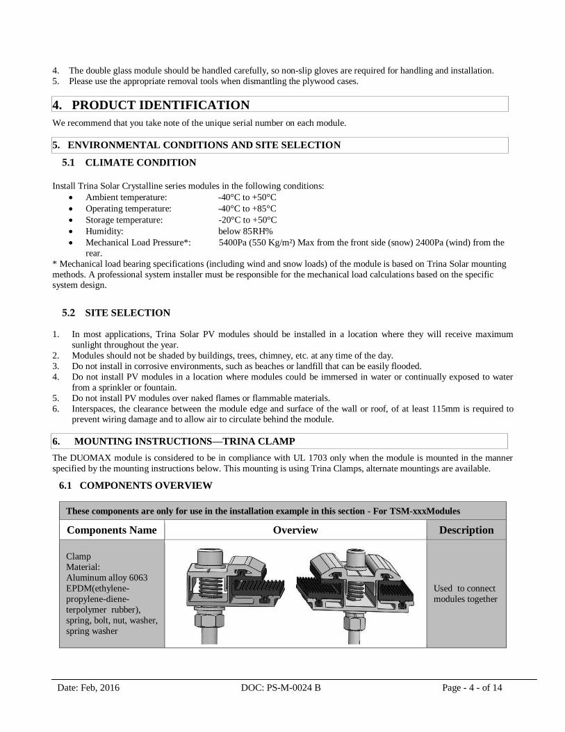
6.1 COMPONENTS OVERVIEW
These components are only for use in the installation example in this section - For TSM-xxxModules
Components Name Overview Description
Clamp
Material:
Aluminum alloy 6063
EPDM(ethylene-
propylene-diene-
terpolymer rubber),
spring, bolt, nut, washer,
spring washer
Used to connect
modules together
Date: Feb, 2016 DOC: PS-M-0024 B Page - 5 - of 14
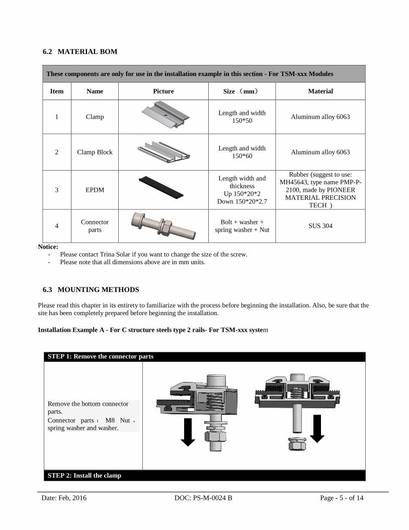
6.2 MATERIAL BOM
These components are only for use in the installation example in this section - For TSM-xxx Modules
Item Name Picture Size (mm) Material
1 Clamp
Length and width
150*50 Aluminum alloy 6063
2 Clamp Block
Length and width
150*60 Aluminum alloy 6063
3 EPDM
Length width and
thickness
Up 150*20*2
Down 150*20*2.7
Rubber (suggest to use:
MH45643, type name PMP-P-
2100, made by PIONEER
MATERIAL PRECISION
TECH )
4 Connector
parts
Bolt + washer +
spring washer + Nut SUS 304
Notice:
- Please contact Trina Solar if you want to change the size of the screw.
- Please note that all dimensions above are in mm units.
6.3 MOUNTING METHODS
Please read this chapter in its entirety to familiarize with the process before beginning the installation. Also, be sure that the
site has been completely prepared before beginning the installation.
Installation Example A - For C structure steels type 2 rails- For TSM-xxx system
STEP 1: Remove the connector parts
Remove the bottom connector
parts.
Connector parts : M8 Nut 、spring washer and washer.
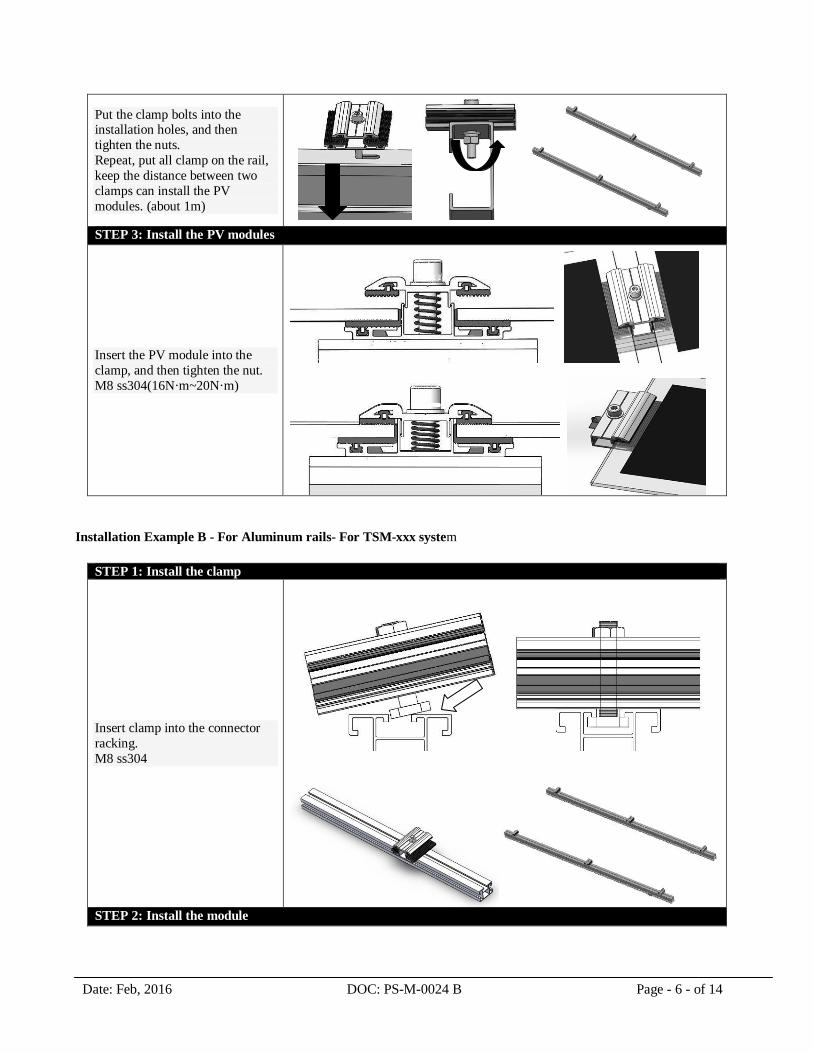
STEP 2: Install the clamp
Date: Feb, 2016 DOC: PS-M-0024 B Page - 6 - of 14
Put the clamp bolts into the installation holes, and then
tighten the nuts.
Repeat, put all clamp on the rail,
keep the distance between two
clamps can install the PV
modules. (about 1m)
STEP 3: Install the PV modules
Insert the PV module into the
clamp, and then tighten the nut.
M8 ss304(16N·m~20N·m)
Installation Example B - For Aluminum rails- For TSM-xxx system
STEP 1: Install the clamp
Insert clamp into the connector
racking.
M8 ss304
STEP 2: Install the module

Date: Feb, 2016 DOC: PS-M-0024 B Page - 7 - of 14
Insert the PV module into the
clamp, and then tighten the nut.
M8 ss304(16N·m~20N·m)
*NOTE: Test the installation of the bolt torque on a regular basis.
6.4 TRINA CLAMP COMPATIBILITY WITH VARIOUS RACKING SYSTEMS.
The following examples illustrate how to evaluate Trina Clamp compatibility with various racking systems. Please find the dimension below to evaluate the racking system, contact Trina Solar if you want to change the size of the
screw. Please note that all dimensions below are in mm units.
Section view of the installation
1. Clamp
2. EPDM 3. Clamp Block
27
Date: Feb, 2016 DOC: PS-M-0024 B Page - 8 - of 14
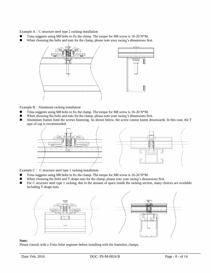
Example A:C structure steel type 2 racking installation
Trina suggests using M8 bolts to fix the clamp. The torque for M8 screw is 16-20 N*M.
When choosing the bolts and nuts for the clamp, please note your racing’s dimensions first.
Example B:Aluminum racking installation
Trina suggests using M8 bolts to fix the clamp. The torque for M8 screw is 16-20 N*M. When choosing the bolts and nuts for the clamp, please note your racing’s dimensions first.
Aluminum frames limit the screws fastening. As shown below, the screw cannot fasten downwards. In this case, the T
type of cap is recommended.
Example C: C structure steel type 1 racking installation
Trina suggests using M8 bolts to fix the clamp. The torque for M8 screw is 16-20 N*M.
When choosing the bolts and T-shape nuts for the clamp, please note your racing’s dimensions first.
For C structure steel type 1 racking, due to the amount of space inside the racking section, many choices are available
including T-shape nuts.
Note:
Please consult with a Trina Solar engineer before installing with the frameless clamps.
Date: Feb, 2016 DOC: PS-M-0024 B Page - 9 - of 14
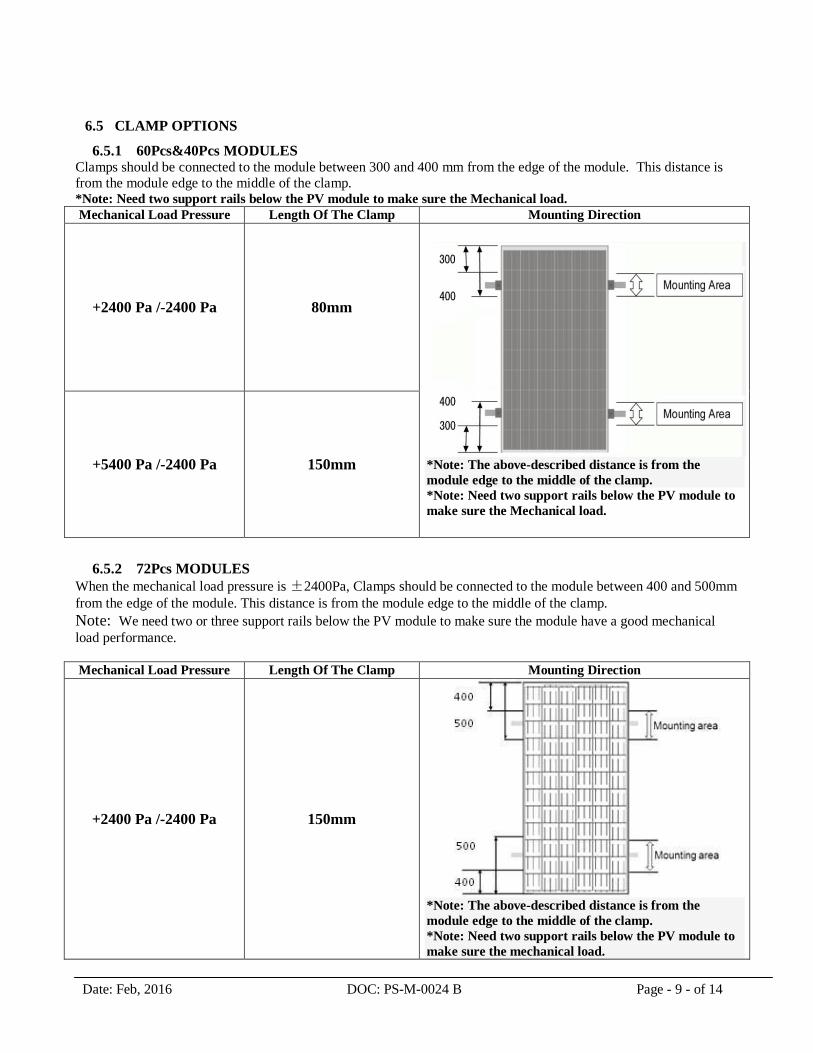
6.5 CLAMP OPTIONS
6.5.1 60Pcs&40Pcs MODULES Clamps should be connected to the module between 300 and 400 mm from the edge of the module. This distance is
from the module edge to the middle of the clamp. *Note: Need two support rails below the PV module to make sure the Mechanical load. Mechanical Load Pressure Length Of The Clamp Mounting Direction
+2400 Pa /-2400 Pa 80mm
*Note: The above-described distance is from the
module edge to the middle of the clamp.
*Note: Need two support rails below the PV module to
make sure the Mechanical load.
+5400 Pa /-2400 Pa 150mm
6.5.2 72Pcs MODULES
When the mechanical load pressure is ±2400Pa, Clamps should be connected to the module between 400 and 500mm
from the edge of the module. This distance is from the module edge to the middle of the clamp. Note: We need two or three support rails below the PV module to make sure the module have a good mechanical
load performance.
Mechanical Load Pressure Length Of The Clamp Mounting Direction
+2400 Pa /-2400 Pa 150mm
*Note: The above-described distance is from the
module edge to the middle of the clamp.
*Note: Need two support rails below the PV module to
make sure the mechanical load.

Date: Feb, 2016 DOC: PS-M-0024 B Page - 10 - of 14
+5400 Pa /-2400 Pa 150mm
*Note:+5400 Pa when using 3 row connectors to
support the module, the distance is from the module
edge to the middle of the clamp.
*Note: Need three support rails below the PV module
to make sure the mechanical load.
7. MODULE WIRING
Each module has two 4mm2 diameter type standard 90°C sunlight resistant output cables each terminated with plug & play
connectors. This cable is suitable for applications where wiring is exposed to the direct rays of the sun. We recommend that all wiring and electrical connections comply with the appropriate national electrical code(s).
For field connections, use the minimum 4mm2 diameter copper wires insulated for a minimum of 90°C and sunlight
resistant as well.
The minimum and maximum outer diameters of the cable are 5mm to 7mm. Refer to Datasheet Specifications for the
maximum electrical rating of series fuse.
8. MODULE TILT ANGLE
Trina Solar PV modules connected in series should be installed at the same orientation and angle. Different orientation or
angle may cause loss of output power because each module may be exposed to different amounts of solar irradiation.
Trina Solar PV modules produce the most power when they are perpendicular to incoming sunlight. For installations where
the PV modules are attached to a permanent structure, the PV modules should be tilted for optimum winter performance.
The module tilt angle is measured between the solar modules and the ground. Optimal tilting of PV module is almost the
same as the latitude of installation location.
SPV module Tilt angle
Date: Feb, 2016 DOC: PS-M-0024 B Page - 11 - of 14
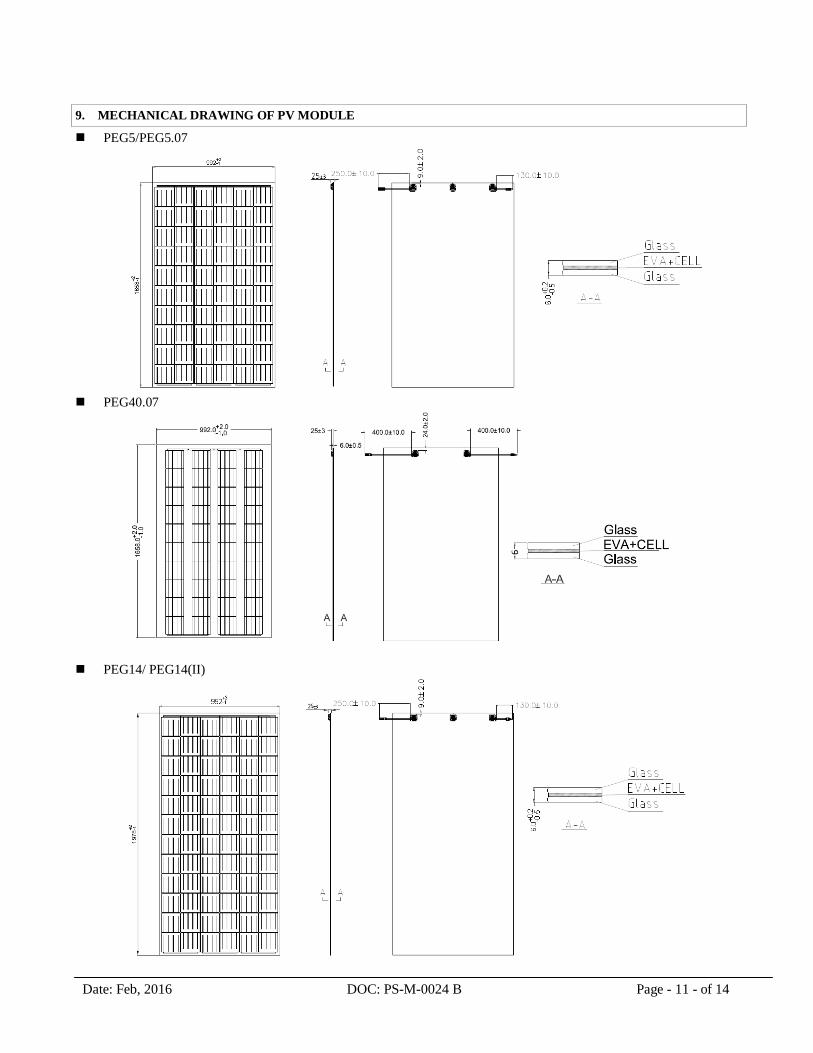
9. MECHANICAL DRAWING OF PV MODULE
PEG5/PEG5.07
PEG40.07
PEG14/ PEG14(II)
Date: Feb, 2016 DOC: PS-M-0024 B Page - 12 - of 14
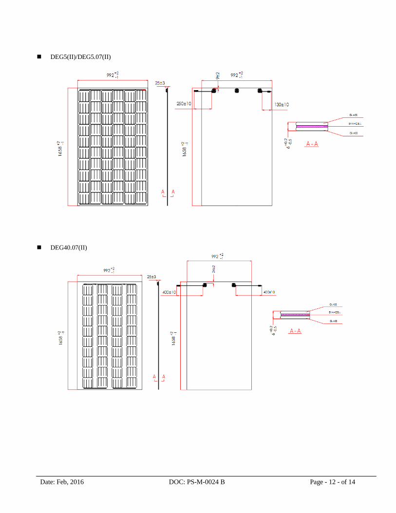
DEG5(II)/DEG5.07(II)
DEG40.07(II)
Date: Feb, 2016 DOC: PS-M-0024 B Page - 13 - of 14
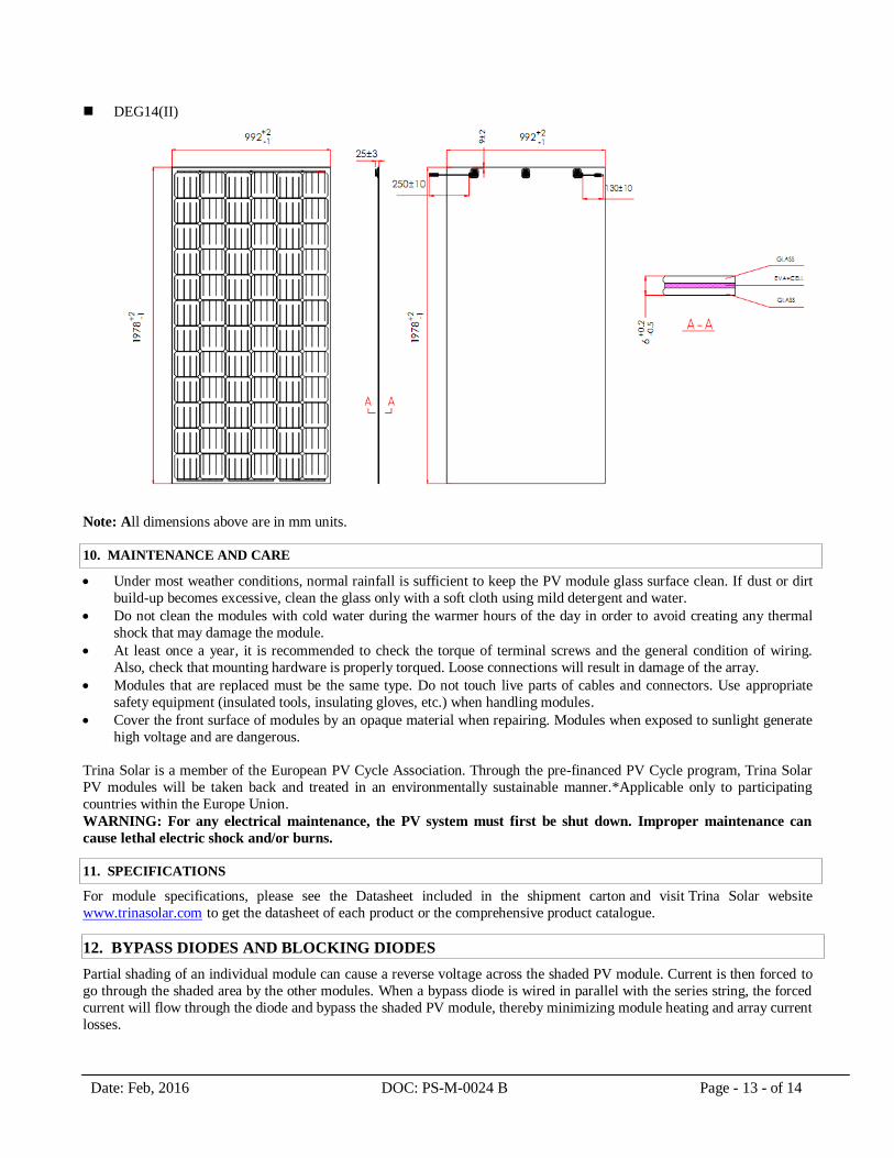
DEG14(II)
Note: All dimensions above are in mm units.
10. MAINTENANCE AND CARE
Under most weather conditions, normal rainfall is sufficient to keep the PV module glass surface clean. If dust or dirt
build-up becomes excessive, clean the glass only with a soft cloth using mild detergent and water.
Do not clean the modules with cold water during the warmer hours of the day in order to avoid creating any thermal
shock that may damage the module.
At least once a year, it is recommended to check the torque of terminal screws and the general condition of wiring.
Also, check that mounting hardware is properly torqued. Loose connections will result in damage of the array.
Modules that are replaced must be the same type. Do not touch live parts of cables and connectors. Use appropriate
safety equipment (insulated tools, insulating gloves, etc.) when handling modules.
Cover the front surface of modules by an opaque material when repairing. Modules when exposed to sunlight generate
high voltage and are dangerous.
Trina Solar is a member of the European PV Cycle Association. Through the pre-financed PV Cycle program, Trina Solar
PV modules will be taken back and treated in an environmentally sustainable manner.*Applicable only to participating
countries within the Europe Union.
WARNING: For any electrical maintenance, the PV system must first be shut down. Improper maintenance can
cause lethal electric shock and/or burns.
11. SPECIFICATIONS
For module specifications, please see the Datasheet included in the shipment carton and visit Trina Solar website
www.trinasolar.com to get the datasheet of each product or the comprehensive product catalogue.
12. BYPASS DIODES AND BLOCKING DIODES
Partial shading of an individual module can cause a reverse voltage across the shaded PV module. Current is then forced to
go through the shaded area by the other modules. When a bypass diode is wired in parallel with the series string, the forced
current will flow through the diode and bypass the shaded PV module, thereby minimizing module heating and array current
losses.
Date: Feb, 2016 DOC: PS-M-0024 B Page - 14 - of 14
Currently, Trina Solar PV modules are equipped with bypass diodes in the junction box. The diode type is SB3040DY,
(rated maximum 40V PIV, 16A, 3pcs provided). Do not try to open the junction box to change the diodes even if it
malfunctions.
In a system that uses a battery, blocking diodes are typically placed between the battery and the PV module output to
prevent battery discharge at night.
Diodes that are used as blocking diodes must have:
− Rated Average Forward Current [IF(AV)] above the maximum system current at the highest module operating
temperature.
− Rated Repetitive Peak Reverse Voltage [VRRM] above the maximum system voltage at the lowest module operating temperature.
13. CONTACTS
These solar modules do not contain any user serviceable parts.
If you suspect that your installation is not working properly, then contact your installer immediately.
1. Contact your installer
2. Contact Trina Solar after-sales service team at: http://customerservice.trinasolar.com
3. Submit the Customer Feedback form at: www.trinasolar.com; one of our technical service representatives
will contact you as quickly as possible. A username and password is required to send feedback from the
customer service link
WARNING: For any electrical maintenance, the PV system must first be shut down. Improper maintenance
can cause lethal electric shock and/or burns.