Embed Size (px)
Citation preview
INST
ALLA
TION
MAN
UAL
INST
ALLA
TION
MAN
UAL
MANUEL D’INSTALLATION
AVH-P4000DVD
<KSNNX> <07K00000>
Printed in Thailand Imprimé en Thaïlande
<CRD4281-A/N> UC
Connecting the units
WARNING
• To avoid the risk of accident and the potential violation of applicable laws, the front DVD or TV (sold separately) feature should never be used while the vehicle is being driven. Also, Rear Displays should not be in a location where it is a visible distraction to the driver.
• In some countries or states the viewing of images on a display inside a vehicle even by persons other than the driver may be illegal. Where such regulations apply, they must be obeyed and this unit’s DVD features should not be used.
CAUTION
• PIONEER does not recommend that you install or service your display yourself. Installing or servicing the product may expose you to risk of electric shock or other hazards. Refer all installation and servicing of your display to authorized Pioneer service personnel.
• Secure all wiring with cable clamps or electrical tape. Do not allow any bare wiring to remain exposed.
• Do not drill a hole into the engine compartment to connect the yellow lead of the unit to the vehicle battery. Engine vibration may eventually cause the insulation to fail at the point where the wire passes from the passenger compartment into the engine compartment. Take extra care in securing the wire at this point.
• It is extremely dangerous to allow the display lead to become wound around the steering column or gearshift. Be sure to install the display in such a way that it will not obstruct driving.
• Make sure that wires will not interfere with moving parts of the vehicle, such as the gearshift, parking brake or seat sliding mechanism.
• Do not shorten any leads. If you do, the protection circuit may fail to work properly.
WARNING
LIGHT GREEN LEAD AT POWER CONNECTOR IS DESIGNED TO DETECT PARKED STATUS AND MUST BE CONNECTED TO THE POWER SUPPLY SIDE OF THE PARKING BRAKE SWITCH. IMPROPER CONNECTION OR USE OF THIS LEAD MAY VIOLATE APPLICABLE LAW AND MAY RESULT IN SERIOUS INJURY OR DAMAGE.
Note
• This unit cannot be installed in a vehicle without ACC (accessory) position on the ignition switch.
ACCON
STA
R
T
OFF
ONS
TA
R
T
OFF
ACC position No ACC position
• Use this unit in other than the following conditions could result in fire or malfunction.— Vehicles with a 12-volt battery and negative
grounding.— Speakers with 50 W (output value) and 4 ohm
to 8 ohm (impedance value).• To prevent short-circuit, overheating or
malfunction, be sure to follow the directions below.— Disconnect the negative terminal of the
battery before installation.— Secure the wiring with cable clamps or
adhesive tape. To protect the wiring, wrap adhesive tape around them where they lie against metal parts.
— Place all cables away from moving parts, such as gear shift and seat rails.
— Place all cables away from hot places, such as near the heater outlet.
— Do not pass the yellow cable through a hole into the engine compartment to connect to a battery.
— Cover any disconnected cable connectors with insulating tape.
— Do not shorten any cables.— Never cut the insulation of the power cable of
this unit in order to share the power to other equipment. Current capacity of the cable is limited.
— Use a fuse of the rating prescribed.— Never wire the speaker negative cable directly
to ground.— Never band together multiple speaker’s
negative cables.
Connecting the units
• Control signal is output through blue/white cable when this unit is powered on. Connect it to an external power amp’s system remote control or the vehicle’s auto-antenna relay control terminal (max. 300 mA, 12 V DC). If the vehicle is equipped with a glass antenna, connect it to the antenna booster power supply terminal.
• Never connect blue/white cable to external power amp’s power terminal. Also, never connect it to the power terminal of the auto antenna. Otherwise, battery drain or malfunction may result.
• IP-BUS connectors are color-coded. Be sure to connect connectors of the same color.
• Black cable is ground. This cable and other product’s ground cable (especially, high-current products such as power amp) must be wired separately. Otherwise, fire or malfunction may result if they are accidentally detached.
Connecting the units
Parts supplied
This product Power cord USB cable
Frame Flush surface screw(5 × 6 mm) (8 pcs.)
Binding screw(5 × 6 mm) (8 pcs.)
Touch panel pen
Connecting the units
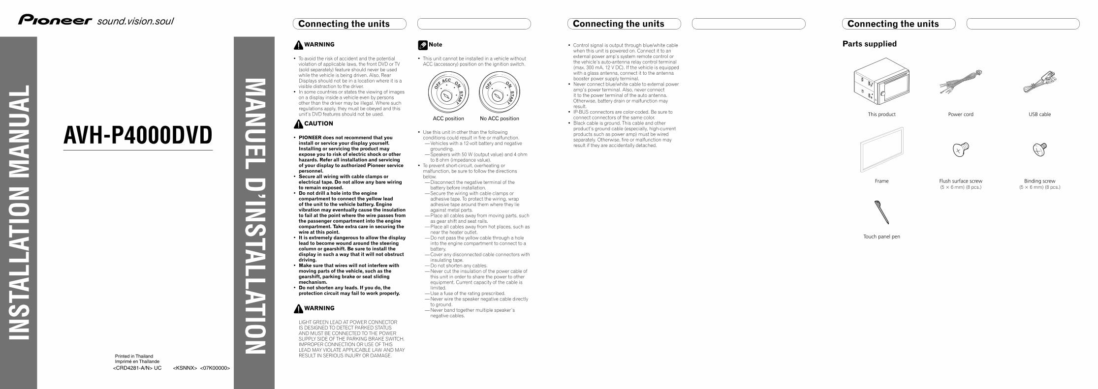
Connecting the power cord
Connection method
1. Clamp the lead. 2. Clamp firmly with needle-nosed pliers.
Note: · The position of the parking brake switch depends on the vehicle model. For details,
consult the vehicle Owner’s Manual or dealer.
Yellow/blackIf you use equipment with Mute function, wire this lead to the Audio Mute lead on that piece of equipment. If not, keep the Audio Mute lead free of any connections.
Light greenUsed to detect the ON/OFF status of the parking brake. This lead must be connected to the power supply side of the parking brake switch.
Blue/whiteConnect to system control terminal of the power amp or auto-antenna relay control terminal (max. 300 mA 12 V DC).
Ground side
Power supply sideParking brake switch
When you connect the separately sold multi-channel processor (e.g., DEQ-P8000) to this unit, do not connect anything to the speaker leads and system remote control (blue/white).
Yellow Connect to the constant 12 V supply terminal.
Fuse resistorRed Connect to terminal controlled by ignition switch (12 V DC).
Black (chassis ground) Connect to a clean, paint-free metal location.
Fuse resistorOrange/white Connect to lighting switch terminal.
Left Right
Front speaker Front speaker
Rear speaker or Subwoofer (4 Ω)
White Gray
Gray/blackWhite/black
Green Violet
Green/black Violet/black
With a 2 speaker system, do not connect anything to the speaker leads that are not connected to speakers.
Note:· Change the initial setting of this unit (refer to the
Operation Manual). The subwoofer output of this unit is monaural.
Violet
Violet/black
Not used.
Green
Green/black
When using a subwoofer of 70 W (2 Ω), be sure to connect with Violet and Violet/black leads of this unit. Do not connect anything to Green and Green/black leads.
Subwoofer (4 Ω) × 2
Rear speaker or Subwoofer (4 Ω)
Fuse (10 A)
This product
Antenna input
Connecting the units Connecting the units
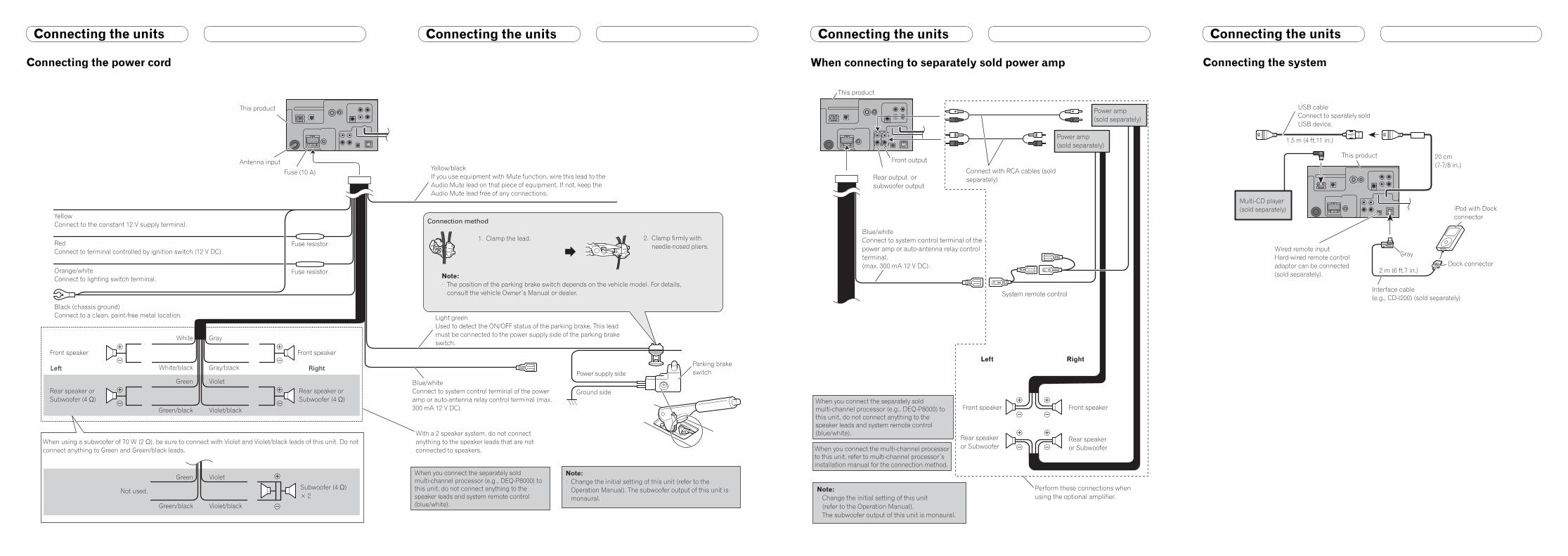
When connecting to separately sold power amp
Note:· Change the initial setting of this unit
(refer to the Operation Manual). The subwoofer output of this unit is monaural.
Blue/whiteConnect to system control terminal of the power amp or auto-antenna relay control terminal.(max. 300 mA 12 V DC).
When you connect the separately sold multi-channel processor (e.g., DEQ-P8000) to this unit, do not connect anything to the speaker leads and system remote control (blue/white).
This product
Connect with RCA cables (sold separately)
Rear speakeror Subwoofer
Perform these connections when using the optional amplifier.
System remote control
Front speaker Front speaker
Left Right
Front output
When you connect the multi-channel processor to this unit, refer to multi-channel processor’s installation manual for the connection method.
Rear speakeror Subwoofer
Power amp (sold separately)
Power amp (sold separately)
Rear output or subwoofer output
Connecting the units
Connecting the system
iPod with Dock connector
Dock connector
Interface cable (e.g., CD-I200) (sold separately)
Gray
This product
1.5 m (4 ft.11 in.)
20 cm(7-7/8 in.)
USB cableConnect to sparately sold USB device.
Wired remote inputHard-wired remote controladaptor can be connected(sold separately).
Multi-CD player (sold separately)
2 m (6 ft.7 in.)
Connecting the units
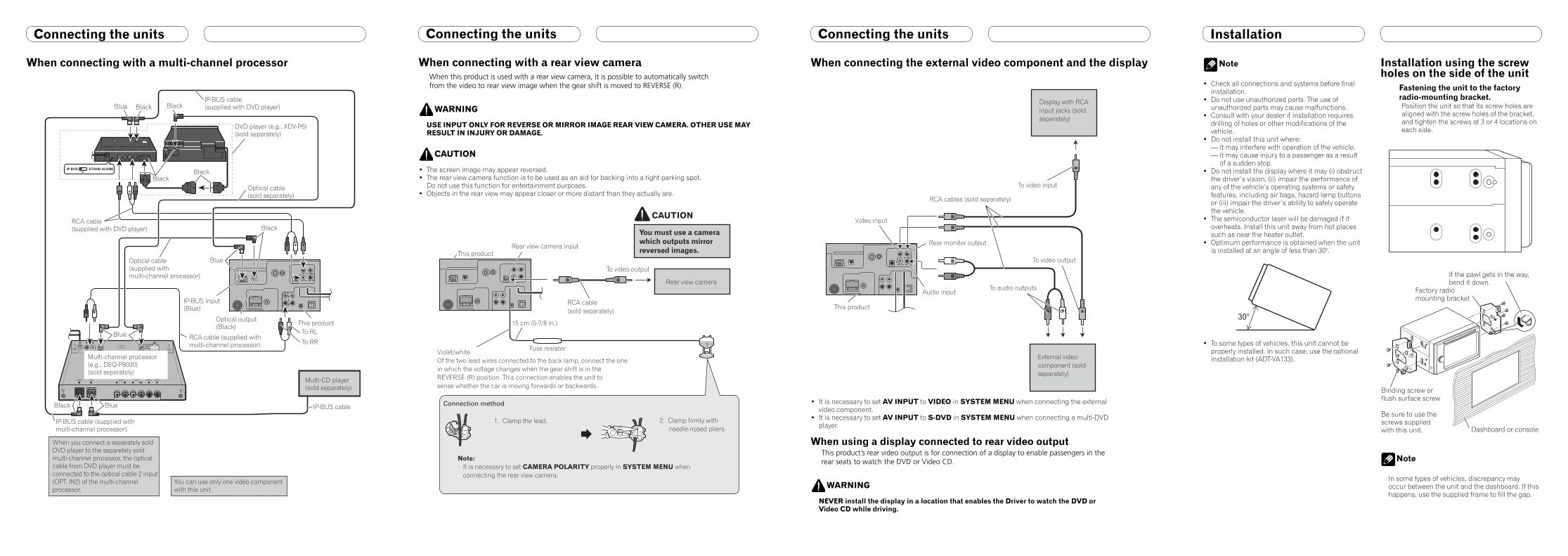
When connecting with a rear view cameraWhen this product is used with a rear view camera, it is possible to automatically switch from the video to rear view image when the gear shift is moved to REVERSE (R).
WARNING
USE INPUT ONLY FOR REVERSE OR MIRROR IMAGE REAR VIEW CAMERA. OTHER USE MAY RESULT IN INJURY OR DAMAGE.
CAUTION
• The screen image may appear reversed.• The rear view camera function is to be used as an aid for backing into a tight parking spot.
Do not use this function for entertainment purposes.• Objects in the rear view may appear closer or more distant than they actually are.
You must use a camera which outputs mirror reversed images.
CAUTION
RCA cable (sold separately)
To video output
Rear view camera
Rear view camera input This product
Violet/whiteOf the two lead wires connected to the back lamp, connect the one in which the voltage changes when the gear shift is in the REVERSE (R) position. This connection enables the unit tosense whether the car is moving forwards or backwards.
15 cm (5-7/8 in.)
Fuse resistor
Connection method
1. Clamp the lead. 2. Clamp firmly with needle-nosed pliers.
Note: · It is necessary to set CAMERA POLARITY properly in SYSTEM MENU when
connecting the rear view camera.
Connecting the units
When connecting with a multi-channel processor
Multi-channel processor(e.g., DEQ-P8000)(sold separately)
BlackBlack
When you connect a separately sold DVD player to the separetely sold multi-channel processor, the optical cable from DVD player must be connected to the optical cable 2 input (OPT. IN2) of the multi-channel processor.
DVD player (e.g., XDV-P6) (sold separately)
Optical output (Black) This product
IP-BUS cable (supplied with multi-channel processor)
Black Blue
Blue
IP-BUS cable (supplied with DVD player)
Optical cable (sold separately)
RCA cable (supplied with multi-channel processor)
RCA cable (supplied with DVD player)
Optical cable (supplied with multi-channel processor)
Blue
IP-BUS input (Blue)
Black
Multi-CD player (sold separately)
IP-BUS cable
BlackBlackBlue
You can use only one video component with this unit.
To RL
To RR
Connecting the units
When connecting the external video component and the display
External video component (sold separately)
Audio input
Display with RCA input jacks (sold separately)
To video input
To video output
To audio outputs
Video input
This product
Rear monitor output
RCA cables (sold separately)
• It is necessary to set AV INPUT to VIDEO in SYSTEM MENU when connecting the external video component.
• It is necessary to set AV INPUT to S-DVD in SYSTEM MENU when connecting a multi-DVD player.
When using a display connected to rear video outputThis product’s rear video output is for connection of a display to enable passengers in the rear seats to watch the DVD or Video CD.
WARNING
NEVER install the display in a location that enables the Driver to watch the DVD or Video CD while driving.
Installation
Note
• Check all connections and systems before final installation.
• Do not use unauthorized parts. The use of unauthorized parts may cause malfunctions.
• Consult with your dealer if installation requires drilling of holes or other modifications of the vehicle.
• Do not install this unit where:— it may interfere with operation of the vehicle.— it may cause injury to a passenger as a result
of a sudden stop.• Do not install the display where it may (i) obstruct
the driver’s vision, (ii) impair the performance of any of the vehicle’s operating systems or safety features, including air bags, hazard lamp buttons or (iii) impair the driver’s ability to safely operate the vehicle.
• The semiconductor laser will be damaged if it overheats. Install this unit away from hot places such as near the heater outlet.
• Optimum performance is obtained when the unit is installed at an angle of less than 30°.
• To some types of vehicles, this unit cannot be properly installed. In such case, use the optional installation kit (ADT-VA133).
Installation using the screw holes on the side of the unit
Fastening the unit to the factory radio-mounting bracket.Position the unit so that its screw holes are aligned with the screw holes of the bracket, and tighten the screws at 3 or 4 locations on each side.
Note
In some types of vehicles, discrepancy may occur between the unit and the dashboard. If this happens, use the supplied frame to fill the gap.
Factory radio mounting bracket
If the pawl gets in the way, bend it down.
Dashboard or console
Binding screw or flush surface screw
Be sure to use the screws supplied with this unit.
Raccordements des appareils
AVERTISSEMENT
• Pour éviter tout risque d’accident, et toute infraction aux lois en vigueur, l’affichage à l’avant d’image de DVD ou de télévision (vendue séparément) ne doit jamais être employé tandis que le véhicule roule. Par ailleurs, les écrans arrière ne doivent jamais se trouver placés de manière à distraire l’attention du conducteur.
• Dans certains états ou pays il peut être illégal même pour des personnes autres que le conducteur de regarder des images sur un écran à l’intérieur d’un véhicule. Quand cette réglementation est applicable, elle doit être respectée, et les fonctions DVD de cet appareil ne doivent pas être utilisées.
ATTENTION
• PIONEER ne vous recommande pas d’installer ou d’entretenir vous-même cet écran, car ces travaux peuvent présenter un risque d’électrocution ou d’autres dangers. Confiez tous les travaux d’installation et d’entretien de votre écran au personnel de service Pioneer agréé.
• Immobilisez toutes les câblages avec des serre-fils ou du ruban isolant. Ne laissez aucun conducteur à nu.
• Ne forez pas un orifice vers le compartiment du moteur afin de raccorder le fil jaune de l’appareil sur la batterie du véhicule car les vibrations du moteur pourraient à la longue abîmer l’isolation du fil au point de passage entre l’habitable et le compartiment du moteur. Veillez tout particulièrement à bien immobiliser le fil à ce point.
• Une situation très dangereuse pourrait se présenter si le fil de l’écran devait s’enrouler autour de la colonne de direction ou du levier des vitesses. Veillez à installer l’écran de telle sorte que rien ne fasse obstacle à la conduite.
• Assurez-vous que les câblages ne font pas obstacle aux pièces mobiles du véhicule, telles que le levier des vitesses, le frein à main ou le mécanisme de coulissement des sièges.
• Ne court-circuitez pas les fils car le circuit de protection ne fonctionnerait plus correctement.
AVERTISSEMENT
LE FIL VERT CLAIR SUR LE CONNECTEUR D’ALIMENTATION A POUR BUT DE DETECTER L’ETAT DE STATIONNEMENT DU VEHICULE ET DOIT ETRE CONNECTE AU COTE ALIMENTATION DU COMMUTATEUR DU FREIN A MAIN. UNE CONNEXION OU UNE UTILISATION INCORRECTE DE CE FIL PEUT VIOLER LA LOI APPLICABLE ET PEUT ENTRAINER DES BLESSURES GRAVES OU DES DOMMAGES SERIEUX.
Remarque
• Cet appareil ne peut pas être installé dans un véhicule dont le contacteur d’allumage ne possède pas de position ACC (accessoire).
ACCON
STA
R
T
OFF
ONS
TA
R
TO
FF
Position ACC Pas de Position ACC
• Utiliser cet appareil dans d’autres conditions que les conditions suivantes peut entraîner un incendie ou un mauvais fonctionnement.— Véhicule avec une batterie de 12 volts et une
mise à la masse négative.— Enceintes de 50 W (valeur de sortie) et de 4
ohms à 8 ohms (valeur d’impédance).• Pour éviter tout court-circuit, surchauffe ou
mauvais fonctionnement, assurez-vous de suivre les instructions ci-dessous.— Déconnectez la borne négative de la batterie
avant l’installation.— Fixez solidement les câbles avec des serre-
câbles ou du ruban adhésif. Pour protéger le câblage, entourez-le de ruban adhésif à l’endroit où il est en contact avec des pièces métalliques.
— Tenez tous les câbles à l’écart des parties mobiles, telles que le levier de vitesse et les rails des sièges.
— Tenez tous les câbles à l’écart des endroits chauds, tels que les sorties du chauffage.
— Ne faites pas passer le câble jaune par un trou dans le compartiment du moteur pour le connecter à la batterie.
— Recouvrez tous les câbles non connectés avec du ruban isolant.
— Ne raccourcissez aucun câble.
Raccordements des appareils
— Ne coupez jamais l’isolant du câble d’alimentation de cet appareil afin partager l’alimentation avec un autre appareil. La capacité électrique du câble est limitée.
— Utilisez un fusible de la valeur donnée.— Ne connectez jamais le câble négatif des
enceintes directement à la masse.— N’attachez jamais ensemble plusieurs câbles
négatifs de plusieurs enceintes.• Le signal de commande est sorti par le câble
bleu/blanc quand cet appareil est sous tension. Connectez-le à la télécommande d’un système d’amplification extérieur ou à la prise de commande du contrôle de relais de l’antenne automatique (max. 300 mA, 12 V CC). Si le véhicule est équipée d’une antenne de vitre, connectez-la à la prise d’alimentation de l’amplificateur d’antenne.
• Ne connectez jamais le câble bleu/blanc à la prise d’alimentation d’un amplificateur extérieur. Et ne le connectez pas à la prise d’alimentation de l’antenne automatique. Sinon, la batterie risque de se décharger ou un mauvais fonctionnement peut se produire.
• Les connecteurs IP-BUS sont codés par couleur. Assurez-vous de connecter les connecteurs de même couleur.
• Le câble noir est pour la masse. Ce câble et les câbles de masse des autres produits (en particulier les appareils à haute intensité tels que les amplificateurs) doivent être câblés séparément. Sinon, ils peuvent entraîner un incendie ou un mauvais fonctionnement s’ils se détachent.
Raccordements des appareils
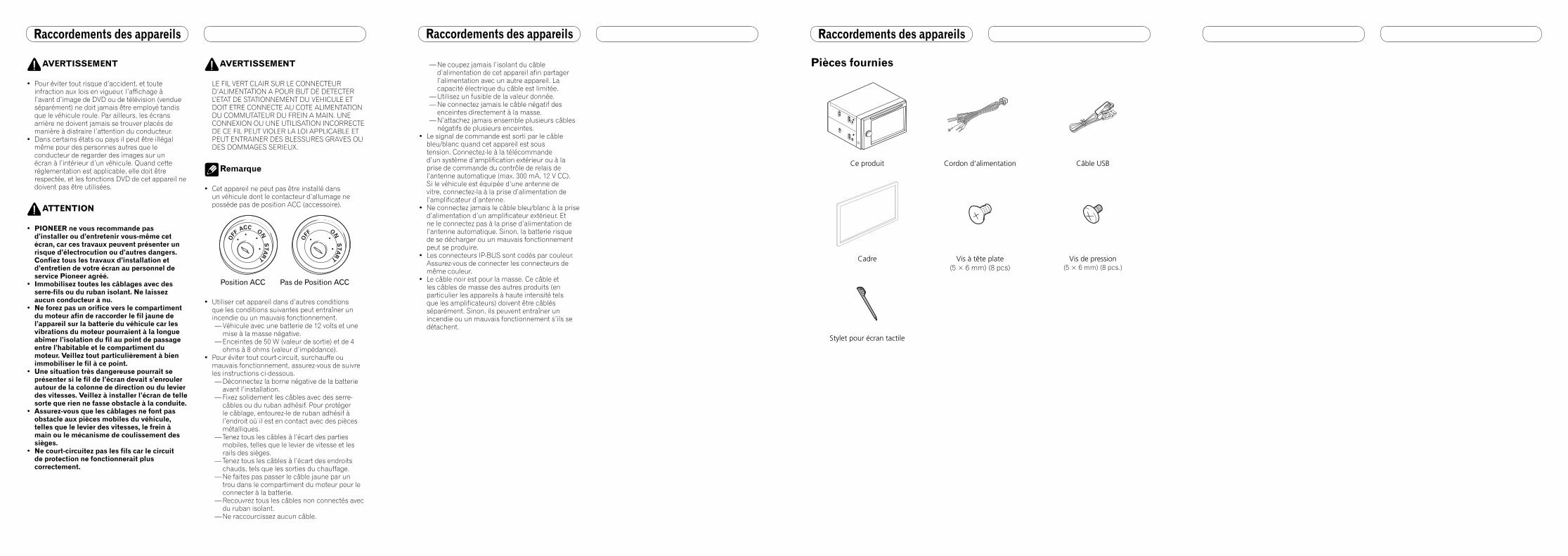
Pièces fournies
Ce produit Cordon d’alimentation Câble USB
Cadre Vis à tête plate (5 × 6 mm) (8 pcs)
Vis de pression(5 × 6 mm) (8 pcs.)
Stylet pour écran tactile
Raccordements des appareils
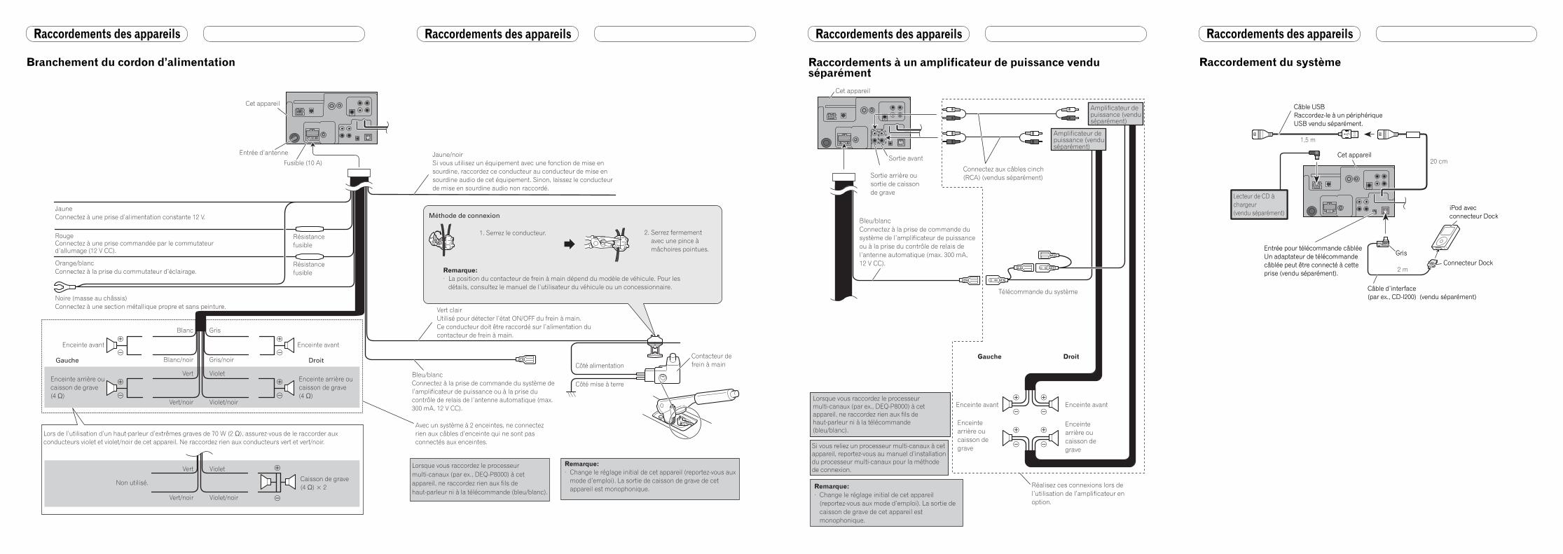
Branchement du cordon d’alimentation
JauneConnectez à une prise d’alimentation constante 12 V.
Rouge Connectez à une prise commandée par le commutateur d’allumage (12 V CC).
Noire (masse au châssis)Connectez à une section métallique propre et sans peinture.
Orange/blancConnectez à la prise du commutateur d’éclairage.
Fusible (10 A)
Cet appareil
Entrée d’antenne
Résistance fusible
Résistance fusible
Gauche Droit
Enceinte avant Enceinte avant
Enceinte arrière ou caisson de grave (4 Ω)
Blanc Gris
Gris/noirBlanc/noir
Vert Violet
Vert/noir Violet/noir
Enceinte arrière ou caisson de grave (4 Ω)
Violet
Violet/noir
Non utilisé.
Vert
Vert/noir
Lors de l’utilisation d’un haut-parleur d’extrêmes graves de 70 W (2 Ω), assurez-vous de le raccorder aux conducteurs violet et violet/noir de cet appareil. Ne raccordez rien aux conducteurs vert et vert/noir.
Caisson de grave (4 Ω) × 2
Bleu/blancConnectez à la prise de commande du système de l’amplificateur de puissance ou à la prise du contrôle de relais de l’antenne automatique (max. 300 mA, 12 V CC).
Lorsque vous raccordez le processeur multi-canaux (par ex., DEQ-P8000) à cet appareil, ne raccordez rien aux fils de haut-parleur ni à la télécommande (bleu/blanc).
Avec un système à 2 enceintes, ne connectez rien aux câbles d’enceinte qui ne sont pas connectés aux enceintes.
Remarque:· Change le réglage initial de cet appareil (reportez-vous aux
mode d’emploi). La sortie de caisson de grave de cet appareil est monophonique.
Méthode de connexion
1. Serrez le conducteur. 2. Serrez fermement avec une pince à mâchoires pointues.
Remarque: · La position du contacteur de frein à main dépend du modèle de véhicule. Pour les
détails, consultez le manuel de l’utilisateur du véhicule ou un concessionnaire.
Jaune/noirSi vous utilisez un équipement avec une fonction de mise en sourdine, raccordez ce conducteur au conducteur de mise en sourdine audio de cet équipement. Sinon, laissez le conducteur de mise en sourdine audio non raccordé.
Vert clairUtilisé pour détecter l’état ON/OFF du frein à main. Ce conducteur doit être raccordé sur l’alimentation du contacteur de frein à main.
Côté mise à terre
Côté alimentationContacteur de frein à main
Raccordements des appareils Raccordements des appareils
Raccordements à un amplificateur de puissance vendu séparément
Bleu/blancConnectez à la prise de commande du système de l’amplificateur de puissance ou à la prise du contrôle de relais de l’antenne automatique (max. 300 mA, 12 V CC).
Remarque:· Change le réglage initial de cet appareil
(reportez-vous aux mode d’emploi). La sortie de caisson de grave de cet appareil est monophonique.
Lorsque vous raccordez le processeur multi-canaux (par ex., DEQ-P8000) à cet appareil, ne raccordez rien aux fils de haut-parleur ni à la télécommande (bleu/blanc).
Cet appareil
Connectez aux câbles cinch (RCA) (vendus séparément)
Enceinte arrière ou caisson de grave
Réalisez ces connexions lors de l’utilisation de l’amplificateur en option.
Télécommande du système
Enceinte avant Enceinte avant
Gauche Droit
Sortie avant
Si vous reliez un processeur multi-canaux à cet appareil, reportez-vous au manuel d’installation du processeur multi-canaux pour la méthode de connexion.
Enceinte arrière ou caisson de grave
Amplificateur de puissance (vendu séparément)
Amplificateur de puissance (vendu séparément)
Sortie arrière ou sortie de caisson de grave
Raccordements des appareils
Raccordement du système
iPod avec connecteur Dock
Connecteur Dock
Câble d’interface (par ex., CD-I200) (vendu séparément)
Gris
Cet appareil
Câble USBRaccordez-le à un périphérique USB vendu séparément.
Entrée pour télécommande câbléeUn adaptateur de télécommande câblée peut être connecté à cette prise (vendu séparément).
1,5 m
20 cm
2 m
iPod avec connecteur Dock
Connecteur Dock
Câble d’interface (par ex., CD-I200) (vendu séparément)
Gris
Cet appareil
Câble USBRaccordez-le à un périphérique USB vendu séparément.
Entrée pour télécommande câbléeUn adaptateur de télécommande câblée peut être connecté à cette prise (vendu séparément).
Lecteur de CD à chargeur (vendu séparément)
Raccordements des appareils
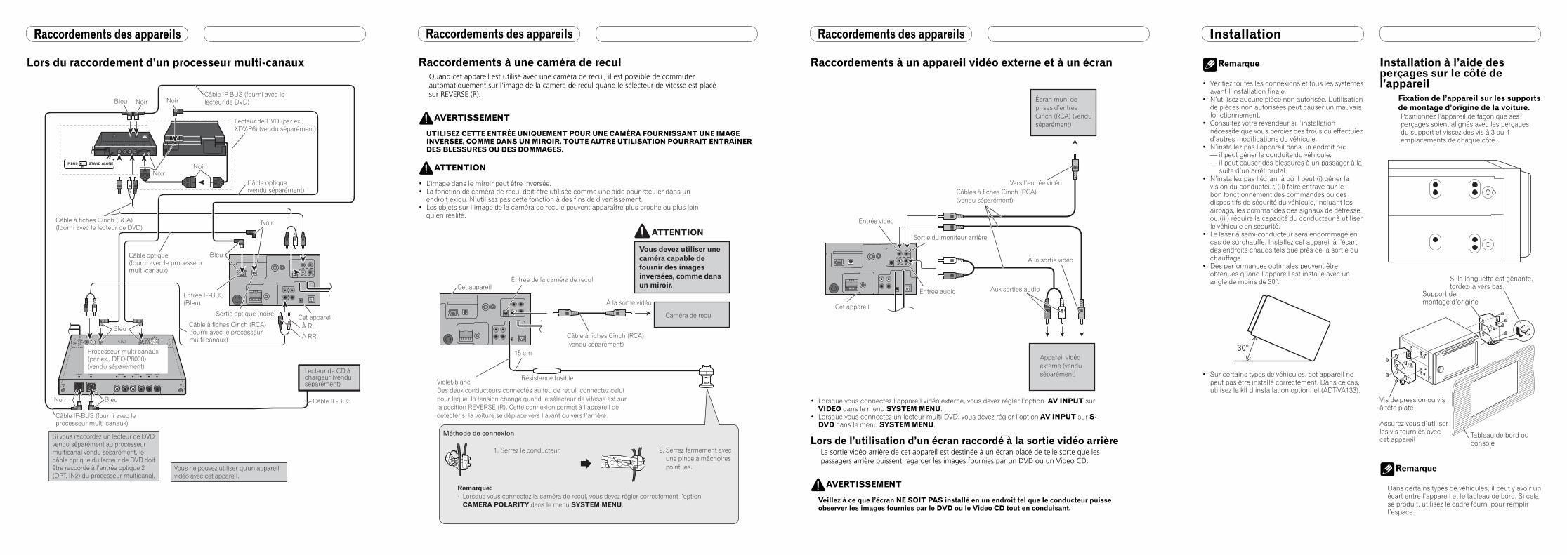
Raccordements à une caméra de reculQuand cet appareil est utilisé avec une caméra de recul, il est possible de commuter automatiquement sur l’image de la caméra de recul quand le sélecteur de vitesse est placé sur REVERSE (R).
AVERTISSEMENT
UTILISEZ CETTE ENTRÉE UNIQUEMENT POUR UNE CAMÉRA FOURNISSANT UNE IMAGE INVERSÉE, COMME DANS UN MIROIR. TOUTE AUTRE UTILISATION POURRAIT ENTRAÎNER DES BLESSURES OU DES DOMMAGES.
ATTENTION
• L’image dans le miroir peut être inversée.• La fonction de caméra de recul doit être utilisée comme une aide pour reculer dans un
endroit exigu. N’utilisez pas cette fonction à des fins de divertissement.• Les objets sur l’image de la caméra de recule peuvent apparaître plus proche ou plus loin
qu’en réalité.
Vous devez utiliser une caméra capable de fournir des images inversées, comme dans un miroir.
ATTENTION
15 cm
Câble à fiches Cinch (RCA)(vendu séparément)
À la sortie vidéo
Caméra de recul
Entrée de la caméra de reculCet appareil
Violet/blancDes deux conducteurs connectés au feu de recul, connectez celui pour lequel la tension change quand le sélecteur de vitesse est sur la position REVERSE (R). Cette connexion permet à l’appareil de détecter si la voiture se déplace vers l’avant ou vers l’arrière.
Résistance fusible
Méthode de connexion
1. Serrez le conducteur. 2. Serrez fermement avec une pince à mâchoires pointues.
Remarque:· Lorsque vous connectez la caméra de recul, vous devez régler correctement l’option
CAMERA POLARITY dans le menu SYSTEM MENU.
Raccordements des appareils
Lors du raccordement d’un processeur multi-canaux
Bleu
Processeur multi-canaux (par ex., DEQ-P8000) (vendu séparément)
NoirNoir
Lecteur de DVD (par ex., XDV-P6) (vendu séparément)
Sortie optique (noire) Cet appareil
Câble IP-BUS (fourni avec le processeur multi-canaux)
Noir Bleu
Câble IP-BUS (fourni avec le lecteur de DVD)
Câble optique (vendu séparément)
Câble à fiches Cinch (RCA)(fourni avec le processeur multi-canaux)
Câble à fiches Cinch (RCA) (fourni avec le lecteur de DVD)
Câble optique (fourni avec le processeur multi-canaux)
Bleu
Entrée IP-BUS (Bleu)
Noir
Lecteur de CD à chargeur (vendu séparément)
Câble IP-BUS
NoirNoirBleu
Si vous raccordez un lecteur de DVD vendu séparément au processeur multicanal vendu séparément, le câble optique du lecteur de DVD doit être raccordé à l’entrée optique 2 (OPT. IN2) du processeur multicanal.
Vous ne pouvez utiliser qu'un appareil vidéo avec cet appareil.
À RL
À RR
Raccordements des appareils
Raccordements à un appareil vidéo externe et à un écran
Appareil vidéo externe (vendu séparément)
Câbles à fiches Cinch (RCA) (vendu séparément)
Entrée audio
Écran muni de prises d’entrée Cinch (RCA) (vendu séparément)
Vers l’entrée vidéo
À la sortie vidéo
Aux sorties audio
Entrée vidéo
Cet appareil
Sortie du moniteur arrière
• Lorsque vous connectez l’appareil vidéo externe, vous devez régler l’option AV INPUT sur VIDEO dans le menu SYSTEM MENU.
• Lorsque vous connectez un lecteur multi-DVD, vous devez régler l’option AV INPUT sur S-DVD dans le menu SYSTEM MENU.
Lors de l’utilisation d’un écran raccordé à la sortie vidéo arrièreLa sortie vidéo arrière de cet appareil est destinée à un écran placé de telle sorte que les passagers arrière puissent regarder les images fournies par un DVD ou un Video CD.
AVERTISSEMENT
Veillez à ce que l’écran NE SOIT PAS installé en un endroit tel que le conducteur puisse observer les images fournies par le DVD ou le Video CD tout en conduisant.
Installation
Remarque
• Vérifiez toutes les connexions et tous les systèmes avant l’installation finale.
• N’utilisez aucune pièce non autorisée. L’utilisation de pièces non autorisées peut causer un mauvais fonctionnement.
• Consultez votre revendeur si l’installation nécessite que vous perciez des trous ou effectuiez d’autres modifications du véhicule.
• N’installez pas l’appareil dans un endroit où: — il peut gêner la conduite du véhicule.— il peut causer des blessures à un passager à la
suite d’un arrêt brutal.• N’installez pas l’écran là où il peut (i) gêner la
vision du conducteur, (ii) faire entrave aur le bon fonctionnement des commandes ou des dispositifs de sécurité du véhicule, incluant les airbags, les commandes des signaux de détresse, ou (iii) réduire la capacité du conducteur à utiliser le véhicule en sécurité.
• Le laser à semi-conducteur sera endommagé en cas de surchauffe. Installez cet appareil à l’écart des endroits chauds tels que près de la sortie du chauffage.
• Des performances optimales peuvent être obtenues quand l’appareil est installé avec un angle de moins de 30°.
• Sur certains types de véhicules, cet appareil ne peut pas être installé correctement. Dans ce cas, utilisez le kit d’installation optionnel (ADT-VA133).
Installation à l’aide des perçages sur le côté de l’appareil
Fixation de l’appareil sur les supports de montage d’origine de la voiture.Positionnez l’appareil de façon que ses perçages soient alignés avec les perçages du support et vissez des vis à 3 ou 4 emplacements de chaque côté.
Remarque
Dans certains types de véhicules, il peut y avoir un écart entre l’appareil et le tableau de bord. Si cela se produit, utilisez le cadre fourni pour remplir l’espace.
Support de montage d’origine
Si la languette est gênante, tordez-la vers bas.
Tableau de bord ou console
Vis de pression ou vis à tête plate
Assurez-vous d’utiliser les vis fournies avec cet appareil