Embed Size (px)
Citation preview

www.lge.com
INSTALLATION MANUAL
CHILLERAIR-COOLED SCREW
MODEL: MCAW(B) Series
• Please read this installation manual completely before installing the product.
• Installation work must be performed in accordance with the national wiring standards by authorized personnel only.
• Please retain this installation manual for future reference after reading it thoroughly.
ENG
LISH
2
ENG
LISH
For your recordsStaple your receipt to this page in case you need it to prove the date of purchase or for warranty purposes. Write the model number and the serial number here:
Model number :
Serial number :
You can find them on a label on the side of each unit.
Dealer’s name :
Date of purchase :
1. PRECAUTIONS BEFORE INSTALLATION 3
1. WARNING AND CAUTIONREAD ALL INSTRUCTIONS BEFORE USING THE APPLIANCE.Always comply with the following precautions to avoid dangerous situations and ensure peak per-formance of your product
WARNING
This symbol indicates the possibility of death or serious injury.
CAUTION
This symbol indicates the possibility of injury or damage to properties only.
Meanings of symbols used in this manual are as shown below.
Be sure to follow the instruction.
Be sure not to do.
WARNING• All wiring must comply with local requirements and the instructions given in this manual.
- If the power source capacity is inadequate or electric work is performed improperly, electric shock or fire may re-sult.
• Ask the dealer or an authorized technician to install the chiller.- Improper installation by the user may result in water leakage, electric shock, or fire.
• Always ground the product.- There is risk of fire or electric shock.
• Always install dedicated circuit and breaker.- Improper wiring or installation may cause fire or electric shock.
• For re-installation of the installed product, always contact a dealer or an Authorized Service Center.- There is risk of fire, electric shock, explosion, or injury.
• Do not install, remove, or re-install the unit by yourself(customer).- There is risk of fire, electric shock, explosion, or injury.
• Do not store or use flammable gas or combustibles near the chiller.- There is risk of fire or failure of product.
• Use the correctly rated breaker or fuse.- There is risk of fire or electric shock.
• Do not install the product on a defective installation stand.- It may cause injury, accident, or damage to the product.
• When installing and moving the chiller to another site, do not charge it with a different refrigerant from the refriger-ant specified on the unit.
- If a different refrigerant or air is mixed with the original refrigerant, the refrigerant cycle may malfunction and theunit may be damaged.
• Do not reconstruct to change the settings of the protection devices.- If the pressure switch, thermal switch, or other protection device is shorted and operated forcibly, or parts otherthan those specified by LGE are used, fire or explosion may result.
• Ventilate before operating chiller when gas leaked out.- It may cause explosion, fire, and burn.
!
!
!
ENG
LISH
4 1. PRECAUTIONS BEFORE INSTALLATION
ENG
LISH
• Securely install the cover of control box and the panel.- If the cover and panel are not installed securely, dust or water may enter the air-cooled unit and fire or electricshock may result.
• If the chiller is installed in a small room, measures must be taken to prevent the refrigerant concentration from ex-ceeding the safety limit when the refrigerant leaks.- Consult the dealer regarding the appropriate measures to prevent the safety limit from being exceeded. Shouldthe refrigerant leak and cause the safety limit to be exceeded, hazards due to lack of oxygen in the room could re-sult.
• Use a dedicated outlet for this appliance.- There is risk of fire or electrical shock.
• Be cautious that water could not enter the product.- There is risk of fire, electric shock, explosion, or injury.
• Do not touch the power switch with wet hands.- There is risk of fire, electric shock, explosion, or injury.
• When the product is soaked (flooded or submerged), contact an Authorized Service Center.- There is risk of fire or electric shock.
• Take care to ensure that nobody could step on or fall into the air-cooled unit.- This could result in personal injury and product damage.
• Follow the permitted pressure level- Follow the regulated pressure for chilled water, cooling water, refrigerant etc.- It can cause electricity leakage or burn/frostbite eruption or leakage.
• Be cautious of fire, earthquake and lightning- If there is natural disaster such as fire or earth-quake, or risk of lightning, immediately stop operating the unit- If you continue to operate the unit, it can cause a fire or electric shock.
• Be careful of the rotating part- Be careful not to put your finger or a stick in the rotating part of the fan or pump.- Do not operating the fan with the protective net removed. It can cause body injury.
• Use of undesignated refrigerant and oil is prohibited.- Do not use undesignated refrigerant, freezer oil and brine.- It can have a critical effect on the compressor and component defects.- If you would like to use a substitute for the refrigerant, please contact the manufacturer.
• Redesigning the control box is prohibited- Lock the control box with possible locking device and if you need to open the control box inevitably, turn off themain power first.
- Do not touch the wiring or parts within the control box.- It can cause electric shock, fire or defects.
• Be careful of leakage- If you find a leakage in the connected part such as pump, piping etc., immediately stop the operation.- It can cause electric shock, leakage or defects.
• Changing the set value is prohibited - Do not change the set value of the safety device.- If you operate the product with incorrectly set values, it can cause defect, fire or explosion.- When you change the control setting value, please consult with the specialized expert.
• Electric shock prevention- When installing the freezer, always ground the wire.- It can cause electric shock.
• Follow all safety codes- When working on this equipment, observe precautions in the literature, and on tags, stickers, and labels attachedto the equipment, and any other safety precautions that apply.
• Wear safety equipment- Wear safety glasses and work gloves.- Use care in handing, rigging, and setting this equipment, and in handling all electrical components.
• Shut off all power to this equipment during installation and service. - Electrical shock can cause personal injury and death.
1. PRECAUTIONS BEFORE INSTALLATION 5
- There may be more than one disconnect switch. Tag all disconnect locations to alert others not to restore poweruntil work is completed.
• Always run fluid through heat exchangers when adding or removing refrigerant charge.- It prevents potential damage to heat exchanger tubes.- Use appropriate brine solutions in cooler fluid loops to prevent the freezing of heat exchangers when the equip-ment is exposed to temperatures below 32°F (0°C).
• Do not vent refrigerant relief valves within a building.- Outlet from relief valves must be vented outdoors in accordance with the latest edition of ANSI/ASHRAE (Ameri-can National Standards Institute/American Society of Heating, Refrigeration and Air Conditioning Engineers) 15(Safety Code for Mechanical Refrigeration).
- The accumulation of refrigerant in an enclosed space can displace oxygen and cause asphyxiation.- Provide adequate ventilation in enclosed or low overhead areas. Inhalation of high concentrations of vapor is harm-ful and may cause heart irregularities, unconsciousness or death. Misuse can be fatal. Vapor is heavier than air andreduces the amount of oxygen available for breathing. Product causes eye and skin irritation.
• Do not attempt to umbrage factory joints when servicing this equipment. Cut lines with a tubing cutter as requiredwhen performing service.- Compressor oil is flammable and there is no way to detect how much oil may be in any of the refrigerant lines.- Use a pan to catch any oil that may come out of the lines and as a gage for how much oil to add to system.
• Do not re-use compressor oil.- It may cause damage to the product.
• Do not leave refrigerant system open to air any longer than necessary.- Seal circuits being serviced and charge with dry nitrogen to prevent oil contamination when timely repairs cannotbe completed.
CAUTIONInstallation• Always check for gas (refrigerant) leakage after installation or repair of product.
- Low refrigerant levels may cause failure of product.• Do not install the product where the noise or hot air from the air-cooled unit could damage the neighborhoods.
- It may cause a problem for your neighbors.• Keep level even when installing the product.
- To avoid vibration or water leakage.• Do not install the unit where combustible gas may leak.
- If the gas leaks and accumulates around the unit, an explosion may result.• Use power cables of sufficient current carrying capacity and rating.
- Cables that are too small may leak, generate heat, and cause a fire.• Do not use the product for special purposes, such as preserving foods, works of art, etc. It is a consumer chiller,
not a precision refrigeration system.- There is risk of damage or loss of property.
• Keep the unit away from children.- It can cause the injury, such as cutting the finger. Also the damaged fin may result in degradation of capacity.
• When installing the unit in a hospital, communication station, or similar place, provide sufficient protection againstnoise.- The inverter equipment, private power generator, high-frequency medical equipment, or radio communicationequipment may cause the chiller to operate erroneously, or fail to operate. On the other hand, the chiller may af-fect such equipment by creating noise that disturbs medical treatment or image broadcasting.
• Do not install the product where it is exposed to sea wind (salt spray) directly.- It may cause corrosion on the product. Corrosion could cause product malfunction or inefficient operation.
• Do not use the chiller in special environments.- Oil, steam, sulfuric smoke, etc. can significantly reduce the performance of the chiller or damage its parts.
• Make the connections securely so that the outside force of the cable may not be applied to the terminals.- Inadequate connection and fastening may generate heat and cause a fire.
• Be sure the installation area does not deteriorate with age.- If the base collapses, the chiller could fall with it, causing property damage, product failure, or personal injury.
ENG
LISH
6 1. PRECAUTIONS BEFORE INSTALLATION
ENG
LISH
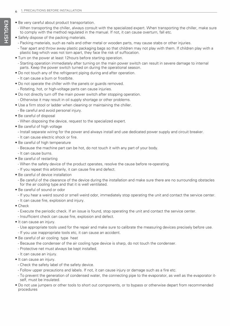
• Be very careful about product transportation.- When transporting the chiller, always consult with the specialized expert. When transporting the chiller, make sureto comply with the method regulated in the manual. If not, it can cause overturn, fall etc.
• Safely dispose of the packing materials.- Packing materials, such as nails and other metal or wooden parts, may cause stabs or other injuries.- Tear apart and throw away plastic packaging bags so that children may not play with them. If children play with aplastic bag which was not torn apart, they face the risk of suffocation.
• Turn on the power at least 12hours before starting operation.- Starting operation immediately after turning on the main power switch can result in severe damage to internalparts. Keep the power switch turned on during the operational season.
• Do not touch any of the refrigerant piping during and after operation.- It can cause a burn or frostbite.
• Do not operate the chiller with the panels or guards removed.- Rotating, hot, or high-voltage parts can cause injuries.
• Do not directly turn off the main power switch after stopping operation.- Otherwise it may result in oil supply shortage or other problems.
• Use a firm stool or ladder when cleaning or maintaining the chiller.- Be careful and avoid personal injury.
• Be careful of disposal- When disposing the device, request to the specialized expert.
• Be careful of high voltage - Install separate wiring for the power and always install and use dedicated power supply and circuit breaker.- It can cause electric shock or fire.
• Be careful of high temperature- Because the machine part can be hot, do not touch it with any part of your body.- It can cause burns.
• Be careful of restarting- When the safety device of the product operates, resolve the cause before re-operating.- If you repeat this arbitrarily, it can cause fire and defect.
• Be careful of device installation- Be careful of the clearance of the device during the installation and make sure there are no surrounding obstaclesfor the air cooling type and that it is well ventilated.
• Be careful of sound or odor- If you hear a weird sound or smell weird odor, immediately stop operating the unit and contact the service center.- It can cause fire, explosion and injury.
• Check - Execute the periodic check. If an issue is found, stop operating the unit and contact the service center.- Insufficient check can cause fire, explosion and defect.
• It can cause an injury. - Use appropriate tools used for the repair and make sure to calibrate the measuring devices precisely before use.- If you use inappropriate tools etc, it can cause an accident.
• Be careful of air cooling type heat - Because the condenser of the air cooling type device is sharp, do not touch the condenser.- Protective net must always be kept installed.- It can cause an injury.
• It can cause an injury. - Check the safety label of the safety device.- Follow upper precautions and labels. If not, it can cause injury or damage such as a fire etc.- To prevent the generation of condensed water, the connecting pipe to the evaporator, as well as the evaporator it-self, must be insulated.
• Do not use jumpers or other tools to short out components, or to bypass or otherwise depart from recommendedprocedures
1. PRECAUTIONS BEFORE INSTALLATION 7
ENG
LISH
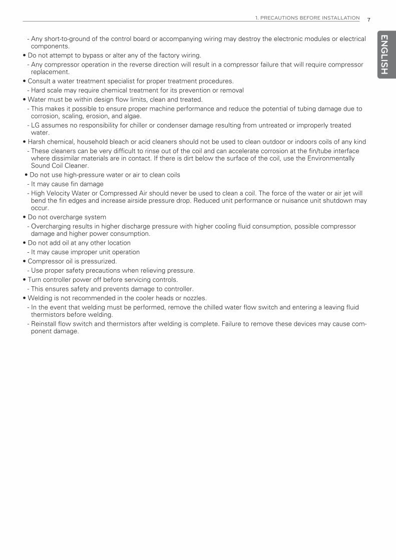
- Any short-to-ground of the control board or accompanying wiring may destroy the electronic modules or electricalcomponents.
• Do not attempt to bypass or alter any of the factory wiring.- Any compressor operation in the reverse direction will result in a compressor failure that will require compressorreplacement.
• Consult a water treatment specialist for proper treatment procedures.- Hard scale may require chemical treatment for its prevention or removal
• Water must be within design flow limits, clean and treated.- This makes it possible to ensure proper machine performance and reduce the potential of tubing damage due tocorrosion, scaling, erosion, and algae.
- LG assumes no responsibility for chiller or condenser damage resulting from untreated or improperly treatedwater.
• Harsh chemical, household bleach or acid cleaners should not be used to clean outdoor or indoors coils of any kind- These cleaners can be very difficult to rinse out of the coil and can accelerate corrosion at the fin/tube interfacewhere dissimilar materials are in contact. If there is dirt below the surface of the coil, use the EnvironmentallySound Coil Cleaner.
• Do not use high-pressure water or air to clean coils- It may cause fin damage- High Velocity Water or Compressed Air should never be used to clean a coil. The force of the water or air jet willbend the fin edges and increase airside pressure drop. Reduced unit performance or nuisance unit shutdown mayoccur.
• Do not overcharge system- Overcharging results in higher discharge pressure with higher cooling fluid consumption, possible compressordamage and higher power consumption.
• Do not add oil at any other location- It may cause improper unit operation
• Compressor oil is pressurized.- Use proper safety precautions when relieving pressure.
• Turn controller power off before servicing controls.- This ensures safety and prevents damage to controller.
• Welding is not recommended in the cooler heads or nozzles.- In the event that welding must be performed, remove the chilled water flow switch and entering a leaving fluidthermistors before welding.
- Reinstall flow switch and thermistors after welding is complete. Failure to remove these devices may cause com-ponent damage.

8 TABLE OF CONTENTS
ENG
LISH 3 1. WARNING AND CAU-
TION3 WARNING
5 CAUTION
9 2. NOMENCLATURE
10 3. SELECT INSTALLATIONLOCATION
10 Precaution when selecting the installation lo-cation
11 4. TRANSPORTATIONMETHOD
12 5. INSTALLATION12 Storage
12 Install and mount unit
16 Specification (50 Hz)
22 Specification (60 Hz)
28 Dimensional Drawings
35 Foundation
41 2 Unit Assembly
43 Cooler fluid piping connections
46 Filled chilled water loop
49 Wiring Diagram (Control box)
50 Wiring Diagram (Power box)
51 Electrical Data(50Hz)
52 Electrical Data(60Hz)
53 Electrical Connections
54 Standard and Options
55 Leak test unit
55 Refrigerant charging
55 Oil charging
TABLE OF CONTENTS
9
ENG
LISHIdentification Rule
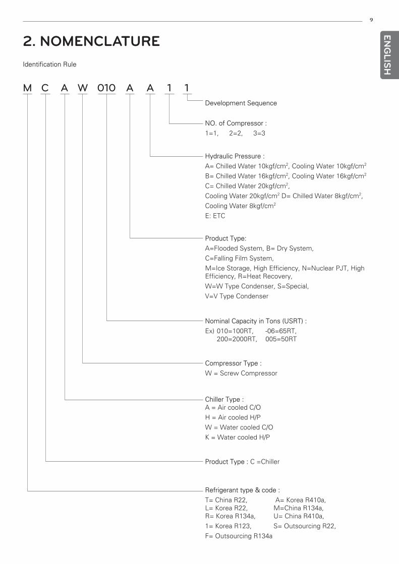
M C A W 010 A A 1 1Development Sequence
NO. of Compressor :
1=1, 2=2, 3=3
Hydraulic Pressure :
A= Chilled Water 10kgf/cm2, Cooling Water 10kgf/cm2
B= Chilled Water 16kgf/cm2, Cooling Water 16kgf/cm2
C= Chilled Water 20kgf/cm2,
Cooling Water 20kgf/cm2 D= Chilled Water 8kgf/cm2,
Cooling Water 8kgf/cm2
E: ETC
Product Type:
A=Flooded System, B= Dry System,
C=Falling Film System,
M=Ice Storage, High Efficiency, N=Nuclear PJT, HighEfficiency, R=Heat Recovery,
W=W Type Condenser, S=Special,
V=V Type Condenser
Nominal Capacity in Tons (USRT) :
Ex) 010=100RT, -06=65RT, 200=2000RT, 005=50RT
Compressor Type :
W = Screw Compressor
Chiller Type :A = Air cooled C/O
H = Air cooled H/P
W = Water cooled C/O
K = Water cooled H/P
Product Type : C =Chiller
Refrigerant type & code :
T= China R22, A= Korea R410a, L= Korea R22, M=China R134a,R= Korea R134a, U= China R410a,
1= Korea R123, S= Outsourcing R22,
F= Outsourcing R134a
2. NOMENCLATURE
10
ENG
LISH
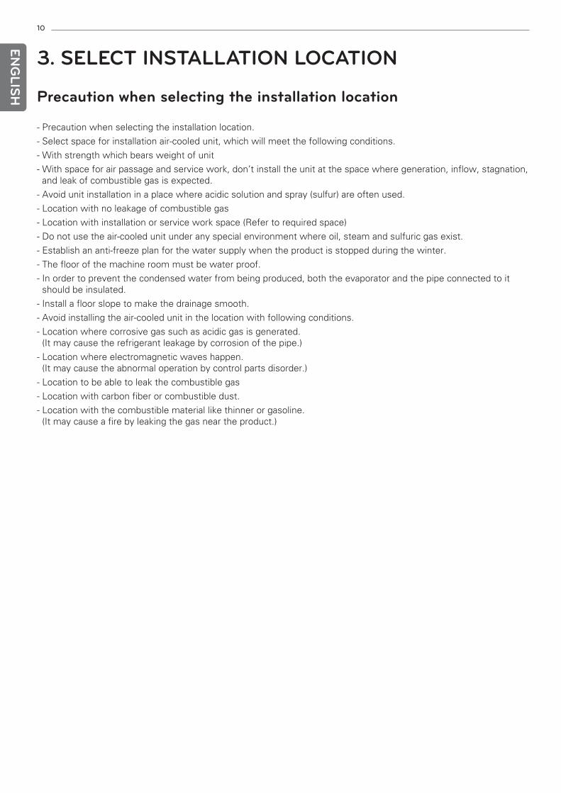
- Precaution when selecting the installation location.
- Select space for installation air-cooled unit, which will meet the following conditions.
- With strength which bears weight of unit
- With space for air passage and service work, don’t install the unit at the space where generation, inflow, stagnation,and leak of combustible gas is expected.
- Avoid unit installation in a place where acidic solution and spray (sulfur) are often used.
- Location with no leakage of combustible gas
- Location with installation or service work space (Refer to required space)
- Do not use the air-cooled unit under any special environment where oil, steam and sulfuric gas exist.
- Establish an anti-freeze plan for the water supply when the product is stopped during the winter.
- The floor of the machine room must be water proof.
- In order to prevent the condensed water from being produced, both the evaporator and the pipe connected to itshould be insulated.
- Install a floor slope to make the drainage smooth.
- Avoid installing the air-cooled unit in the location with following conditions.
- Location where corrosive gas such as acidic gas is generated. (It may cause the refrigerant leakage by corrosion of the pipe.)
- Location where electromagnetic waves happen.(It may cause the abnormal operation by control parts disorder.)
- Location to be able to leak the combustible gas
- Location with carbon fiber or combustible dust.
- Location with the combustible material like thinner or gasoline. (It may cause a fire by leaking the gas near the product.)
Precaution when selecting the installation location
3. SELECT INSTALLATION LOCATION
11
ENG
LISH
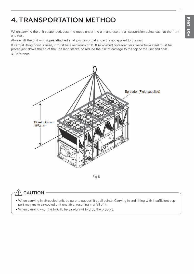
4. TRANSPORTATION METHODWhen carrying the unit suspended, pass the ropes under the unit and use the all suspension points each at the frontand rear.
Always lift the unit with ropes attached at all points so that impact is not applied to the unit
If central lifting point is used, it must be a minimum of 15 ft.(4572mm) Spreader bars made from steel must beplaced just above the tip of the unit (and stacks) to reduce the risk of damage to the top of the unit and coils.
❈ Reference
Fig 5
! CAUTION
• When carrying in air-cooled unit, be sure to support it at all points. Carrying in and lifting with insufficient sup-port may make air-cooled unit unstable, resulting in a fall of it.
• When carrying with the forklift, be careful not to drop the product.
12
ENG
LISH
If the unit is to be stored for a period of time before installation or start-up, be sure to protect the machine from con-struction dirt and moisture. Keep protective shipping covers in place until machine is ready for installation.
Inspect the unit upon arrival for damage. If damage is found, file a claim right away with the shipping company.
1. PLACING UNIT.
• When considering location for the unit, be sure to consult National Electrical Code (NEC, U.S.A.) and local code re-quirements or Electrical Code and local code requirements for each nation. Allow sufficient space for airflow,wiring, piping, and service. Be sure surface beneath the unit is level, and is capable of supporting the operatingweight of the unit. See specification, dimensional drawings and foundation for unit lifting points, mounting and op-erating weights.
• Locate the unit so that the condenser airflow is unrestricted both above and on the sides of the unit. Airflow andservice clearances around the unit are dependent on models. Provide ample room for servicing and removingcooler. Local codes for clearances take precedence over the manufacturer’s recommendations when local codescall for greater clearances.
• Modular units, MCAW045~050BA must be installed with a minimum separation end to end of 4 feet (1.3 m) for air-flow and service clearance along with NEC regulations.
• If multiple units are installed at the same site, a separation of 11.2 feet (3.4 m) between the sides of the machinesis required to maintain proper airflow and minimize the chances of condenser air recirculation.
2. MOUNTING UNIT
• The unit may be mounted on a level pad directly on the base rails, on rails along the long axis of the machine, or onvibration isolation springs. For all units, ensure placement area is strong enough to support unit operating weight.Mounting holes are provided for securing the unit to the pad or vibration isolation springs or pads. The base rail canbe point loaded at the mounting points.
• Bolt the unit securely to pad or rails. If vibration isolators or pads (field supplied) are required for a particular installa-tion, refer to unit weight of specification table to aid in the proper selection of isolators or pads. The MCAW unitscan be mounted directly on spring isolators. For each unit or module, the final unit location must be level so that oilwill equalize properly.
• If the unit was shipped with coil protection, it must be removed before start-up. The shipping bag for export unitsmust be removed before start-up.
! WARNING
• Be sure to install unit in a place strong enough to withstand its weight. Any lack of strength may cause unit tofall down, resulting in a personal injury.
• When carrying with the forklift, be careful not to drop the product.
• Have installation work in order to protect against a strong wind and earthquake. Any installation deficiency maycause unit to fall down, resulting in a personal injury.
• Especially take care for support strength of the floor surface, water drain processing (processing of waterflown out from the air-cooled unit during operation) and paths of the pipe and wiring when making a base sup-port.
Install and mount unit
Storage
5. INSTALLATION
13
ENG
LISH
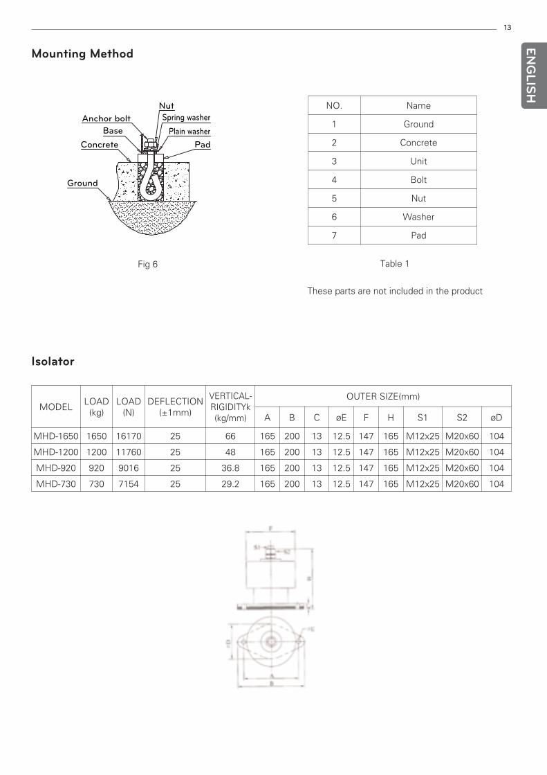
Mounting Method
Anchor bolt
Base
Concrete
Ground
Nut
Spring washer
Plain washer
Pad
NO. Name
1 Ground
2 Concrete
3 Unit
4 Bolt
5 Nut
6 Washer
7 Pad
Fig 6 Table 1
These parts are not included in the product
Isolator
MODELLOAD(kg)
LOAD(N)
DEFLECTION(±1mm)
VERTICAL-RIGIDITYk(kg/mm)
OUTER SIZE(mm)
A B C øE F H S1 S2 øD
MHD-1650 1650 16170 25 66 165 200 13 12.5 147 165 M12x25 M20x60 104
MHD-1200 1200 11760 25 48 165 200 13 12.5 147 165 M12x25 M20x60 104
MHD-920 920 9016 25 36.8 165 200 13 12.5 147 165 M12x25 M20x60 104
MHD-730 730 7154 25 29.2 165 200 13 12.5 147 165 M12x25 M20x60 104
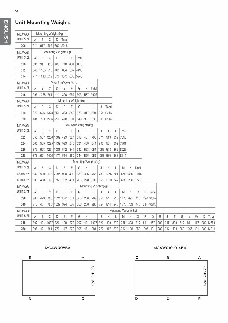
MCAW(B)UNIT SIZE
Mounting Weights(kg)
A B C D Total
008 811 817 697 693 3018
MCAW(B)UNIT SIZE
Mounting Weights(kg)
A B C D E F Total
010 531 911 436 407 710 481 3476
012 546 1185 519 485 894 507 4136
014 711 1613 632 579 1073 638 5246
MCAW(B)UNIT SIZE
Mounting Weights(kg)
A B C D E F G H Total
016 596 1328 791 411 390 667 905 537 5625
MCAW(B)UNIT SIZE
Mounting Weights(kg)
A B C D E F G H I J Total
018 370 676 1373 654 363 348 576 911 591 354 6216
020 404 733 1556 750 410 391 649 997 638 386 6914
MCAW(B)UNIT SIZE
Mounting Weights(kg)
A B C D E F G H I J K L Total
022 353 567 1256 1062 499 324 313 461 798 871 513 339 7356
024 366 585 1295 1132 529 343 331 488 844 905 531 352 7701
026 373 603 1251 1081 542 347 342 523 954 1065 578 366 8025
028 378 621 1406 1174 554 352 344 525 952 1063 580 368 8317
MCAW(B)UNIT SIZE
Mounting Weights(kg)
A B C D E F G H I J K L M N Total
030(50Hz) 337 500 932 2086 900 490 333 326 468 781 1254 801 476 330 10014
030(60Hz) 305 458 880 1753 732 411 283 278 395 650 1100 747 436 298 8726
MCAW(B)UNIT SIZE
Mounting Weights(kg)
A B C D E F G H I J K L M N O P Total
036 302 429 756 1624 1092 571 360 266 263 352 541 920 1176 691 416 298 10057
040 317 451 795 1539 994 553 356 266 265 354 544 946 1376 769 446 314 10285
MCAW(B)UNIT SIZE
Mounting Weights(kg)
A B C D E F G H I J K L M N O P Q R S T U V W X Total
045 307 494 1037 829 409 270 307 494 1037 829 409 270 265 393 717 841 467 300 265 393 717 841 467 300 12658
050 305 474 881 777 417 278 305 474 881 777 417 278 282 428 859 1006 491 309 282 428 859 1006 491 309 13014
14
ENG
LISH
Unit Mounting Weights
A
D
B
C
MCAW008BA
A
F
B
E
MCAW010-014BA
C
D
Control B
ox
Control B
ox
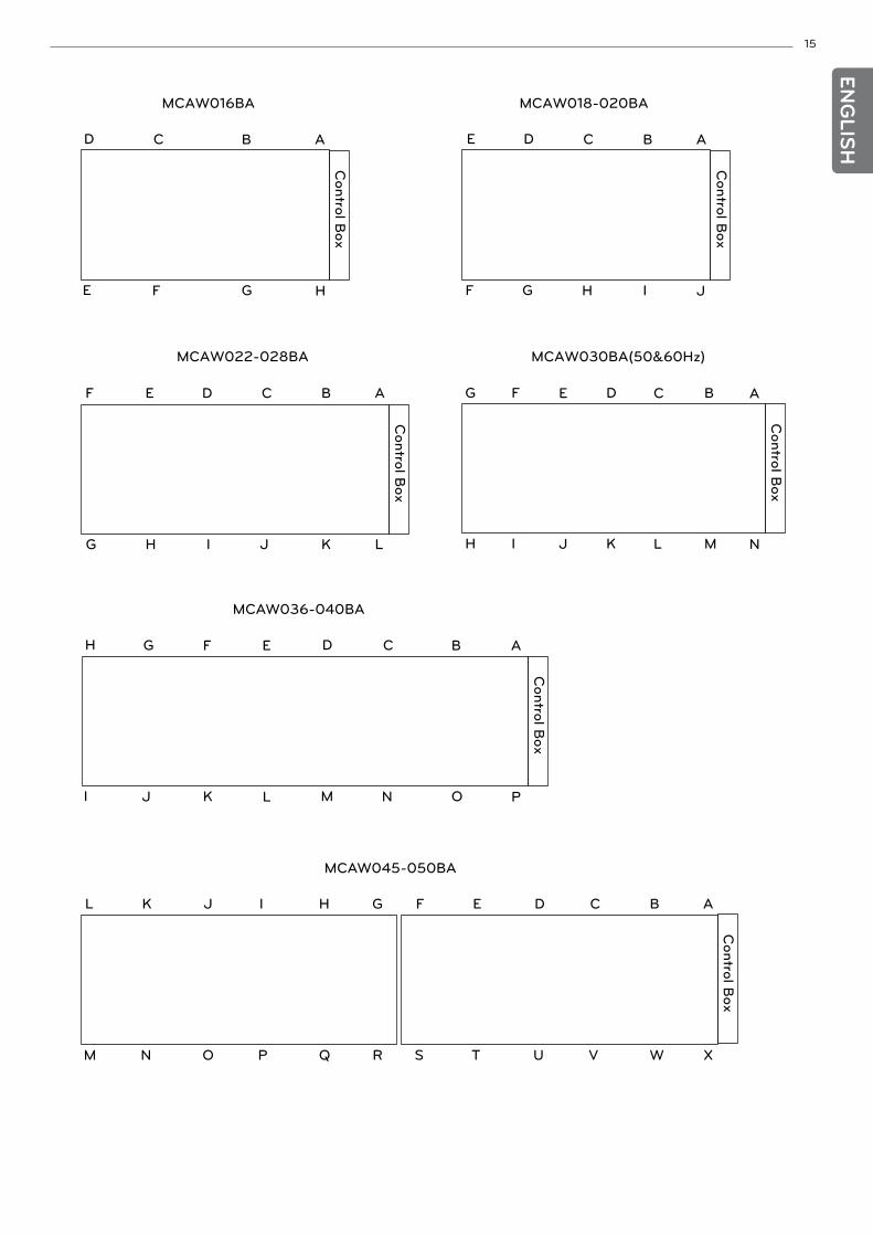
15EN
GLIS
H
A
P
B
O
MCAW036-040BA
C
N
D
M
E
L
F
K
G
J
H
I
MCAW045-050BA
A
X
B
W
C
V
D
U
E
T
F
S
Control B
ox
G
R
H
Q
I
P
J
O
K
N
L
M
Control B
ox
A
H
B
G
MCAW016BA
C
F
D
E
A
J
B
I
MCAW018-020BA
C
H
D
G
E
F
Control B
ox
A
L
B
K
CDE
JIHG
F
Control B
ox
Control B
ox
MCAW022-028BA
NM
MCAW030BA(50&60Hz)
LKJIH
ABCDEFG
Control B
ox
16
ENG
LISH
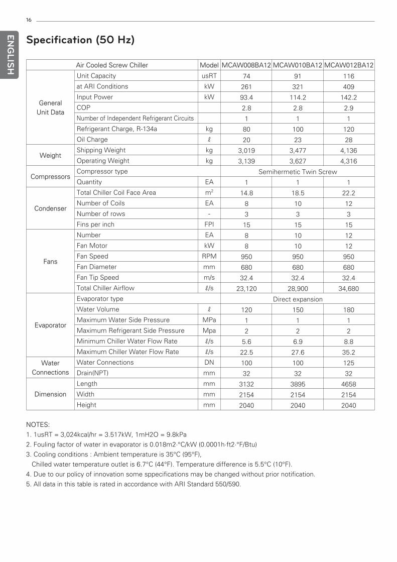
Specification (50 Hz)
Air Cooled Screw Chiller Model MCAW008BA12 MCAW010BA12 MCAW012BA12
GeneralUnit Data
Unit Capacity usRT
at ARI Conditions kW
Input Power kW
COP
Number of Independent Refrigerant Circuits
Refrigerant Charge, R-134a kg
Oil Charge ℓ
WeightShipping Weight kg
Operating Weight kg
CompressorsCompressor type
Quantity EA
Condenser
Total Chiller Coil Face Area m2
Number of Coils EA
Number of rows -
Fins per inch FPI
Fans
Number EA
Fan Motor kW
Fan Speed RPM
Fan Diameter mm
Fan Tip Speed m/s
Total Chiller Airflow ℓ/s
Evaporator
Evaporator type
Water Volume ℓ
Maximum Water Side Pressure MPa
Maximum Refrigerant Side Pressure Mpa
Minimum Chiller Water Flow Rate ℓ/s
Maximum Chiller Water Flow Rate ℓ/s
WaterConnections
Water Connections DN
Drain(NPT) mm
Dimension
Length mm
Width mm
Height mm
NOTES:
1. 1usRT = 3,024kcal/hr = 3.517kW, 1mH2O = 9.8kPa
2. Fouling factor of water in evaporator is 0.018m2·°C/kW (0.0001h·ft2·°F/Btu)
3. Cooling conditions : Ambient temperature is 35°C (95°F),
Chilled water temperature outlet is 6.7°C (44°F). Temperature difference is 5.5°C (10°F).
4. Due to our policy of innovation some sppecifications may be changed without prior notification.
5. All data in this table is rated in accordance with ARI Standard 550/590.
74 91 116
261 321 409
93.4 114.2 142.2
2.8 2.8 2.9
1 1 1
80 100 120
20 23 28
3,019 3,477 4,136
3,139 3,627 4,316
Semihermetic Twin Screw
1 1 1
14.8 18.5 22.2
8 10 12
3 3 3
15 15 15
8 10 12
8 10 12
950 950 950
680 680 680
32.4 32.4 32.4
23,120 28,900 34,680
Direct expansion
120 150 180
1 1 1
2 2 2
5.6 6.9 8.8
22.5 27.6 35.2
100 100 125
32 32 32
3132 3895 4658
2154 2154 2154
2040 2040 2040
17
ENG
LISH
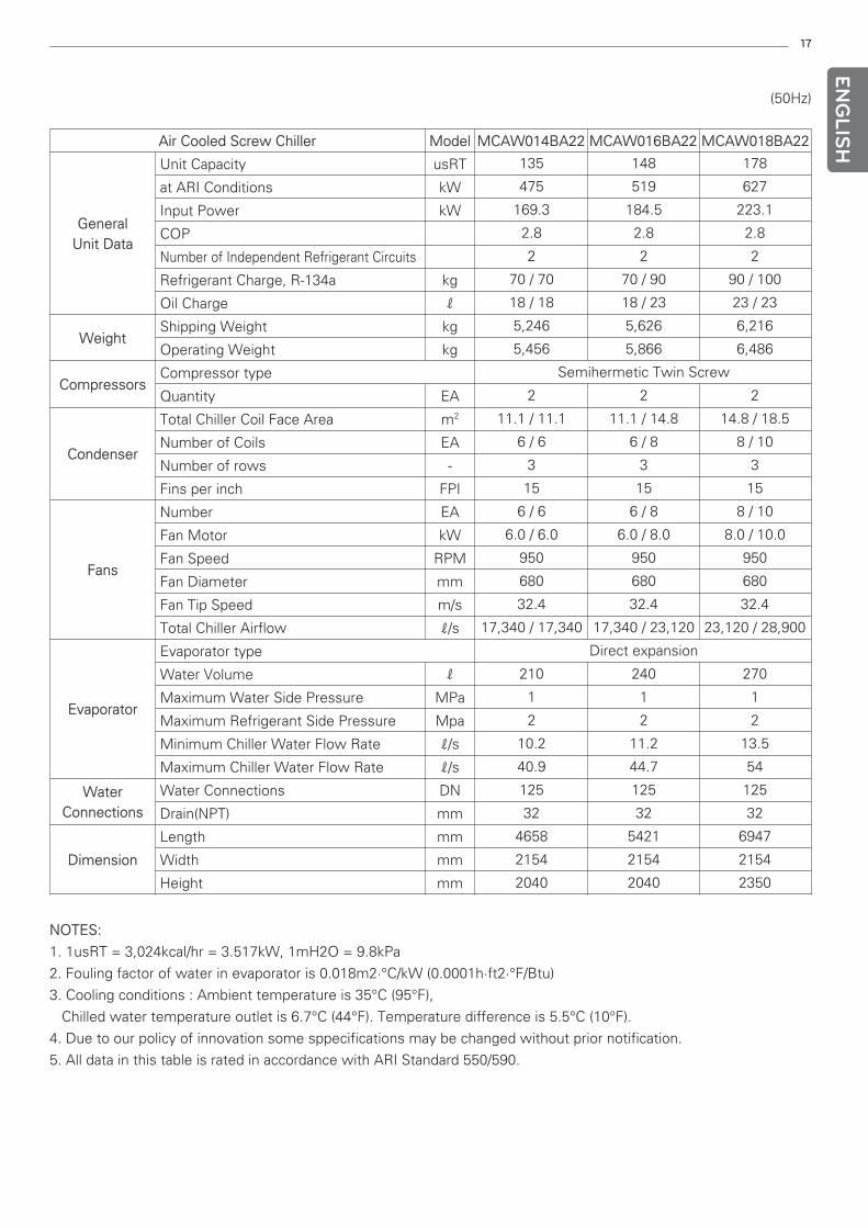
NOTES:
1. 1usRT = 3,024kcal/hr = 3.517kW, 1mH2O = 9.8kPa
2. Fouling factor of water in evaporator is 0.018m2·°C/kW (0.0001h·ft2·°F/Btu)
3. Cooling conditions : Ambient temperature is 35°C (95°F),
Chilled water temperature outlet is 6.7°C (44°F). Temperature difference is 5.5°C (10°F).
4. Due to our policy of innovation some sppecifications may be changed without prior notification.
5. All data in this table is rated in accordance with ARI Standard 550/590.
(50Hz)
Air Cooled Screw Chiller Model MCAW014BA22 MCAW016BA22 MCAW018BA22
GeneralUnit Data
Unit Capacity usRT
at ARI Conditions kW
Input Power kW
COP
Number of Independent Refrigerant Circuits
Refrigerant Charge, R-134a kg
Oil Charge ℓ
WeightShipping Weight kg
Operating Weight kg
CompressorsCompressor type
Quantity EA
Condenser
Total Chiller Coil Face Area m2
Number of Coils EA
Number of rows -
Fins per inch FPI
Fans
Number EA
Fan Motor kW
Fan Speed RPM
Fan Diameter mm
Fan Tip Speed m/s
Total Chiller Airflow ℓ/s
Evaporator
Evaporator type
Water Volume ℓ
Maximum Water Side Pressure MPa
Maximum Refrigerant Side Pressure Mpa
Minimum Chiller Water Flow Rate ℓ/s
Maximum Chiller Water Flow Rate ℓ/s
WaterConnections
Water Connections DN
Drain(NPT) mm
Dimension
Length mm
Width mm
Height mm
135 148 178
475 519 627
169.3 184.5 223.1
2.8 2.8 2.8
2 2 2
70 / 70 70 / 90 90 / 100
18 / 18 18 / 23 23 / 23
5,246 5,626 6,216
5,456 5,866 6,486
Semihermetic Twin Screw
2 2 2
11.1 / 11.1 11.1 / 14.8 14.8 / 18.5
6 / 6 6 / 8 8 / 10
3 3 3
15 15 15
6 / 6 6 / 8 8 / 10
6.0 / 6.0 6.0 / 8.0 8.0 / 10.0
950 950 950
680 680 680
32.4 32.4 32.4
17,340 / 17,340 17,340 / 23,120 23,120 / 28,900
Direct expansion
210 240 270
1 1 1
2 2 2
10.2 11.2 13.5
40.9 44.7 54
125 125 125
32 32 32
4658 5421 6947
2154 2154 2154
2040 2040 2350
18
ENG
LISH
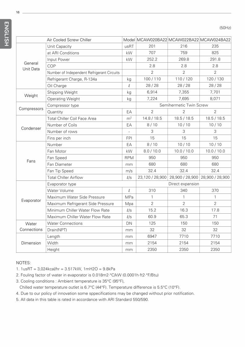
NOTES:
1. 1usRT = 3,024kcal/hr = 3.517kW, 1mH2O = 9.8kPa
2. Fouling factor of water in evaporator is 0.018m2·°C/kW (0.0001h·ft2·°F/Btu)
3. Cooling conditions : Ambient temperature is 35°C (95°F),
Chilled water temperature outlet is 6.7°C (44°F). Temperature difference is 5.5°C (10°F).
4. Due to our policy of innovation some sppecifications may be changed without prior notification.
5. All data in this table is rated in accordance with ARI Standard 550/590.
(50Hz)
Air Cooled Screw Chiller Model MCAW020BA22 MCAW022BA22 MCAW024BA22
GeneralUnit Data
Unit Capacity usRT
at ARI Conditions kW
Input Power kW
COP
Number of Independent Refrigerant Circuits
Refrigerant Charge, R-134a kg
Oil Charge ℓ
WeightShipping Weight kg
Operating Weight kg
CompressorsCompressor type
Quantity EA
Condenser
Total Chiller Coil Face Area m2
Number of Coils EA
Number of rows -
Fins per inch FPI
Fans
Number EA
Fan Motor kW
Fan Speed RPM
Fan Diameter mm
Fan Tip Speed m/s
Total Chiller Airflow ℓ/s
Evaporator
Evaporator type
Water Volume ℓ
Maximum Water Side Pressure MPa
Maximum Refrigerant Side Pressure Mpa
Minimum Chiller Water Flow Rate ℓ/s
Maximum Chiller Water Flow Rate ℓ/s
WaterConnections
Water Connections DN
Drain(NPT) mm
Dimension
Length mm
Width mm
Height mm
201 216 235
707 759 825
252.2 269.8 291.8
2.8 2.8 2.8
2 2 2
100 / 110 110 / 120 120 / 130
28 / 28 28 / 28 28 / 28
6,914 7,355 7,701
7,224 7,695 8,071
Semihermetic Twin Screw
2 2 2
14.8 / 18.5 18.5 / 18.5 18.5 / 18.5
8 / 10 10 / 10 10 / 10
3 3 3
15 15 15
8 / 10 10 / 10 10 / 10
8.0 / 10.0 10.0 / 10.0 10.0 / 10.0
950 950 950
680 680 680
32.4 32.4 32.4
23,120 / 28,900 28,900 / 28,900 28,900 / 28,900
Direct expansion
310 340 370
1 1 1
2 2 2
15.2 16.3 17.8
60.9 65.3 71
125 150 150
32 32 32
6947 7710 7710
2154 2154 2154
2350 2350 2350
19
ENG
LISH
NOTES:
1. 1usRT = 3,024kcal/hr = 3.517kW, 1mH2O = 9.8kPa
2. Fouling factor of water in evaporator is 0.018m2·°C/kW (0.0001h·ft2·°F/Btu)
3. Cooling conditions : Ambient temperature is 35°C (95°F),
Chilled water temperature outlet is 6.7°C (44°F). Temperature difference is 5.5°C (10°F).
4. Due to our policy of innovation some sppecifications may be changed without prior notification.
5. All data in this table is rated in accordance with ARI Standard 550/590.
(50Hz)
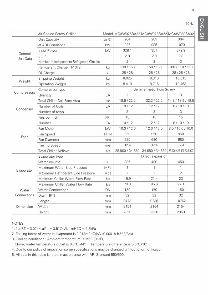
Air Cooled Screw Chiller Model MCAW026BA22 MCAW028BA22 MCAW030BA32
GeneralUnit Data
Unit Capacity usRT
at ARI Conditions kW
Input Power kW
COP
Number of Independent Refrigerant Circuits
Refrigerant Charge, R-134a kg
Oil Charge ℓ
WeightShipping Weight kg
Operating Weight kg
CompressorsCompressor type
Quantity EA
Condenser
Total Chiller Coil Face Area m2
Number of Coils EA
Number of rows -
Fins per inch FPI
Fans
Number EA
Fan Motor kW
Fan Speed RPM
Fan Diameter mm
Fan Tip Speed m/s
Total Chiller Airflow ℓ/s
Evaporator
Evaporator type
Water Volume ℓ
Maximum Water Side Pressure MPa
Maximum Refrigerant Side Pressure Mpa
Minimum Chiller Water Flow Rate ℓ/s
Maximum Chiller Water Flow Rate ℓ/s
WaterConnections
Water Connections DN
Drain(NPT) mm
Dimension
Length mm
Width mm
Height mm
264 283 304
927 995 1070
328.1 351 379.9
2.8 2.8 2.8
2 2 3
130 / 150 150 / 150 100 / 110 / 110
28 / 28 28 / 28 28 / 28 / 28
8,025 8,316 10,013
8,410 8,716 10,463
Semihermetic Twin Screw
2 2 3
18.5 / 22.2 22.2 / 22.2 14.8 / 18.5 / 18.5
10 / 12 12 / 12 8 / 10 / 10
3 3 3
15 15 15
10 / 12 12 / 12 8 / 10 / 10
10.0 / 12.0 12.0 / 12.0 8.0 / 10.0 / 10.0
950 950 950
680 680 680
32.4 32.4 32.4
28,900 / 34,680 34,680 / 34,680 23,120 / 28,900 / 28,900
Direct expansion
385 400 450
1 1 1
2 2 2
19.9 21.4 23
79.8 85.6 92.1
150 150 150
32 32 32
8473 9236 10762
2154 2154 2154
2350 2350 2350
20
ENG
LISH
NOTES:
1. 1usRT = 3,024kcal/hr = 3.517kW, 1mH2O = 9.8kPa
2. Fouling factor of water in evaporator is 0.018m2·°C/kW (0.0001h·ft2·°F/Btu)
3. Cooling conditions : Ambient temperature is 35°C (95°F),
Chilled water temperature outlet is 6.7°C (44°F). Temperature difference is 5.5°C (10°F).
4. Due to our policy of innovation some sppecifications may be changed without prior notification.
5. All data in this table is rated in accordance with ARI Standard 550/590.
(50Hz)
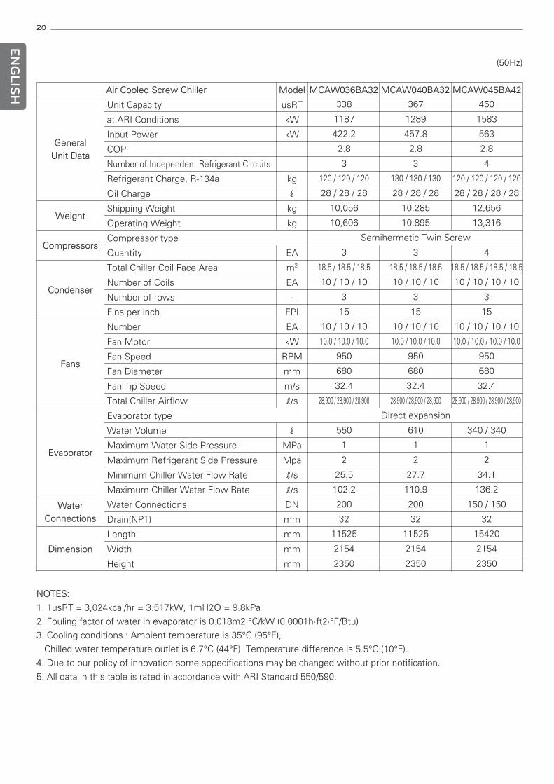
Air Cooled Screw Chiller Model MCAW036BA32 MCAW040BA32 MCAW045BA42
GeneralUnit Data
Unit Capacity usRT
at ARI Conditions kW
Input Power kW
COP
Number of Independent Refrigerant Circuits
Refrigerant Charge, R-134a kg
Oil Charge ℓ
WeightShipping Weight kg
Operating Weight kg
CompressorsCompressor type
Quantity EA
Condenser
Total Chiller Coil Face Area m2
Number of Coils EA
Number of rows -
Fins per inch FPI
Fans
Number EA
Fan Motor kW
Fan Speed RPM
Fan Diameter mm
Fan Tip Speed m/s
Total Chiller Airflow ℓ/s
Evaporator
Evaporator type
Water Volume ℓ
Maximum Water Side Pressure MPa
Maximum Refrigerant Side Pressure Mpa
Minimum Chiller Water Flow Rate ℓ/s
Maximum Chiller Water Flow Rate ℓ/s
WaterConnections
Water Connections DN
Drain(NPT) mm
Dimension
Length mm
Width mm
Height mm
338 367 450
1187 1289 1583
422.2 457.8 563
2.8 2.8 2.8
3 3 4
120 / 120 / 120 130 / 130 / 130 120 / 120 / 120 / 120
28 / 28 / 28 28 / 28 / 28 28 / 28 / 28 / 28
10,056 10,285 12,656
10,606 10,895 13,316
Semihermetic Twin Screw
3 3 4
18.5 / 18.5 / 18.5 18.5 / 18.5 / 18.5 18.5 / 18.5 / 18.5 / 18.5
10 / 10 / 10 10 / 10 / 10 10 / 10 / 10 / 10
3 3 3
15 15 15
10 / 10 / 10 10 / 10 / 10 10 / 10 / 10 / 10
10.0 / 10.0 / 10.0 10.0 / 10.0 / 10.0 10.0 / 10.0 / 10.0 / 10.0
950 950 950
680 680 680
32.4 32.4 32.4
28,900 / 28,900 / 28,900 28,900 / 28,900 / 28,900 28,900 / 28,900 / 28,900 / 28,900
Direct expansion
550 610 340 / 340
1 1 1
2 2 2
25.5 27.7 34.1
102.2 110.9 136.2
200 200 150 / 150
32 32 32
11525 11525 15420
2154 2154 2154
2350 2350 2350
21
ENG
LISH
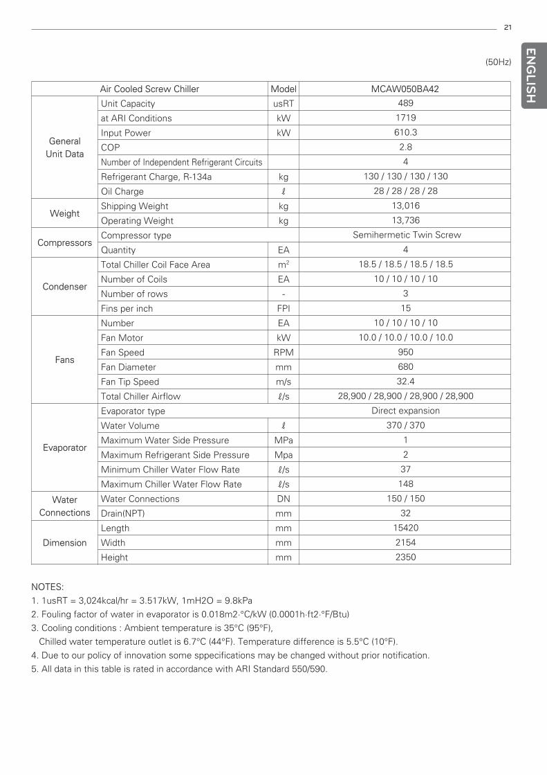
NOTES:
1. 1usRT = 3,024kcal/hr = 3.517kW, 1mH2O = 9.8kPa
2. Fouling factor of water in evaporator is 0.018m2·°C/kW (0.0001h·ft2·°F/Btu)
3. Cooling conditions : Ambient temperature is 35°C (95°F),
Chilled water temperature outlet is 6.7°C (44°F). Temperature difference is 5.5°C (10°F).
4. Due to our policy of innovation some sppecifications may be changed without prior notification.
5. All data in this table is rated in accordance with ARI Standard 550/590.
(50Hz)
Air Cooled Screw Chiller Model MCAW050BA42
GeneralUnit Data
Unit Capacity usRT
at ARI Conditions kW
Input Power kW
COP
Number of Independent Refrigerant Circuits
Refrigerant Charge, R-134a kg
Oil Charge ℓ
WeightShipping Weight kg
Operating Weight kg
CompressorsCompressor type
Quantity EA
Condenser
Total Chiller Coil Face Area m2
Number of Coils EA
Number of rows -
Fins per inch FPI
Fans
Number EA
Fan Motor kW
Fan Speed RPM
Fan Diameter mm
Fan Tip Speed m/s
Total Chiller Airflow ℓ/s
Evaporator
Evaporator type
Water Volume ℓ
Maximum Water Side Pressure MPa
Maximum Refrigerant Side Pressure Mpa
Minimum Chiller Water Flow Rate ℓ/s
Maximum Chiller Water Flow Rate ℓ/s
WaterConnections
Water Connections DN
Drain(NPT) mm
Dimension
Length mm
Width mm
Height mm
489
1719
610.3
2.8
4
130 / 130 / 130 / 130
28 / 28 / 28 / 28
13,016
13,736
Semihermetic Twin Screw
4
18.5 / 18.5 / 18.5 / 18.5
10 / 10 / 10 / 10
3
15
10 / 10 / 10 / 10
10.0 / 10.0 / 10.0 / 10.0
950
680
32.4
28,900 / 28,900 / 28,900 / 28,900
Direct expansion
370 / 370
1
2
37
148
150 / 150
32
15420
2154
2350

22
ENG
LISH
Specification (60 Hz)
Air Cooled Screw Chiller Model MCAW008BA12 MCAW010BA12 MCAW012BA12
GeneralUnit Data
Unit Capacity usRT
at ARI Conditions kW
Input Power kW
COP
Number of Independent Refrigerant Circuits
Refrigerant Charge, R-134a kg
Oil Charge ℓ
WeightShipping Weight kg
Operating Weight kg
CompressorsCompressor type
Quantity EA
Condenser
Total Chiller Coil Face Area m2
Number of Coils EA
Number of rows -
Fins per inch FPI
Fans
Number EA
Fan Motor kW
Fan Speed RPM
Fan Diameter mm
Fan Tip Speed m/s
Total Chiller Airflow ℓ/s
Evaporator
Evaporator type
Water Volume ℓ
Maximum Water Side Pressure MPa
Maximum Refrigerant Side Pressure Mpa
Minimum Chiller Water Flow Rate ℓ/s
Maximum Chiller Water Flow Rate ℓ/s
WaterConnections
Water Connections DN
Drain(NPT) mm
Dimension
Length mm
Width mm
Height mm
NOTES:
1. 1usRT = 3,024kcal/hr = 3.517kW, 1mH2O = 9.8kPa
2. Fouling factor of water in evaporator is 0.018m2·°C/kW (0.0001h·ft2·°F/Btu)
3. Cooling conditions : Ambient temperature is 35°C (95°F),
Chilled water temperature outlet is 6.7°C (44°F). Temperature difference is 5.5°C (10°F).
4. Due to our policy of innovation some sppecifications may be changed without prior notification.
5. All data in this table is rated in accordance with ARI Standard 550/590.
75 91 112
263 319 393
92.4 113 134.7
2.8 2.8 2.9
1 1 1
80 100 120
15 20 23
2,979 3,377 3,836
3,099 3,527 4,016
Semihermetic Twin Screw
1 1 1
14.8 18.5 22.2
8 10 12
3 3 3
15 15 15
8 10 12
10.8 13.5 16.2
1100 1100 1100
680 680 680
39.2 39.2 39.2
28,000 35,000 42,000
Direct expansion
120 150 180
1 1 1
2 2 2
5.7 6.9 8.5
22.6 27.5 33.8
100 100 125
32 32 32
3132 3895 4658
2154 2154 2154
2040 2040 2040

23
ENG
LISH
NOTES:
1. 1usRT = 3,024kcal/hr = 3.517kW, 1mH2O = 9.8kPa
2. Fouling factor of water in evaporator is 0.018m2·°C/kW (0.0001h·ft2·°F/Btu)
3. Cooling conditions : Ambient temperature is 35°C (95°F),
Chilled water temperature outlet is 6.7°C (44°F). Temperature difference is 5.5°C (10°F).
4. Due to our policy of innovation some sppecifications may be changed without prior notification.
5. All data in this table is rated in accordance with ARI Standard 550/590.
(60Hz)
Air Cooled Screw Chiller Model MCAW014BA22 MCAW016BA22 MCAW018BA22
GeneralUnit Data
Unit Capacity usRT
at ARI Conditions kW
Input Power kW
COP
Number of Independent Refrigerant Circuits
Refrigerant Charge, R-134a kg
Oil Charge ℓ
WeightShipping Weight kg
Operating Weight kg
CompressorsCompressor type
Quantity EA
Condenser
Total Chiller Coil Face Area m2
Number of Coils EA
Number of rows -
Fins per inch FPI
Fans
Number EA
Fan Motor kW
Fan Speed RPM
Fan Diameter mm
Fan Tip Speed m/s
Total Chiller Airflow ℓ/s
Evaporator
Evaporator type
Water Volume ℓ
Maximum Water Side Pressure MPa
Maximum Refrigerant Side Pressure Mpa
Minimum Chiller Water Flow Rate ℓ/s
Maximum Chiller Water Flow Rate ℓ/s
WaterConnections
Water Connections DN
Drain(NPT) mm
Dimension
Length mm
Width mm
Height mm
129 154 173
455 540 610
161.9 191.2 212.6
2.8 2.8 2.9
2 2 2
70 / 70 80 / 90 90 / 100
16 / 16 15 / 18 18 / 20
4,906 5,526 6,046
5,116 5,766 6,316
Semihermetic Twin Screw
2 2 2
11.1 / 11.1 11.1 / 14.8 14.8 / 18.5
6 / 6 6 / 8 8 / 10
3 3 3
15 15 15
6 / 6 6 / 8 8 / 10
8.1 / 8.1 8.1 / 10.8 10.8 / 13.5
1100 1100 1100
680 680 680
39.2 39.2 39.2
21,000 / 21,000 21,000 / 28,000 28,000 / 35,000
Direct expansion
210 240 270
1 1 1
2 2 2
9.8 11.6 13.1
39.2 46.5 52.5
125 125 125
32 32 32
4658 5421 6947
2154 2154 2154
2040 2040 2350

24
ENG
LISH
NOTES:
1. 1usRT = 3,024kcal/hr = 3.517kW, 1mH2O = 9.8kPa
2. Fouling factor of water in evaporator is 0.018m2·°C/kW (0.0001h·ft2·°F/Btu)
3. Cooling conditions : Ambient temperature is 35°C (95°F),
Chilled water temperature outlet is 6.7°C (44°F). Temperature difference is 5.5°C (10°F).
4. Due to our policy of innovation some sppecifications may be changed without prior notification.
5. All data in this table is rated in accordance with ARI Standard 550/590.
(60Hz)
Air Cooled Screw Chiller Model MCAW020BA22 MCAW022BA22 MCAW024BA22
GeneralUnit Data
Unit Capacity usRT
at ARI Conditions kW
Input Power kW
COP
Number of Independent Refrigerant Circuits
Refrigerant Charge, R-134a kg
Oil Charge ℓ
WeightShipping Weight kg
Operating Weight kg
CompressorsCompressor type
Quantity EA
Condenser
Total Chiller Coil Face Area m2
Number of Coils EA
Number of rows -
Fins per inch FPI
Fans
Number EA
Fan Motor kW
Fan Speed RPM
Fan Diameter mm
Fan Tip Speed m/s
Total Chiller Airflow ℓ/s
Evaporator
Evaporator type
Water Volume ℓ
Maximum Water Side Pressure MPa
Maximum Refrigerant Side Pressure Mpa
Minimum Chiller Water Flow Rate ℓ/s
Maximum Chiller Water Flow Rate ℓ/s
WaterConnections
Water Connections DN
Drain(NPT) mm
Dimension
Length mm
Width mm
Height mm
191 216 230
670 761 810
237.7 266.2 285.4
2.8 2.9 2.8
2 2 2
90 / 110 110 / 110 110 / 130
20 / 20 23 / 23 23 / 28
6,326 6,826 7,275
6,636 7,166 7,645
Semihermetic Twin Screw
2 2 2
14.8 / 18.5 18.5 / 18.5 18.5 / 18.5
8 / 10 10 / 10 10 / 10
3 3 3
15 15 15
8 / 10 10 / 10 10 / 10
10.8 / 13.5 13.5 / 13.5 13.5 / 13.5
1100 1100 1100
680 680 680
39.2 39.2 39.2
28,000 / 35,000 35,000 / 35,000 35,000 / 35,000
Direct expansion
310 340 370
1 1 1
2 2 2
14.4 16.4 17.4
57.7 65.5 69.7
125 150 150
32 32 32
6947 7710 7710
2154 2154 2154
2350 2350 2350
25
ENG
LISH
NOTES:
1. 1usRT = 3,024kcal/hr = 3.517kW, 1mH2O = 9.8kPa
2. Fouling factor of water in evaporator is 0.018m2·°C/kW (0.0001h·ft2·°F/Btu)
3. Cooling conditions : Ambient temperature is 35°C (95°F),
Chilled water temperature outlet is 6.7°C (44°F). Temperature difference is 5.5°C (10°F).
4. Due to our policy of innovation some sppecifications may be changed without prior notification.
5. All data in this table is rated in accordance with ARI Standard 550/590.
(60Hz)
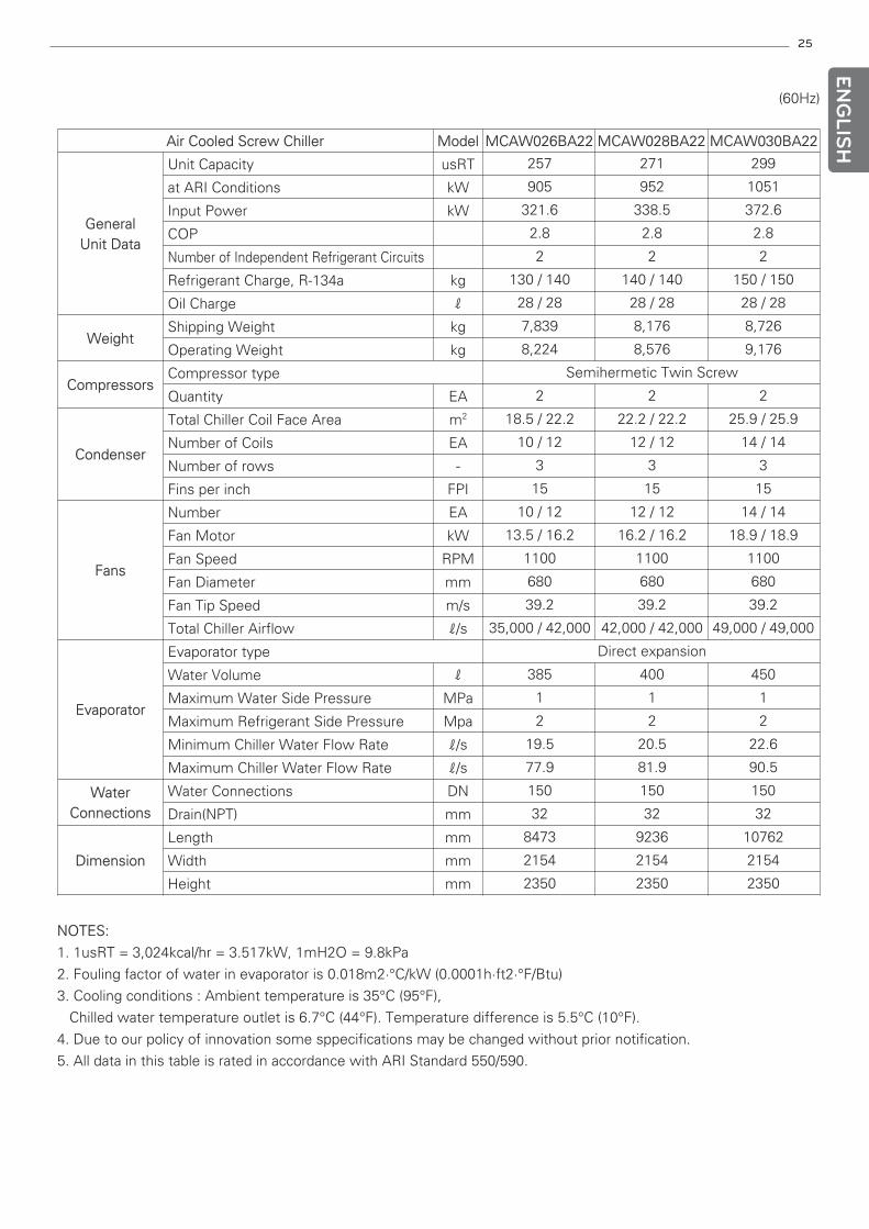
Air Cooled Screw Chiller Model MCAW026BA22 MCAW028BA22 MCAW030BA22
GeneralUnit Data
Unit Capacity usRT
at ARI Conditions kW
Input Power kW
COP
Number of Independent Refrigerant Circuits
Refrigerant Charge, R-134a kg
Oil Charge ℓ
WeightShipping Weight kg
Operating Weight kg
CompressorsCompressor type
Quantity EA
Condenser
Total Chiller Coil Face Area m2
Number of Coils EA
Number of rows -
Fins per inch FPI
Fans
Number EA
Fan Motor kW
Fan Speed RPM
Fan Diameter mm
Fan Tip Speed m/s
Total Chiller Airflow ℓ/s
Evaporator
Evaporator type
Water Volume ℓ
Maximum Water Side Pressure MPa
Maximum Refrigerant Side Pressure Mpa
Minimum Chiller Water Flow Rate ℓ/s
Maximum Chiller Water Flow Rate ℓ/s
WaterConnections
Water Connections DN
Drain(NPT) mm
Dimension
Length mm
Width mm
Height mm
257 271 299
905 952 1051
321.6 338.5 372.6
2.8 2.8 2.8
2 2 2
130 / 140 140 / 140 150 / 150
28 / 28 28 / 28 28 / 28
7,839 8,176 8,726
8,224 8,576 9,176
Semihermetic Twin Screw
2 2 2
18.5 / 22.2 22.2 / 22.2 25.9 / 25.9
10 / 12 12 / 12 14 / 14
3 3 3
15 15 15
10 / 12 12 / 12 14 / 14
13.5 / 16.2 16.2 / 16.2 18.9 / 18.9
1100 1100 1100
680 680 680
39.2 39.2 39.2
35,000 / 42,000 42,000 / 42,000 49,000 / 49,000
Direct expansion
385 400 450
1 1 1
2 2 2
19.5 20.5 22.6
77.9 81.9 90.5
150 150 150
32 32 32
8473 9236 10762
2154 2154 2154
2350 2350 2350
26
ENG
LISH
NOTES:
1. 1usRT = 3,024kcal/hr = 3.517kW, 1mH2O = 9.8kPa
2. Fouling factor of water in evaporator is 0.018m2·°C/kW (0.0001h·ft2·°F/Btu)
3. Cooling conditions : Ambient temperature is 35°C (95°F),
Chilled water temperature outlet is 6.7°C (44°F). Temperature difference is 5.5°C (10°F).
4. Due to our policy of innovation some sppecifications may be changed without prior notification.
5. All data in this table is rated in accordance with ARI Standard 550/590.
(60Hz)
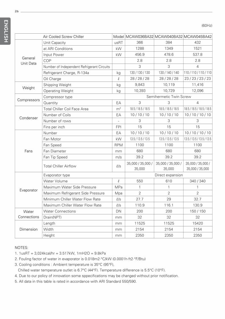
Air Cooled Screw Chiller Model MCAW036BA32 MCAW040BA32 MCAW045BA42
GeneralUnit Data
Unit Capacity usRT
at ARI Conditions kW
Input Power kW
COP
Number of Independent Refrigerant Circuits
Refrigerant Charge, R-134a kg
Oil Charge ℓ
WeightShipping Weight kg
Operating Weight kg
CompressorsCompressor type
Quantity EA
Condenser
Total Chiller Coil Face Area m2
Number of Coils EA
Number of rows -
Fins per inch FPI
Fans
Number EA
Fan Motor kW
Fan Speed RPM
Fan Diameter mm
Fan Tip Speed m/s
Total Chiller Airflow ℓ/s35,000 / 35,000 /
35,00035,000 / 35,000 /
35,00035,000 / 35,000 /35,000 / 35,000
Evaporator
Evaporator type
Water Volume ℓ
Maximum Water Side Pressure MPa
Maximum Refrigerant Side Pressure Mpa
Minimum Chiller Water Flow Rate ℓ/s
Maximum Chiller Water Flow Rate ℓ/s
WaterConnections
Water Connections DN
Drain(NPT) mm
Dimension
Length mm
Width mm
Height mm
366 384 432
1288 1349 1521
456.9 478.6 537.8
2.8 2.8 2.8
3 3 4
130 / 130 / 130 130 / 140 / 140 110 / 110 / 110 / 110
28 / 28 / 28 28 / 28 / 28 23 / 23 / 23 / 23
9,843 10,119 11,416
10,393 10,729 12,096
Semihermetic Twin Screw
3 3 4
18.5 / 18.5 / 18.5 18.5 / 18.5 / 18.5 18.5 / 18.5 / 18.5 / 18.5
10 / 10 / 10 10 / 10 / 10 10 / 10 / 10 / 10
3 3 3
15 15 15
10 / 10 / 10 10 / 10 / 10 10 / 10 / 10 / 10
13.5 / 13.5 / 13.5 13.5 / 13.5 / 13.5 13.5 / 13.5 / 13.5 / 13.5
1100 1100 1100
680 680 680
39.2 39.2 39.2
Direct expansion
550 610 340 / 340
1 1 1
2 2 2
27.7 29 32.7
110.9 116.1 130.9
200 200 150 / 150
32 32 32
11525 11525 15420
2154 2154 2154
2350 2350 2350
27
ENG
LISH
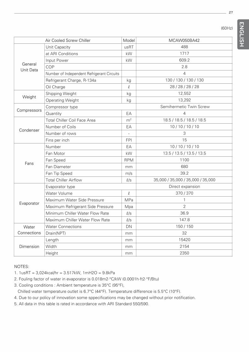
NOTES:
1. 1usRT = 3,024kcal/hr = 3.517kW, 1mH2O = 9.8kPa
2. Fouling factor of water in evaporator is 0.018m2·°C/kW (0.0001h·ft2·°F/Btu)
3. Cooling conditions : Ambient temperature is 35°C (95°F),
Chilled water temperature outlet is 6.7°C (44°F). Temperature difference is 5.5°C (10°F).
4. Due to our policy of innovation some sppecifications may be changed without prior notification.
5. All data in this table is rated in accordance with ARI Standard 550/590.
(60Hz)
Air Cooled Screw Chiller Model MCAW050BA42
GeneralUnit Data
Unit Capacity usRT
at ARI Conditions kW
Input Power kW
COP
Number of Independent Refrigerant Circuits
Refrigerant Charge, R-134a kg
Oil Charge ℓ
WeightShipping Weight kg
Operating Weight kg
CompressorsCompressor type
Quantity EA
Condenser
Total Chiller Coil Face Area m2
Number of Coils EA
Number of rows -
Fins per inch FPI
Fans
Number EA
Fan Motor kW
Fan Speed RPM
Fan Diameter mm
Fan Tip Speed m/s
Total Chiller Airflow ℓ/s
Evaporator
Evaporator type
Water Volume ℓ
Maximum Water Side Pressure MPa
Maximum Refrigerant Side Pressure Mpa
Minimum Chiller Water Flow Rate ℓ/s
Maximum Chiller Water Flow Rate ℓ/s
WaterConnections
Water Connections DN
Drain(NPT) mm
Dimension
Length mm
Width mm
Height mm
488
1717
609.2
2.8
4
130 / 130 / 130 / 130
28 / 28 / 28 / 28
12,552
13,292
Semihermetic Twin Screw
4
18.5 / 18.5 / 18.5 / 18.5
10 / 10 / 10 / 10
3
15
10 / 10 / 10 / 10
13.5 / 13.5 / 13.5 / 13.5
1100
680
39.2
35,000 / 35,000 / 35,000 / 35,000
Direct expansion
370 / 370
1
2
36.9
147.8
150 / 150
32
15420
2154
2350
28
ENG
LISH
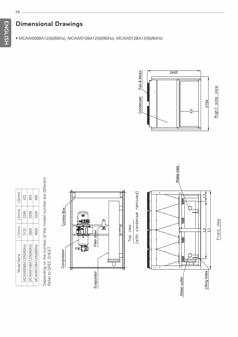
Dimensional Drawings
• MCAW008BA12(50/60Hz), MCAW010BA12(50/60Hz), MCAW012BA12(50/60Hz)D
epen
ding
on
the
num
ber
of t
he m
odel
num
ber
are
diff
eren
t.R
efer
to
SP
EC
SH
EE
T.
Mod
el N
ame
L1(m
m)
L2(m
m)
L3(m
m)
MC
AW
008B
A12
(50/
60H
z)31
3222
8942
2
MC
AW
010B
A12
(50/
60H
z)38
9522
8980
3
MC
AW
012B
A12
(50/
60H
z)46
5833
2866
5
29
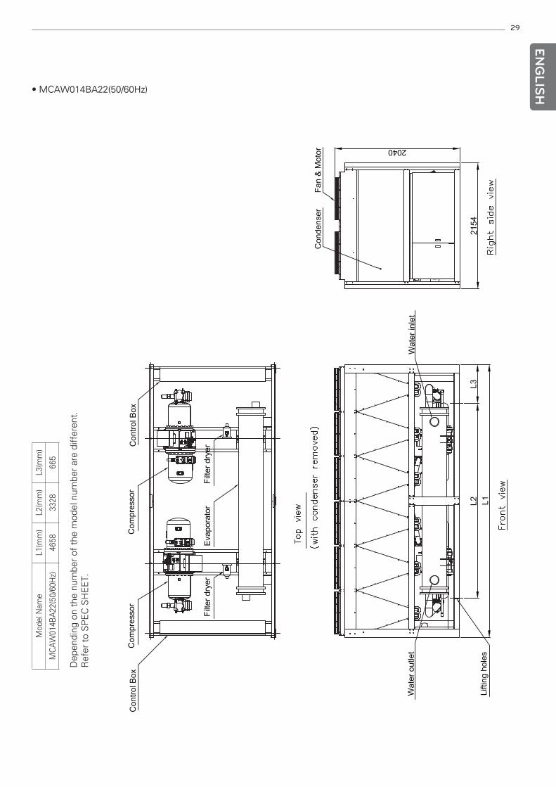
• MCAW014BA22(50/60Hz)
ENG
LISH
Dep
endi
ng o
n th
e nu
mbe
r of
the
mod
el n
umbe
r ar
e di
ffer
ent.
Ref
er t
o S
PE
C S
HE
ET.
Mod
el N
ame
L1(m
m)
L2(m
m)
L3(m
m)
MC
AW
014B
A22
(50/
60H
z)46
5833
2866
5
30
ENG
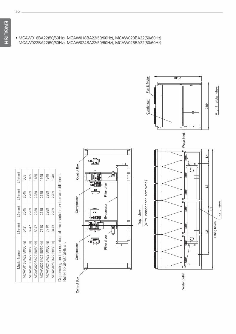
LISH • MCAW016BA22(50/60Hz), MCAW018BA22(50/60Hz), MCAW020BA22(50/60Hz)
MCAW022BA22(50/60Hz), MCAW024BA22(50/60Hz), MCAW026BA22(50/60Hz)
Dep
endi
ng o
n th
e nu
mbe
r of
the
mod
el n
umbe
r ar
e di
ffer
ent.
Ref
er t
o S
PE
C S
HE
ET.
Mod
el N
ame
L1(m
m)
L2(m
m)
L3(m
m)
L4(m
m)
MC
AW
016B
A22
(50/
60H
z)54
2120
4520
4566
5
MC
AW
018B
A22
(50/
60H
z)69
4722
8922
8911
85
MC
AW
020B
A22
(50/
60H
z)69
4722
8922
8911
85
MC
AW
022B
A22
(50/
60H
z)77
1022
8922
8919
48
MC
AW
024B
A22
(50/
60H
z)77
1022
8922
8919
48
MC
AW
026B
A22
(50/
60H
z)84
7322
8922
8919
48
31
ENG
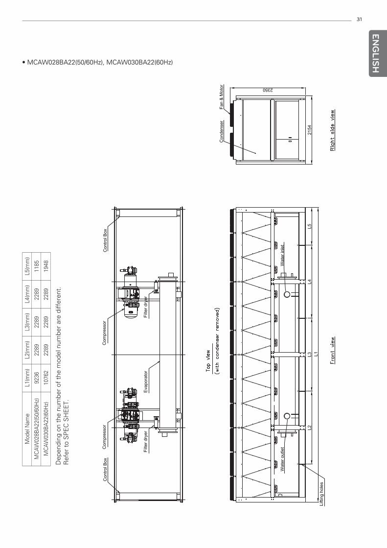
LISH• MCAW028BA22(50/60Hz), MCAW030BA22(60Hz)
Dep
endi
ng o
n th
e nu
mbe
r of
the
mod
el n
umbe
r ar
e di
ffer
ent.
Ref
er t
o S
PE
C S
HE
ET.
Mod
el N
ame
L1(m
m)
L2(m
m)
L3(m
m)
L4(m
m)
L5(m
m)
MC
AW
028B
A22
(50/
60H
z)92
3622
8922
8922
8911
85
MC
AW
030B
A22
(60H
z)10
762
2289
2289
2289
1948
32
ENG
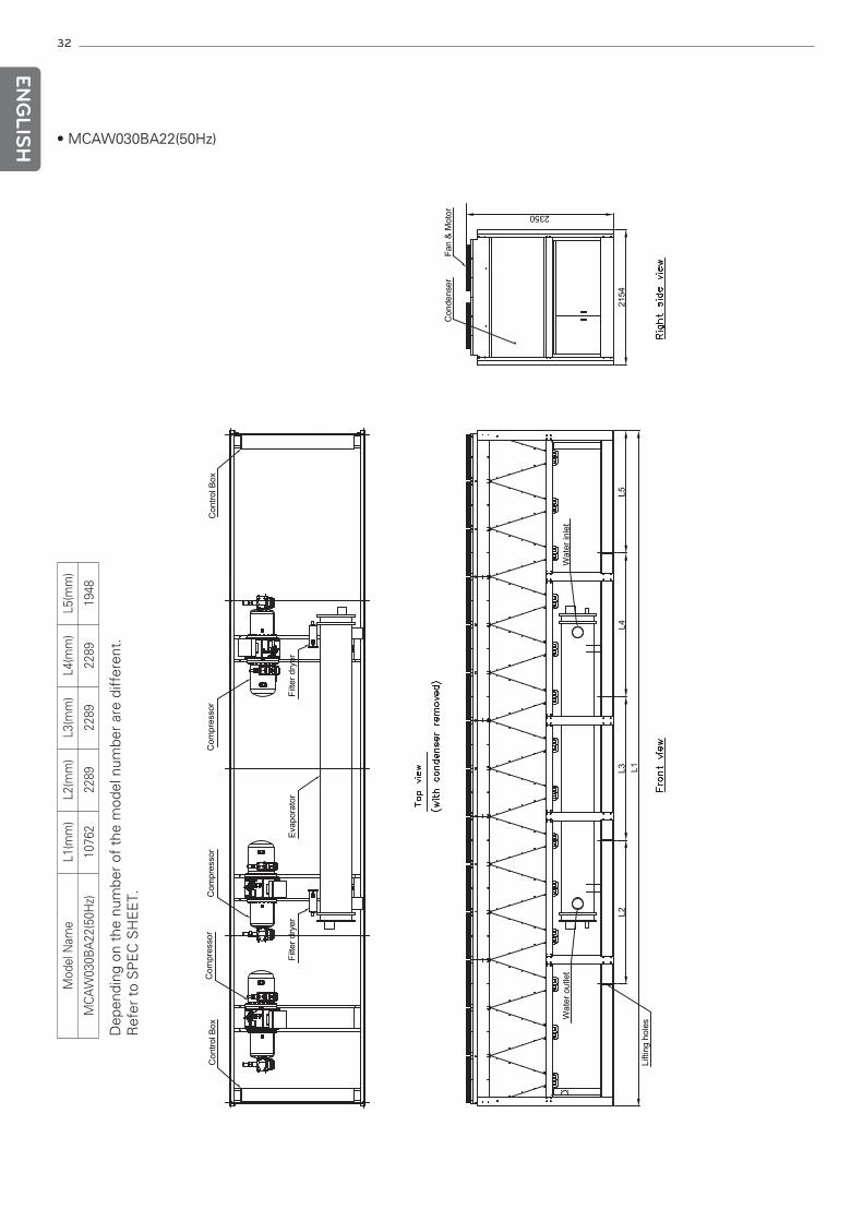
LISH • MCAW030BA22(50Hz)
Dep
endi
ng o
n th
e nu
mbe
r of
the
mod
el n
umbe
r ar
e di
ffer
ent.
Ref
er t
o S
PE
C S
HE
ET.
Mod
el N
ame
L1(m
m)
L2(m
m)
L3(m
m)
L4(m
m)
L5(m
m)
MC
AW
030B
A22
(50H
z)10
762
2289
2289
2289
1948
33
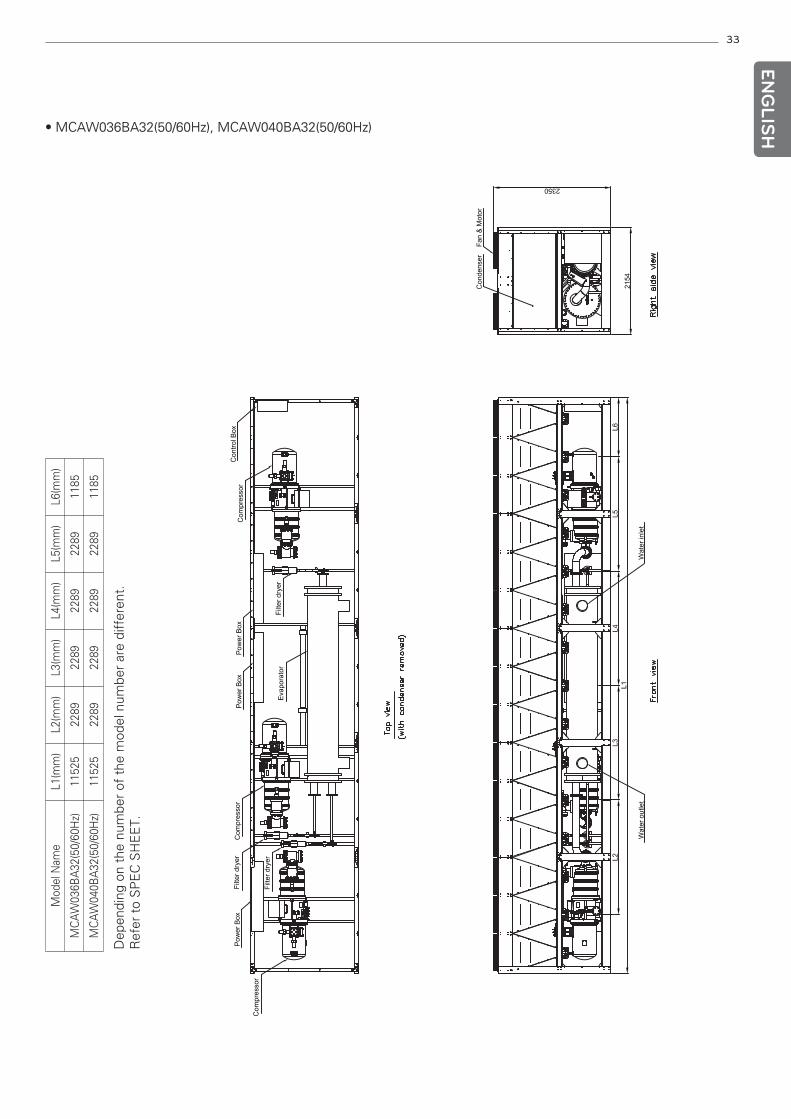
ENG
LISH• MCAW036BA32(50/60Hz), MCAW040BA32(50/60Hz)
Dep
endi
ng o
n th
e nu
mbe
r of
the
mod
el n
umbe
r ar
e di
ffer
ent.
Ref
er t
o S
PE
C S
HE
ET.
Mod
el N
ame
L1(m
m)
L2(m
m)
L3(m
m)
L4(m
m)
L5(m
m)
L6(m
m)
MC
AW
036B
A32
(50/
60H
z)11
525
2289
2289
2289
2289
1185
MC
AW
040B
A32
(50/
60H
z)11
525
2289
2289
2289
2289
1185
34
ENG
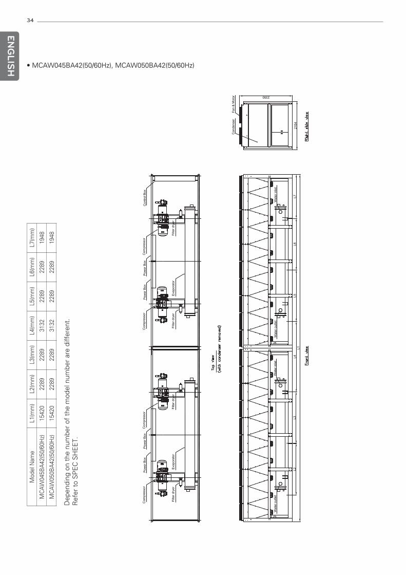
LISH • MCAW045BA42(50/60Hz), MCAW050BA42(50/60Hz)D
epen
ding
on
the
num
ber
of t
he m
odel
num
ber
are
diff
eren
t.R
efer
to
SP
EC
SH
EE
T.
Mod
el N
ame
L1(m
m)
L2(m
m)
L3(m
m)
L4(m
m)
L5(m
m)
L6(m
m)
L7(m
m)
MC
AW
045B
A42
(50/
60H
z)15
420
2289
2289
3132
2289
2289
1948
MC
AW
050B
A42
(50/
60H
z)15
420
2289
2289
3132
2289
2289
1948
35
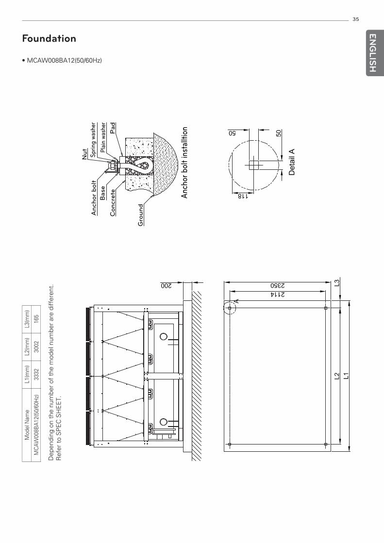
Foundation
• MCAW008BA12(50/60Hz)
Anchor
bolt
Base
Concre
te
Gro
und
Anch
or
bolt
inst
allt
ion
Nut
Sp
ring
was
her
Pla
in w
asher
Pad
Dep
endi
ng o
n th
e nu
mbe
r of
the
mod
el n
umbe
r ar
e di
ffer
ent.
Ref
er t
o S
PE
C S
HE
ET.
Mod
el N
ame
L1(m
m)
L2(m
m)
L3(m
m)
MC
AW
008B
A12
(50/
60H
z)33
3230
0216
5
ENG
LISH
36
ENG
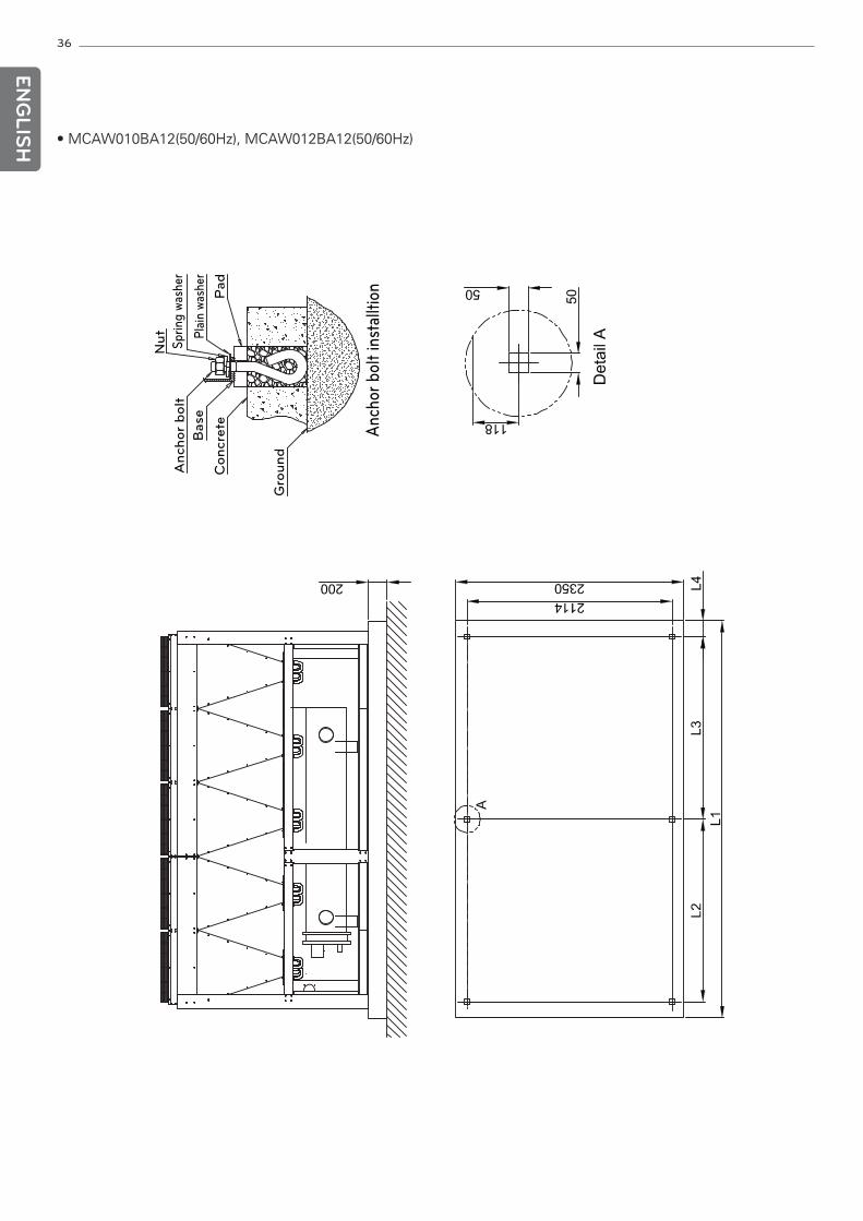
LISH • MCAW010BA12(50/60Hz), MCAW012BA12(50/60Hz)
Anchor
bolt
Base
Concre
te
Gro
und
Anch
or
bolt
inst
allt
ion
Nut
Sp
ring
was
her
Pla
in w
asher
Pad
37
ENG
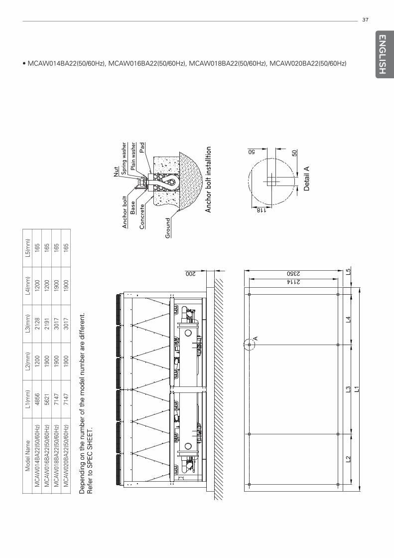
LISH• MCAW014BA22(50/60Hz), MCAW016BA22(50/60Hz), MCAW018BA22(50/60Hz), MCAW020BA22(50/60Hz)
Anchor
bolt
Base
Concre
te
Gro
und
Anch
or
bolt
inst
allt
ion
Nut
Sp
ring
was
her
Pla
in w
asher
Pad
Dep
endi
ng o
n th
e nu
mbe
r of
the
mod
el n
umbe
r ar
e di
ffer
ent.
Ref
er t
o S
PE
C S
HE
ET.
Mod
el N
ame
L1(m
m)
L2(m
m)
L3(m
m)
L4(m
m)
L5(m
m)
MC
AW
014B
A22
(50/
60H
z)48
5612
0021
2812
0016
5
MC
AW
016B
A22
(50/
60H
z)56
2119
0021
9112
0016
5
MC
AW
018B
A22
(50/
60H
z)71
4719
0030
1719
0016
5
MC
AW
020B
A22
(50/
60H
z)71
4719
0030
1719
0016
5
38
ENG
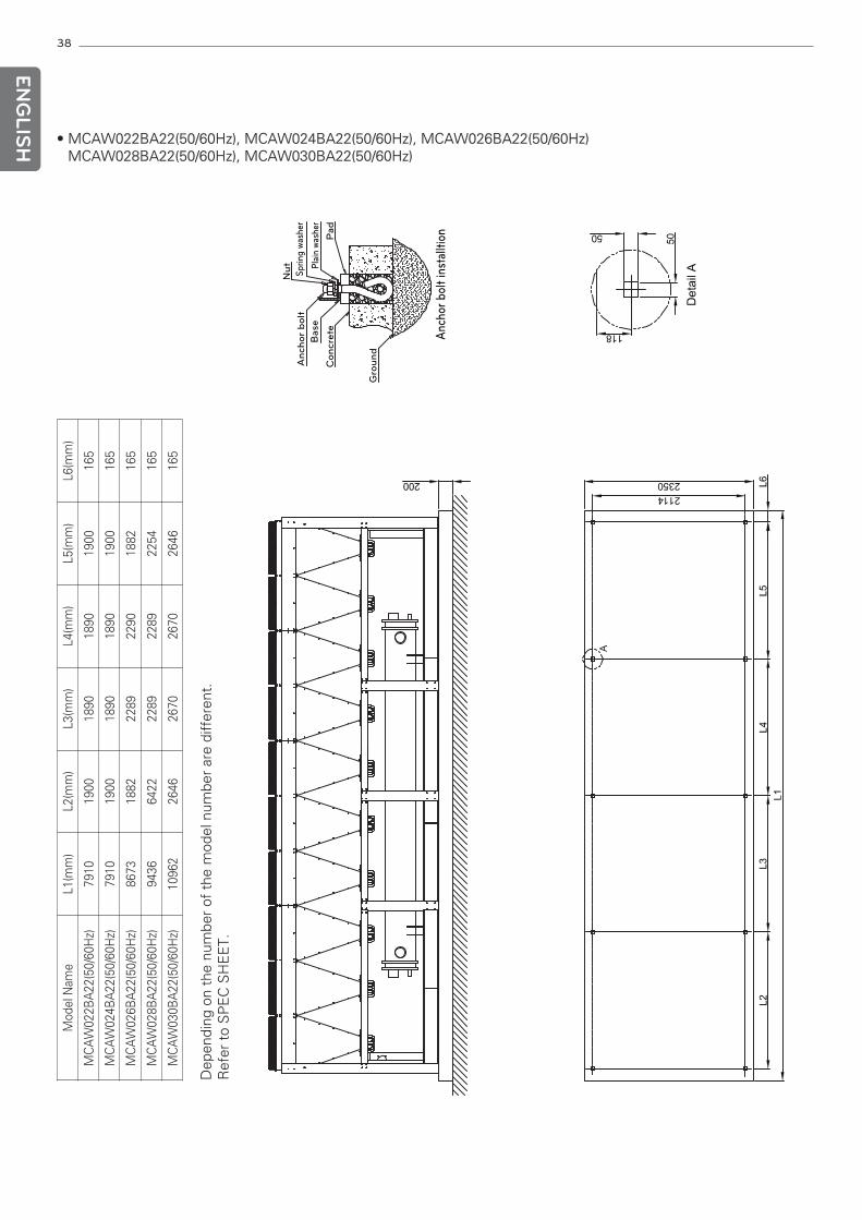
LISH • MCAW022BA22(50/60Hz), MCAW024BA22(50/60Hz), MCAW026BA22(50/60Hz)
MCAW028BA22(50/60Hz), MCAW030BA22(50/60Hz)
Anchor
bolt
Base
Concre
te
Gro
und
Anch
or
bolt
inst
allt
ion
Nut
Sp
ring
was
her
Pla
in w
asher
Pad
Dep
endi
ng o
n th
e nu
mbe
r of
the
mod
el n
umbe
r ar
e di
ffer
ent.
Ref
er t
o S
PE
C S
HE
ET.
Mod
el N
ame
L1(m
m)
L2(m
m)
L3(m
m)
L4(m
m)
L5(m
m)
L6(m
m)
MC
AW
022B
A22
(50/
60H
z)79
1019
0018
9018
9019
0016
5
MC
AW
024B
A22
(50/
60H
z)79
1019
0018
9018
9019
0016
5
MC
AW
026B
A22
(50/
60H
z)86
7318
8222
8922
9018
8216
5
MC
AW
028B
A22
(50/
60H
z)94
3664
2222
8922
8922
5416
5
MC
AW
030B
A22
(50/
60H
z)10
962
2646
2670
2670
2646
165
39
ENG
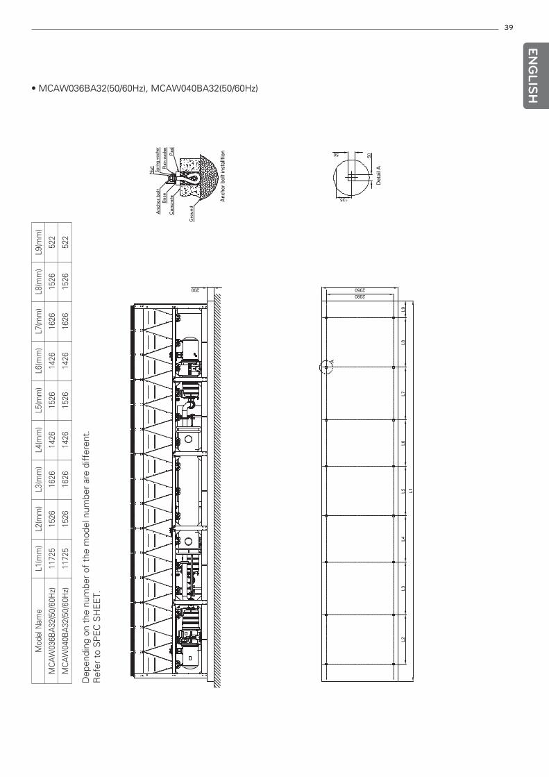
LISH• MCAW036BA32(50/60Hz), MCAW040BA32(50/60Hz)
Anchor
bolt
Base
Concre
te
Gro
und
Anch
or
bolt
inst
allt
ion
Nut
Sp
ring
was
her
Pla
in w
asher
Pad
Dep
endi
ng o
n th
e nu
mbe
r of
the
mod
el n
umbe
r ar
e di
ffer
ent.
Ref
er t
o S
PE
C S
HE
ET.
Mod
el N
ame
L1(m
m)
L2(m
m)
L3(m
m)
L4(m
m)
L5(m
m)
L6(m
m)
L7(m
m)
L8(m
m)
L9(m
m)
MC
AW
036B
A32
(50/
60H
z)11
725
1526
1626
1426
1526
1426
1626
1526
522
MC
AW
040B
A32
(50/
60H
z)11
725
1526
1626
1426
1526
1426
1626
1526
522
40
ENG
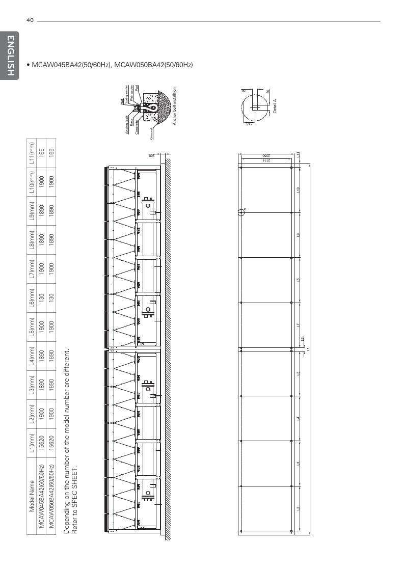
LISH • MCAW045BA42(50/60Hz), MCAW050BA42(50/60Hz)
Anchor
bolt
Base
Concre
te
Gro
und
Anch
or
bolt
inst
allt
ion
Nut
Sp
ring
was
her
Pla
in w
asher
Pad
Mod
el N
ame
L1(m
m)
L2(m
m)
L3(m
m)
L4(m
m)
L5(m
m)
L6(m
m)
L7(m
m)
L8(m
m)
L9(m
m)
L10(
mm
)L1
1(m
m)
MC
AW
045B
A42
(60/
50H
z)15
620
1900
1890
1890
1900
130
1900
1890
1890
1900
165
MC
AW
050B
A42
(60/
50H
z)15
620
1900
1890
1890
1900
130
1900
1890
1890
1900
165
Dep
endi
ng o
n th
e nu
mbe
r of
the
mod
el n
umbe
r ar
e di
ffer
ent.
Ref
er t
o S
PE
C S
HE
ET.
41
ENG
LISH
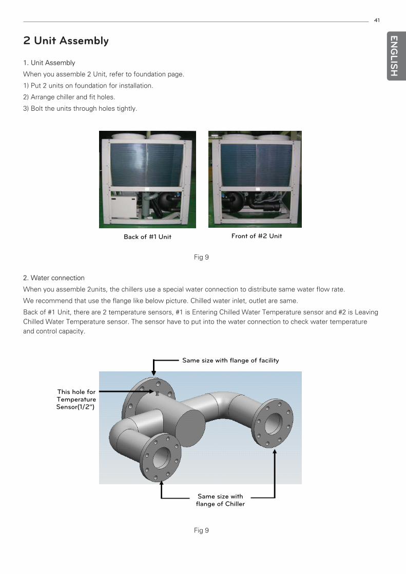
2 Unit Assembly
1. Unit Assembly
When you assemble 2 Unit, refer to foundation page.
1) Put 2 units on foundation for installation.
2) Arrange chiller and fit holes.
3) Bolt the units through holes tightly.
2. Water connection
When you assemble 2units, the chillers use a special water connection to distribute same water flow rate.
We recommend that use the flange like below picture. Chilled water inlet, outlet are same.
Back of #1 Unit, there are 2 temperature sensors, #1 is Entering Chilled Water Temperature sensor and #2 is LeavingChilled Water Temperature sensor. The sensor have to put into the water connection to check water temperatureand control capacity.
Front of #2 UnitBack of #1 Unit
Same size with
flange of Chiller
Same size with flange of facility
This hole for
Temperature
Sensor(1/2")
Fig 9
Fig 9
42
ENG
LISH
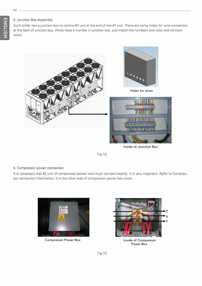
3. Junction Box Assembly
2unit chiller has a junction box to control #2 unit at the end of the #1 unit. There are some holes for wire connectionat the back of junction box. Wires have a number in junction box, just match the numbers and color and connectwires.
4. Compressor power connection
It is necessary that #2 unit of compressor power wire must connect exactly. It is very important. Refer to Compres-sor connection information. It is the other side of compressor power box cover.
Inside of Junction Box
Holes for wires
Compressor Power Box Inside of Compressor
Power Box
Z
X
Y
Fig 10
Fig 10
43
ENG
LISH
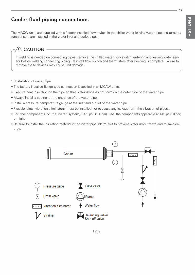
Cooler fluid piping connections
The MACW units are supplied with a factory-installed flow switch in the chiller water leaving water pipe and tempera-ture sensors are installed in the water inlet and outlet pipes.
! CAUTION
If welding is needed on connecting pipes, remove the chilled water flow switch, entering and leaving water sen-sor before welding connecting piping. Reinstall flow switch and thermistors after welding is complete. Failure toremove these devices may cause unit damage.
1. Installation of water pipe
• The factory-installed flange type connection is applied in all MCAW units.
• Execute heat insulation on the pipe so that water drops do not form on the outer side of the water pipe.
• Always install a strainer at the entrance of the water pipe.
• Install a pressure, temperature gauge at the inlet and out let of the water pipe.
• Flexible joints (vibration eliminators) must be installed not to cause any leakage form the vibration of pipes.
• For the components of the water system, 145 psi (10 bar) use the components applicable at 145 psi(10 bar)or higher.
• Be sure to install the insulation material in the water pipe inlet/outlet to prevent water drop, freeze and to save en-ergy.
Fig 9
44
ENG
LISH
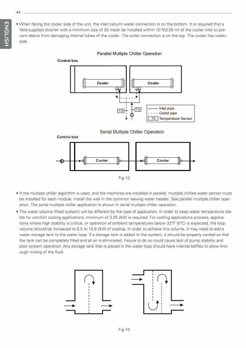
• If the multiple chiller algorithm is used, and the machines are installed in parallel, multiple chilled water sensor mustbe installed for each module. Install the well in the common leaving water header. See parallel multiple chiller oper-ation. The serial multiple chiller application is shown in serial multiple chiller operation.
• The water volume (filled system) will be different by the type of application. In order to keep water temperature sta-ble for comfort cooling applications, minimum of 3.25 l/kW is required. For cooling applications process, applica-tions where high stability is critical, or operation at ambient temperatures below 32°F (0°C) is expected, the loopvolume should be increased to 6.5 to 10.8 l/kW of cooling. In order to achieve this volume, it may need to add awater storage tank to the water loop. If a storage tank is added to the system, it should be properly vented so thatthe tank can be completely filled and all air is eliminated. Failure to do so could cause lack of pump stability andpoor system operation. Any storage tank that is placed in the water loop should have internal baffles to allow thor-ough mixing of the fluid.
• When facing the cooler side of the unit, the inlet (return) water connection is on the bottom. It is required that afield-supplied strainer with a minimum size of 20 mesh be installed within 10 ft(3.05 m) of the cooler inlet to pre-vent debris from damaging internal tubes of the cooler. The outer connection is on the top. The cooler has water-side.
Fig 10
Fig 10
45
ENG
LISH
4. Preparation for year-round operation
In areas where the piping or unit is exposed to 32°F (0°C) or lower ambient temperatures, freeze-up protection is re-quired. If there is no freeze-up protection, water in system (in chiller and all pipes) must be drained out.
2. Cooler pump control
• It is recommended that cooler pump control be utilized on all chillers unless the chilled water pump runs continu-ously or the chilled water system contains a suitable antifreeze solution.
• Refer the control and power wiring schematic for proper connection of the cooler pump output. The cooler pumpoutput will remain energized for 10 minutes, after all compressors stop due to an OFF command. The cooler pumpoutput is also energized anytime a compressor is started.
3. Water treatment
Untreated or improperly treated water may result in corrosion, scaling, erosion, or algae. The services of a qualifiedwater treatment specialist should be obtained to develop and monitor a treatment program.
! CAUTION
Water must be within design flow limits, clean, and treated to ensure proper chiller performance and reduce thepotential of tube damage due to corrosion, scaling, erosion, and algae. LG assumes no responsibility for chillerdamage resulting from untreated or improperly treated water.
• The system must be constructed with pressure tight components and thoroughly tested for installation leaks.
• Installation of water systems should follow sound engineering practice as well as applicable local and industry stan-dards. Improperly designed or installed systems may cause unsatisfactory operation and/or system failure.
• Consult a water treatment specialist or appropriate literature for information regarding filtration, water treatment,and control devices.
• For proper system operation, it is essential that water loops be installed with proper means to manage air in thesystem. Free air in the system can cause noise, reduce terminal output, stop flow, or even cause pump failure dueto pump cavitation. For closed system, equipment should be provided to eliminate all air form the system.
• Install automatic air vents at all high points in the system. Automatic vents should be located in accessible loca-tions for maintenance purposes and protected form freezing.
• Install an air separator in the water loop, at the place where the water is at higher temperatures and lower pres-sure – usually in the chilled water return piping.
46
ENG
LISH
Filled chilled water loop
Before starting unit, be sure all of the air has been purged from the system.
The maximum cooler fluid side pressure is 145 psig (10 bar). Check the pressure rating for all of the chilled water de-vices installed. Do not exceed the lowest pressure rated device.
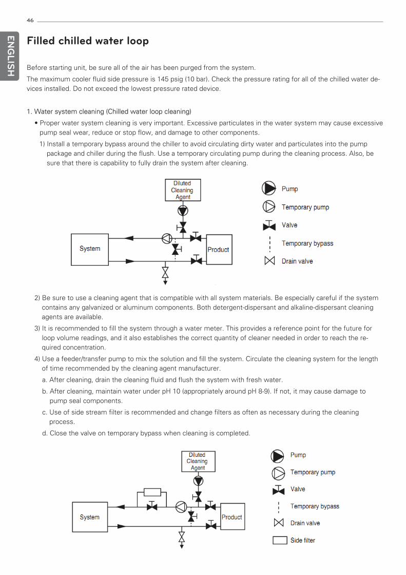
1. Water system cleaning (Chilled water loop cleaning)
• Proper water system cleaning is very important. Excessive particulates in the water system may cause excessivepump seal wear, reduce or stop flow, and damage to other components.
1) Install a temporary bypass around the chiller to avoid circulating dirty water and particulates into the pumppackage and chiller during the flush. Use a temporary circulating pump during the cleaning process. Also, besure that there is capability to fully drain the system after cleaning.
2) Be sure to use a cleaning agent that is compatible with all system materials. Be especially careful if the systemcontains any galvanized or aluminum components. Both detergent-dispersant and alkaline-dispersant cleaningagents are available.
3) It is recommended to fill the system through a water meter. This provides a reference point for the future forloop volume readings, and it also establishes the correct quantity of cleaner needed in order to reach the re-quired concentration.
4) Use a feeder/transfer pump to mix the solution and fill the system. Circulate the cleaning system for the lengthof time recommended by the cleaning agent manufacturer.
a. After cleaning, drain the cleaning fluid and flush the system with fresh water.
b. After cleaning, maintain water under pH 10 (appropriately around pH 8-9). If not, it may cause damage topump seal components.
c. Use of side stream filter is recommended and change filters as often as necessary during the cleaningprocess.
d. Close the valve on temporary bypass when cleaning is completed.
47
ENG
LISH
• Normally, a closed system needs to be filled only once. The actual filling process is a fairly simple procedure. Allair should be purged or vented from the system. Thorough venting at high points and circulation at room temper-ature for several hours is highly recommended.
• It is ideal to clean up the loop before connecting the equipment. The strainer must be removed and changedwithin the first 24 hours of operation.
2. Water treatment
• Fill the fluid loop with water (or brine) and a corrosion-resistant inhibitor suitable for the water of that area.
• Consult the local water treatment specialist for characteristics of system water and a recommended inhibitor forthe cooler fluid loop.
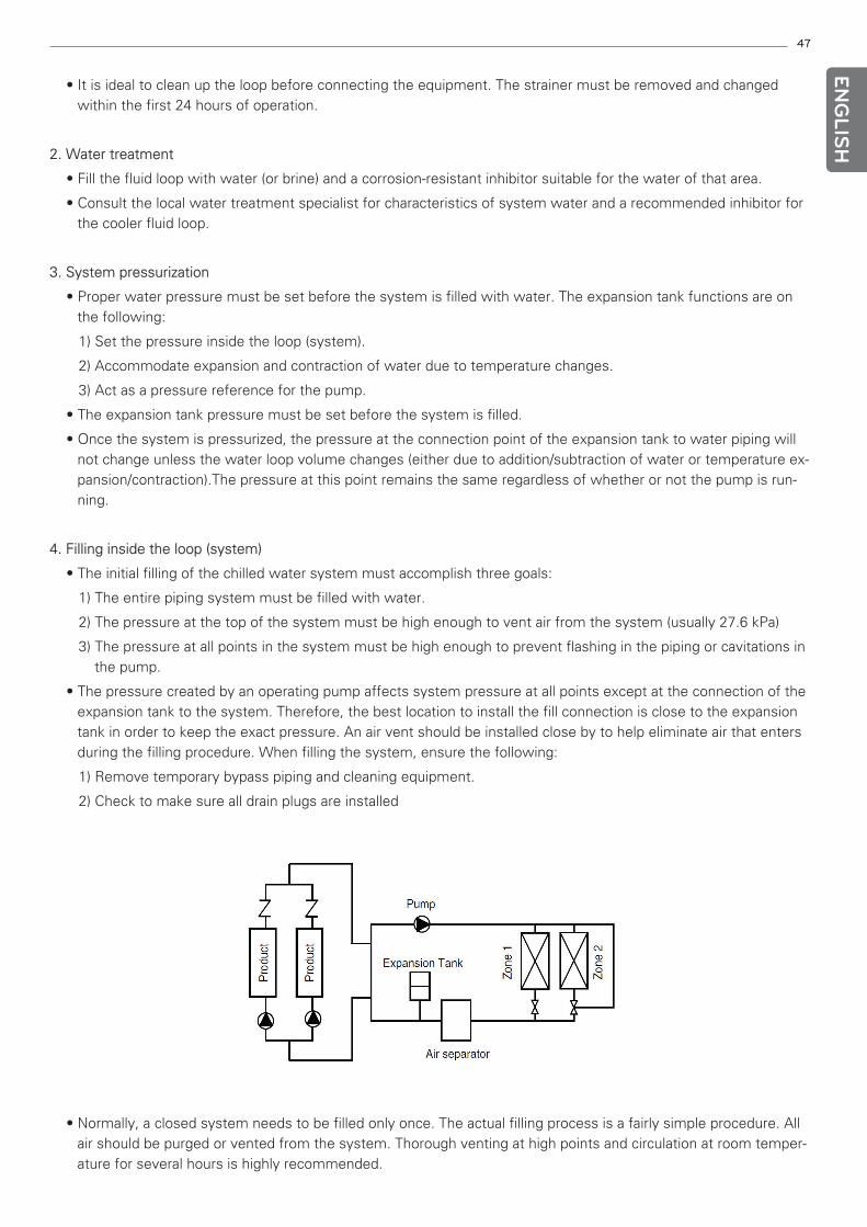
3. System pressurization
• Proper water pressure must be set before the system is filled with water. The expansion tank functions are onthe following:
1) Set the pressure inside the loop (system).
2) Accommodate expansion and contraction of water due to temperature changes.
3) Act as a pressure reference for the pump.
• The expansion tank pressure must be set before the system is filled.
• Once the system is pressurized, the pressure at the connection point of the expansion tank to water piping willnot change unless the water loop volume changes (either due to addition/subtraction of water or temperature ex-pansion/contraction).The pressure at this point remains the same regardless of whether or not the pump is run-ning.
4. Filling inside the loop (system)
• The initial filling of the chilled water system must accomplish three goals:
1) The entire piping system must be filled with water.
2) The pressure at the top of the system must be high enough to vent air from the system (usually 27.6 kPa)
3) The pressure at all points in the system must be high enough to prevent flashing in the piping or cavitations inthe pump.
• The pressure created by an operating pump affects system pressure at all points except at the connection of theexpansion tank to the system. Therefore, the best location to install the fill connection is close to the expansiontank in order to keep the exact pressure. An air vent should be installed close by to help eliminate air that entersduring the filling procedure. When filling the system, ensure the following:
1) Remove temporary bypass piping and cleaning equipment.
2) Check to make sure all drain plugs are installed
48
ENG
LISH
5. Set water flow rate
• Once the system is cleaned, pressurized, and filled, the flow rate through the chiller needs to be established. Se-lect the motor and determine the balancing valve in order to meet the Maximum Water side pressure and theMinimum chiller water flow rate of the specification.
• We recommend a differential pressure gauge when measuring pressure across the pumps or balancing valves.This provides for greater accuracy and reduces error build-up that often occurs when subtracting pressure madeby different gauges.
6. Pump modification for flow setting
• The loss of pressure inside of the loop must be minimized in order to increase flow rate. If greater flow is neces-sary, consider opening the valve. Also, verify that the strainer is clean, and that no unnecessary system resist-ance is present, such as partially closed isolation valves.
• Once the combination valve is set, note the stem position. If later service work requires the valve to be closed, itwill be easier to re-balance the system, if the original balance point is known.
• Increasing system resistance by closing the valve will result in less flow. Although it will reduce power consump-tion slightly, it may not be the desirable method of reducing the flow, especially if a large reduction is needed.
7. Freeze protection
• The flow switch will be attached to the product and provided to protect against freezing situations that may occurwhen there is no water flow. When the water temperature falls below the freezing mark, the chiller can be pro-tected by temperature sensor for freezing protection. However, the chiller can’t be protected when there ispower failure and water temperature falls below the freezing mark suddenly. So, you may consider using ethyl-ene glycol or other suitable inhibited anti-freeze solution for chiller protection. Especially you should considerusing inhibited anti-freeze solution or heater when the ambient temperatures are expected to fall below32°F(0°C). Consult local water treatment specialist on characteristics of the system water and add a recom-mended inhibitor to the chilled water. The LG warranty does not cover damage due to freezing. If the abovepropylene or ethylene glycol or other suitable inhibited antifreeze solution is applied, all components such aspump and valve should be usable at the above solutions.
• Do not use unapproved antifreeze solution. Only use appropriately inhibited antifreeze solution which is concen-trated to provide adequate protection for the temperature considered.
8. Preparation for winter shutdown
• If the chiller is not operational during the winter, complete the steps at the end of summer season.
1) We strongly recommend you to drain the water from inside of the loop. You must drain the water from theloop especially when the whole loop or ambient temperature around chiller is below 32°F(0° C).
2) Isolate the cooler from the loop with shutoff valves.
3) Change the drain plug and fill the cooler with water, inhibited antifreeze solution and inhibitor such as propy-lene glycol.
4) Leave the cooler filled with the antifreeze solution for the winter, or drain if desired.
! CAUTION
Protection device must be installed in order to protect contamination of the public water supply. The protectiondevice is very important, especially when the inhibited antifreeze is used.
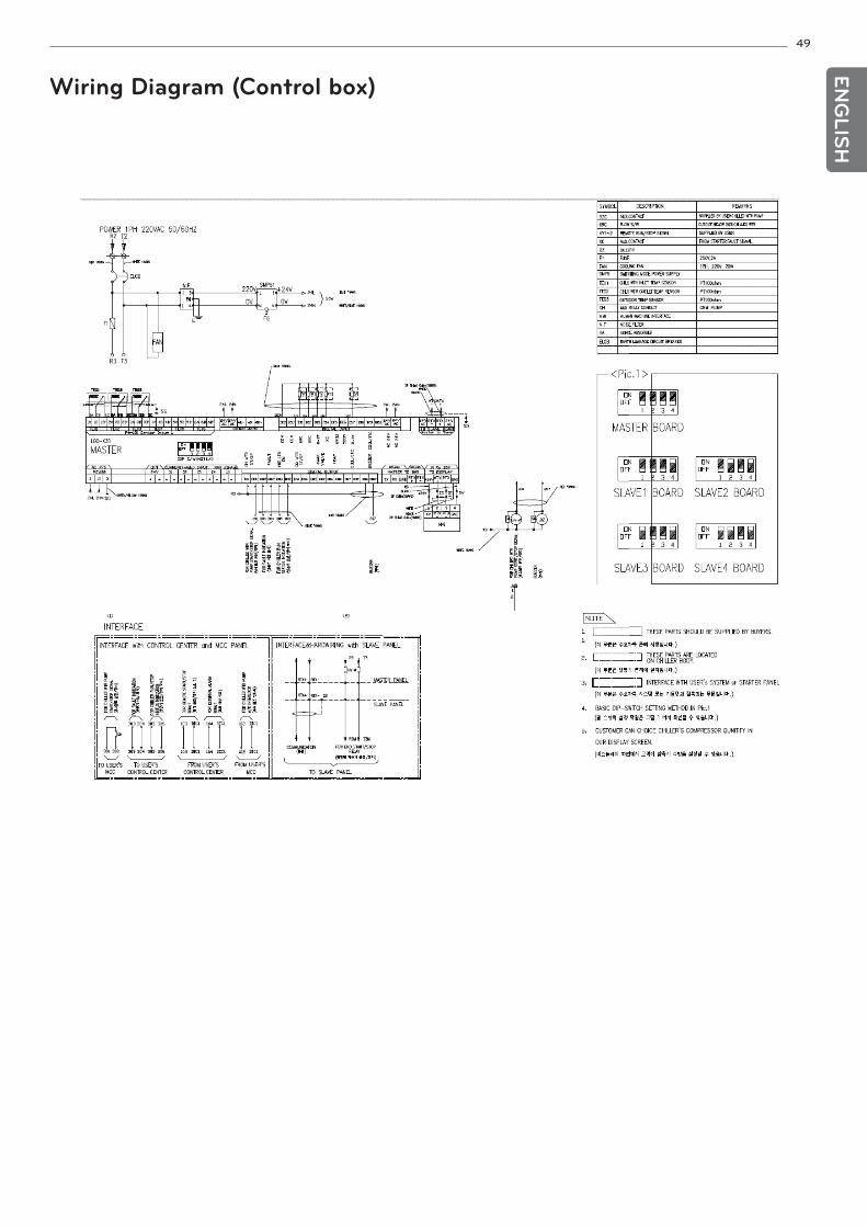
49
ENG
LISH
Wiring Diagram (Control box)
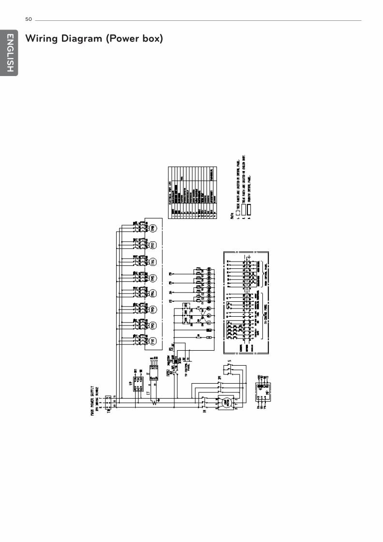
50
ENG
LISH
Wiring Diagram (Power box)
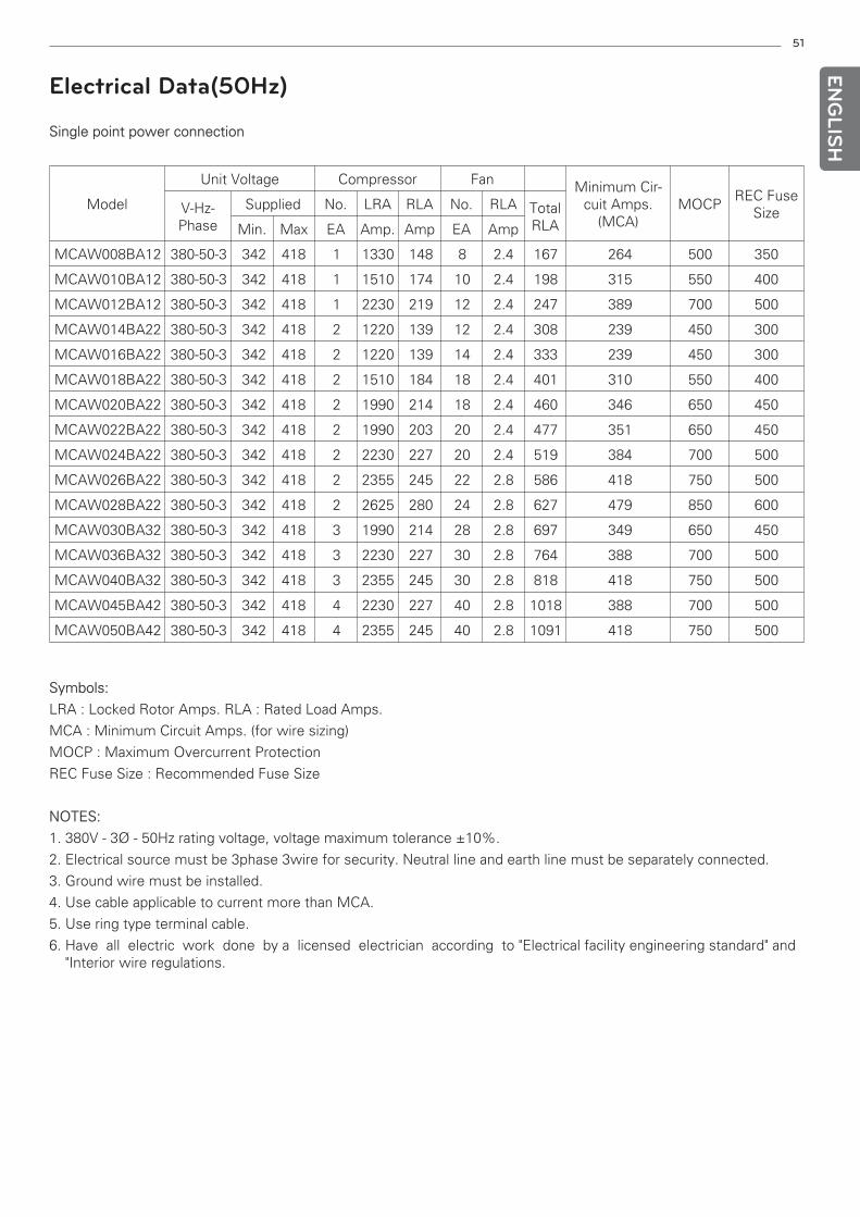
51
ENG
LISH
Electrical Data(50Hz)
Single point power connection
Model
Unit Voltage Compressor Fan Minimum Cir-cuit Amps.
(MCA)MOCP
REC FuseSizeV-Hz-
Phase
Supplied No. LRA RLA No. RLA TotalRLAMin. Max EA Amp. Amp EA Amp
Symbols:
LRA : Locked Rotor Amps. RLA : Rated Load Amps.
MCA : Minimum Circuit Amps. (for wire sizing)
MOCP : Maximum Overcurrent Protection
REC Fuse Size : Recommended Fuse Size
NOTES:
1. 380V - 3Ø - 50Hz rating voltage, voltage maximum tolerance ±10%.
2. Electrical source must be 3phase 3wire for security. Neutral line and earth line must be separately connected.
3. Ground wire must be installed.
4. Use cable applicable to current more than MCA.
5. Use ring type terminal cable.
6. Have all electric work done by a licensed electrician according to "Electrical facility engineering standard" and"Interior wire regulations.
MCAW008BA12 380-50-3 342 418 1 1330 148 8 2.4 167 264 500 350
MCAW010BA12 380-50-3 342 418 1 1510 174 10 2.4 198 315 550 400
MCAW012BA12 380-50-3 342 418 1 2230 219 12 2.4 247 389 700 500
MCAW014BA22 380-50-3 342 418 2 1220 139 12 2.4 308 239 450 300
MCAW016BA22 380-50-3 342 418 2 1220 139 14 2.4 333 239 450 300
MCAW018BA22 380-50-3 342 418 2 1510 184 18 2.4 401 310 550 400
MCAW020BA22 380-50-3 342 418 2 1990 214 18 2.4 460 346 650 450
MCAW022BA22 380-50-3 342 418 2 1990 203 20 2.4 477 351 650 450
MCAW024BA22 380-50-3 342 418 2 2230 227 20 2.4 519 384 700 500
MCAW026BA22 380-50-3 342 418 2 2355 245 22 2.8 586 418 750 500
MCAW028BA22 380-50-3 342 418 2 2625 280 24 2.8 627 479 850 600
MCAW030BA32 380-50-3 342 418 3 1990 214 28 2.8 697 349 650 450
MCAW036BA32 380-50-3 342 418 3 2230 227 30 2.8 764 388 700 500
MCAW040BA32 380-50-3 342 418 3 2355 245 30 2.8 818 418 750 500
MCAW045BA42 380-50-3 342 418 4 2230 227 40 2.8 1018 388 700 500
MCAW050BA42 380-50-3 342 418 4 2355 245 40 2.8 1091 418 750 500
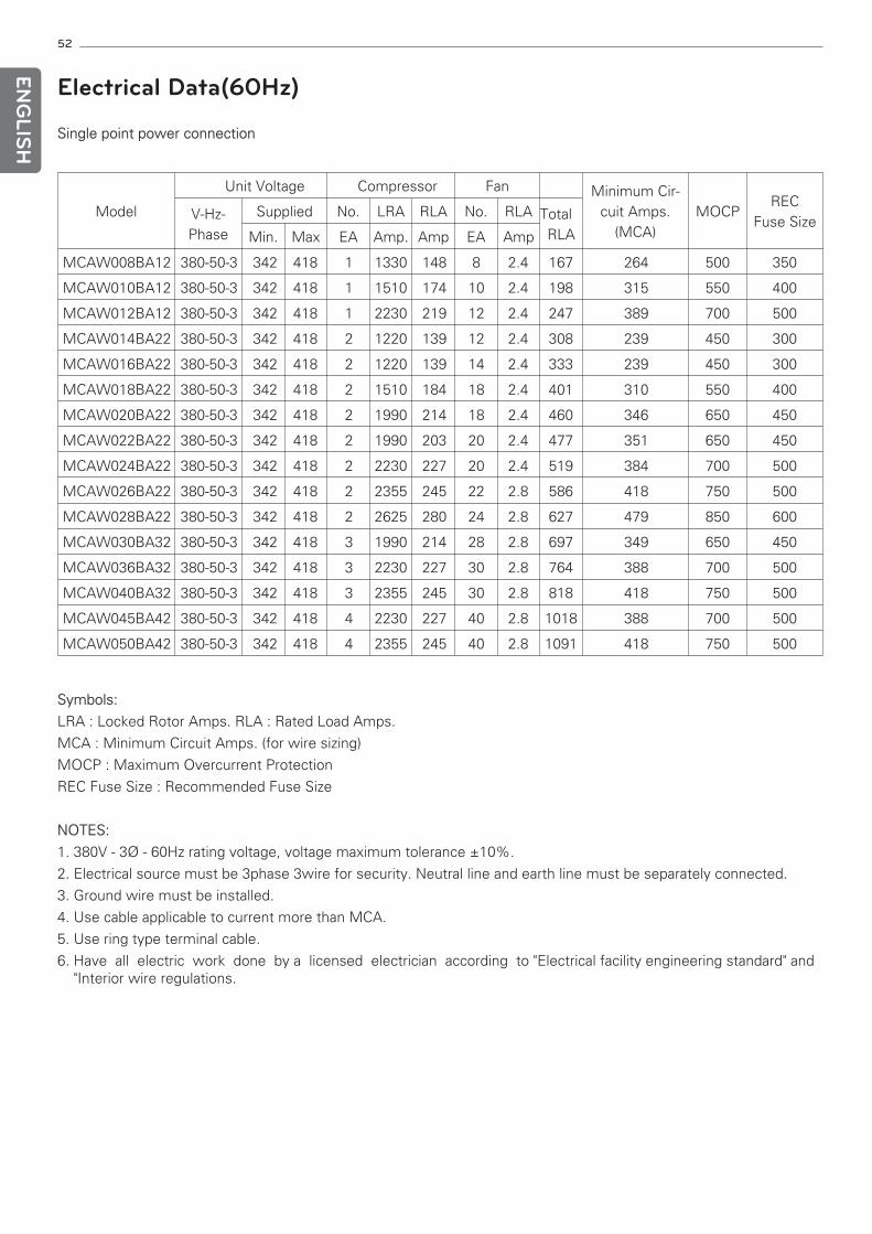
52
ENG
LISH
Electrical Data(60Hz)
Single point power connection
Symbols:
LRA : Locked Rotor Amps. RLA : Rated Load Amps.
MCA : Minimum Circuit Amps. (for wire sizing)
MOCP : Maximum Overcurrent Protection
REC Fuse Size : Recommended Fuse Size
NOTES:
1. 380V - 3Ø - 60Hz rating voltage, voltage maximum tolerance ±10%.
2. Electrical source must be 3phase 3wire for security. Neutral line and earth line must be separately connected.
3. Ground wire must be installed.
4. Use cable applicable to current more than MCA.
5. Use ring type terminal cable.
6. Have all electric work done by a licensed electrician according to "Electrical facility engineering standard" and"Interior wire regulations.
Model
Unit Voltage Compressor Fan Minimum Cir-cuit Amps.
(MCA)MOCP
REC Fuse SizeV-Hz-
Phase
Supplied No. LRA RLA No. RLA Total RLAMin. Max EA Amp. Amp EA Amp
MCAW008BA12 380-50-3 342 418 1 1330 148 8 2.4 167 264 500 350
MCAW010BA12 380-50-3 342 418 1 1510 174 10 2.4 198 315 550 400
MCAW012BA12 380-50-3 342 418 1 2230 219 12 2.4 247 389 700 500
MCAW014BA22 380-50-3 342 418 2 1220 139 12 2.4 308 239 450 300
MCAW016BA22 380-50-3 342 418 2 1220 139 14 2.4 333 239 450 300
MCAW018BA22 380-50-3 342 418 2 1510 184 18 2.4 401 310 550 400
MCAW020BA22 380-50-3 342 418 2 1990 214 18 2.4 460 346 650 450
MCAW022BA22 380-50-3 342 418 2 1990 203 20 2.4 477 351 650 450
MCAW024BA22 380-50-3 342 418 2 2230 227 20 2.4 519 384 700 500
MCAW026BA22 380-50-3 342 418 2 2355 245 22 2.8 586 418 750 500
MCAW028BA22 380-50-3 342 418 2 2625 280 24 2.8 627 479 850 600
MCAW030BA32 380-50-3 342 418 3 1990 214 28 2.8 697 349 650 450
MCAW036BA32 380-50-3 342 418 3 2230 227 30 2.8 764 388 700 500
MCAW040BA32 380-50-3 342 418 3 2355 245 30 2.8 818 418 750 500
MCAW045BA42 380-50-3 342 418 4 2230 227 40 2.8 1018 388 700 500
MCAW050BA42 380-50-3 342 418 4 2355 245 40 2.8 1091 418 750 500
Electrical Connections
1. Power supply
The electrical characteristics of the available power supply must be same with the equipment nameplate.
Supply voltage must be within the limits indicated.
2. Field power connections and Power wiring
All power wiring must comply with applicable local and national codes. See diagram of power wiring.
3. General Wiring Notes
1) The control circuit does NOT require a separate power source. A step-down transformer from the main three-phase power supply obtains control circuit power. Be sure that the appropriate connection tap is connected onall transformers for the supply voltage. Up to two terminal blocks are provided for field-wired control devices.
2) Cooler and pump heaters (if factory installed) are wired in the control circuit so they are operable as long as themain power supply to the unit is ON. A factory-installed and set overload device protects them.
3) Power entry depends on the size and power entry option ordered.
4) Terminals for field power supply are suitable for copper conductors. Insulation must be rated 75 C minimum.
• The field-supplied disconnect should never be off except when unit is being serviced or is to be down for aprolonged period, in which case the cooler should be drained.
• To ensure power to the heaters, make sure power to the unit is always on (except during service or a pro-longed shutdown).
4. Control power
• Control power is obtained from the main power supply and does not require a separate source
! CAUTION
Electrical shock can cause personal injury and death. Shut off all power to this equipment during installation.There may more than one disconnect switch. Tag all disconnect locations to alert others not to restore poweruntil work is completed.
53
ENG
LISH
54
ENG
LISH
Standard and Options
1. Standard
1) Wye-Delta Compressor starter
2) Discharge line shut off valve - Installed on the discharge port of the compressor.
3) Suction line shut off valve - Suction shut off valve installed on the suction port of the compressor to facilitatemaintenance.
4) Flow Switch-Supplied separately to be wired and installed on the evaporator water piping.
2. Options
1) Condenser - High ambient operation : 125 °F(52 °C)
2) Evaporator - Low leaving temperature : Less than 40 °F(4 °C)
3) Electric and Control
- Circuit breaker
- Unit-mounted non-fused disconnect switch with circuit breaker
4) Etc. - Compressor sound attenuating blanket (Sound proof)
- Soft starter (Factory set)
- Condenser coil protection Grill.
NOTE!These options should be attached in factory.
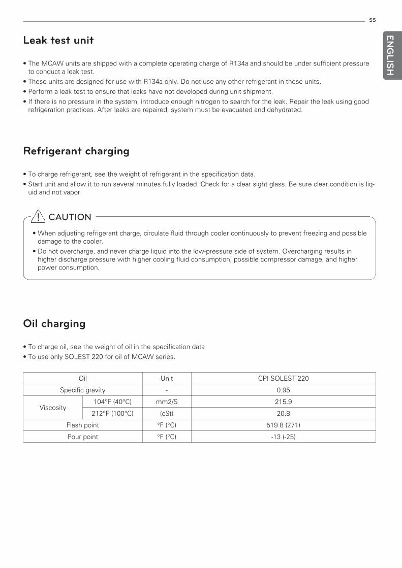
! CAUTION
• When adjusting refrigerant charge, circulate fluid through cooler continuously to prevent freezing and possibledamage to the cooler.
• Do not overcharge, and never charge liquid into the low-pressure side of system. Overcharging results inhigher discharge pressure with higher cooling fluid consumption, possible compressor damage, and higherpower consumption.
Oil Unit CPI SOLEST 220
Specific gravity - 0.95
Viscosity104°F (40°C) mm2/S 215.9
212°F (100°C) (cSt) 20.8
Flash point °F (°C) 519.8 (271)
Pour point °F (°C) -13 (-25)
• The MCAW units are shipped with a complete operating charge of R134a and should be under sufficient pressureto conduct a leak test.
• These units are designed for use with R134a only. Do not use any other refrigerant in these units.
• Perform a leak test to ensure that leaks have not developed during unit shipment.
• If there is no pressure in the system, introduce enough nitrogen to search for the leak. Repair the leak using goodrefrigeration practices. After leaks are repaired, system must be evacuated and dehydrated.
• To charge refrigerant, see the weight of refrigerant in the specification data.
• Start unit and allow it to run several minutes fully loaded. Check for a clear sight glass. Be sure clear condition is liq-uid and not vapor.
• To charge oil, see the weight of oil in the specification data
• To use only SOLEST 220 for oil of MCAW series.
55
ENG
LISH
Oil charging
Refrigerant charging
Leak test unit
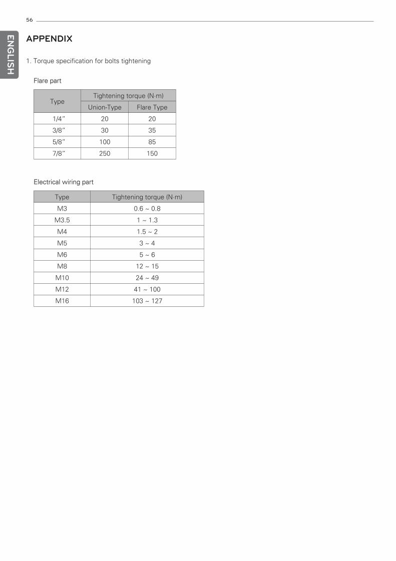
56
ENG
LISH
APPENDIX
1. Torque specification for bolts tightening
Flare part
Electrical wiring part
Type Tightening torque (N·m)
Union-Type Flare Type
1/4” 20 20
3/8” 30 35
5/8” 100 85
7/8” 250 150
Type Tightening torque (N·m)
M3 0.6 ~ 0.8
M3.5 1 ~ 1.3
M4 1.5 ~ 2
M5 3 ~ 4
M6 5 ~ 6
M8 12 ~ 15
M10 24 ~ 49
M12 41 ~ 100
M16 103 ~ 127