Embed Size (px)
Citation preview

OTC Series Air Cooled Chiller Operation and Installation Manual
Manual # O002639AD Date Effective: 05/22/2014

1
OTC Series Air Cooled Chiller Operation and Installation Manual
Page
Section 1 – Preface ......................................................................................................................... 2 Section 2 – About this Manual ......................................................................................................... 2
2.1 General .................................................................................................................................. 2 2.2 Warnings and Safety Symbols .............................................................................................. 2
Section 3 – General Information ...................................................................................................... 3 3.1 Safety Precautions ................................................................................................................ 3 3.2 Compliance ........................................................................................................................... 4 3.3 Service and Support .............................................................................................................. 4
Section 4 – Unpacking ..................................................................................................................... 5 4.1 Receiving / Inspection ........................................................................................................... 5 4.2 Handling, Transporting and Storage ..................................................................................... 5 4.3 Package Contents ................................................................................................................. 5
Section 5 – Description .................................................................................................................... 6 5.1 Overview of Liquid Chillers .................................................................................................... 6 5.2 Specifications and Available Options .................................................................................... 7 5.4 System Construction Standards .......................................................................................... 15
Section 6 – Installation .................................................................................................................. 15 6.1 Chiller Location .................................................................................................................... 15 6.2 Process Fluid Connection ................................................................................................... 15 6.3 Chilled Water Lines ............................................................................................................. 16 6.4 Overhead Piping and Drain Back Prevention .................................................................... 17 6.5 Electrical Connection .......................................................................................................... 17
Section 7 – Operation and Start Up............................................................................................... 18 7.1 General Start Up Information .............................................................................................. 18 7.2 Operating Temperature Range Limits ................................................................................. 19 7.3 Fluid Selection, Water Quality and Corrosion Protection .................................................... 19 7.4 Control Interface Layout ...................................................................................................... 19 7.5 Fluid Fill ............................................................................................................................... 20 7.6 Starting the Unit ................................................................................................................... 20 7.7 Temperature Setting and Adjustment ................................................................................. 20 7.8 Fluid Bypass Valve Setting and Adjustment ....................................................................... 23 7.9 System Fluid Drainage ........................................................................................................ 23
Section 8 – Maintenance ............................................................................................................... 24 Section 9 – Troubleshooting .......................................................................................................... 25
9.1 Low Refrigerant Check ........................................................................................................ 26 Section 10 – Replacement Parts ................................................................................................... 28 Section 11 – Warranty and Service ............................................................................................... 29 Section 12 – Appendix ................................................................................................................... 33
12.1 Dew Point / Temperature Chart ........................................................................................ 33 12.2 Description of Optional System Components ................................................................... 34 12.3 Electrical Schematic .......................................................................................................... 35 12.5 Refrigeration Diagram ....................................................................................................... 37 12.7 Water Quality Guidelines .................................................................................................. 39 12.8 Pump Curves ..................................................................................................................... 40 12.9 RoHS Material Table ......................................................................................................... 42 12.10 Electrical Interfacing ........................................................................................................ 43 12.11 Dimensional Drawings .................................................................................................... 44 12.12 Temperature Control Parameters ................................................................................... 45 12.13 Glycol Tables ................................................................................................................... 46 12.14 Notes ............................................................................................................................... 47
2
Section 1 – Preface
Thank you for choosing OPTI TEMP for your heat transfer equipment needs. We encourage your comments about our products and operation manual. Please feel free to contact us with questions or concerns at 231-946-2931 or [email protected]. We appreciate your business!
Section 2 – About this Manual
2.1 General
This manual is intended to serve as a guide for placing your portable chiller in service, operating it safely, and maintaining it properly. This manual will be supplemented as required to accommodate any special equipment which may have been provided for a specific application. NOTE: The written information contained in this manual, as well as various drawings, are intended to be general in nature. OPTI TEMP strives to maintain an accurate record of all equipment produced for the course of its useful life. While every effort is made to standardize the design features of these chillers, the various options may make it necessary to re-arrange some of the components; therefore, some of the general drawings in this manual may differ from your specific unit. We encourage all personnel to familiarize themselves with this manual’s contents. Failure to do so may unnecessarily prolong equipment down time.
2.2 Warnings and Safety Symbols
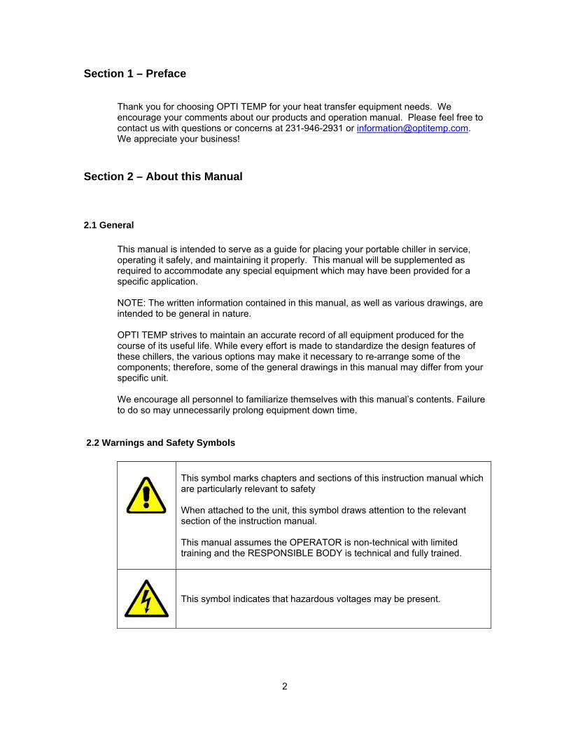
This symbol marks chapters and sections of this instruction manual which are particularly relevant to safety When attached to the unit, this symbol draws attention to the relevant section of the instruction manual. This manual assumes the OPERATOR is non-technical with limited training and the RESPONSIBLE BODY is technical and fully trained.
This symbol indicates that hazardous voltages may be present.
3
Section 3 – General Information
3.1 Safety Precautions Make sure you read and understand all instructions and safety precautions listed in this manual before installing or operating your unit. If you have any questions concerning the operation of your unit or the information in this manual, please contact our Sales Department at 231-946-2931 or [email protected].
• For safety reasons power supplies must be properly grounded. All federal, state, and local codes should be followed.
• Never use flammable or corrosive fluids with this unit. • Do not use automobile anti-freeze. Automotive anti-freeze often contains silicates or
other components that can damage your system. Only an un-inhibited glycol should be used. Use of automobile anti-freeze will void the manufacturer’s warranty.
• Never place the unit in a location where excessive heat, moisture, or corrosive materials are present.
• Do not modify or seal reservoir in any way. • Performance of installation, operation, or maintenance procedures other than
described in this manual may result in a hazardous situation and may void the manufacturer’s warranty.
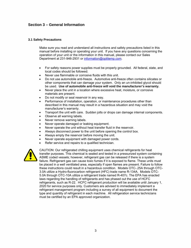
• Transport the unit with care. Sudden jolts or drops can damage internal components. • Observe all warning labels. • Never remove warning labels. • Never operate damaged or leaking equipment. • Never operate the unit without heat transfer fluid in the reservoir. • Always disconnect power to the unit before opening the control box. • Always empty the reservoir before moving the unit. • Never operate equipment with damaged power cords. • Refer service and repairs to a qualified technician. CAUTION: Our refrigerated chilling equipment uses chemical refrigerants for heat transfer purposes. This chemical is sealed and tested in a pressurized system containing ASME coded vessels; however, refrigerant gas can be released if there is a system failure. Refrigerant gas can cause toxic fumes if it is exposed to flame. These units must be placed in a well ventilated area, especially if open flames are present. Failure to follow these instructions could result in a hazardous condition. Models OTC-.25A through OTC-3.0A utilize a Hydro-fluorocarbon refrigerant (HFC) trade name R-134A. Models OTC-5.0A through OTC-10A utilize a refrigerant trade named R-407c. The EPA has enacted laws regarding the handling of refrigerants and has phased out the use of HCFC refrigerants, such as R-22. HCFC refrigerant production will be available until January 1, 2020 for service purposes only. Customers are advised to immediately implement a refrigerant management program including a survey of all equipment to document the type and quantity of refrigerant in each machine. All refrigeration service technicians must be certified by an EPA approved organization.
4
3.2 Compliance
CE: OPTI TEMP products are conformant per EN55011A, EN61326, EN61010-1. NRTL certification to UL 61010-1 part 1 is also available.
European RoHS: OPTI TEMP products do not fall under the scope of the RoHS directive per categories 8 (medical devices) and 9 (monitoring & control instruments).
WEEE: OPTI TEMP products with the WEEE mark should be collected, treated, recovered and environmentally disposed of directly through the OPTI TEMP collection scheme. Contact OPTI TEMP to determine the collection scheme for that particular location. As of August 13, 2005, all cooling system products introduced to the EU will be labeled with the "Crossed Wheelie Bin" symbol.
China RoHS: OPTI TEMP products are compliant per China RoHS guidelines. A RoHS material table, detailing the unit’s contents and respective toxic or hazardous substances or element levels is displayed in Section 12.8 Specification of this manual.
3.3 Service and Support
OPTI TEMP is committed to customer service both during and after the sale. If you have questions concerning the unit operation, please contact our Service Department at 231.946.2931. OPTI TEMP systems are built to provide years of trouble free service. All systems are tested prior to shipping to insure you receive the highest quality product. In the unlikely event you experience problems, rest assured our technical service staff will be available to assist you resolve any problems quickly. If your unit fails to operate properly, or if you have questions concerning spare parts or service, contact our customer service department at 231-946-2931 or [email protected]. Before calling, please refer to the serial number tag to obtain the serial number:
Unit Serial Number ___________________________________
5
Section 4 – Unpacking 4.1 Receiving / Inspection Each unit is skid mounted and either boxed or crated prior to shipment depending on size and/or shipping destination. Before accepting delivery, check the overall equipment condition for any visible damage. If damage is evident the unit should be thoroughly inspected in front of the delivery driver. Any and all damage should be properly documented on the delivery receipt. Shipping damage is the responsibility of the carrier. In order to expedite payment for damages it is important that proper procedures be followed and records kept. Photographs provide an excellent means of documenting damaged equipment. Once the unit is removed from the box or crate, it should be inspected for hidden damage. Refrigerant lines can be susceptible to damage in transit. Check for broken lines, oil leaks, damaged controls, or any other major component torn loose from its mounting point. NOTE: Any sign of damage should be recorded and a claim filed immediately with the shipping company. OPTITEMP will provide assistance in preparation and filing of your claims, including arranging for an estimate and quotation on repairs; however, filing the claim is the responsibility of the receiving party. NOTE: You may notice a small amount of fluid in your chiller system when it arrives. During the winter months (between October 1st and April 30th) a small amount of non-hazardous Propylene Glycol solution may be added to protect critical components from freeze damage. This solution can be flushed from the system prior to connecting to your process. Contact OPTI TEMP at 231-946-2931 or [email protected] with any questions or disposal concerns. 4.2 Handling, Transporting and Storage Smaller units are normally equipped with casters (two fixed and two swivel) to provide in-plant mobility. Proper rigging methods must be followed to prevent damage to components when removing units from pallets and/or placing into the desired service location. Avoid impact loading caused by sudden jerking when lifting or lowering the chiller. Use pads where abrasive surface contact is anticipated. The skid supporting the chiller can be used for positioning the unit with a fork lift. • Storage temperature: -10 to 55oC (14 to 131oF) • Operating ambient humidity conditions: 0 to 90 % relative humidity up to 40oC (non-
condensing), 10 to 50% relative humidity from 40 to 55oC (non-condensing) 4.3 Package Contents
• OTC Series Water Chiller • Operation and installation manual • Rubber vibration pads (optional) • Filters and spare cartridges (optional) • Hose Kits and/or other accessories (optional)
6
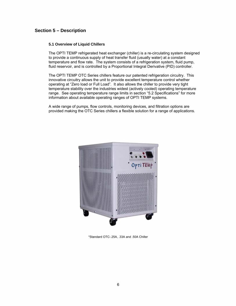
Section 5 – Description 5.1 Overview of Liquid Chillers The OPTI TEMP refrigerated heat exchanger (chiller) is a re-circulating system designed to provide a continuous supply of heat transfer fluid (usually water) at a constant temperature and flow rate. The system consists of a refrigeration system, fluid pump, fluid reservoir, and is controlled by a Proportional Integral Derivative (PID) controller. The OPTI TEMP OTC Series chillers feature our patented refrigeration circuitry. This innovative circuitry allows the unit to provide excellent temperature control whether operating at “Zero load or Full Load”. It also allows the chiller to provide very tight temperature stability over the industries widest (actively cooled) operating temperature range. See operating temperature range limits in section “5.2 Specifications” for more information about available operating ranges of OPTI TEMP systems. A wide range of pumps, flow controls, monitoring devices, and filtration options are provided making the OTC Series chillers a flexible solution for a range of applications.
*Standard OTC-.25A, .33A and .50A Chiller
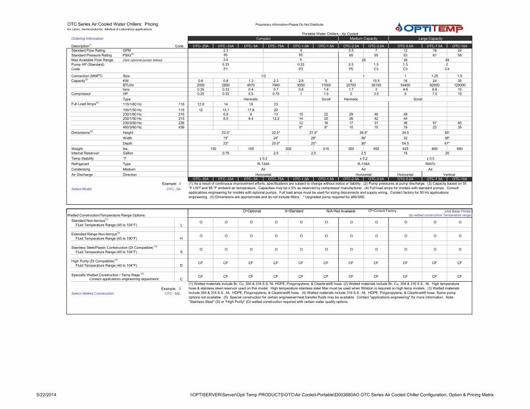
OTC Series Air Cooled Water Chillers: Pricing Proprietary Information-Please Do Not Distributefor Laser, Semiconductor, Medical & Laboratory applications
Ordering Information
Description(1) CodeStandard Flow Rating GPMStandard Pressure Rating PSIG(2)
Max Available Flow Range (See optional pumps below)
Connection (MNPT) SizeCapacity(3) KW
BTU/hrtons
Compressor HPType
Full Load Amps(4) 115/1/60 Hz100/1/50 Hz230/1/60 Hz230/1/50 Hz230/3/60 Hz460/3/60 Hz
Dimensions(5) HeightWidthDepth
Weight lbs.Internal Reservoir GallonTemp Stability °FRefrigerant TypeCondensing MediumAir Discharge Direction
Example: ⇓Select Model OTC-.5A
O=Optional S=Standard N/A=Not Available CF=Consult Factory Unit Base Prices
OTC-5.0A
Hermetic Scroll
38 48
Portable Water Chillers - Air CooledCompact Medium Capacity Large Capacity
OTC-.25A OTC-.33A OTC-.5A OTC-.75A OTC-1.0A OTC-1.5A OTC-2.0A OTC-3.0A OTC-7.5A OTC-10A24
53 615.5 7 12 18
582.3 4
3.5 5 2665 65 65 55
Pump HP (Standard) Code
0.33 P1
0.33 P3
0.5 P5
1.5 C3
1.5 C3
2 C4
1/2 1 1 1.25 1.50.6 0.8 1.3 2.3 2.8 5 6 10.5 16 24 35
2000 2800 4570 7940 9550 17000 20700 36100 54400 82000 1200000.25 0.33 0.4 0.7 0.8 1.4 1.7 3 4.5 6.8 100.25 0.33 0.5 0.75 1 1.5 2 3.5 5 7.5 10
Hermetic Scroll116 12.8 14 19 23115 12 13.1 17.8 20216 6.9 9 13 15 22 29 46 48215 6.5 8.4 12.2 14 20 26 42 44236 12 16 17 31 36 57 60436 6* 8* 10 15 19 23 35
22.5" 22.5" 27.5" 26.5" 34.5 55"
54.5 61"15" 24" 28" 36" 32 38"
155 205 215 350 45523" 25.5" 25" 36"
525 800 8500.75 2.5 2.5 2.5 15 20
130
± 0.2 ± 0.2 ± 0.5R-134A R-134A R407c
Air Air AirHorizontal Horizontal VerticalHorizontal
OTC-.25A OTC-.33A OTC-.5A OTC-.75A OTC-1.0A OTC-1.5A OTC-2.0A OTC-3.0A OTC-5.0A OTC-7.5A OTC-10A(1) As a result of continuous improvement efforts, specifications are subject to change without notice or liability. (2) Pump pressures at pump discharge. (3) Capacity based on 55 °F LWT and 95 °F ambient air temperature. Capacities may be ± 5% as reserved by compressor manufacturer. (4) Full load amps for models with standard pumps. Consult applications engineering for models with optional pumps. Full load amps must be used for sizing disconnects and supply wiring. Contact factory for 50 Hz applications engineering. (5) Dimensions are approximate and do not include filters. * Upgraded pump required for 460/3/60.
O Optional S Standard N/A Not Available y Unit Base PricesWetted Construction/Temperature Range Options: (by wetted construction/ Temperature range)
Standard Non-ferrous(1)
Fluid Temperature Range (45 to 104°F)
Extended Range Non-ferrous(2)
Fluid Temperature Range (45 to 190°F)
Stainless Steel/Plastic Contstruction (DI Compatible) (3)
Fluid Temperature Range (45 to 104°F)
High Purity (DI Compatible) (4)
Fluid Temperature Range (45 to 104°F)
Example: ⇓Select Wetted Construction OTC-.5AL
L O O O O O O O O O O O
H O O O O O O O O O O O
S O O O O O O O O O O O
DCF CF CF CF CF CF CF CF CF CF CF
Specialty Wetted Construction / Temp.Rage (5)
CCF CF CF CF CF CF CF CF CF CF CF
Contact applications engineering department.(1) Wetted materials include Br, Cu, 304 & 316 S.S. Ni, HDPE, Polypropylene, & Clearbraid® hose. (2) Wetted materials include Br, Cu, 304 & 316 S.S., Ni. High temperature hose & stainless steel reservoir used on this model. High temperature stainless steel filter must be used when filtration is required on high temp models. (3) Wetted materials include 304 & 316 S.S., Ni, HDPE, Polypropylene, & Clearbraid® hose. (4) Wetted materials include 316 S.S., Ni, HDPE, Polypropylene, & Clearbraid® hose. Some pump options not available. (5) Special construction for certain engineered heat transfer fluids may be available. Contact "applications engineering" for more information. Note: "Stainless Steel" (S) or "High Purity" (D) wetted construction required with certain water quality options.
5/22/2014 \\OPTISERVER\Server\Opti Temp PRODUCTS\OTC\Air Cooled-Portable\D003680AO OTC Series Air Cooled Chiller Configuration, Option & Pricing Matrix
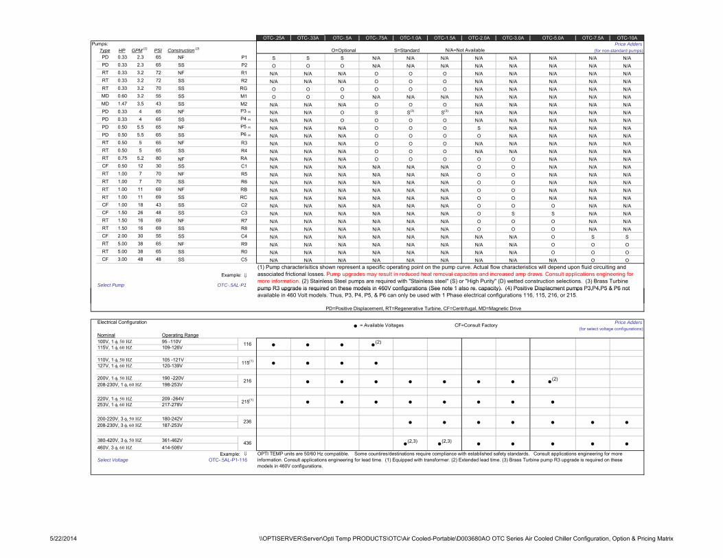
Pumps: Price AddersGPM (1) Construction (2) O=Optional S=Standard N/A=Not Available (for non-standard pumps)
NF P1SS P2NF R1SS R2
RT SS RGSS M1SS M2NF P3 (4)
SS P4 (4)
NF P5 (4)
SS P6 (4)
NF R3SS R4
RASS C1NF R5SS R6
RT NF RBRT SS RC
SS C2SS C3NF R7SS R8SS C4NF R9SS R0SS C5
Example: ⇓
Select Pump OTC-.5AL-P1
OTC-.25A OTC-.33A OTC-.5A OTC-.75A OTC-1.0A OTC-1.5A OTC-2.0A OTC-3.0A OTC-5.0A OTC-7.5A OTC-10A
Type HP PSIPD 0.33 2.3 65 S S S N/A N/A N/A N/A N/A N/A N/A N/APD 0.33 2.3 65 O O O N/A N/A N/A N/A N/A N/A N/A N/ART 0.33 3.2 72 N/A N/A N/A O O O N/A N/A N/A N/A N/ART 0.33 3.2 72 N/A N/A N/A O O O N/A N/A N/A N/A N/A
0.33 3.2 70 O O O O O O N/A N/A N/A N/A N/AMD 0.60 3.2 55 O O O N/A N/A N/A N/A N/A N/A N/A N/AMD 1.47 3.5 43 N/A N/A N/A O O O N/A N/A N/A N/A N/APD 0.33 4 65 N/A N/A O S S(3) S(3) N/A N/A N/A N/A N/APD 0.33 4 65 N/A N/A O O O O N/A N/A N/A N/A N/APD 0.50 5.5 65 N/A N/A N/A O O O S N/A N/A N/A N/APD 0.50 5.5 65 N/A N/A N/A O O O O N/A N/A N/A N/ART 0.50 5 65 N/A N/A N/A O O O N/A N/A N/A N/A N/ART 0.50 5 65 N/A N/A N/A O O O N/A N/A N/A N/A N/ART 0.75 5.2 80 NF N/A N/A N/A O O O O O N/A N/A N/ACF 0.50 12 30 N/A N/A N/A N/A N/A N/A O O N/A N/A N/ART 1.00 7 70 N/A N/A N/A N/A N/A N/A O O N/A N/A N/ART 1.00 7 70 N/A N/A N/A N/A N/A N/A O O N/A N/A N/A
CF 1.00 18 43 N/A N/A N/A N/A N/A N/A O O O N/A N/ACF 1.50 26 48 N/A N/A N/A N/A N/A N/A O S S N/A N/ART 1.50 16 69 N/A N/A N/A N/A N/A N/A O O O N/A N/ART 1.50 16 69 N/A N/A N/A N/A N/A N/A O O O N/A N/ACF 2.00 30 55 N/A N/A N/A N/A N/A N/A N/A N/A O S SRT 5.00 38 65 N/A N/A N/A N/A N/A N/A N/A N/A O O ORT 5.00 38 65 N/A N/A N/A N/A N/A N/A N/A N/A O O OCF 3.00 48 48 N/A N/A N/A N/A N/A N/A N/A N/A N/A O O
(1) Pump characterisitics shown represent a specific operating point on the pump curve. Actual flow characteristics will depend upon fluid circuiting and associated frictional losses. Pump upgrades may result in reduced heat removal capacites and increased amp draws. Consult applications engineering for more information. (2) Stainless Steel pumps are required with "Stainless steel" (S) or "High Purity" (D) wetted construction selections. (3) Brass Turbine pump R3 upgrade is required on these models in 460V configurations (See note 1 also re. capacity). (4) Positive Displacment pumps P3,P4,P5 & P6 not
1.00 69 N/A N/A N/A N/A N/A N/A O O N/A N/A N/A1.00 69 N/A N/A N/A N/A N/A N/A O O N/A N/A N/A
1111
PD=Positive Displacement, RT=Regenerative Turbine, CF=Centrifugal, MD=Magnetic Drive
Electrical Configuration Price Adders(for select voltage configurations)
Nominal Operating Range100V, 1 φ, 50 ΗΖ 95 -110V115V, 1 φ, 60 ΗΖ 109-126V
110V, 1 φ, 50 ΗΖ 105 -121V127V, 1 φ, 60 ΗΖ 120-139V
200V, 1 φ, 50 ΗΖ 190 -220V208-230V, 1 φ, 60 ΗΖ 198-253V
220V, 1 φ, 50 ΗΖ 209 -264V253V, 1 φ, 60 ΗΖ 217-278V
200-220V, 3 φ, 50 ΗΖ 180-242V208-230V, 3 φ, 60 ΗΖ 187-253V
380-420V, 3 φ, 50 ΗΖ 361-462V460V, 3 φ, 60 ΗΖ 414-506V
Example: ⇓Select Voltage OTC-.5AL-P1-116
pump R3 upgrade is required on these models in 460V configurations (See note 1 also re. capacity). (4) Positive Displacment pumps P3,P4,P5 & P6 not available in 460 Volt models. Thus, P3, P4, P5, & P6 can only be used with 1 Phase electrical configurations 116, 115, 216, or 215.
• = Available Voltages CF=Consult Factory
116 • • • •(2)
115(1) • • • •
216 • • • • • • • •(2)
215(1) • • • • • • • •
236 • • • • • • •
• •436 •(2,3) •(2,3) • • •OPTI TEMP units are 50/60 Hz compatible. Some countires/destinations require compliance with established safety standards. Consult applications engineering for more information. Consult applications engineering for lead time. (1) Equipped with transformer. (2) Extended lead time. (3) Brass Turbine pump R3 upgrade is required on these models in 460V configurations.
5/22/2014 \\OPTISERVER\Server\Opti Temp PRODUCTS\OTC\Air Cooled-Portable\D003680AO OTC Series Air Cooled Chiller Configuration, Option & Pricing Matrix
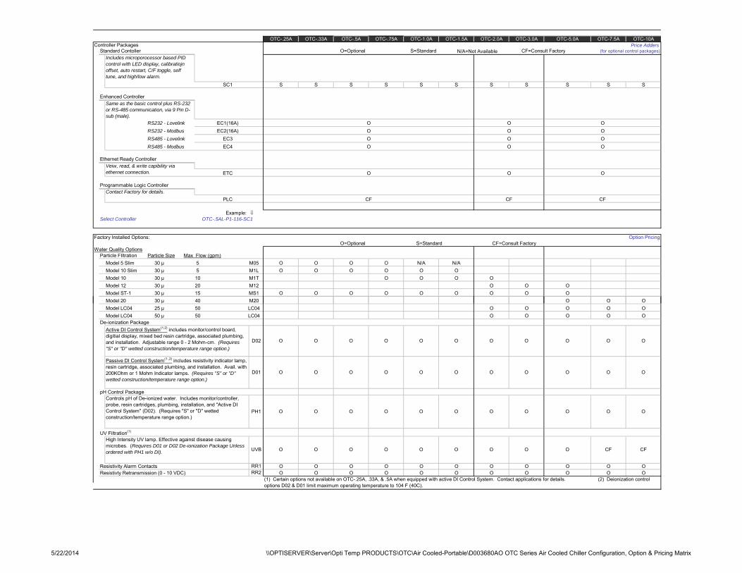
Controller Packages Price AddersStandard Contoller O=Optional S=Standard N/A=Not Available CF=Consult Factory (for optional control packages)
Enhanced Controller
RS232 - LovelinkRS232 - ModbusRS485 - LovelinkRS485 - Modbus
Ethernet Ready Controller
Programmable Logic Controller
Example: ⇓Select Controller OTC-.5AL-P1-116-SC1
Factory Installed Options: Option PricingO=Optional S=Standard CF=Consult Factory
Water Quality OptionsParticle FIltration Particle Size Max Flow (gpm)
Model 5 Slim 30 µModel 10 Slim 30 µModel 10 30 µModel 12 30 µModel ST-1 30 µ
OTC-2.0A OTC-7.5A OTC-10A
S
EC2(16A) O O O
OTC-3.0A OTC-5.0AOTC-.25A OTC-.33A OTC-.5A OTC-.75A OTC-1.0A OTC-1.5A
EC3 O O O
S S
EC4 O O O
Veiw, read, & write capibility via ethernet connection. ETC O O O
S S
Includes microporocessor based PID control with LED display, calibratiojn offset, auto restart, C/F toggle, self tune, and high/low alarm.
SC1 S S S
Same as the basic control plus RS-232 or RS-485 communication, via 9 Pin D-sub (male).
EC1(16A) O O O
S S S
Contact Factory for details.PLC CF CF CF
5 M05 O O O O N/A N/A5 M1L O O O O O O10 M1T O O O O20 M12 O O O15 MS1 O O O O O O O O O
Model 20 30 µModel LC04 25 µModel LC04 50 µ
De-ionization Package
pH Control Package
UV Filtration(1)
Resistivity Alarm Contacts Resistivty Retransmission (0 - 10 VDC)
40 M20 O O O50 LC04 O O O O O50 LC04 O O O O O
Active DI Control System(1,2) includes monitor/control board, digitial display, mixed bed resin cartridge, associated plumbing, and installation. Adjustable range 0 - 2 Mohm-cm. (Requires "S" or "D" wetted construction/temperature range option.)
D02 O O O O O O O O O O O
Passive DI Control System(1.,2) includes resistivity indicator lamp, resin cartridge, associated plumbing, and installation. Avail. with 200KOhm or 1 Mohm Indicator lamps. (Requires "S" or "D" wetted construction/temperature range option.)
D01 O O O O O O O O O O O
Controls pH of De-ionized water. Includes monitor/controller, probe, resin cartridges, plumbing, installation, and "Active DI Control System" (D02). (Requires "S" or "D" wetted construction/temperature range option.)
PH1 O O O O O O O O O O O
High Intensity UV lamp. Effective against disease causing microbes. (Requires D01 or D02 De-ionization Package Unless ordered with PH1 w/o DI). UVB O O O O O O O O O CF CF
RR1 O O O O O O O O O O ORR2 O O O O O O O O O O O
(1) Certain options not available on OTC-.25A, .33A, & .5A when equipped with active DI Control System. Contact applications for details. (2) Deionization control options D02 & D01 limit maximum operating temperature to 104 F (40C).
5/22/2014 \\OPTISERVER\Server\Opti Temp PRODUCTS\OTC\Air Cooled-Portable\D003680AO OTC Series Air Cooled Chiller Configuration, Option & Pricing Matrix
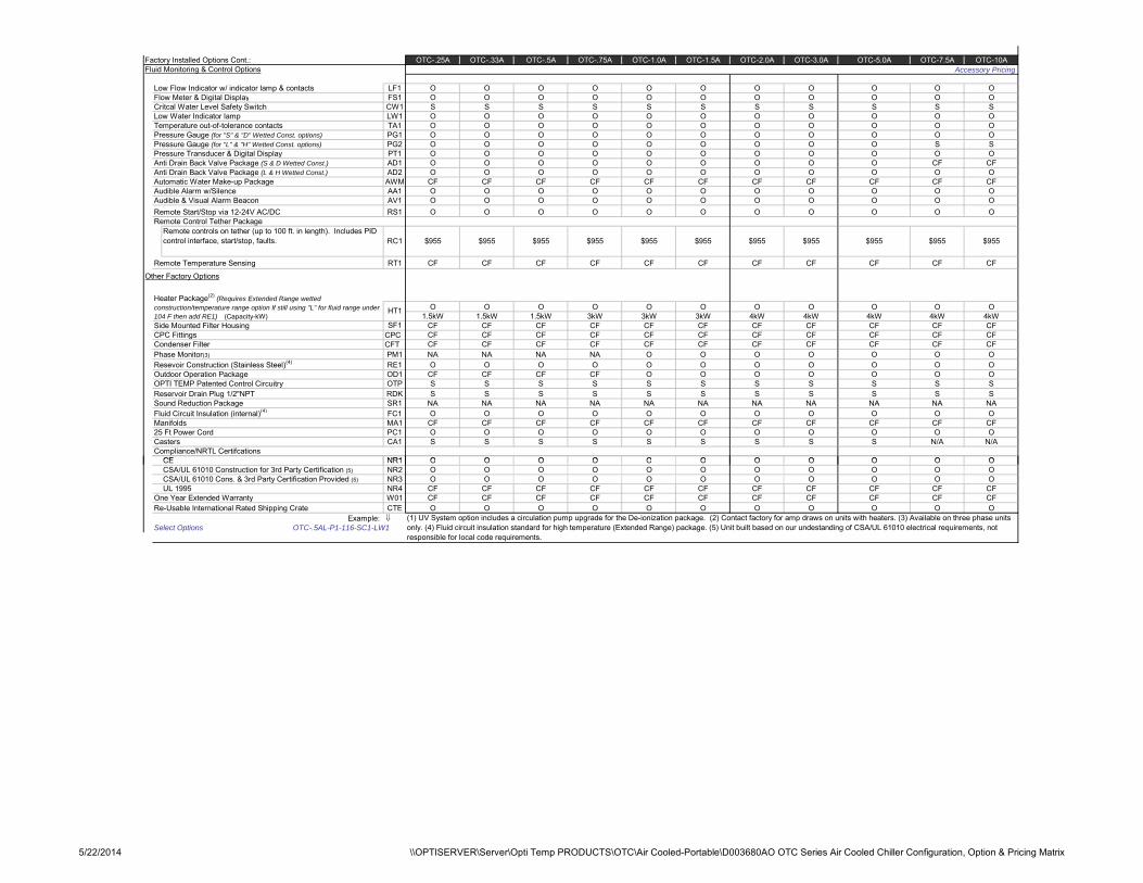
Factory Installed Options Cont.:Fluid Monitoring & Control Options Accessory Pricing
Low Flow Indicator w/ indicator lamp & contactsFlow Meter & Digital DisplayCritcal Water Level Safety SwitchLow Water Indicator lampTemperature out-of-tolerance contactsPressure Gauge (for "S" & "D" Wetted Const. options)Pressure Gauge (for "L" & "H" Wetted Const. options)Pressure Transducer & Digital DisplayAnti Drain Back Valve Package (S & D Wetted Const.)Anti Drain Back Valve Package (L & H Wetted Const.)Automatic Water Make-up PackageAudible Alarm w/Silence Audible & Visual Alarm BeaconRemote Start/Stop via 12-24V AC/DCRemote Control Tether Package
Remote Temperature Sensing
Other Factory Options
Side Mounted Filter HousingCPC Fittings CPCCondenser Filter CFTPhase Monitor(3)
Resevoir Construction (Stainless Steel)(4)
Outdoor Operation PackageOPTI TEMP Patented Control CircuitryReservoir Drain Plug 1/2"NPTSound Reduction PackageFluid Circuit Insulation (internal)(4)
Manifolds25 Ft Power CordCastersCompliance/NRTL Certifcations
CE
OTC-.25A OTC-.33A OTC-.5A OTC-.75A OTC-1.0A OTC-1.5A OTC-2.0A OTC-3.0A OTC-5.0A OTC-7.5A OTC-10A
LF1 O O O O O O O O O O OFS1 O O O O O O O O O O OCW1 S S S S S S S S S S SLW1 O O O O O O O O O O OTA1 O O O O O O O O O O OPG1 O O O O O O O O O O OPG2 O O O O O O O O O S SPT1 O O O O O O O O O O OAD1 O O O O O O O O O CF CFAD2 O O O O O O O O O O OAWM CF CF CF CF CF CF CF CF CF CF CFAA1 O O O O O O O O O O OAV1 O O O O O O O O O O ORS1 O O O O O O O O O O O
Remote controls on tether (up to 100 ft. in length). Includes PID control interface, start/stop, faults. RC1 $955 $955 $955 $955 $955 $955 $955 $955 $955 $955 $955
RT1 CF CF CF CF CF CF CF CF CF CF CF
Heater Package(2) (Requires Extended Range wetted construction/temperature range option If still using "L" for fluid range under 104 F then add RE1) (Capacity-kW)
HT1 O O O O O O O O O O O1.5kW 1.5kW 1.5kW 3kW 3kW 3kW 4kW 4kW 4kW 4kW 4kW
SF1 CF CF CF CF CF CF CF CF CF CF CFCF CF CF CF CF CF CF CF CF CF CFCF CF CF CF CF CF CF CF CF CF CF
PM1 NA NA NA NA O O O O O O ORE1 O O O O O O O O O O OOD1 CF CF CF CF O O O O O O OOTP S S S S S S S S S S SRDK S S S S S S S S S S SSR1 NA NA NA NA NA NA NA NA NA NA NAFC1 O O O O O O O O O O OMA1 CF CF CF CF CF CF CF CF CF CF CFPC1 O O O O O O O O O O OCA1 S S S S S S S S S N/A N/A
NR1 O O O O O O O O O O OCECSA/UL 61010 Construction for 3rd Party Certification (5)CSA/UL 61010 Cons. & 3rd Party Certification Provided (5)UL 1995
One Year Extended WarrantyRe-Usable International Rated Shipping Crate
Example: ⇓Select Options OTC-.5AL-P1-116-SC1-LW1
NR1 O O O O O O O O O O ONR2 O O O O O O O O O O ONR3 O O O O O O O O O O ONR4 CF CF CF CF CF CF CF CF CF CF CFW01 CF CF CF CF CF CF CF CF CF CF CFCTE O O O O O O O O O O O
(1) UV System option includes a circulation pump upgrade for the De-ionization package. (2) Contact factory for amp draws on units with heaters. (3) Available on three phase units only. (4) Fluid circuit insulation standard for high temperature (Extended Range) package. (5) Unit built based on our undestanding of CSA/UL 61010 electrical requirements, not responsible for local code requirements.
5/22/2014 \\OPTISERVER\Server\Opti Temp PRODUCTS\OTC\Air Cooled-Portable\D003680AO OTC Series Air Cooled Chiller Configuration, Option & Pricing Matrix
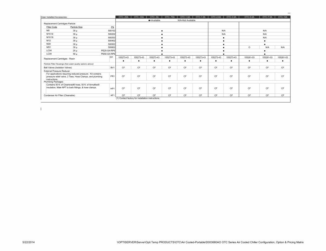
User Installed Accsssories:N/A=Not Available
Replacement Cartridges-ParticleFilter Code Particle SizeM5 30 µM10 Sl 30 µM10 St 30 µM12 30 µM20 30 µMS1 30 µLC04 25 µLC04 50 µ
DI1
Particle Filter Housings (See water quality options above)
Ball Valves (Isolation Valves)External Pressure Reducer
Plumbing Packages
Condenser Air Filter (Cleanable)(1) Contact factory for installation instructions.
OTC-.25A OTC-.33A OTC-.5A OTC-.75A OTC-1.0A OTC-1.5A OTC-2.0A OTC-3.0A OTC-5.0A OTC-7.5A OTC-10A■=Available
PN500102 ■ N/A N/A500202 ■ N/A N/A500202 ■ ■ N/A500402 ■ ■ ■500502 ■ ■ ■500602 ■ ■ O N/A N/A
PE25-G4-RPE ■ ■ ■PE50-G4-RPE ■ ■ ■
Replacement Cartridges - Resin 155273-43 155273-43 155273-43 155273-43 155273-43■ ■ ■ ■
155273-43 155273-43 155273-43 155281-03 155281-03 155281-03■ ■ ■ ■ ■ ■ ■
BV1 CF CF CF CF CF CF CF CF CF CF CF
For applications requiring reduced pressure. Kit contains pressure relief valve, 2 Tees, Hose Clamps, and plumbing instructions.
PR1 CF CF CF CF CF CF CF CF CF CF CF
Contains 50 ft. of Clearbraid® hose, 50 ft. of Armaflex® insulation, Male NPT to barb fittings, & hose clamps. CF CF CF CF CF CF CF CF CF CF CFHP1
AF1 CF CF CF CF CF CF CF CF CF CF CF
5/22/2014 \\OPTISERVER\Server\Opti Temp PRODUCTS\OTC\Air Cooled-Portable\D003680AO OTC Series Air Cooled Chiller Configuration, Option & Pricing Matrix

12
5.3 Description Standard System Components Coolant Circuit The pump draws coolant from the reservoir and circulates it to the process and returns it to the evaporator. It is in the evaporator where the heat is transferred from the coolant to the refrigerant. Adjusting the amount of heat transferred in the evaporator controls the temperature of the coolant being delivered to the process. There is a freezestat sensor and flow switch (optional) in the coolant circuit to serve as safety controls. There is also a thermocouple to sense the temperature of the coolant being delivered to process and communicates this temperature to the microprocessor based PID temperature controller. An adjustable bypass valve allows the chiller to operate with sufficient flow through the evaporator even if the flow is restricted or completely shut off through the process. NOTE: Closing the bypass valve off too far may result in a situation that could damage components in the chiller. The main purpose of the bypass line is to avoid deadheading of the pump and reduce the possibility of an evaporator freeze-up. See Section 7.8 for more information on adjusting the bypass valve.
Refrigerant Circuit -Advanced Refrigeration Control Circuitry (ARCC) The OTC Series Chillers features our “Advanced Refrigeration Capacity Control” (ARCC) circuitry. This patented circuitry allows the unit to operate from “zero load to full load” (without cycling the compressor) while providing excellent temperature stability. Another benefit is the ability to operate over a very wide temperature range.
The patented refrigeration control circuitry adjusts and controls the flow of refrigerant in response to the process load. The circuitry provides only the needed cooling capacity. Because of this innovative circuitry, the refrigeration system compressor will operate when the unit is on regardless of whether or not the process calls for cooling. This is normal and is not a cause for concern. Continuous compressor operation reduces wear and tear associated with frequent cycling which can lead to premature compressor failure.
The heat that is transferred in the evaporator from the coolant to the refrigerant is used to change the state of the refrigerant from a liquid to a gas. After leaving the evaporator, the refrigerant passes to the compressor.
Compressor The OTC Series Chillers are equipped with a hermetic reciprocating or hermetic scroll compressor, depending on model. Both the compressor and the motor are encased together and solidly mounted in the cabinet. The compressor is unidirectional and will only pump refrigerant when properly phased. The cool refrigerant suction gas cools the motor windings, and there is an internal thermal overload to protect the windings from overheating. The compressor is lubricated with oil that travels throughout the system with the refrigerant. NOTE: The compressor on OPTI TEMP OTC Series chillers runs continuously regardless of load on the system. This is normal and not a cause for concern.
Air Cooled Condenser This component is only used in the air cooled chillers. The condenser is constructed of heavy gauge copper tubing and aluminum fins for maximum heat transfer capabilities. The condenser has been generously sized so the chiller can operate with full cooling capacities in ambient air temperatures of up to 95°F (35°C). When the ambient air temperatures are above 95°F (35°C) the chiller will lose approximately 1% of its cooling capacity per 1°F (0.5°C) above 95°F (35°C). The chiller should be able to operate with ambient temperatures of up to 110°F (43°C). The fan(s) draw the air flow through the condenser and blows the warm discharge air through the chiller cabinet and out the other side. The fan(s) are designed to draw sufficient air flow through the chiller as long as there are no obstructions. The fan(s) are
13
not capable of drawing air in through ductwork on the intake or discharging air through ductwork on the exhaust. The discharge air will be significantly warmer than the intake air.
Evaporator The standard evaporator is constructed of stainless steel plates and copper brazing. (An optional “nickel brazed” evaporator is available with the high purity construction option.) The refrigerant passes between every other set of plates, while the coolant flows on the other side of the plates in the opposite direction. Thermostatic Expansion Valve This valve (referred to as the TXV) separates the high pressure/high temperature side of the refrigeration circuit (the condenser side) from the low pressure/low temperature side of the refrigeration circuit (the evaporator side). The TXV maintains constant superheat at the evaporator outlet, regardless of process load, by precisely metering the amount of refrigerant into the evaporator. Superheat is the difference between the saturated evaporative temperature and the actual measured temperature at the TXV sensor bulb. The superheat is factory set for 10°F to 12°F (5°C to 6°C) and should never exceed 15°F (8°C). Only a trained refrigeration technician should adjust refrigeration system valves. Refrigerant Sight Glass The refrigerant sight glass is located in the liquid line ahead of the expansion valve. It allows the operator or service technician to observe the flow of liquid refrigerant. Prolonged periods of foaming in the sight glass may indicate a low refrigerant condition or a restriction in the liquid line. Occasional bubbling in the sight glass may occur at a time when load conditions are changing and the thermostatic expansion valve is adjusting to the new conditions. This momentary occurrence is a result of normal chiller operation. The sight glass can also be used to check if there is moisture in the refrigeration system. If there is moisture in the system, the green dot in the center of the sight glass will turn yellow. If this occurs, the chiller should be serviced immediately. Refrigerant Filter Drier The filter drier is located in the liquid line between the condenser and the refrigerant sight glass. It is designed to remove any moisture and/or foreign matter that may have gotten into the refrigerant stream. Moisture and foreign matter can cause serious damage to the components of a refrigeration system. For this reason, it is important that the chiller be equipped with a clean filter drier. Replace the filter drier if any of the following conditions occur: 1. The refrigeration system is opened to the atmosphere for repairs or maintenance. 2. Moisture is indicated in the sight glass (the green dot has changed to yellow). 3. An Excessive pressure drop develops across the filter drier. This is indicated by a significant temperature difference between the filter inlet and outlet. Pressure Relief Valve / Blow Out Plug The pressure relief valve is located in the liquid line after the condenser. It is designed to relieve refrigerant pressure under severe conditions in order to protect the refrigeration circuit components from damage. Hot Gas Bypass Valve This valve is located in the refrigerant line that runs from the compressor discharge to the evaporator inlet. It is designed to artificially load the chiller when the chiller is catering to a partial load from the process. This is accomplished by directing some of the hot compressor discharge gas directly back into the evaporator instead of going through the condenser. The microprocessor based PID temperature controller controls the amount of hot gas used.
14
Solenoid Valve The solenoid valve is controlled by the microprocessor based PID temperature controller and supplies adequate amount of refrigerant necessary to cool the process fluid to the desired temperature. Reservoir The reservoir material will vary depending upon the materials of construction option selected. There is a removable cover on the top of the reservoir. During chiller operation the reservoir should be at least half full. For most installations the reservoir has sufficient capacity to handle coolant drain back from the process equipment which occurs during chiller shut down. For installations with overhead piping special precautions will have to be made during installation. Contact OPTI TEMP customer service department for details at 231-946-2931 or [email protected]. NOTE: The reservoir must not be pressurized. Modifications to the chiller that would result in pressurization of the reservoir will void the warranty. Coolant Pump The standard close coupled pump is typically equipped with a mechanical seal. Material of construction and seal type will vary by model and the options selected. The pump is factory tested for the specified operating conditions and meets NEMA specifications / industry standards. High Refrigerant Pressure Switch The High Refrigerant Pressure switch is designed to limit the compressor discharge pressure within the design parameters of the compressor. The switch is located on the discharge side of the compressor. All models feature automatic reset switches. Low Refrigerant Pressure Switch The Low Refrigerant Pressure switch is designed to limit the compressor suction pressure to within the designed parameters of the compressor. The switch is located in the suction side of the compressor. The low pressure refrigerant switch is an automatic reset switch. Freezestat The freezestat control is an electronic thermostat most commonly used that senses the coolant temperature separately from the microprocessor based PID temperature controller. The PID controller is sometimes used as the freezestat. This safety is designed to limit the temperature of the coolant leaving the evaporator and prevent a possible freeze up situation. This control should be set 10°F (5°C) below the minimum coolant supply temperature, and there should be a sufficient glycol concentration for 10°F (5°C) below the freezestat setting. NOTE: It is critical that the freezestat is set properly and that there is sufficient glycol in the system to correspond with the freezestat setting. Freeze ups can cause extensive damage to several components in the chiller, and the warranty does not cover repairs required due to a freeze up.
15
5.4 System Construction Standards OPTI TEMP standard chillers are designed with NEMA 1 construction suitable for indoor use. Unless the unit was specifically ordered with NEMA 4 construction for outdoor duty, it should not be installed or stored in an outdoor location.
Section 6 – Installation
6.1 Chiller Location The OPTI TEMP units utilize air-cooled refrigeration systems and must be placed in well ventilated areas only. Air is drawn and/or discharged through the front, rear, side and top panels of the unit. The unit must be located so the intake and discharge air is not restricted. A minimum clearance of “one width” of the unit is suggested on all vented sides. Failure to provide adequate ventilation may cause a reduction in cooling capacity, excessively high refrigeration pressures, and/or pre-mature failure. Never place the unit in a location where excessive heat, moisture, airborne oils, or corrosive materials are present. The unit should be periodically cleaned to insure optimum performance. A regular maintenance schedule based on operating conditions is recommended. Please reference Section 8 of this manual for more information. Please note that oil, dust, and/or other airborne agents can build up on air-cooled condensers resulting in a decrease in performance or system failure. NOTE: Serviceability was a primary concern when designing your portable chiller. Removable panels permit easy access for periodic maintenance or repair. Do not compromise this feature by locating the chiller in an inaccessible area. NOTE: The condenser air inlet temperature should be maintained above 60°F (15°C) in order to avoid possible low refrigerant pressure safety trips during start-up. If it is necessary to store the chiller in an unheated area when not in use, be sure that all water is drained or that an adequate amount of antifreeze is added to prevent freeze-up of the unit. 6.2 Process Fluid Connection Connect “TO PROCESS” and “FROM PROCESS” connections on rear of chiller to your process lines. Standard process connections provided on OTC Series chillers are stainless steel male pipe fittings. See specifications table in Section 5.2 for connection sizes on specific chiller models. It is suggested that valves be installed on the “TO PROCESS” line and “FROM PROCESS” line at the OPTI TEMP unit to be used as balancing valves and to isolate the chiller should maintenance be required on the unit.
16
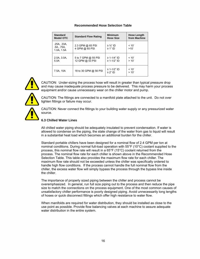
Recommended Hose Selection Table CAUTION: Under-sizing the process hose will result in greater than typical pressure drop and may cause inadequate process pressure to be delivered. This may harm your process equipment and/or cause unnecessary wear on the chiller motor and pump. CAUTION: The fittings are connected to a manifold plate attached to the unit. Do not over tighten fittings or failure may occur. CAUTION: Never connect the fittings to your building water supply or any pressurized water source. 6.3 Chilled Water Lines All chilled water piping should be adequately insulated to prevent condensation. If water is allowed to condense on the piping, the state change of the water from gas to liquid will result in a substantial heat load which becomes an additional burden for the chiller. Standard portable chillers have been designed for a nominal flow of 2.4 GPM per ton at nominal conditions. During normal full-load operation with 55°F (10°C) coolant supplied to the process, this nominal flow rate will result in a 65°F (15°C) coolant returned from the process. The nominal flow rate for each chiller is shown above in the Recommended Hose Selection Table. This table also provides the maximum flow rate for each chiller. The maximum flow rate should not be exceeded unless the chiller was specifically ordered to handle high flow conditions. If the process cannot handle the full nominal flow from the chiller, the excess water flow will simply bypass the process through the bypass line inside the chiller. The importance of properly sized piping between the chiller and process cannot be overemphasized. In general, run full size piping out to the process and then reduce the pipe size to match the connections on the process equipment. One of the most common causes of unsatisfactory chiller performance is poorly designed piping. Avoid unnecessarily long lengths of hoses or quick disconnect fittings which offer high resistance to water flow. When manifolds are required for water distribution, they should be installed as close to the use point as possible. Provide flow balancing valves at each machine to assure adequate water distribution in the entire system.
Standard Model OTC Standard Flow Rating Minimum
Hose Size Hose Length from Machine
.25A, .33A,
.5A, .75A, 1.0A, 1.5A
2.3 GPM @ 65 PSI 4 GPM @ 65 PSI
≥ ¾” ID ≥ 1” ID
< 10’ >10’
2.0A, 3.0A, 5.0A
5 to 7 GPM @ 55 PSI 12 GPM @ 53 PSI
≥ 1-1/4” ID ≥ 1-1/2” ID
< 10’ > 10’
7.5A, 10A 18 to 30 GPM @ 56 PSI
≥ 1-1/2” ID ≥ 2” ID
< 10’ > 10’
17
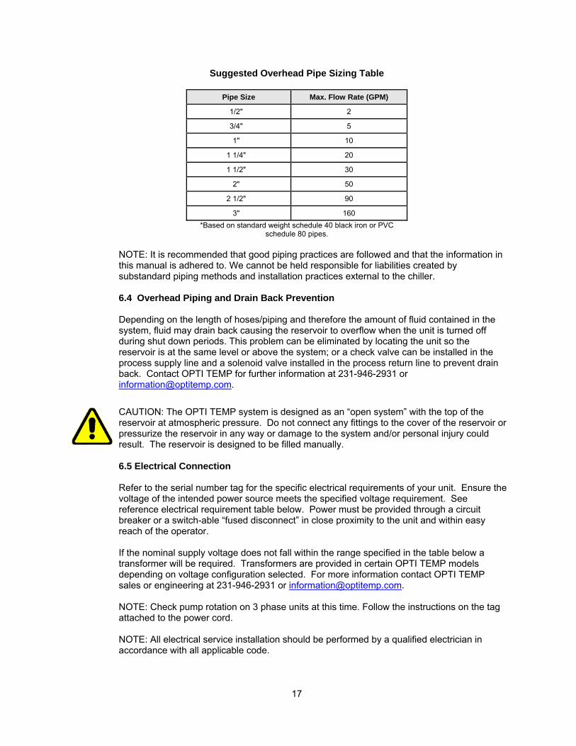
Suggested Overhead Pipe Sizing Table
Pipe Size Max. Flow Rate (GPM)
1/2" 2
3/4" 5
1" 10
1 1/4" 20
1 1/2" 30
2" 50
2 1/2" 90
3" 160 *Based on standard weight schedule 40 black iron or PVC
schedule 80 pipes. NOTE: It is recommended that good piping practices are followed and that the information in this manual is adhered to. We cannot be held responsible for liabilities created by substandard piping methods and installation practices external to the chiller.
6.4 Overhead Piping and Drain Back Prevention
Depending on the length of hoses/piping and therefore the amount of fluid contained in the system, fluid may drain back causing the reservoir to overflow when the unit is turned off during shut down periods. This problem can be eliminated by locating the unit so the reservoir is at the same level or above the system; or a check valve can be installed in the process supply line and a solenoid valve installed in the process return line to prevent drain back. Contact OPTI TEMP for further information at 231-946-2931 or [email protected].
CAUTION: The OPTI TEMP system is designed as an “open system” with the top of the reservoir at atmospheric pressure. Do not connect any fittings to the cover of the reservoir or pressurize the reservoir in any way or damage to the system and/or personal injury could result. The reservoir is designed to be filled manually. 6.5 Electrical Connection Refer to the serial number tag for the specific electrical requirements of your unit. Ensure the voltage of the intended power source meets the specified voltage requirement. See reference electrical requirement table below. Power must be provided through a circuit breaker or a switch-able “fused disconnect” in close proximity to the unit and within easy reach of the operator. If the nominal supply voltage does not fall within the range specified in the table below a transformer will be required. Transformers are provided in certain OPTI TEMP models depending on voltage configuration selected. For more information contact OPTI TEMP sales or engineering at 231-946-2931 or [email protected]. NOTE: Check pump rotation on 3 phase units at this time. Follow the instructions on the tag attached to the power cord. NOTE: All electrical service installation should be performed by a qualified electrician in accordance with all applicable code.
18
NOTE: Due to variation in required plug configurations OPTI TEMP units are shipped without a plug on the power cord.
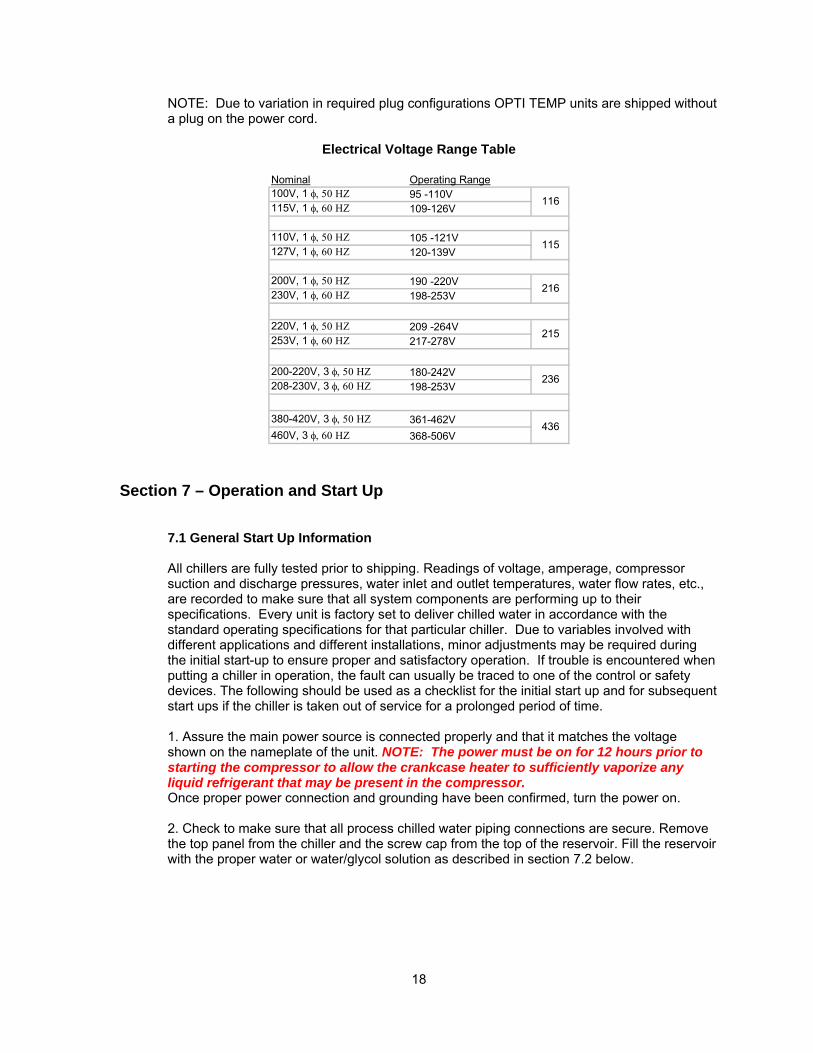
Electrical Voltage Range Table
Nominal Operating Range100V, 1 φ, 50 ΗΖ 95 -110V115V, 1 φ, 60 ΗΖ 109-126V
110V, 1 φ, 50 ΗΖ 105 -121V127V, 1 φ, 60 ΗΖ 120-139V
200V, 1 φ, 50 ΗΖ 190 -220V230V, 1 φ, 60 ΗΖ 198-253V
220V, 1 φ, 50 ΗΖ 209 -264V253V, 1 φ, 60 ΗΖ 217-278V
200-220V, 3 φ, 50 ΗΖ 180-242V208-230V, 3 φ, 60 ΗΖ 198-253V
380-420V, 3 φ, 50 ΗΖ 361-462V460V, 3 φ, 60 ΗΖ 368-506V
216
215
436
236
116
115
Section 7 – Operation and Start Up
7.1 General Start Up Information All chillers are fully tested prior to shipping. Readings of voltage, amperage, compressor suction and discharge pressures, water inlet and outlet temperatures, water flow rates, etc., are recorded to make sure that all system components are performing up to their specifications. Every unit is factory set to deliver chilled water in accordance with the standard operating specifications for that particular chiller. Due to variables involved with different applications and different installations, minor adjustments may be required during the initial start-up to ensure proper and satisfactory operation. If trouble is encountered when putting a chiller in operation, the fault can usually be traced to one of the control or safety devices. The following should be used as a checklist for the initial start up and for subsequent start ups if the chiller is taken out of service for a prolonged period of time. 1. Assure the main power source is connected properly and that it matches the voltage shown on the nameplate of the unit. NOTE: The power must be on for 12 hours prior to starting the compressor to allow the crankcase heater to sufficiently vaporize any liquid refrigerant that may be present in the compressor. Once proper power connection and grounding have been confirmed, turn the power on. 2. Check to make sure that all process chilled water piping connections are secure. Remove the top panel from the chiller and the screw cap from the top of the reservoir. Fill the reservoir with the proper water or water/glycol solution as described in section 7.2 below.
19
7.2 Operating Temperature Range Limits
OPTI TEMP systems are designed to operate at fluid temperatures within a certain specified temperature range. All systems are not designed to operate over the same range. It is important that you do not operate the system outside of this intended range. Please refer to the specifications in section 5.2 Specifications and Available Options for details on the operating temperature limits.
CAUTION: Do not operate units outside recommended temperature range. System damage and/or personal injury may result. 7.3 Fluid Selection, Water Quality and Corrosion Protection Generally, OPTI TEMP recommends the use of distilled or de-ionized water instead of tap water because tap water often has high level of total ionized solids which can accelerate corrosion. These contaminants function as electrolytes which increase the potential for galvanic corrosion. Tap water in the US averages 175 ppm sodium chloride (NaCl). The recommended level for NaCl is between 0.5 to 5 ppm. Normally OPTI TEMP recommends that systems, which require a fluid conductivity below 240 microsiemans/cm, utilize stainless steel construction. Systems where conductivities are permitted to be above 240 microsiemans/cm may use a corrosion inhibitor such as OPTISHIELD® to control corrosion and extend system life. Note: Before using a corrosion inhibitor or Optishield, flush out the system and refill with water/glycol to remove any possible construction debris that may be present in the reservoir or fluid lines. When using any corrosion inhibitor it is absolutely essential to install filtration on the return side of the system. This will extend the life of your chiller. Corrosion inhibitors loosen debris and if filtration is not installed, can cause damage to internal components. Visit www.optishield.net for more information regarding OPTISHIELD®. There are a wide variety of alternative heat transfer fluids are available for use in re-circulating systems. However not all fluids are compatible with all materials of construction. Contact OPTI TEMP to insure fluid compatibility before utilizing heat transfer fluids other than water, distilled water, de-ionized water, Ethylene Glycol, or Propylene Glycol to insure warranty terms are not violated. 7.4 Control Interface Layout Please take a few minutes to familiarize yourself with the controls before starting your chiller unit.
20
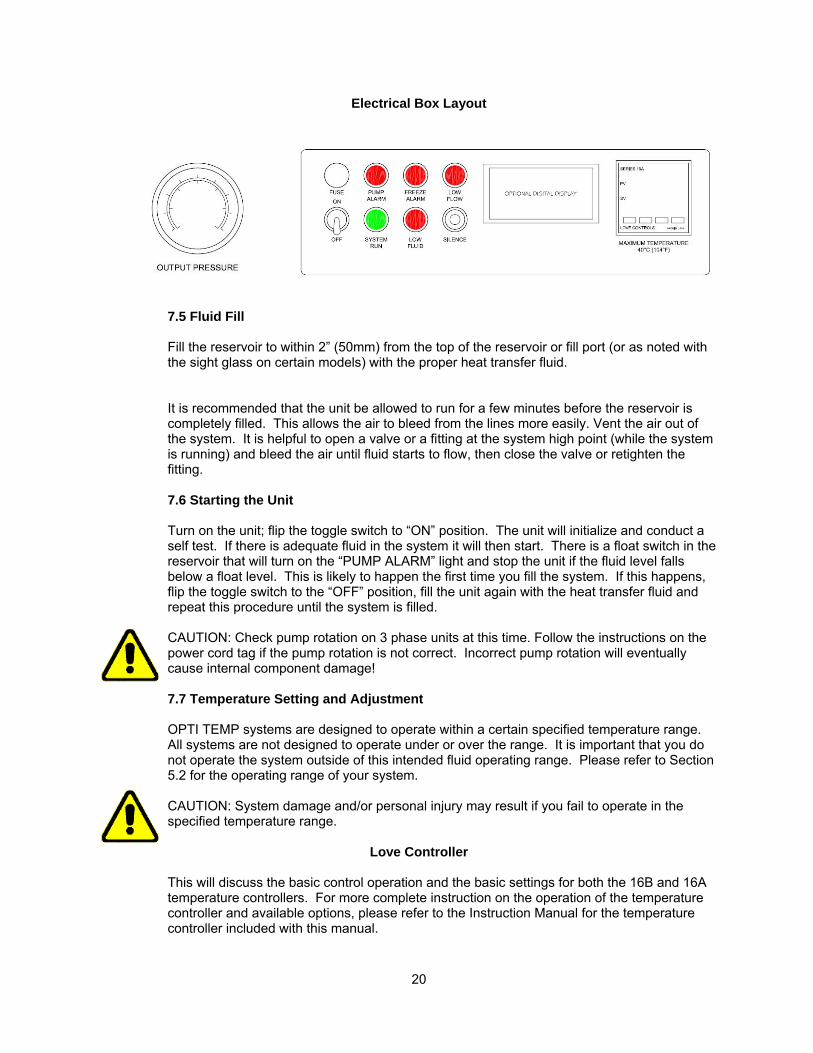
Electrical Box Layout
7.5 Fluid Fill Fill the reservoir to within 2” (50mm) from the top of the reservoir or fill port (or as noted with the sight glass on certain models) with the proper heat transfer fluid.
It is recommended that the unit be allowed to run for a few minutes before the reservoir is completely filled. This allows the air to bleed from the lines more easily. Vent the air out of the system. It is helpful to open a valve or a fitting at the system high point (while the system is running) and bleed the air until fluid starts to flow, then close the valve or retighten the fitting. 7.6 Starting the Unit Turn on the unit; flip the toggle switch to “ON” position. The unit will initialize and conduct a self test. If there is adequate fluid in the system it will then start. There is a float switch in the reservoir that will turn on the “PUMP ALARM” light and stop the unit if the fluid level falls below a float level. This is likely to happen the first time you fill the system. If this happens, flip the toggle switch to the “OFF” position, fill the unit again with the heat transfer fluid and repeat this procedure until the system is filled.
CAUTION: Check pump rotation on 3 phase units at this time. Follow the instructions on the power cord tag if the pump rotation is not correct. Incorrect pump rotation will eventually cause internal component damage! 7.7 Temperature Setting and Adjustment OPTI TEMP systems are designed to operate within a certain specified temperature range. All systems are not designed to operate under or over the range. It is important that you do not operate the system outside of this intended fluid operating range. Please refer to Section 5.2 for the operating range of your system. CAUTION: System damage and/or personal injury may result if you fail to operate in the specified temperature range.
Love Controller This will discuss the basic control operation and the basic settings for both the 16B and 16A temperature controllers. For more complete instruction on the operation of the temperature controller and available options, please refer to the Instruction Manual for the temperature controller included with this manual.
21
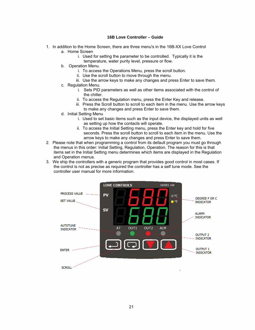
16B Love Controller – Guide
1. In addition to the Home Screen, there are three menu's in the 16B-XX Love Control
a. Home Screen i. Used for setting the parameter to be controlled. Typically it is the
temperature, water purity level, pressure or flow. b. Operation Menu.
i. To access the Operations Menu, press the scroll button. ii. Use the scroll button to move through the menu. iii. Use the arrow keys to make any changes and press Enter to save them.
c. Regulation Menu. i. Sets PID parameters as well as other items associated with the control of
the chiller. ii. To access the Regulation menu, press the Enter Key and release. iii. Press the Scroll button to scroll to each item in the menu. Use the arrow keys
to make any changes and press Enter to save them. d. Initial Setting Menu
i. Used to set basic items such as the input device, the displayed units as well as setting up how the contacts will operate.
ii. To access the Initial Setting menu, press the Enter key and hold for five seconds. Press the scroll button to scroll to each item in the menu. Use the arrow keys to make any changes and press Enter to save them.
2. Please note that when programming a control from its default program you must go through the menus in this order: Initial Setting, Regulation, Operation. The reason for this is that items set in the Initial Setting menu determines which items are displayed in the Regulation and Operation menus.
3. We ship the controllers with a generic program that provides good control in most cases. If the control is not as precise as required the controller has a self tune mode. See the controller user manual for more information.
22
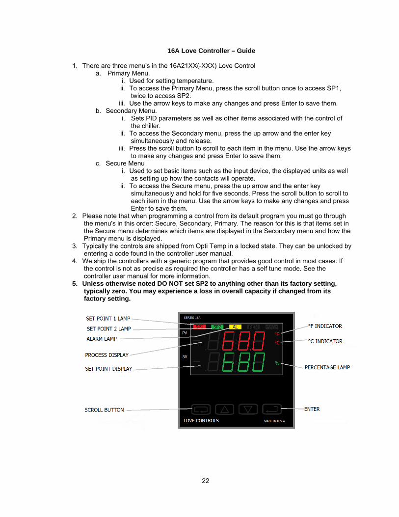
16A Love Controller – Guide
1. There are three menu's in the 16A21XX(-XXX) Love Control a. Primary Menu.
i. Used for setting temperature. ii. To access the Primary Menu, press the scroll button once to access SP1,
twice to access SP2. iii. Use the arrow keys to make any changes and press Enter to save them.
b. Secondary Menu. i. Sets PID parameters as well as other items associated with the control of
the chiller. ii. To access the Secondary menu, press the up arrow and the enter key
simultaneously and release. iii. Press the scroll button to scroll to each item in the menu. Use the arrow keys
to make any changes and press Enter to save them. c. Secure Menu
i. Used to set basic items such as the input device, the displayed units as well as setting up how the contacts will operate.
ii. To access the Secure menu, press the up arrow and the enter key simultaneously and hold for five seconds. Press the scroll button to scroll to each item in the menu. Use the arrow keys to make any changes and press Enter to save them.
2. Please note that when programming a control from its default program you must go through the menu's in this order: Secure, Secondary, Primary. The reason for this is that items set in the Secure menu determines which items are displayed in the Secondary menu and how the Primary menu is displayed.
3. Typically the controls are shipped from Opti Temp in a locked state. They can be unlocked by entering a code found in the controller user manual.
4. We ship the controllers with a generic program that provides good control in most cases. If the control is not as precise as required the controller has a self tune mode. See the controller user manual for more information.
5. Unless otherwise noted DO NOT set SP2 to anything other than its factory setting, typically zero. You may experience a loss in overall capacity if changed from its factory setting.

23
7.8 Fluid Bypass Valve Setting and Adjustment The chiller is equipped with a mechanical pressure-activated internal bypass valve. The bypass valve comes factory set. If you do not want to operate at the factory set pressure, or do not know what your operation pressure should be, start at a lower operation pressure. Reduce the pressure by loosening the lock ring and turning the bypass valve counterclockwise (unscrew outward) before starting the chiller. It may be necessary to remove an access cap on the bypass valve. With the chiller fully connected and running, read a pressure gage attached to your process fluid line and turn the bypass adjustment knob clockwise to reach your desired pressure. Tighten the lock ring when finished.
Bypass Set-Point Table
Standard Model OTC Standard Pump Pump ID Factory
Set-point
.25A, .33A, .5A,
.75A, 1.0A, 1.5A 1/3 HP motor and positive displacement pump
P1, P3
65 PSI
2.0A 1 HP motor and centrifugal pump
C2
45 PSI
3.0A
1.5 HP motor and centrifugal pump C3 55 PSI
NOTE: Refer to Page 31 for Pump Identification code. NOTE: Couplings and clamps are preferred to quick connect fittings because they have the potential for restricting the flow rate.
CAUTION: Please contact OPTI TEMP if your process is equipped with a valve, which may periodically interrupt flow to the process. Bypass settings may be critical to protect the system from damage! It is recommended that the valve in the supply line to the process be throttled (closed slowly) until the bypass valve just starts to feed. By putting your hand on the valve and bypass line you will be able to feel when the valve starts to open. This allows the air to be cleared from the bypass line.
7.9 System Fluid Drainage
1. Remove power from the unit. 2. Using the system drain connection (if applicable) open the petcock drain, located on the
unit and drain as much fluid as possible. 3. After the fluid system drain has been opened and fluid has left the unit, disconnect the
process connections from the chiller. 4. Drain any additional fluid out of the process connections. 5. Unscrew the filtration housings (if applicable) from their top and empty the fluid trapped
inside the filter housing. Screw back on the emptied filter housings. 6. Close the system drain, screw a cap on the process fluid connections and the system is
now ready for transport in warm climates.
Additional procedures for cold climate conditions: 1. Apply power back to the unit. 2. Add enough propylene glycol into the fluid reservoir to ensure the fluid tank level float is
met. Typically this requires > 25% of the fluid reservoir to be filled. 3. Connect a short-circuit loop hose to the process supply and process return connections.
24
4. Turn the unit on for approximately 30 seconds to ensure the propylene glycol has had a chance to contact all of the wetted internal components.
5. Turn off the chiller and remove power from the unit. 6. Open the system drain connection (if applicable). Drain as much fluid as possible. 7. Disconnect the process connections and allow any additional fluid to leave the unit. 8. Close the system drain and screw a cap on the process fluid connections. The unit is
now ready for transport in cold climates. Section 8 – Maintenance
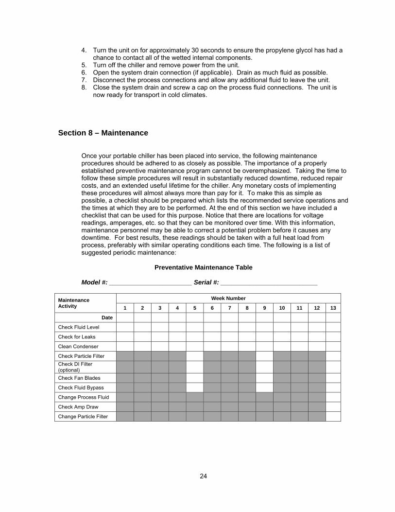
Once your portable chiller has been placed into service, the following maintenance procedures should be adhered to as closely as possible. The importance of a properly established preventive maintenance program cannot be overemphasized. Taking the time to follow these simple procedures will result in substantially reduced downtime, reduced repair costs, and an extended useful lifetime for the chiller. Any monetary costs of implementing these procedures will almost always more than pay for it. To make this as simple as possible, a checklist should be prepared which lists the recommended service operations and the times at which they are to be performed. At the end of this section we have included a checklist that can be used for this purpose. Notice that there are locations for voltage readings, amperages, etc. so that they can be monitored over time. With this information, maintenance personnel may be able to correct a potential problem before it causes any downtime. For best results, these readings should be taken with a full heat load from process, preferably with similar operating conditions each time. The following is a list of suggested periodic maintenance:
Preventative Maintenance Table
Model #: _______________________ Serial #: ___________________________ Maintenance Activity
Week Number
1 2 3 4 5 6 7 8 9 10 11 12 13
Date
Check Fluid Level
Check for Leaks
Clean Condenser
Check Particle Filter Check DI Filter (optional)
Check Fan Blades
Check Fluid Bypass
Change Process Fluid
Check Amp Draw
Change Particle Filter
25
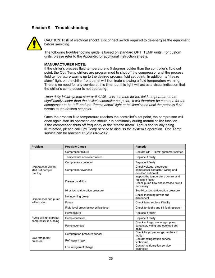
Section 9 – Troubleshooting
CAUTION: Risk of electrical shock! Disconnect switch required to de-energize the equipment before servicing. The following troubleshooting guide is based on standard OPTI TEMP units. For custom units, please refer to the Appendix for additional instruction sheets. MANUFACTURER NOTE: If the chiller’s process fluid temperature is 5 degrees colder than the controller’s fluid set point, the Opti Temp chillers are programmed to shut off the compressor until the process fluid temperature warms up to the desired process fluid set point. In addition, a “freeze alarm” light on the chiller front panel will illuminate showing a fluid temperature warning. There is no need for any service at this time, but this light will act as a visual indication that the chiller’s compressor is not operating. Upon daily initial system start or fluid fills, it is common for the fluid temperature to be significantly colder than the chiller’s controller set point. It will therefore be common for the compressor to be “off” and the “freeze alarm” light to be illuminated until the process fluid warms to the desired set point.
Once the process fluid temperature reaches the controller’s set point, the compressor will once again start its operation and should run continually during normal chiller function. If the compressor shuts off frequently or the “freeze alarm” light is continually being illuminated, please call Opti Temp service to discuss the system’s operation. Opti Temp service can be reached at (231)946-2931.
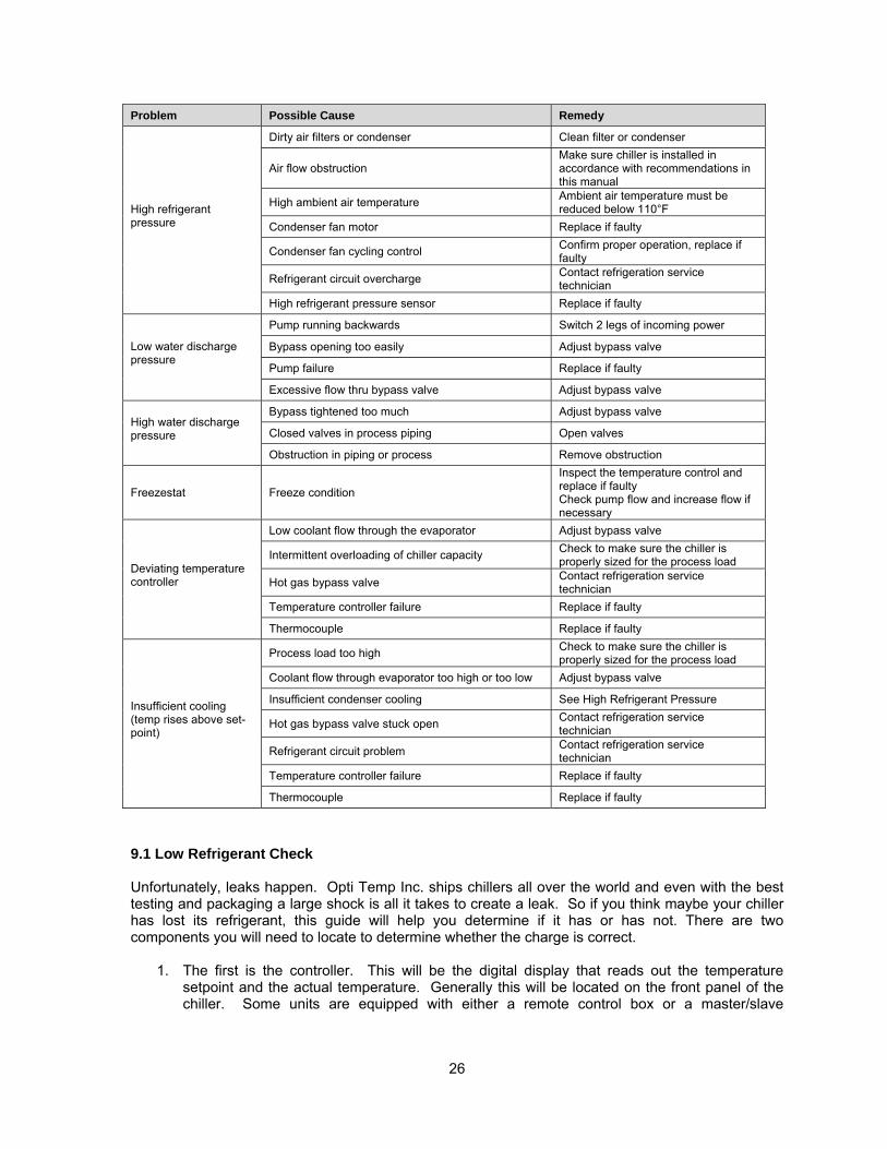
Problem Possible Cause Remedy
Compressor will not start but pump is running
Compressor failure Contact OPTI TEMP customer service
Temperature controller failure Replace if faulty
Compressor contactor Replace if faulty
Compressor overload Check voltage, amperage, compressor contactor, wiring and overload set-point
Freeze condition
Inspect the temperature control and replace if faulty Check pump flow and increase flow if necessary
Hi or low refrigeration pressure See Hi or low refrigeration pressure
Compressor and pump will not start
No incoming power Check incoming power and disconnect
Fuses Check fuse, replace if faulty
Fluid level drops below critical level Check for leaks and fill fluid reservoir
Pump will not start but compressor is running
Pump failure Replace if faulty
Pump contactor Replace if faulty
Pump overload Check voltage, amperage, pump contactor, wiring and overload set-point
Low refrigerant pressure
Refrigeration pressure sensor Check for proper range, replace if faulty
Refrigerant leak Contact refrigeration service technician
Low refrigerant charge Contact refrigeration service technician
26
Problem Possible Cause Remedy
High refrigerant pressure
Dirty air filters or condenser Clean filter or condenser
Air flow obstruction Make sure chiller is installed in accordance with recommendations in this manual
High ambient air temperature Ambient air temperature must be reduced below 110°F
Condenser fan motor Replace if faulty
Condenser fan cycling control Confirm proper operation, replace if faulty
Refrigerant circuit overcharge Contact refrigeration service technician
High refrigerant pressure sensor Replace if faulty
Low water discharge pressure
Pump running backwards Switch 2 legs of incoming power
Bypass opening too easily Adjust bypass valve
Pump failure Replace if faulty
Excessive flow thru bypass valve Adjust bypass valve
High water discharge pressure
Bypass tightened too much Adjust bypass valve
Closed valves in process piping Open valves
Obstruction in piping or process Remove obstruction
Freezestat Freeze condition
Inspect the temperature control and replace if faulty Check pump flow and increase flow if necessary
Deviating temperature controller
Low coolant flow through the evaporator Adjust bypass valve
Intermittent overloading of chiller capacity Check to make sure the chiller is properly sized for the process load
Hot gas bypass valve Contact refrigeration service technician
Temperature controller failure Replace if faulty
Thermocouple Replace if faulty
Insufficient cooling (temp rises above set-point)
Process load too high Check to make sure the chiller is properly sized for the process load
Coolant flow through evaporator too high or too low Adjust bypass valve
Insufficient condenser cooling See High Refrigerant Pressure
Hot gas bypass valve stuck open Contact refrigeration service technician
Refrigerant circuit problem Contact refrigeration service technician
Temperature controller failure Replace if faulty
Thermocouple Replace if faulty
9.1 Low Refrigerant Check Unfortunately, leaks happen. Opti Temp Inc. ships chillers all over the world and even with the best testing and packaging a large shock is all it takes to create a leak. So if you think maybe your chiller has lost its refrigerant, this guide will help you determine if it has or has not. There are two components you will need to locate to determine whether the charge is correct.
1. The first is the controller. This will be the digital display that reads out the temperature setpoint and the actual temperature. Generally this will be located on the front panel of the chiller. Some units are equipped with either a remote control box or a master/slave
27
arrangement with one controller on the unit and a second located remotely. In this case, set the Local/Remote switch to Local to make it easier to diagnose.
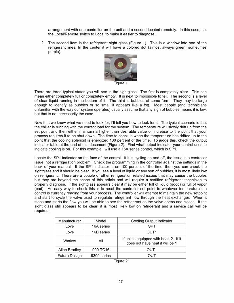
2. The second item is the refrigerant sight glass (Figure 1). This is a window into one of the refrigerant lines. In the center it will have a colored dot (almost always green, sometimes purple).
Figure 1
There are three typical states you will see in the sightglass. The first is completely clear. This can mean either completely full or completely empty. It is next to impossible to tell. The second is a level of clear liquid running in the bottom of it. The third is bubbles of some form. They may be large enough to identify as bubbles or so small it appears like a fog. Most people (and technicians unfamiliar with the way our system operates) usually assume that any sign of bubbles means it is low, but that is not necessarily the case. Now that we know what we need to look for, I’ll tell you how to look for it. The typical scenario is that the chiller is running with the correct load for the system. The temperature will slowly drift up from the set point and then either maintain a higher than desirable value or increase to the point that your process requires it to be shut down. The time to check is when the temperature has drifted up to the point that the cooling solenoid is energized 100 percent of the time. To judge this, check the output indicator table at the end of this document (Figure 2). Find what output indicator your control uses to indicate cooling is on. For this example I will use a 16A series control, which is SP1. Locate the SP1 indicator on the face of the control. If it is cycling on and off, the issue is a controller issue, not a refrigeration problem. Check the programming in the controller against the settings in the back of your manual. If the SP1 indicator is on 100 percent of the time, then you can check the sightglass and it should be clear. If you see a level of liquid or any sort of bubbles, it is most likely low on refrigerant. There are a couple of other refrigeration related issues that may cause the bubbles but they are beyond the scope of this article and will require a certified refrigerant technician to properly diagnose. If the sightglass appears clear it may be either full of liquid (good) or full of vapor (bad). An easy way to check this is to reset the controller set point to whatever temperature the control is currently reading from your process. The controller will attempt to maintain the new setpoint and start to cycle the valve used to regulate refrigerant flow through the heat exchanger. When it stops and starts the flow you will be able to see the refrigerant as the valve opens and closes. If the sight glass still appears to be clear, it is most likely low on refrigerant and a service call will be required.
Manufacturer Model Cooling Output Indicator Love 16A series SP1 Love 16B series OUT1
Watlow All If unit is equipped with heat, 2. If it does not have heat it will be 1
Allen Bradley 900-TC16 OUT1 Future Design 9300 series OUT
Figure 2
28
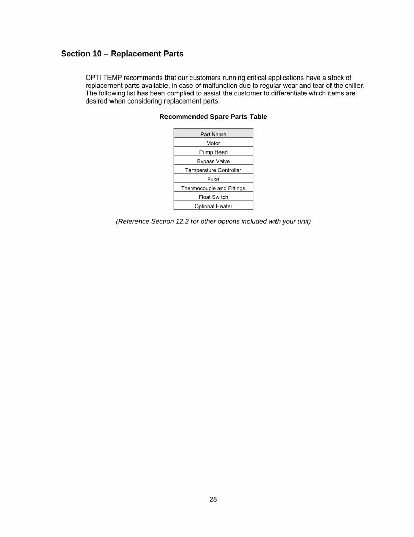
Section 10 – Replacement Parts
OPTI TEMP recommends that our customers running critical applications have a stock of replacement parts available, in case of malfunction due to regular wear and tear of the chiller. The following list has been complied to assist the customer to differentiate which items are desired when considering replacement parts.
Recommended Spare Parts Table
Part Name
Motor Pump Head
Bypass Valve Temperature Controller
Fuse Thermocouple and Fittings
Float Switch Optional Heater
(Reference Section 12.2 for other options included with your unit)

29
Section 11 – Warranty and Service
OPTI TEMP is committed to customer service both during and after the sale. If you have questions concerning the unit operation, please contact our customer service department at 231-946-2931 or [email protected]. OPTI TEMP systems are built to provide years of trouble free service. All systems are tested prior to shipping to insure you receive the highest quality product. In the unlikely event you experience problems, rest assured our technical service staff will be available to assist you resolve any problems quickly. If your unit fails to operate properly, or if you have questions concerning spare parts or service, contact our customer service department at 231-946-2931 or [email protected]. Before calling, please refer to the serial number tag to obtain the serial number:
Unit Serial Number ___________________________________
OPTI TEMP’s Standard Limited Warranty OPTI TEMP INC. warrants all equipment manufactured by it to be free from defects in workmanship and material when properly installed, operated, and maintained, in accordance with OPTI TEMP installation and operating guidelines, for a period of one year from the date of shipment to the original purchaser. The manufacturer’s obligation is strictly limited to the repair or replacement, at its option, any parts thereof which are returned to the factory, freight prepaid, during the warranty period and which upon inspection shall disclose to manufacturers satisfaction, to be defective. OPTI TEMP's liability does not include any labor charges for replacement of parts, adjustments, repairs, or any other work done outside its authorized repair facilities. OPTI TEMP's obligation to repair or replace shall not apply to any products which have been repaired or altered outside an OPTI TEMP authorized repair facility in any way, or which has been subject to negligence or misuse. OPTI TEMP’s liability does not include any resulting damage to persons, property, equipment, goods or merchandise arising out of any defect in, or failure of, its product, or by delays in shipment or delivery. The purchaser’s rights under this agreement may not be assigned to any other person or entity, expressly or by implication, without manufacturer’s prior written approval. The Warranty shall be deemed void if buyer fails to perform any of its obligations to seller. No claim of “breech of warranty” shall be cause for cancellation or rescission of the “contract of sale” for any system. The Company shall not be liable for failure to perform any obligation with respect to buyer resulting directly or indirectly from, or contributed to, by Acts of GOD; Acts of Buyer; Civil or Military Authority; Fires; Strikes or other Labor Disputes; Accidents; Floods; Epidemics; War; Riots; Delays in Transportation; Inability to Obtain Raw Materials, Components, Labor, Fuel or Supplies; Or Any Other Circumstance beyond the seller’s reasonable control whether similar or dissimilar to the foregoing. THE FOREGOING EXPRESS WARRANTY IS IN LIEU OF ALL OTHER WARRANTIES, EXPRESSED OR IMPLIED, INCLUDING BUT NOT LIMITED TO WARRANTIES OR MERCHANTABILITY AND FITNESS FOR A PARTICULAR PURPOSE. OPTI TEMP'S OBLIGATION UNDER THIS WARRANTY IS STRICTLY AND EXCLUSIVELY LIMITED TO THE REPAIR OR REPLACEMENT OF DEFECTIVE COMPONENT PARTS AND OPTI TEMP INC. DOES NOT ASSUME OR AUTHORIZE ANYONE TO ASSUME FOR IT ANY OTHER OBLIGATION. OPTI TEMP ASSUMES NO RESPONSIBILITY FOR INCIDENTAL, CONSEQUENTIAL, OR OTHER DAMAGES INCLUDING, BUT NOT LIMITED TO LOSS OR DAMAGE TO PROPERTY, LOSS OF PROFITS OR REVENUE, LOSS OF THE UNIT, LOSS OF TIME, OR INCONVENIENCE.
30
OPTI TEMP Service Policy OPTI TEMP's heat transfer equipment is designed to provide years of trouble free operation and is backed by a one year warranty. However, occasionally system repairs may be needed. To ensure timely resolution, OPTI TEMP has implemented the following service policy. Technical service and support assistance for OPTI TEMP re-circulating heat transfer systems is available free of charge by contacting the OPTI TEMP service department (located in the United States) by telephone at 231-946-2931 or by email at [email protected]. Emergency service/support is available 24 hours a day. Non-emergency calls or and email requests will generally be handled during normal business hours (8:00am to 5:00 pm eastern time). Telephone and or email diagnosis and troubleshooting can be difficult and may require a trial and error process. Please understand that OPTI TEMP can not assume any liability for misdiagnosis over the telephone. OPTI TEMP strongly encourages customers to take advantage of telephone support prior to returning a chiller to OPTI TEMP for evaluation. Often a problem with a chiller can be identified over the telephone and fixed quickly on site or may be an application or installation problem. By working with OPTI TEMP's service department to troubleshoot the system, you may be able to reduce downtime and expense associated with returning the equipment to our factory. Warranty and Non-Warranty Returns To return a product a “Return Material Authorization” (RMA) number must be obtained from OPTI TEMP. Our service department can be reached by emailing us at [email protected] or by calling 231-946-2931 during the hours of 8:00 am to 5:00 pm Eastern time. OPTI TEMP will require a model number, serial number, and a detailed description of the problem prior to assigning an RMA number. The RMA number should be clearly provided on the outside of the returned product packaging. Heat transfer systems must be returned clean, dry, and free from chemicals to OPTI TEMP's factory. Shipping costs must be prepaid. OPTI TEMP can not be responsible for any damage occurring during shipment to the factory. OPTI TEMP ordinarily will evaluate the unit within 3 to 5 business days of receipt and will use reasonable effort to repair the unit promptly, in most cases within one week of receiving all the required parts. If upon examination, it is determined that the problem is not due to a defect in materials or workmanship as defined by terms of the warranty, an evaluation fee will be charged according to the following schedule and a quotation provided for repair costs. 1. $375 for Models OTC-.25A through OTC-7.5A. 2. $575 for models OTC-7.5A through OTC-15A. 3. $775 for models OTC-20A and larger. The evaluation fee will be charged regardless of disposition (i.e.: scrap). If a non-warranty condition is known in advance of the return, a purchase order for the evaluation fee and return freight must be placed before the return is authorized. The chiller must be returned to OPTI TEMP with freight charges prepaid. OPTI TEMP will provide an estimate of the required repairs. After the repair OPTI TEMP will ship the chiller back freight collect. Debit memos should not be issued for warranty and non-warranty repairs unless the unit is returned as a result of an out-of-box (new) failure. OPTI TEMP will warranty the repair for
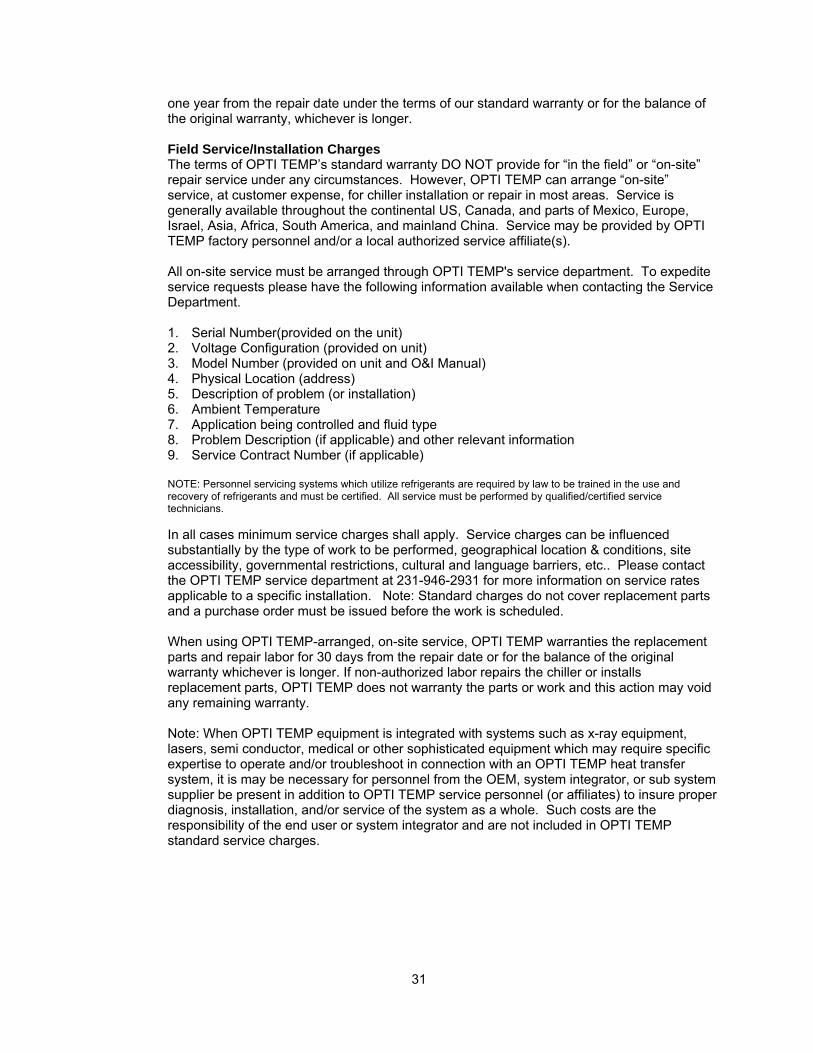
31
one year from the repair date under the terms of our standard warranty or for the balance of the original warranty, whichever is longer. Field Service/Installation Charges The terms of OPTI TEMP’s standard warranty DO NOT provide for “in the field” or “on-site” repair service under any circumstances. However, OPTI TEMP can arrange “on-site” service, at customer expense, for chiller installation or repair in most areas. Service is generally available throughout the continental US, Canada, and parts of Mexico, Europe, Israel, Asia, Africa, South America, and mainland China. Service may be provided by OPTI TEMP factory personnel and/or a local authorized service affiliate(s). All on-site service must be arranged through OPTI TEMP's service department. To expedite service requests please have the following information available when contacting the Service Department. 1. Serial Number(provided on the unit) 2. Voltage Configuration (provided on unit) 3. Model Number (provided on unit and O&I Manual) 4. Physical Location (address) 5. Description of problem (or installation) 6. Ambient Temperature 7. Application being controlled and fluid type 8. Problem Description (if applicable) and other relevant information 9. Service Contract Number (if applicable) NOTE: Personnel servicing systems which utilize refrigerants are required by law to be trained in the use and recovery of refrigerants and must be certified. All service must be performed by qualified/certified service technicians. In all cases minimum service charges shall apply. Service charges can be influenced substantially by the type of work to be performed, geographical location & conditions, site accessibility, governmental restrictions, cultural and language barriers, etc.. Please contact the OPTI TEMP service department at 231-946-2931 for more information on service rates applicable to a specific installation. Note: Standard charges do not cover replacement parts and a purchase order must be issued before the work is scheduled. When using OPTI TEMP-arranged, on-site service, OPTI TEMP warranties the replacement parts and repair labor for 30 days from the repair date or for the balance of the original warranty whichever is longer. If non-authorized labor repairs the chiller or installs replacement parts, OPTI TEMP does not warranty the parts or work and this action may void any remaining warranty. Note: When OPTI TEMP equipment is integrated with systems such as x-ray equipment, lasers, semi conductor, medical or other sophisticated equipment which may require specific expertise to operate and/or troubleshoot in connection with an OPTI TEMP heat transfer system, it is may be necessary for personnel from the OEM, system integrator, or sub system supplier be present in addition to OPTI TEMP service personnel (or affiliates) to insure proper diagnosis, installation, and/or service of the system as a whole. Such costs are the responsibility of the end user or system integrator and are not included in OPTI TEMP standard service charges.
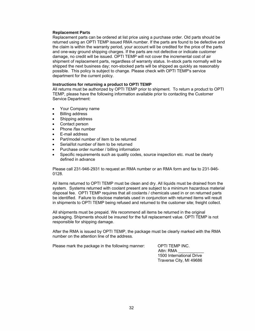
32
Replacement Parts Replacement parts can be ordered at list price using a purchase order. Old parts should be returned using an OPTI TEMP issued RMA number. If the parts are found to be defective and the claim is within the warranty period, your account will be credited for the price of the parts and one-way ground shipping charges. If the parts are not defective or indicate customer damage, no credit will be issued. OPTI TEMP will not cover the incremental cost of air shipment of replacement parts, regardless of warranty status. In-stock parts normally will be shipped the next business day; non-stocked parts will be shipped as quickly as reasonably possible. This policy is subject to change. Please check with OPTI TEMP's service department for the current policy. Instructions for returning a product to OPTI TEMP All returns must be authorized by OPTI TEMP prior to shipment. To return a product to OPTI TEMP, please have the following information available prior to contacting the Customer Service Department: • Your Company name • Billing address • Shipping address • Contact person • Phone /fax number • E-mail address • Part/model number of item to be returned • Serial/lot number of item to be returned • Purchase order number / billing information • Specific requirements such as quality codes, source inspection etc. must be clearly
defined in advance
Please call 231-946-2931 to request an RMA number or an RMA form and fax to 231-946-0128. All items returned to OPTI TEMP must be clean and dry. All liquids must be drained from the system. Systems returned with coolant present are subject to a minimum hazardous material disposal fee. OPTI TEMP requires that all coolants / chemicals used in or on returned parts be identified. Failure to disclose materials used in conjunction with returned items will result in shipments to OPTI TEMP being refused and returned to the customer site; freight collect. All shipments must be prepaid. We recommend all items be returned in the original packaging. Shipments should be insured for the full replacement value. OPTI TEMP is not responsible for shipping damage. After the RMA is issued by OPTI TEMP, the package must be clearly marked with the RMA number on the attention line of the address. Please mark the package in the following manner: OPTI TEMP INC. Attn: RMA ___________
1500 International Drive Traverse City, MI 49686
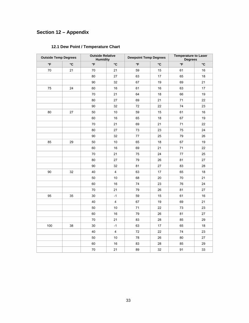
33
Section 12 – Appendix
12.1 Dew Point / Temperature Chart
Outside Temp Degrees Outside Relative Humidity Dewpoint Temp Degrees Temperature to Laser
Degrees °F °C °F °C °F °C °F °C
70 21 70 21 59 15 61 16
80 27 63 17 65 18
90 32 67 19 69 21
75 24 60 16 61 16 63 17
70 21 64 18 66 19
80 27 69 21 71 22
90 32 72 22 74 23
80 27 50 10 59 15 61 16
60 16 65 18 67 19
70 21 69 21 71 22
80 27 73 23 75 24
90 32 77 25 79 26
85 29 50 10 65 18 67 19
60 16 69 21 71 22
70 21 75 24 77 25
80 27 79 26 81 27
90 32 81 27 83 28
90 32 40 4 63 17 65 18
50 10 68 20 70 21
60 16 74 23 76 24
70 21 79 26 81 27
95 35 30 -1 59 15 61 16
40 4 67 19 69 21
50 10 71 22 73 23
60 16 79 26 81 27
70 21 83 28 85 29
100 38 30 -1 63 17 65 18
40 4 72 22 74 23
50 10 78 26 80 27
60 16 83 28 85 29
70 21 89 32 91 33
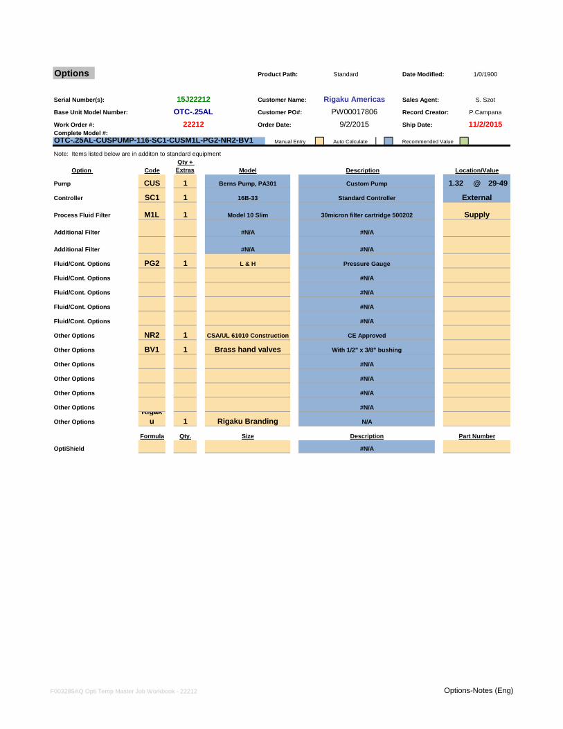
Options Product Path: Date Modified:
Serial Number(s): Customer Name: Sales Agent:
Base Unit Model Number: Customer PO#: Record Creator:
Work Order #: Order Date: Ship Date:Complete Model #:
Manual Entry Auto Calculate Recommended Value
Note: Items listed below are in additon to standard equipment
Process Fluid Filter
Additional Filter
Additional Filter
Fluid/Cont. Options
Fluid/Cont. Options
Fluid/Cont. Options
Fluid/Cont. Options
Fluid/Cont. Options
Other Options
Other Options
Other Options
Other Options
Other Options
Other Options
Other Options
OptiShield
PG2 1
#N/A
#N/A
Description Part NumberSizeQty.Formula
#N/A
Pressure Gauge
Custom Pump
Standard Controller
Qty + Extras Model
1
CUS
SC1
Code
Berns Pump, PA301
16B-33
1/0/1900Standard
1
External
Supply
Location/Value
OTC-.25AL-CUSPUMP-116-SC1-CUSM1L-PG2-NR2-BV1
29-49DescriptionOption
Controller
Pump
1M1L
15J22212 Rigaku Americas S. Szot
22212OTC-.25AL PW00017806 P.Campana
9/2/2015 11/2/2015
30micron filter cartridge 500202
#N/A
#N/A
#N/A
Model 10 Slim
L & H
#N/A
Rigaku 1 Rigaku Branding N/A
@1.32
#N/A
BV1 1 Brass hand valves With 1/2" x 3/8" bushing
#N/A
#N/A
#N/A
#N/A
NR2 1 CSA/UL 61010 Construction CE Approved
#N/A
F003285AQ Opti Temp Master Job Workbook - 22212 Options-Notes (Eng)
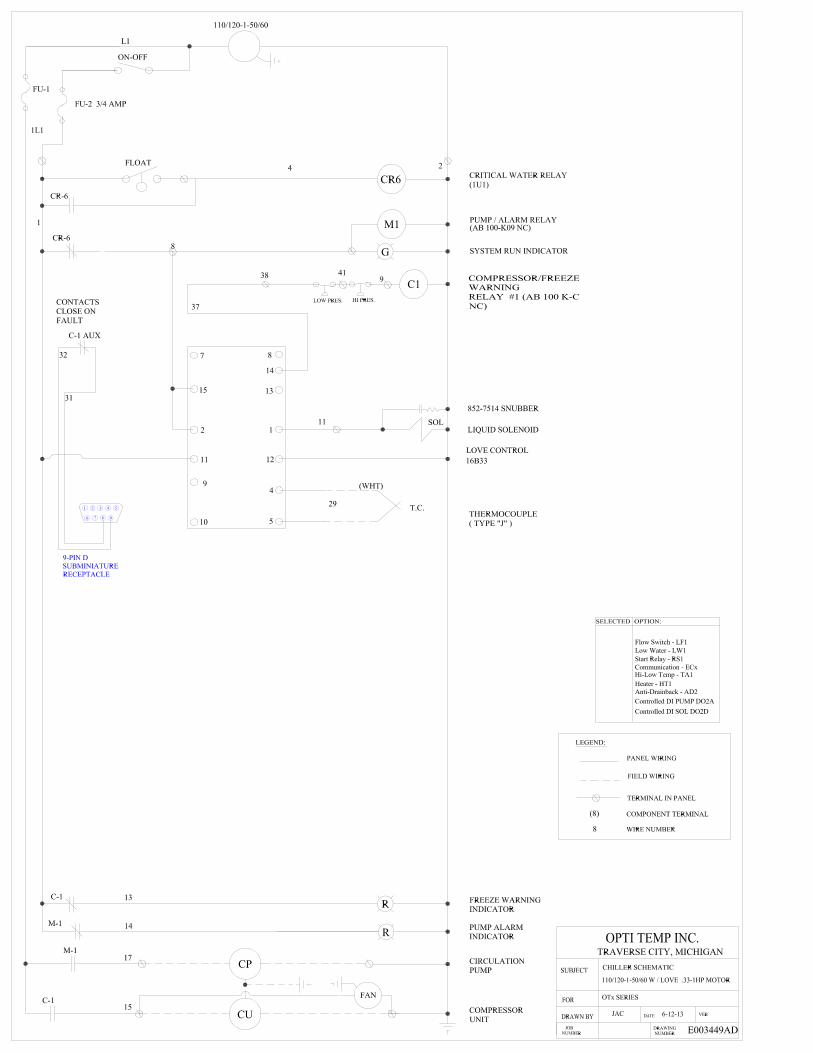
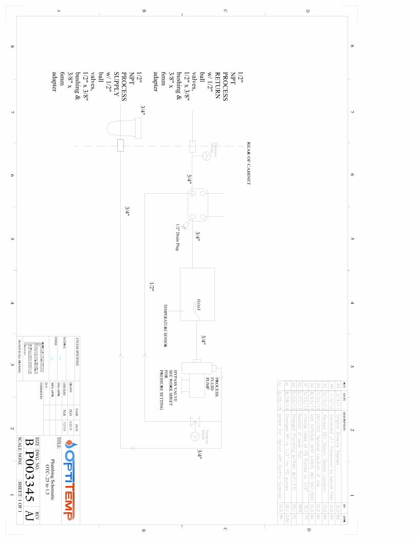
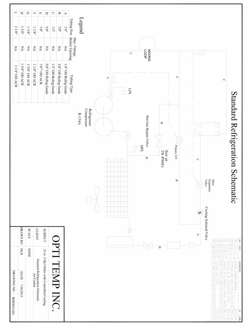
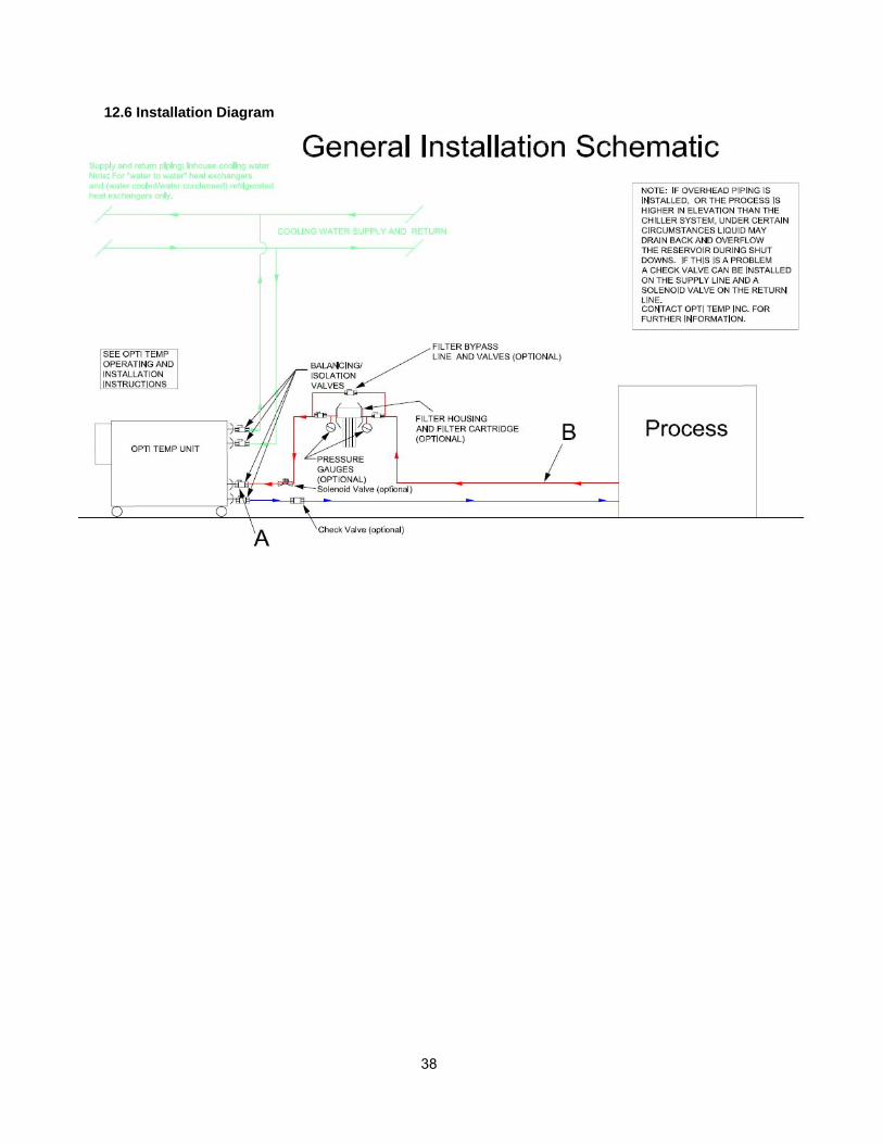
38
12.6 Installation Diagram
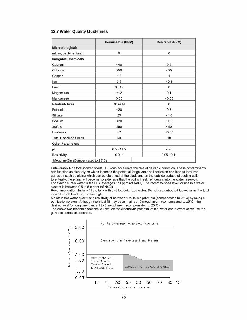
39
12.7 Water Quality Guidelines
Permissible (PPM) Desirable (PPM)
Microbiologicals
(algae, bacteria, fungi) 0 0
Inorganic Chemicals
Calcium <40 0.6
Chloride 250 <25
Copper 1.3 1
Iron 0.3 <0.1
Lead 0.015 0
Magnesium <12 0.1
Manganese 0.05 <0.03
Nitrates/Nitrites 10 as N 0
Potassium <20 0.3
Silicate 25 <1.0
Sodium <20 0.3
Sulfate 250 <50
Hardness 17 <0.05
Total Dissolved Solids 50 10
Other Parameters
pH 6.5 - 11.5 7 - 8
Resistivity 0.01* 0.05 - 0.1*
*Megohm-Cm (Compensated to 25°C)
Unfavorably high total ionized solids (TIS) can accelerate the rate of galvanic corrosion. These contaminants can function as electrolytes which increase the potential for galvanic cell corrosion and lead to localized corrosion such as pitting which can be observed at the studs and on the outside surface of cooling coils. Eventually, the pitting will become so extensive that the coil will leak refrigerant into the water reservoir. For example, raw water in the U.S. averages 171 ppm (of NaCl). The recommended level for use in a water system is between 0.5 to 5.0 ppm (of NaCl). Recommendation: Initially fill the tank with distilled/deionized water. Do not use untreated tap water as the total ionized solids level may be too high. Maintain this water quality at a resistivity of between 1 to 10 megohm-cm (compensated to 25°C) by using a purification system. Although the initial fill may be as high as 10 megohm-cm (compensated to 25°C), the desired level for long time usage 1 to 3 megohm-cm (compensated to 25°C). The above two recommendations will reduce the electrolytic potential of the water and prevent or reduce the galvanic corrosion observed.
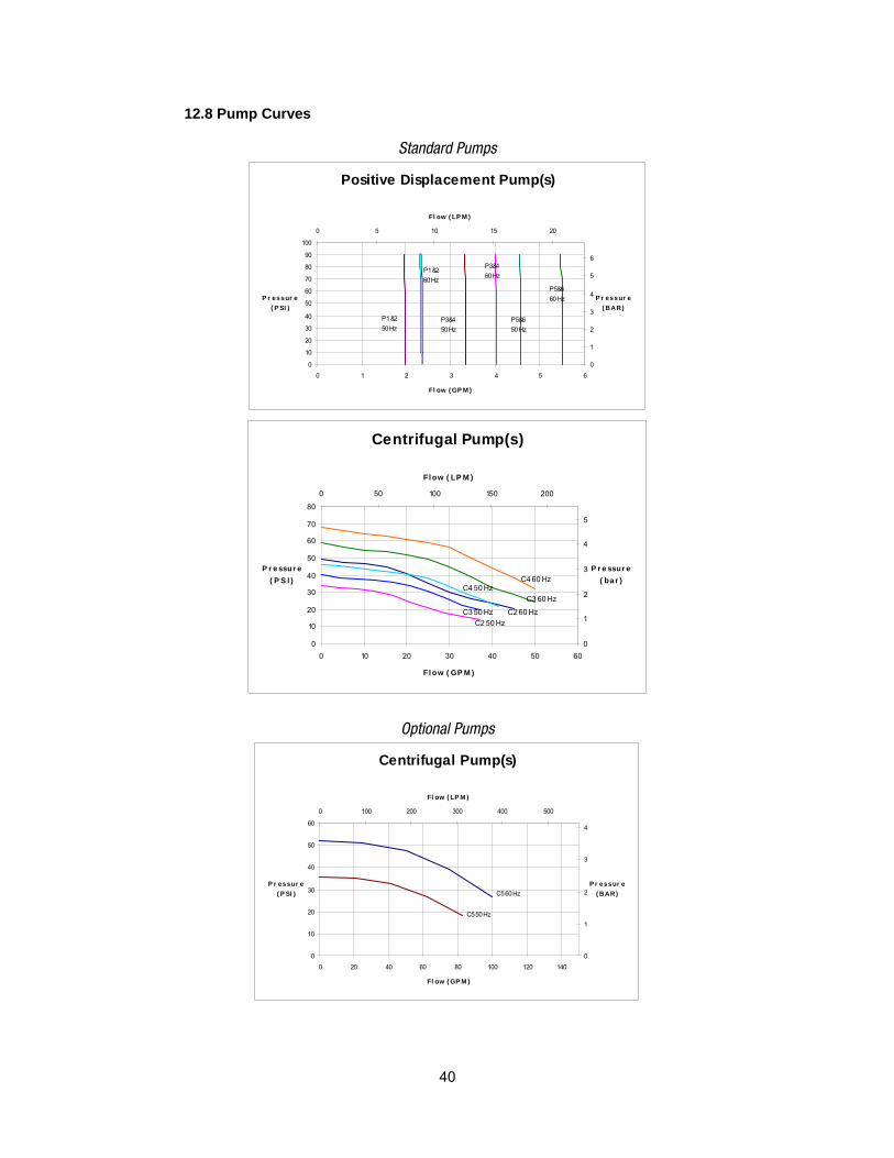
40
12.8 Pump Curves
Standard Pumps
Positive Displacement Pump(s)
0
10
20
30
40
50
60
70
80
90
100
0 1 2 3 4 5 6
Fl ow ( GP M )
P r essur e( P SI )
0
1
2
3
4
5
6
0 5 10 15 20
Fl ow ( LP M )
P r essur e( BAR)
P1 &260 Hz
P3&460 Hz
P5&660 Hz
P1 &250 Hz
P3&450 Hz
P5&650 Hz
Centrifugal Pump(s)
0
10
20
30
40
50
60
70
80
0 10 20 30 40 50 60
Fl ow ( GP M )
P r e ssur e ( P S I )
0
1
2
3
4
5
0 50 100 150 200
Fl ow ( LP M )
P r e ssur e ( ba r )
C3 60 Hz
C4 60 Hz
C3 50 Hz
C4 50 Hz
C2 60 HzC2 50 Hz
Optional Pumps
Centrifugal Pump(s)
0
10
20
30
40
50
60
0 20 40 60 80 100 120 140
Fl ow ( GP M )
P r essur e ( P SI )
0
1
2
3
4
0 100 200 300 400 500
Fl ow ( LP M )
P r essur e ( BAR)
C5 50 Hz
C5 60 Hz

41
Optional Pumps Continued
Regenerative Turbine Pump(s)
0
20
40
60
80
100
120
0 2 4 6 8 10 12
Flow (GPM)
Pressure (PSI)
0
5
10
15
20
0 5 10 15 20 25 30 35 40 45
Flow (LPM)
Pressure (BAR)
R5&660 Hz
R5&650 Hz
R1&250 Hz R1&2
60 HzR3&450 Hz
R3&460 Hz
Regerative Turbine Pump(s)
010
20304050
607080
90100
0 10 20 30 40 50
F l o w ( G P M )
P r e s s u r e
( P S I )
0
5
10
15
20
0 50 100 150
F l o w ( L P M )
P r e s s u r e
( B A R )
R7&8
50 Hz
R7&8
60 Hz
R9&0
50 Hz
R9&0
60 Hz
Mag Drive Pump(s)
010
20304050
607080
90100
0 2 4 6 8 10
F l o w ( G P M )
P r e s s u r e
( P S I )
0
1
2
3
4
5
6
0 10 20 30 40
F l o w ( L P M )
P r e s s u r e
( B A R )
M 2 50 Hz
M 2 60 Hz
Note: 1) Pump performance values are based on pump manufacturers published data. 2) Factors such as fluid temperature, fluid type, and external fluid circulating may impact pump performance values. 3) Reference "Specifications" for pump descriptions and horse power ratings. 4) Oversized pump selections may reduce chiller capacities. Consult applications for further details.
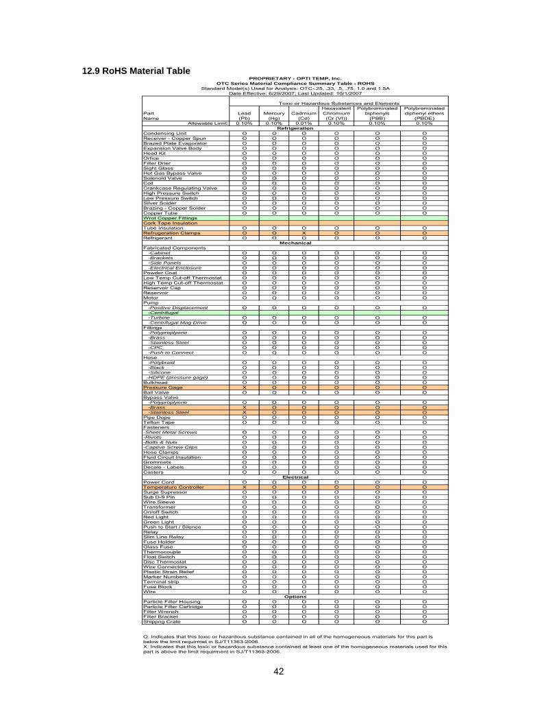
42
12.9 RoHS Material Table
Lead(Pb)
Mercury(Hg)
Cadmium(Cd)
HexavalentChromium(Cr (VI))
Polybrominated biphenyls
(PBB)
Polybrominated diphenyl ethers
(PBDE)Allowable Limit: 0.10% 0.10% 0.01% 0.10% 0.10% 0.10%
Condensing Unit O O O O O OReceiver - Copper Spun O O O O O OBrazed Plate Evaporator O O O O O OExpansion Valve Body O O O O O OHead Kit O O O O O OOrfice O O O O O OFilter Drier O O O O O OSight Glass O O O O O OHot Gas Bypass Valve O O O O O OSolenoid Valve O O O O O OCoil O O O O O OCrankcase Regulating Valve O O O O O OHigh Pressure Switch O O O O O OLow Pressure Switch O O O O O OSilver Solder O O O O O OBrazing - Copper Solder O O O O O OCopper Tube O O O O O OWrot Copper FittingsCork Tape InsulationTube Insulation O O O O O ORefrugeration Clamps O O X O O ORefrigerant O O O O O O
Fabricated Components -Cabinet O O O O O O -Brackets O O O O O O -Side Panels O O O O O O -Electrical Enclosure O O O O O OPowder Coat O O O O O OLow Temp Cut-off Thermostat O O O O O OHigh Temp Cut-off Thermostat O O O O O OReservoir Cap O O O O O OReservoir O O O O O OMotor O O O O O OPump -Positive Displacement O O O O O O -Centrifugal -Turbine O O O O O O -Centrifugal Mag Drive O O O O O OFittings -Polyproplyene O O O O O O -Brass O O O O O O -Stainless Steel O O O O O O -CPC O O O O O O -Push to Connect O O O O O OHose -Polybraid O O O O O O -Black O O O O O O -Silicone O O O O O O -HDPE (pressure gage) O O O O O OBulkhead O O O O O OPressure Gage X O O O O OBall Valve O O O O O OBypass Valve -Polyproplyene O O O O O O -Brass X O O O O O -Stainless Steel X O O O O OPipe Dope O O O O O OTeflon Tape O O O O O OFasteners-Sheet Metal Screws O O O O O O-Rivots O O O O O O-Bolts & Nuts O O O O O O-Captive Screw Clips O O O O O OHose Clamps O O O O O OFluid Circuit Insulation O O O O O OGrommets O O O O O ODecale - Labels O O O O O OCasters O O O O O O
Power Cord O O O O O OTemperature Controller X O O O O OSurge Supressor O O O O O OSub D-9 Pin O O O O O OWire Sleeve O O O O O OTransformer O O O O O OOn/off Switch O O O O O ORed Light O O O O O OGreen Light O O O O O OPush to Start / Silence O O O O O ORelay O O O O O OSlim Line Relay O O O O O OFuse Holder O O O O O OGlass Fuse O O O O O OThermocouple O O O O O OFloat Switch O O O O O ODisc Thermostat O O O O O OWire Connectors O O O O O OPlastic Strain Relief O O O O O OMarker Numbers O O O O O OTerminal strip O O O O O OFuse Block O O O O O OWire O O O O O O
Particle Filter Housing O O O O O OParticle Filter Cartridge O O O O O OFilter Wrench O O O O O OFilter Bracket O O O O O OShippng Crate O O O O O O
PROPRIETARY - OPTI TEMP, Inc.
X: Indicates that this toxic or hazardous substance contained at least one of the homogeneous materials used for this part is above the limit requirment in SJ/T11363-2006.
Toxic or Hazardous Substances and Elements
PartName
Options
OTC Series Material Compliance Summary Table - ROHSStandard Model(s) Used for Analysis: OTC-.25, .33, .5, .75, 1.0 and 1.5A
O: Indicates that this toxic or hazardous substance contained in all of the homogeneous materials for this part is below the limit requirmet in SJ/T11363-2006.
Refrigeration
Mechanical
Electrical
Date Effective: 6/29/2007; Last Updated: 10/1/2007
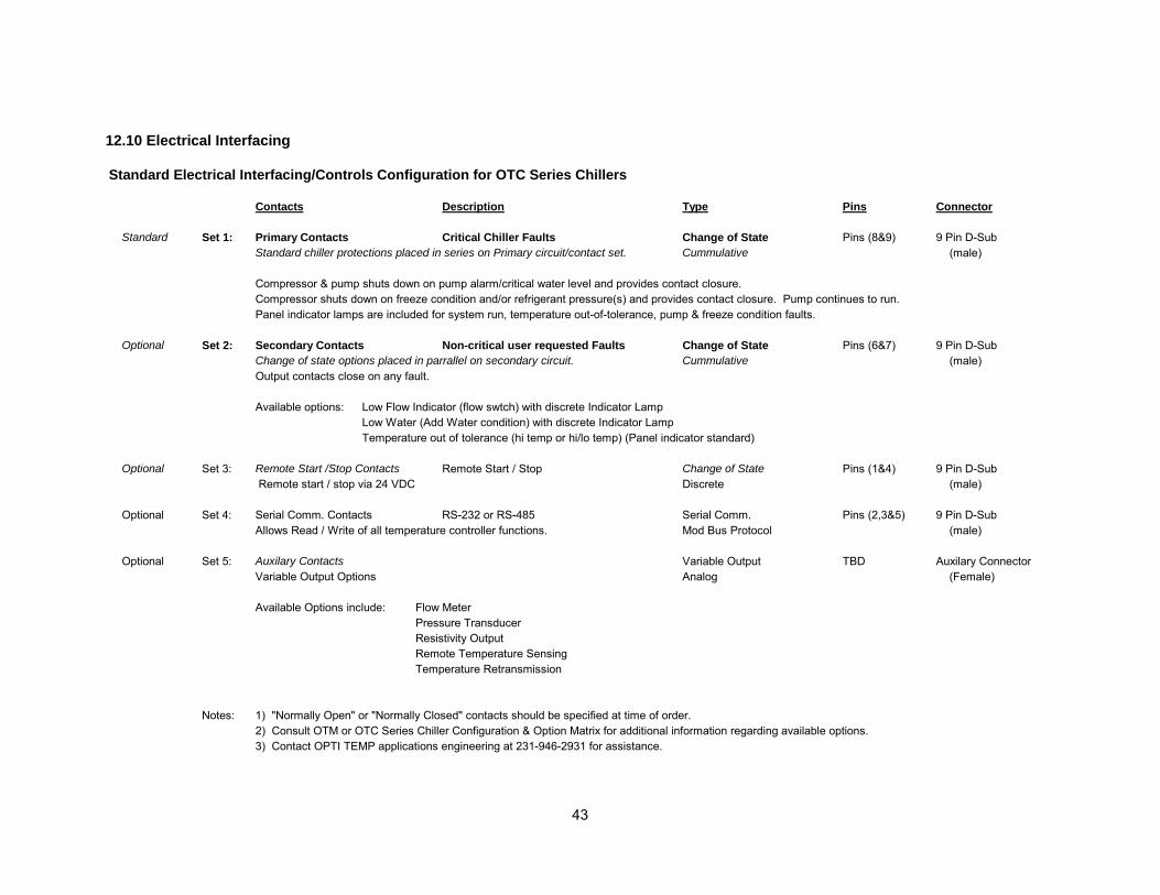
43
12.10 Electrical Interfacing Standard Electrical Interfacing/Controls Configuration for OTC Series Chillers
Contacts Description Type Pins Connector
Standard Set 1: Primary Contacts Critical Chiller Faults Change of State Pins (8&9) 9 Pin D-SubStandard chiller protections placed in series on Primary circuit/contact set. Cummulative (male)
Compressor & pump shuts down on pump alarm/critical water level and provides contact closure.Compressor shuts down on freeze condition and/or refrigerant pressure(s) and provides contact closure. Pump continues to run.Panel indicator lamps are included for system run, temperature out-of-tolerance, pump & freeze condition faults.
Optional Set 2: Secondary Contacts Non-critical user requested Faults Change of State Pins (6&7) 9 Pin D-SubChange of state options placed in parrallel on secondary circuit. Cummulative (male)Output contacts close on any fault.
Available options: Low Flow Indicator (flow swtch) with discrete Indicator LampLow Water (Add Water condition) with discrete Indicator LampTemperature out of tolerance (hi temp or hi/lo temp) (Panel indicator standard)
Optional Set 3: Remote Start /Stop Contacts Remote Start / Stop Change of State Pins (1&4) 9 Pin D-Sub Remote start / stop via 24 VDC Discrete (male)
Optional Set 4: Serial Comm. Contacts RS-232 or RS-485 Serial Comm. Pins (2,3&5) 9 Pin D-SubAllows Read / Write of all temperature controller functions. Mod Bus Protocol (male)
Optional Set 5: Auxilary Contacts Variable Output TBD Auxilary ConnectorVariable Output Options Analog (Female)
Available Options include: Flow MeterPressure TransducerResistivity OutputRemote Temperature SensingTemperature Retransmission
Notes: 1) "Normally Open" or "Normally Closed" contacts should be specified at time of order.2) Consult OTM or OTC Series Chiller Configuration & Option Matrix for additional information regarding available options.3) Contact OPTI TEMP applications engineering at 231-946-2931 for assistance.
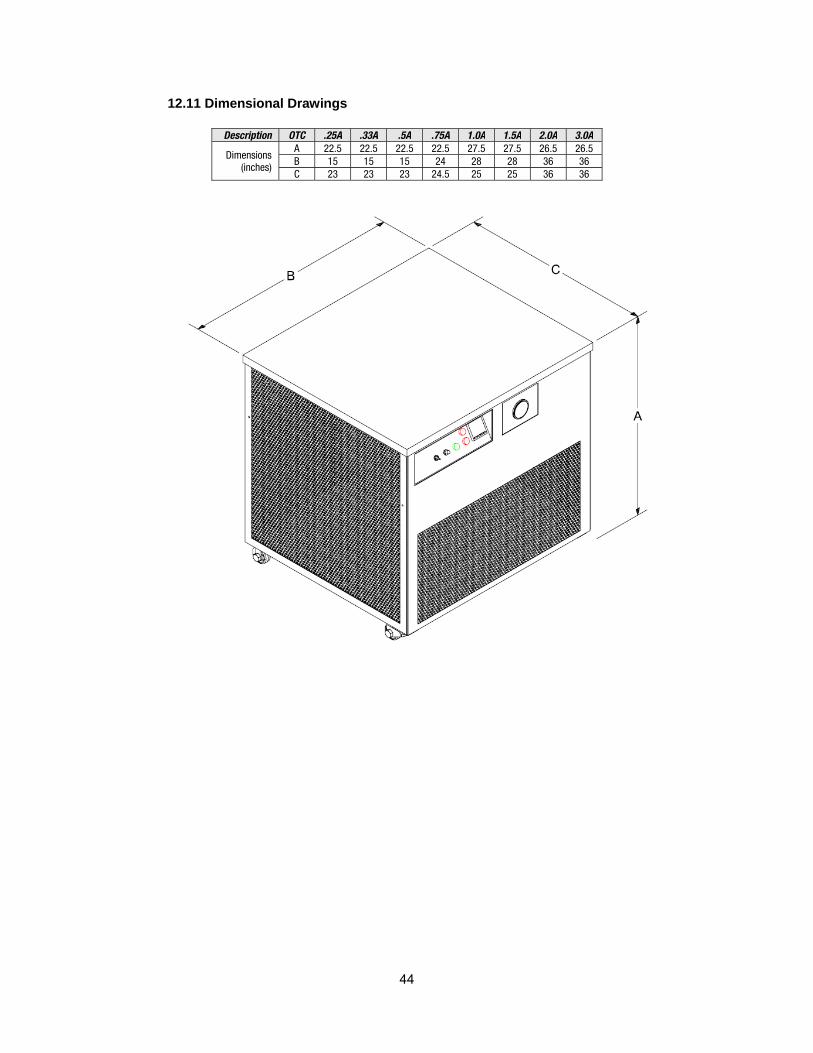
44
12.11 Dimensional Drawings
Description OTC .25A .33A .5A .75A 1.0A 1.5A 2.0A 3.0A
Dimensions (inches)
A 22.5 22.5 22.5 22.5 27.5 27.5 26.5 26.5 B 15 15 15 24 28 28 36 36 C 23 23 23 24.5 25 25 36 36

X003521AB.xlsx
X003521ABMenu Value °C Value °F Items in red optional
SV 20.0 70r-S rUn rUnSP 1 1
AL1H 0 0AL1L -3 -5AL2H 2 4AL2L 0 0AL3H 3 5AL3L 3 5LoC Off Off
OUT1 - -OUT2 - -
At Off OffPid0 0.0 0.0SV0 0.0 0.0P0 8 8I0 24 24d0 6 6
IoF0 55 55CLPD 4 4CoEF 1 1dEAd 0.0 0.0tPoF 0.0 0.0
InPt J JtPUn C FtP-H 40 104tP-L 7.0 45.0CtrL PiD PiD
S-HC COOL COOLALA1 11 11ALA2 12 12 HEATALA3 1 1 TOLERANCESALA oFF oFFCoSH oFF oFFC-SL ASCII ASCIIC-no 1 1bPS 9600 9600Len 7 7Prty EvEn EvEnStoP 1 1
Temperature Control
Operation Mode
Regulation Mode
Initial Setting
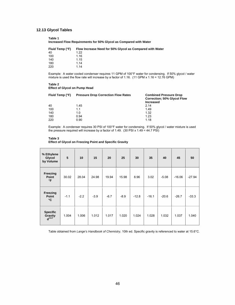
46
12.13 Glycol Tables Table 1 Increased Flow Requirements for 50% Glycol as Compared with Water Fluid Temp (°F) Flow Increase Need for 50% Glycol as Compared with Water 40 1.22 100 1.16 140 1.15 180 1.14 220 1.14
Example: A water cooled condenser requires 11 GPM of 100°F water for condensing. If 50% glycol / water mixture is used the flow rate will increase by a factor of 1.16. (11 GPM x 1.16 = 12.76 GPM)
Table 2 Effect of Glycol on Pump Head Fluid Temp (°F) Pressure Drop Correction Flow Rates Combined Pressure Drop
Correction; 50% Glycol Flow Increased
40 1.45 2.14 100 1.1 1.49 140 1.0 1.32 180 0.94 1.23 220 0.90 1.18 Example: A condenser requires 30 PSI of 100°F water for condensing. If 50% glycol / water mixture is used the pressure required will increase by a factor of 1.49. (30 PSI x 1.49 = 44.7 PSI) Table 3 Effect of Glycol on Freezing Point and Specific Gravity
% Ethylene Glycol
by Volume 5 10 15 20 25 30 35 40 45 50
Freezing Point
°F 30.02 28.04 24.98 19.94 15.98 8.96 3.02 -5.08 -16.06 -27.94
Freezing Point
°C -1.1 -2.2 -3.9 -6.7 -8.9 -12.8 -16.1 -20.6 -26.7 -33.3
Specific Gravity
d15.6° 1.004 1.006 1.012 1.017 1.020 1.024 1.028 1.032 1.037 1.040
Table obtained from Lange's Handbook of Chemistry, 10th ed. Specific gravity is referenced to water at 15.6°C.

47
12.14 Notes