Embed Size (px)
Citation preview
• Read this manual before installation and connection.Read the "Setting Manual" and "Operation Manual" included on the DVD-ROM that comes with the Master Station (IX-MV).
• Confi gure the system settings according to the "Setting Manual" after completing the installation and connection. The system will not function unless it has been properly confi gured.
• After installation, explain to the customer how to use the device, and be sure to provide the accompanying DVD-ROM that came with the Master Station (IX-MV).
Important• Perform the installation and connection only after fully understanding this device and the manual.Illustrations used in this manual may be different from the actual ones.
Mounting frameMain unit
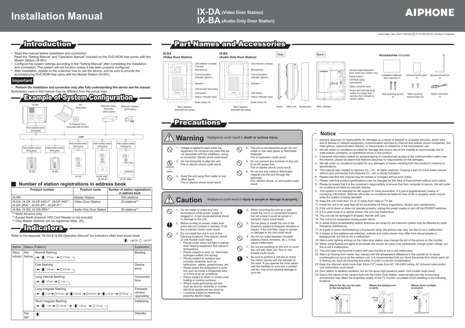
IX-DA(Video Door Station)
IX-BA(Audio Only Door Station)
Panel
Microphone
Communication indicator (green)
Speaker
Call indicator (orange)
Call button
CameraMicrophone
LED for night illumination
Communication indicator (green)
Speaker
Call indicator (orange)
Camera angle adjustment lever (Video Door Station only)
CAT5e/6 cable connections
Option connector input
Drain holes (4)
Status indicator (red)
Drain holes (4)
Status indicator (red)Call button
Accessories included
Installation Manual (this manual) x1
Option connector x1
Special screwdriver x1
Chinese RoHS paper x1
Wall mounting screws x2
Wall mounting wood screws x2
MAC address (beneath the panel)
MAC address (beneath the panel)
MAC address
Reset button*
* Press and hold the reset button for longer than 1 second, then release to restart station.
Side Back
Warning Negligence could result in death or serious injury.
1. Voltage is applied to parts within the equipment. Do not touch any parts that are not associated with the installation, wiring, or connection. Electric shock could result.
Dismantlingor
alteration
2. Do not dismantle or alter the unit.Fire or electric shock could result.
3. Keep the unit away from water or any other liquid.Fire or electric shock could result.
4. The unit is not explosion-proof. Do not install or use near gases or fl ammable materials. Fire or explosion could result.
5. Do not connect any terminal on the unit to an AC power line.Fire or electric shock could result.
6. Do not put any metal or fl ammable material into the unit through the openings.Fire, electric shock, or unit trouble could result.
Caution Negligence could result in injury to people or damage to property.
1. Do not install or make any wire terminations while power supply is plugged in. It can cause electrical shock or damage to the unit.
2. Before turning on power, make sure wires are not crossed or shorted. If not, fi re or electric shock could result.
3. Do not install the unit in any of the following locations. Fire, electric shock, or unit trouble could result. • Places under direct sunlight or places
near heating equipment that varies in temperature.
• Places subject to dust, oil, chemicals, hydrogen sulfi de (hot spring).
• Places subject to moisture and humidity extremes, such as bathrooms, cellars, greenhouses, etc.
• Places where the temperature is quite low, such as inside a refrigerated area or in front of an air conditioner.
• Places subject to steam or smoke (near heating or cooking surfaces).
• Where noise generating devices such as dimmer switches or inverter electrical appliances are close by.
• Locations subject to extremely powerful electric fi elds.
4. When mounting the unit on a wall, install the unit in a convenient location, but not where it could be jarred or bumped. Injury could result.
5. Do not place or install the unit in the locations subject to frequent vibration or impact. If the unit falls, injury to people or damage to the unit could result.
6. Do not run wires between movable objects (doors, windows, etc.). It may cause malfunction.
7. Do not put anything on the unit or cover the unit with cloth, etc. Fire or unit trouble could result.
8. Be sure to perform a call test or check the chime volume with the handset on the hook. If you operate the hook switch with the handset on your ear, a sudden call etc. may arrive causing damage to your ear.
Installation Manual IX-DA (Video Door Station)
IX-BA (Audio Only Door Station)
PrecautionsPrecautions
IntroductionIntroduction
Example of System Confi gurationExample of System Confi guration
IndicatorsIndicatorsRefer to the separate "IX-DA & IX-BA Operation Manual" for indicators other than those listed.
: Light ON : Light OFF
Name Status (Pattern) Explanation
Statusindicator
Redfl ashing
Normal fl ashing0.75 sec 0.75 sec
Booting
Fast fl ashing0.25 sec 0.25 sec
Device error
Long interval fl ashing0.5 sec 4 sec
Communication failure
Long irregular fl ashing1 sec 0.25 sec 0.25 sec0.25 sec 0.25 sec 0.25 sec
Firmwareversion upgrading
Short irregular fl ashing1 sec 0.25 sec0.25 sec 0.25 sec
Initializing
Redlight
Standby
Part Names and AccessoriesPart Names and Accessories
LAN
PoE-enabled switch(third party)
IX Support Tool (included with IX-MV)
PC (third party)
PoE-enabled switch(third party)
PoE-enabled switch(third party)
IX-BAIX-DA
IX-MV Network Video Recorder
(third party)
Network Camera (third party)
EMERGENCY
PoE-enabled switch(third party)
PoE-enabled switch(third party)
IX-DF-HID*1 IX-DF-P*2
IX-DF
PoE-enabled switch(third party)
IX-DF-2RA*1
Number of station registrations in address bookProduct number Product name Number of station registrations
in address bookIX-MV Master Station 500 stationsIX-DA, IX-DF, IX-DF-HID-I*1, IX-DF-HID*1, IX-DF-2RA*1, IX-DF-PI*2, IX-DF-P*2
Video Door Station 20 stations*3
IX-BA, IX-SS, IX-SS-2RA*1 Audio Only Door Station 20 stations*3
*1 North America only.*2 Except North America. HID Card Reader is not included.*3 Only Master Stations can be registered (Max. 20).
1. Aiphone assumes no responsibility for damages as a result of delayed or unusable services, which were due to failures in network equipment, communication services by Internet and cellular phone companies, line interruptions, communication failures, or inaccuracies or omissions in the transmission unit.
2. We will under no conditions be liable for damage that occurs due to the inability to communicate due to malfunctions, problems, or operational errors in this product.
3. If personal information leaked by eavesdropping or unauthorized access in the communication paths over the Internet, please be aware that Aiphone assumes no responsibility for the damages.
4. We will under no conditions be liable for any damages or losses resulting from this product’s contents or specifi cations.
5. This manual was created by Aiphone Co., Ltd., all rights reserved. Copying a part of or this entire manual without prior permission from Aiphone Co., Ltd. is strictly forbidden.
6. Please note that this manual may be revised or changed without prior notice.7. Please note that product specifi cations may be changed for the sake of improvement without prior notice.8. Please be aware that it is the customer’s responsibility to ensure that their computer is secure. We will under
no conditions be liable for security failures.9. This system is not intended for life support or crime prevention. It is just a supplementary means of
conveying information. Aiphone will under no conditions be liable for loss of life or property which occurs while the system is being operated.
10. Keep the unit more than 1m (3.3’) away from radio or TV set.11. Install the unit in an area that will be accessible for future inspections, repairs, and maintenance.12. If the unit is down or does not operate properly, unplug the power supply or turn off the POWER switches.13. If it is used close to a cellular phone, the unit may malfunction.14. The unit can be damaged if dropped. Handle with care.15. The unit turns inoperative during power failure.16. In areas where broadcasting station antennas are close by, the intercom system may be affected by radio
frequency interference.17. At a gate or porch illuminated by a fl uorescent lamp, the picture may vary, but this is not a malfunction.18. If stripes or fi ne patterns are refl ected, outlines and colors shown may differ from actual people or
backgrounds, but this is not a malfunction.19. Warm-color lighting shining on the video door station may change the tint of the picture on the monitor.20. When using fl uorescent lights to illuminate the screen its colors may periodically change (color rolling), but
this is not a malfunction.21. The unit case may become a warm with use, but this is not a unit malfunction.22. Warm air fl owing from inside may interact with the temperature difference in the outside air to cause
condensation to occur on the camera unit. It is recommended that you block the points from which warm air is fl owing out, such as incoming line ports, in order to prevent condensation.
23. Keep the intercom wires more than 30cm (12’’) away from AC 100-240V wiring. AC induced noise and/or unit malfunction could result.
24. Door station is weather-resistant, but do not spray high-pressure water. Unit trouble could result.25. Due to the nature of the camera built into the Video Door Station, external light and the surrounding
environment may affect the projection quality of the TV monitor, so please avoid installing in the following locations.
Where the backgroundis white
Where the sky can be seen in the background
Where direct sunlightis present
Sky White wall
Notice
Issue Date : Nov. 2014 FK2122 A P1114 SQ 56142 Printed in Thailand
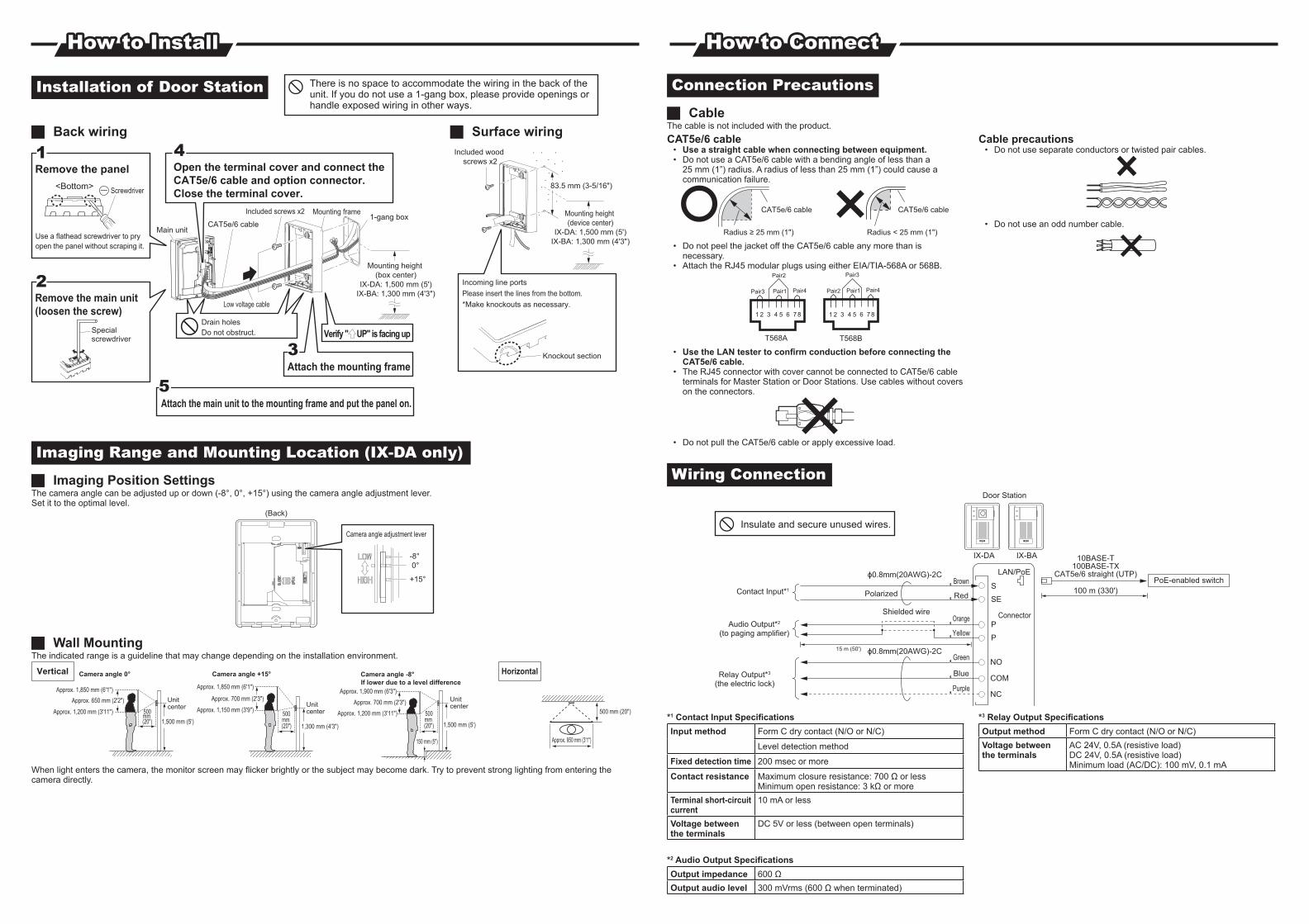
Installation of Door Station
Mounting frame
Attach the main unit to the mounting frame and put the panel on.
Attach the mounting frame
Verify " UP" is facing upDo not obstruct.Drain holes
Low voltage cable
1-gang box
Mounting height (box center)
IX-DA: 1,500 mm (5')IX-BA: 1,300 mm (4'3")
Included screws x2
45
23
4Open the terminal cover and connect the CAT5e/6 cable and option connector. Close the terminal cover.
CAT5e/6 cable
Remove the main unit (loosen the screw)
12
Special screwdriver
Knockout section
Remove the panel<Bottom> Screwdriver
11
Use a flathead screwdriver to pry open the panel without scraping it.
Main unit
Included wood screws x2
Incoming line portsPlease insert the lines from the bottom.*Make knockouts as necessary.
Mounting height (device center)
IX-DA: 1,500 mm (5')IX-BA: 1,300 mm (4'3")
83.5 mm (3-5/16")
Back wiring Surface wiring
Imaging Range and Mounting Location (IX-DA only)
Imaging Position SettingsThe camera angle can be adjusted up or down (-8°, 0°, +15°) using the camera angle adjustment lever.Set it to the optimal level.
Camera angle adjustment lever
+15°
0°-8°
(Back)
Wall MountingThe indicated range is a guideline that may change depending on the installation environment.
Unit center Unit
center
Unit center
Approx. 1,850 mm (6'1")Approx. 650 mm (2'2")
500mm (20")
500mm (20")
500mm (20")
Approx. 1,200 mm (3'11")1,500 mm (5')
Approx. 1,850 mm (6'1")
Approx. 700 mm (2'3")
Approx. 1,150 mm (3'9")
1,300 mm (4'3")
Approx. 1,900 mm (6'3")
Approx. 700 mm (2'3")
150 mm (5")
Approx. 1,200 mm (3'11")
1,500 mm (5')
Camera angle 0° Camera angle +15°If lower due to a level difference
HorizontalVertical Camera angle -8°
Approx. 950 mm (3'1")
500 mm (20")
When light enters the camera, the monitor screen may fl icker brightly or the subject may become dark. Try to prevent strong lighting from entering the camera directly.
Connection Precautions
CableThe cable is not included with the product.CAT5e/6 cable
• Use a straight cable when connecting between equipment.• Do not use a CAT5e/6 cable with a bending angle of less than a
25 mm (1”) radius. A radius of less than 25 mm (1”) could cause a communication failure.
CAT5e/6 cableCAT5e/6 cable
Radius ≥ 25 mm (1") Radius < 25 mm (1")
• Do not peel the jacket off the CAT5e/6 cable any more than is necessary.
• Attach the RJ45 modular plugs using either EIA/TIA-568A or 568B.
Pair4Pair3
Pair2
Pair1
T568A
Pair4Pair2
Pair3
Pair1
T568B
1 2 3 4 5 6 7 81 2 3 4 5 6 7 8
• Use the LAN tester to confi rm conduction before connecting the CAT5e/6 cable.
• The RJ45 connector with cover cannot be connected to CAT5e/6 cable terminals for Master Station or Door Stations. Use cables without covers on the connectors.
• Do not pull the CAT5e/6 cable or apply excessive load.
Cable precautions• Do not use separate conductors or twisted pair cables.
• Do not use an odd number cable.
Wiring Connection
IX-BAIX-DA
Door Station
Green
Purple
Blue
Brown
Red
Orange
Yellow
NO
LAN/PoE
10BASE-T100BASE-TX
CAT5e/6 straight (UTP)
Relay Output*3
(the electric lock)
Contact Input*1
Shielded wire
ϕ0.8mm(20AWG)-2C
ϕ0.8mm(20AWG)-2C
Polarized
PoE-enabled switch 100 m (330')
NC
COM
S
SE
P
P
Audio Output*2
(to paging amplifier)
15 m (50')
Connector
Insulate and secure unused wires.
*1 Contact Input Specifi cationsInput method Form C dry contact (N/O or N/C)
Level detection method
Fixed detection time 200 msec or more
Contact resistance Maximum closure resistance: 700 Ω or lessMinimum open resistance: 3 kΩ or more
Terminal short-circuit current
10 mA or less
Voltage between the terminals
DC 5V or less (between open terminals)
*2 Audio Output Specifi cationsOutput impedance 600 ΩOutput audio level 300 mVrms (600 Ω when terminated)
*3 Relay Output Specifi cationsOutput method Form C dry contact (N/O or N/C)Voltage between the terminals
AC 24V, 0.5A (resistive load)DC 24V, 0.5A (resistive load)Minimum load (AC/DC): 100 mV, 0.1 mA
How to InstallHow to Install How to ConnectHow to Connect
There is no space to accommodate the wiring in the back of the unit. If you do not use a 1-gang box, please provide openings or handle exposed wiring in other ways.