Embed Size (px)
Citation preview
7/29/2019 Aiphone Model AX Series - Install & Op Manual 0311- Westside Wholesale - Call 1-877-998-9378
http://slidepdf.com/reader/full/aiphone-model-ax-series-install-op-manual-0311-westside-wholesale-call 1/44
AX SERIES
Integrated Security & Communication System
INSTALLATION & OPERATION MANUA
0311
AX-248C
- 1 -
7/29/2019 Aiphone Model AX Series - Install & Op Manual 0311- Westside Wholesale - Call 1-877-998-9378
http://slidepdf.com/reader/full/aiphone-model-ax-series-install-op-manual-0311-westside-wholesale-call 2/44
- 2 -
General Prohibitions
General Precautions
Prohibition to Dismantle the Unit
Prohibition on Subjecting the Unit to Water
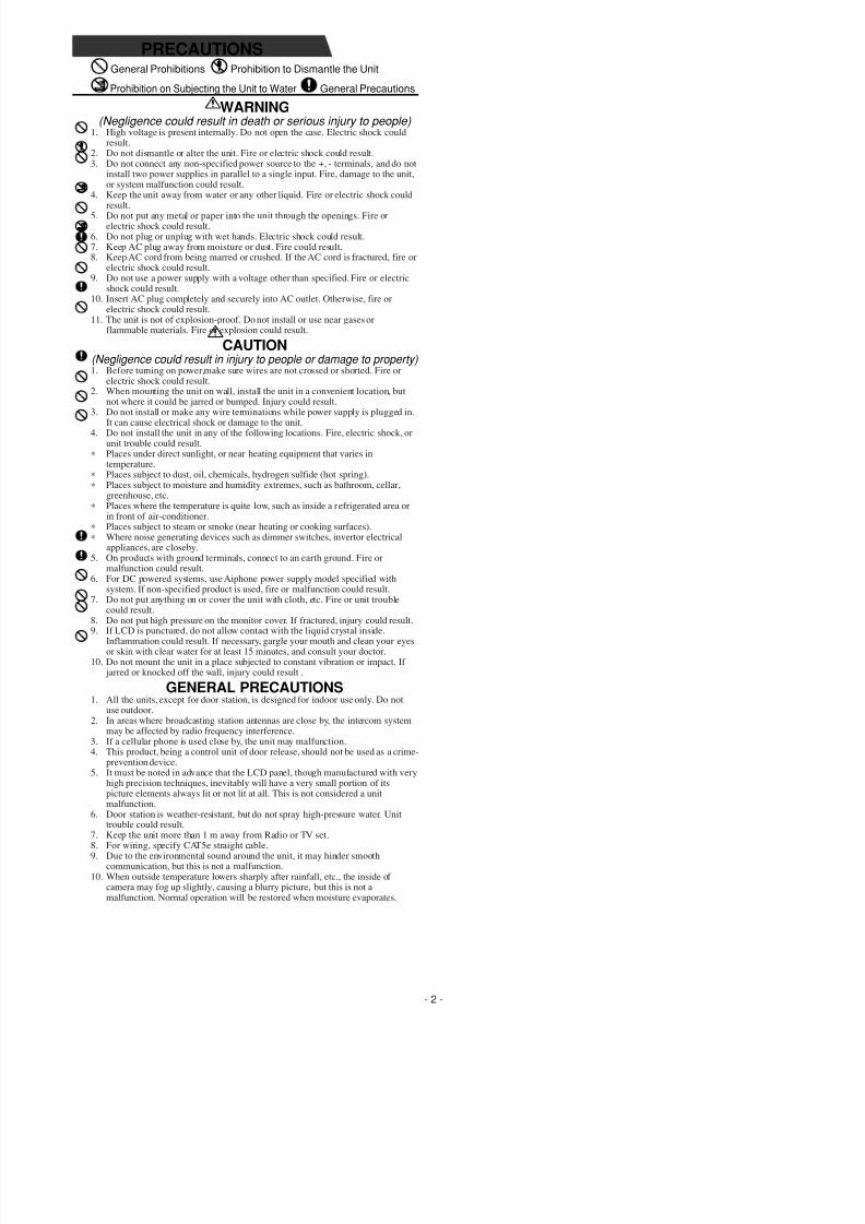
WARNING(Negligence could result in death or serious injury to people)
1. High voltage is present internally. Do not open the case. Electric shock couldresult.
2. Do not dismantle or alter the unit. Fire or electric shock could result.3. Do not connect any non-specified power source to the +, - terminals, and do not
install two power supplies in parallel to a single input. Fire, damage to the unit,or system malfunction could result.
4. Keep the unit away from water or any other liquid. Fire or electric shock couldresult.5. Do not put any metal or paper into the unit through the openings. Fire or
electric shock could result.6. Do not plug or unplug with wet hands. Electric shock could result.7. Keep AC plug away from moisture or dust. Fire could result.8. Keep AC cord from being marred or crushed. If the AC cord is fractured, fire or
electric shock could result.9. Do not use a power supply with a voltage other than specified. Fire or electric
shock could result.10. Insert AC plug completely and securely into AC outlet. Otherwise, fire or
electric shock could result.11. The unit is not of explosion-proof. Do not install or use near gases or
flammable materials. Fire or explosion could result.
CAUTION(Negligence could result in injury to people or damage to property)1. Before turning on power,make sure wires are not crossed or shorted. Fire or
electric shock could result.2. When mounting the unit on wall, install the unit in a convenient location, but
not where it could be jarred or bumped. Injury could result.3. Do not install or make any wire terminations while power supply is plugged in.
It can cause electrical shock or damage to the unit.4. Do not install the unit in any of the following locations. Fire, electric shock, or
unit trouble could result.∗ Places under direct sunlight, or near heating equipment that varies in
temperature.∗ Places subject to dust, oil, chemicals, hydrogen sulfide (hot spring).∗ Places subject to moisture and humidity extremes, such as bathroom, cellar,
greenhouse, etc.∗ Places where the temperature is quite low, such as inside a refrigerated area or
in front of air-conditioner.∗ Places subject to steam or smoke (near heating or cooking surfaces).∗ Where noise generating devices such as dimmer switches, invertor electrical
appliances, are closeby.5. On products with ground terminals, connect to an earth ground. Fire or
malfunction could result.6. For DC powered systems, use Aiphone power supply model specified with
system. If non-specified product is used, fire or malfunction could result.7. Do not put anything on or cover the unit with cloth, etc. Fire or unit trouble
could result.8. Do not put high pressure on the monitor cover. If fractured, injury could result.9. If LCD is punctured, do not allow contact with the liquid crystal inside.
Inflammation could result. If necessary, gargle your mouth and clean your eyesor skin with clear water for at least 15 minutes, and consult your doctor.
10. Do not mount the unit in a place subjected to constant vibration or impact. If jarred or knocked off the wall, injury could result .
GENERAL PRECAUTIONS1. All the units, except for door station, is designed for indoor use only. Do not
use outdoor.2. In areas where broadcasting station antennas are close by, the intercom system
may be affected by radio frequency interference.3. If a cellular phone is used close by, the unit may malfunction.4. This product, being a control unit of door release, should not be used as a crime-
prevention device.5. It must be noted in advance that the LCD panel, though manufactured with very
high precision techniques, inevitably will have a very small portion of its
picture elements always lit or not lit at all. This is not considered a unitmalfunction.6. Door station is weather-resistant, but do not spray high-pressure water. Unit
trouble could result.7. Keep the unit more than 1 m away from Radio or TV set.8. For wiring, specify CAT5e straight cable.9. Due to the environmental sound around the unit, it may hinder smooth
communication, but this is not a malfunction.10. When outside temperature lowers sharply after rainfall, etc., the inside of
camera may fog up slightly, causing a blurry picture, but this is not amalfunction. Normal operation will be restored when moisture evaporates.
PRECAUTIONS
7/29/2019 Aiphone Model AX Series - Install & Op Manual 0311- Westside Wholesale - Call 1-877-998-9378
http://slidepdf.com/reader/full/aiphone-model-ax-series-install-op-manual-0311-westside-wholesale-call 3/44
- 3 -
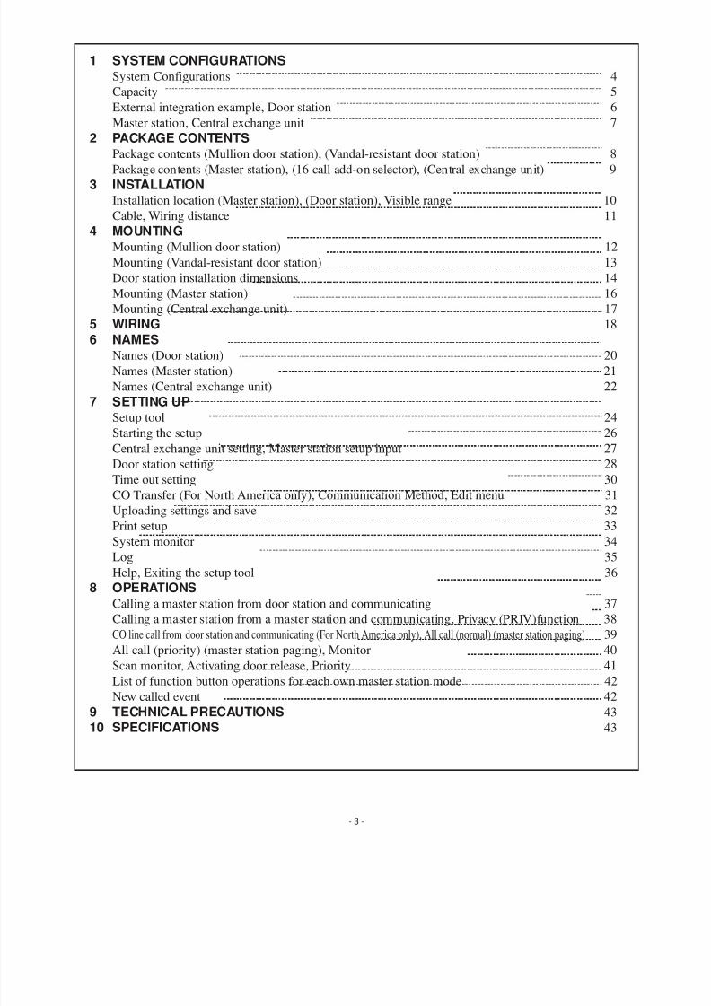
1 SYSTEM CONFIGURATIONSSystem Configurations 4Capacity 5
External integration example, Door station 6
Master station, Central exchange unit 7
2 PACKAGE CONTENTSPackage contents (Mullion door station), (Vandal-resistant door station) 8
Package contents (Master station), (16 call add-on selector), (Central exchange unit) 9
3 INSTALLATIONInstallation location (Master station), (Door station), Visible range 10
Cable, Wiring distance 11
4 MOUNTINGMounting (Mullion door station) 12
Mounting (Vandal-resistant door station) 13
Door station installation dimensions 14
Mounting (Master station) 16Mounting (Central exchange unit) 17
5 WIRING 186 NAMES
Names (Door station) 20
Names (Master station) 21
Names (Central exchange unit) 22
7 SETTING UPSetup tool 24
Starting the setup 26
Central exchange unit setting, Master station setup input 27
Door station setting 28
Time out setting 30
CO Transfer (For North America only), Communication Method, Edit menu 31Uploading settings and save 32
Print setup 33
System monitor 34
Log 35
Help, Exiting the setup tool 36
8 OPERATIONSCalling a master station from door station and communicating 37Calling a master station from a master station and communicating, Privacy (PRIV)function 38
CO line call from door station and communicating (For North America only), All call (normal) (master station paging) 39
All call (priority) (master station paging), Monitor 40Scan monitor, Activating door release, Priority 41
List of function button operations for each own master station mode 42
New called event 42
9 TECHNICAL PRECAUTIONS 43
10 SPECIFICATIONS 43
7/29/2019 Aiphone Model AX Series - Install & Op Manual 0311- Westside Wholesale - Call 1-877-998-9378
http://slidepdf.com/reader/full/aiphone-model-ax-series-install-op-manual-0311-westside-wholesale-call 4/44
- 4 -
1 SYSTEM CONFIGURATIONS
[1]
[1]
Max. 8
Max. 24
Max. 120
PS
[2]
[2]
[6][3]DC 24 V 2 A
DC 24 V 2 A
[4]
[5]
Max. 4
Max. 8
Max. 32
Max. 32
Max. 32
PS
PS
[6][3]
[4]
[5]
PS
C A T 5 e
M a x . 3 0 0 m
C A T 5 e
M a x . 3 0 0 m
C A T 5 e
M a x . 3 0 0 m
C A T 5 e
M a x . 3 0 0 m
C A T 5 e
M a x . 3 0 0 m
C A T 5 e
M a x . 3 0 0 m
C A T 5 e
M a x . 3 0 0 m
C A T 5 e
M a x . 3 0 0 m
C A T 5 e
M a x . 3 0 0 m
CAT5e
C A T 5 e
M a x . 3 0 0 m
C A T 5 e
M a x . 3 0 0 m
C A T 5 e
M a x . 3 0 0 m
R S - 2 3 2 C
M a x . 1 5 m
C A T 5 e
M a x . 3 0 0 m
C A T 5 e
M a x . 3 0 0 m
R S - 2 3 2 C
M a x . 1 5 m
CAT5e
CAT5e
AX-084C
AX-248C
AX-320C
AX-320C
AX-320C
DC 24 V 2 A
DC 24 V 2 A
1-1

7/29/2019 Aiphone Model AX Series - Install & Op Manual 0311- Westside Wholesale - Call 1-877-998-9378
http://slidepdf.com/reader/full/aiphone-model-ax-series-install-op-manual-0311-westside-wholesale-call 5/44
- 5 -
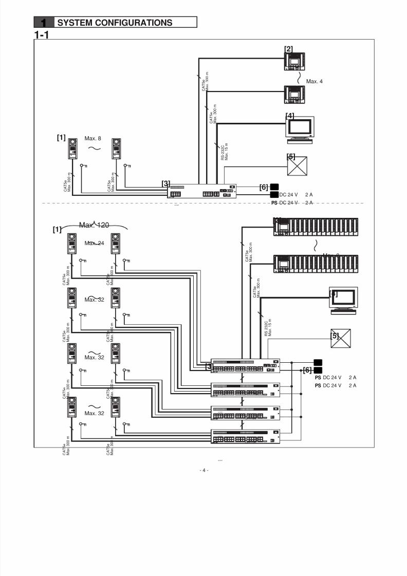
1-1 1-2System Configurations
[1] Door station[2] Master station• A maximum of seven 16-call add-on selectors (AX-16SW) can
be connected.[3] Central Exchange Unit
• A maximum of three Add-on exchange units (AX-320C) can beconnected.
[4] PC
[5] Other external connections• Access control system• CCTV system• CO line adaptor
• Video output[6] Power supply x2
Capacity• Door station: Maximum 120 stations
(When AX-248C x1, AX-320C x3 use• Master station: Maximum 4 stations
(when AX-084C used)Maximum 8 stations
(when AX-248C used)• Power supply: PS-2420UL (DC 24 V, 2 A)
PS-2420S (DC 24 V, 2 A)
PS-2420DIN (DC 24 V, 2 A)For audio x1, for video x1
• Number of talk paths: 2• Number of video paths: 2
• All call: 1• Video monitor: 2 (same as talk paths and video paths)
• Scan monitor: 1
7/29/2019 Aiphone Model AX Series - Install & Op Manual 0311- Westside Wholesale - Call 1-877-998-9378
http://slidepdf.com/reader/full/aiphone-model-ax-series-install-op-manual-0311-westside-wholesale-call 6/44
1-4
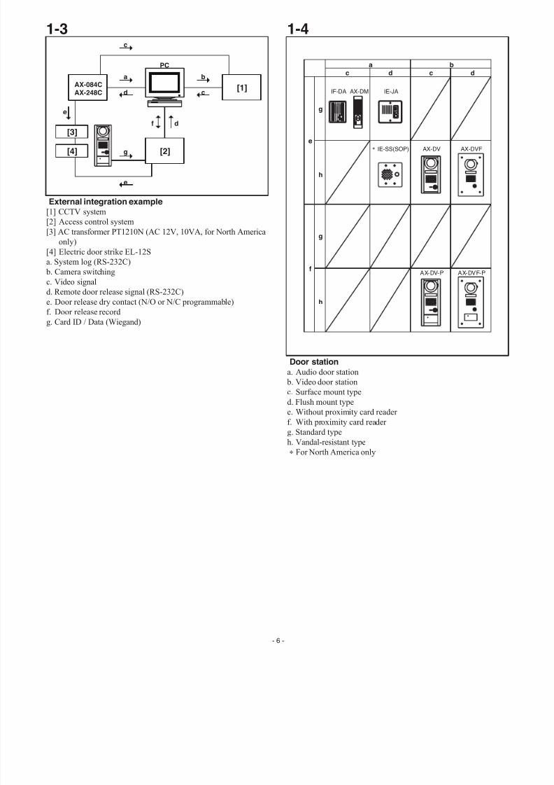
Door station
a. Audio door station
b. Video door stationc. Surface mount type
d. Flush mount type
e. Without proximity card reader
f. With proximity card reader
g. Standard type
h. Vandal-resistant type
∗ For North America only
1-3
External integration example[1] CCTV system
[2] Access control system
[3] AC transformer PT1210N (AC 12V, 10VA, for North America
only)
[4] Electric door strike EL-12Sa. System log (RS-232C)
b. Camera switching
c. Video signal
d. Remote door release signal (RS-232C)
e. Door release dry contact (N/O or N/C programmable)
f. Door release record
g. Card ID / Data (Wiegand)
[1]
[2]
[3]
[4]
PC
AX-084CAX-248C
c
a
d
b
c
e
g
e
f d
AX-DM IE-JA
IE-SS(SOP) AX-DV AX-DVF
AX-DV-P AX-DVF-P
IF-DA
a
c d c d
b
e
f
g
h
g
h
- 6 -
7/29/2019 Aiphone Model AX Series - Install & Op Manual 0311- Westside Wholesale - Call 1-877-998-9378
http://slidepdf.com/reader/full/aiphone-model-ax-series-install-op-manual-0311-westside-wholesale-call 7/44
- 7 -
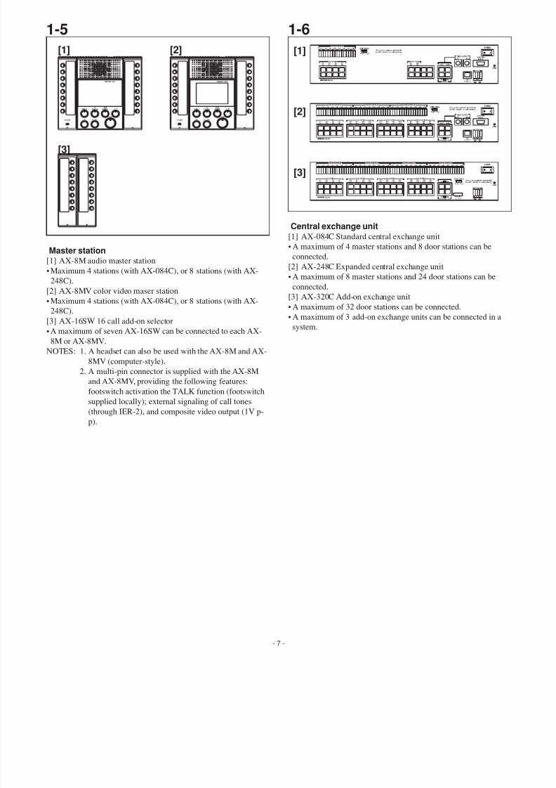
1-6
Central exchange unit[1] AX-084C Standard central exchange unit
• A maximum of 4 master stations and 8 door stations can be
connected.[2] AX-248C Expanded central exchange unit
• A maximum of 8 master stations and 24 door stations can be
connected.
[3] AX-320C Add-on exchange unit
• A maximum of 32 door stations can be connected.
• A maximum of 3 add-on exchange units can be connected in a
system.
1-5
Master station[1] AX-8M audio master station
•Maximum 4 stations (with AX-084C), or 8 stations (with AX-
248C).
[2] AX-8MV color video maser station
•Maximum 4 stations (with AX-084C), or 8 stations (with AX-
248C).
[3] AX-16SW 16 call add-on selector
•A maximum of seven AX-16SW can be connected to each AX-
8M or AX-8MV.
NOTES: 1. A headset can also be used with the AX-8M and AX-
8MV (computer-style).
2. A multi-pin connector is supplied with the AX-8M
and AX-8MV, providing the following features:footswitch activation the TALK function (footswitch
supplied locally); external signaling of call tones
(through IER-2), and composite video output (1V p-
p).
[1] [2]
[3]
[1]
[2]
[3]
7/29/2019 Aiphone Model AX Series - Install & Op Manual 0311- Westside Wholesale - Call 1-877-998-9378
http://slidepdf.com/reader/full/aiphone-model-ax-series-install-op-manual-0311-westside-wholesale-call 8/44
- 8 -
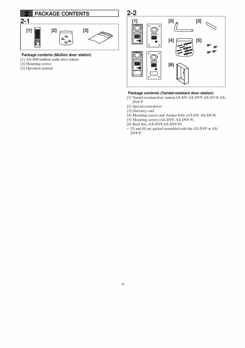
2-2
Package contents (Vandal-resistant door station)[1] Vandal-resistant door station AX-DV, AX-DVF, AX-DV-P, A
DVF-P
[2] Special screwdriver
[3] Directory card
[4] Mounting screws and Anchor bolts (AX-DV, AX-DV-P)
[5] Mounting screws (AX-DVF, AX-DVF-P)
[6] Back box (AX-DVF,AX-DVF-P)
∗ [5] and [6] are packed assembled with the AX-DVF or AX-
DVF-P.
2 PACKAGE CONTENTS
2-1
Package contents (Mullion door station)[1] AX-DM mullion audio door station
[2] Mounting screws
[3] Operation manual
[1] [2] [3]
[1] [2] [3]
[4]
[6]
[5]
7/29/2019 Aiphone Model AX Series - Install & Op Manual 0311- Westside Wholesale - Call 1-877-998-9378
http://slidepdf.com/reader/full/aiphone-model-ax-series-install-op-manual-0311-westside-wholesale-call 9/44
- 9 -
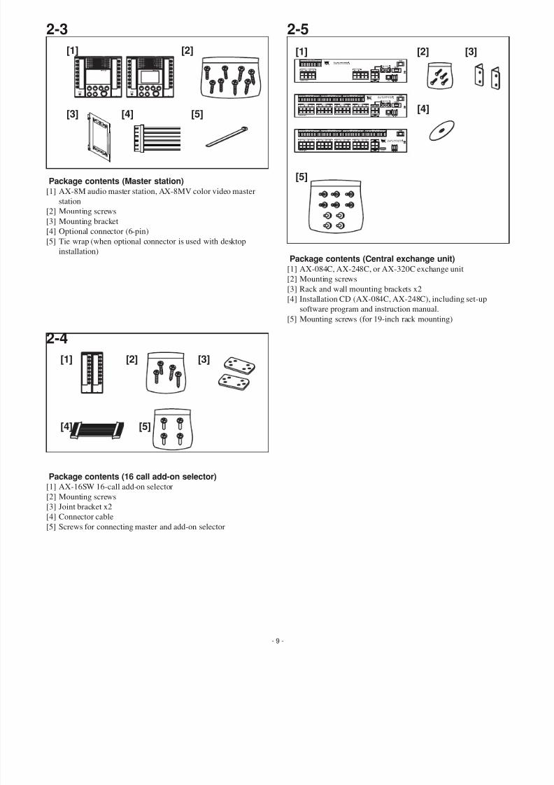
2-4
Package contents (16 call add-on selector)[1] AX-16SW 16-call add-on selector
[2] Mounting screws
[3] Joint bracket x2[4] Connector cable
[5] Screws for connecting master and add-on selector
2-3
Package contents (Master station)[1] AX-8M audio master station, AX-8MV color video master
station
[2] Mounting screws
[3] Mounting bracket
[4] Optional connector (6-pin)
[5] Tie wrap (when optional connector is used with desktop
installation)
2-5
Package contents (Central exchange unit)[1] AX-084C, AX-248C, or AX-320C exchange unit
[2] Mounting screws
[3] Rack and wall mounting brackets x2
[4] Installation CD (AX-084C, AX-248C), including set-up
software program and instruction manual.
[5] Mounting screws (for 19-inch rack mounting)
[1] [2]
[3] [5][4]
[1] [2] [3]
[4] [5]
[1] [2] [3]
[4]
[5]
7/29/2019 Aiphone Model AX Series - Install & Op Manual 0311- Westside Wholesale - Call 1-877-998-9378
http://slidepdf.com/reader/full/aiphone-model-ax-series-install-op-manual-0311-westside-wholesale-call 10/44
- 10 -
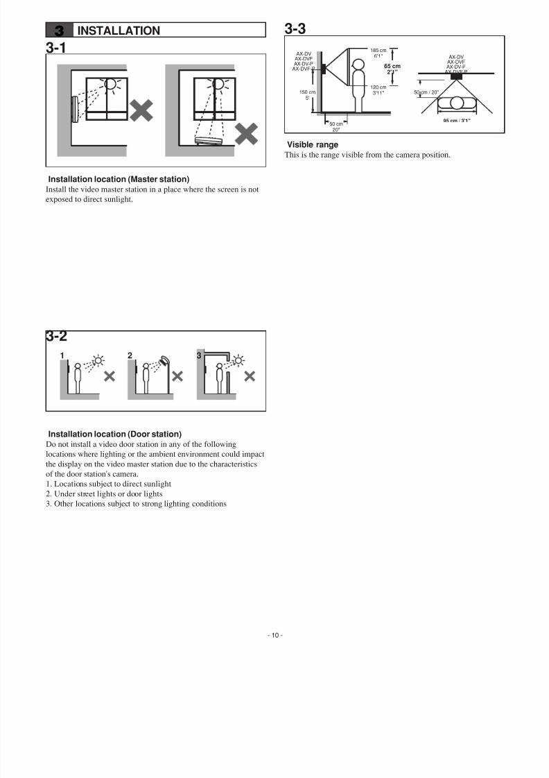
3-1
Installation location (Master station)Install the video master station in a place where the screen is not
exposed to direct sunlight.
3 INSTALLATION
3-2
Installation location (Door station)Do not install a video door station in any of the following
locations where lighting or the ambient environment could impact
the display on the video master station due to the characteristics
of the door station's camera.
1. Locations subject to direct sunlight
2. Under street lights or door lights
3. Other locations subject to strong lighting conditions
3-3
Visible rangeThis is the range visible from the camera position.
1 2 3
65 cm2'1"
150 cm5'
50 cm20"
50 cm / 20"
AX-DVAX-DVFAX-DV-P
AX-DVF-P
95 cm / 3'1"
185 cm6'1"
120 cm3'11"
AX-DVAX-DVFAX-DV-P
AX-DVF-P
7/29/2019 Aiphone Model AX Series - Install & Op Manual 0311- Westside Wholesale - Call 1-877-998-9378
http://slidepdf.com/reader/full/aiphone-model-ax-series-install-op-manual-0311-westside-wholesale-call 11/44
- 11 -
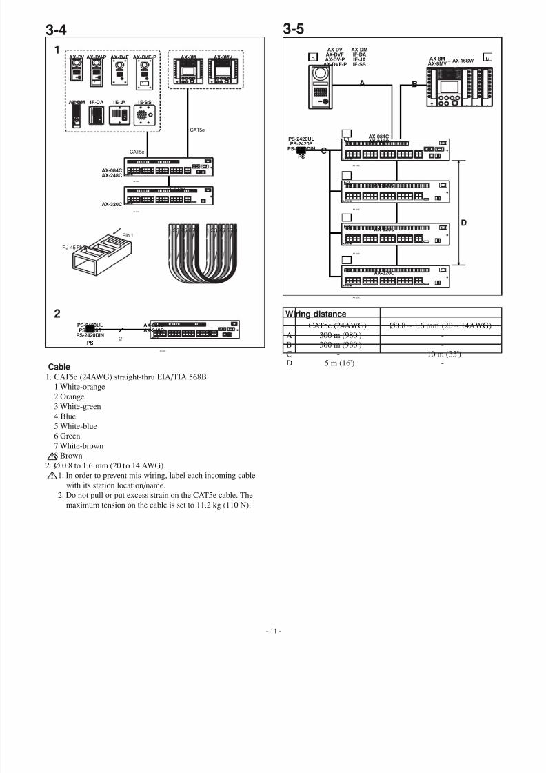
3-5
Wiring distance
3-4
Cable
1. CAT5e (24AWG) straight-thru EIA/TIA 568B1 White-orange
2 Orange
3 White-green
4 Blue
5 White-blue
6 Green
7 White-brown
8 Brown
2. Ø 0.8 to 1.6 mm (20 to 14 AWG)
1. In order to prevent mis-wiring, label each incoming cable
with its station location/name.
2. Do not pull or put excess strain on the CAT5e cable. The
maximum tension on the cable is set to 11.2 kg (110 N).
AX-DMIF-DAIE-JAIE-SS
AX-DVAX-DVFAX-DV-P
AX-DVF-P
AX-320C
AX-320C
AX-084CAX-248C
+ AX-16SW MD
E1
E4
E2
AX-320C
E3
A B
C
AX-8MAX-8MV
PS-2420ULPS-2420S
PS-2420DIN
PS
D
AX-248C
AX-320C
AX-320C
AX-320C
RJ-45 Plug
Pin 11 23 45 67 8 1 23 45 67 8
1
2
CAT5e
CAT5e
CAT5e
2
AX-DM IF-DA
AX-DV AX-DV-P AX-DVF AX-DVF-P
AX-320C
AX-084CAX-248C
PS-2420ULPS-2420S
PS-2420DIN
AX-8M AX-8MV
IE-JA IE-SS
AX-084CAX-248C
PS
AX-248C
AX-320C
AX-248C
-
-10 m (33')
-
A
BCD
CAT5e (24AWG) Ø0.8 ~ 1.6 mm (20 ~ 14AWG)
300 m (980')
300 m (980')-
5 m (16')
7/29/2019 Aiphone Model AX Series - Install & Op Manual 0311- Westside Wholesale - Call 1-877-998-9378
http://slidepdf.com/reader/full/aiphone-model-ax-series-install-op-manual-0311-westside-wholesale-call 12/44
- 12 -
4 MOUNTING
4-1
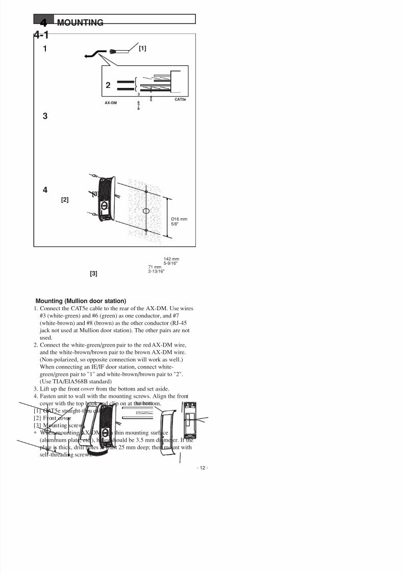
Mounting (Mullion door station)1. Connect the CAT5e cable to the rear of the AX-DM. Use wires
#3 (white-green) and #6 (green) as one conductor, and #7
(white-brown) and #8 (brown) as the other conductor (RJ-45
jack not used at Mullion door station). The other pairs are not
used.
2. Connect the white-green/green pair to the red AX-DM wire,
and the white-brown/brown pair to the brown AX-DM wire.
(Non-polarized, so opposite connection will work as well.)
When connecting an IE/IF door station, connect white-
green/green pair to "1" and white-brown/brown pair to "2".
(Use TIA/EIA568B standard)
3. Lift up the front cover from the bottom and set aside.
4. Fasten unit to wall with the mounting screws. Align the front
cover with the top hook and clip on at the bottom.
[1] CAT5e straight-thru cable
[2] Front cover
[3] Mounting screws
∗ When mounting AX-DM on a thin mounting surface
(aluminum plate, etc.), holes should be 3.5 mm diameter. If the
plate is thick, drill holes at least 25 mm deep; then mount with
self-threading screws."
[1]1
3
AX-DMCAT5e
[2][3]
[3]
4
2
142 mm5-9/16"
71 mm2-13/16"
Ø16 mm5/8"
1
245
3
678
7/29/2019 Aiphone Model AX Series - Install & Op Manual 0311- Westside Wholesale - Call 1-877-998-9378
http://slidepdf.com/reader/full/aiphone-model-ax-series-install-op-manual-0311-westside-wholesale-call 13/44
- 13 -
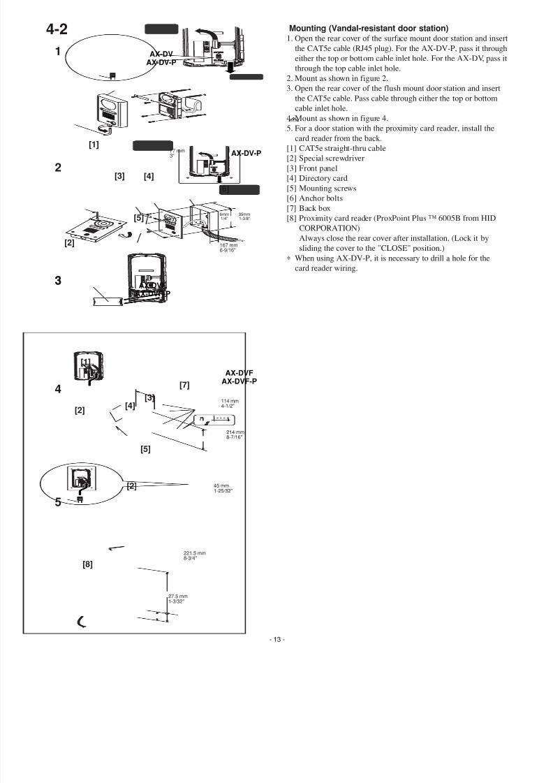
Mounting (Vandal-resistant door station)1. Open the rear cover of the surface mount door station and inse
the CAT5e cable (RJ45 plug). For the AX-DV-P, pass it throug
either the top or bottom cable inlet hole. For the AX-DV, pass
through the top cable inlet hole.
2. Mount as shown in figure 2.
3. Open the rear cover of the flush mount door station and insert
the CAT5e cable. Pass cable through either the top or bottom
cable inlet hole.
4. Mount as shown in figure 4.
5. For a door station with the proximity card reader, install thecard reader from the back.
[1] CAT5e straight-thru cable
[2] Special screwdriver
[3] Front panel
[4] Directory card
[5] Mounting screws
[6] Anchor bolts
[7] Back box
[8] Proximity card reader (ProxPoint Plus ™ 6005B from HID
CORPORATION)
Always close the rear cover after installation. (Lock it by
sliding the cover to the "CLOSE" position.)
∗ When using AX-DV-P, it is necessary to drill a hole for the
card reader wiring.
4-2
AX-DVAX-DV-P
AX-DV-P
AX-DVFAX-DVF-P
AX-DVF
AX-DVF-P
1
3
4
5
214 mm8-7/16"
45 mm1-25/32"
114 mm4-1/2"
77 mm3"
[1]
[2]
[2]
[8]
[4][3]
[7]
[5]
2
3
[2]
[3] [4]
[6]
[5]6mm1/4"
35mm1-3/8"
167 mm6-9/16"
[1]
221.5 mm8-3/4"
27.5 mm1-3/32"
7/29/2019 Aiphone Model AX Series - Install & Op Manual 0311- Westside Wholesale - Call 1-877-998-9378
http://slidepdf.com/reader/full/aiphone-model-ax-series-install-op-manual-0311-westside-wholesale-call 14/44
- 14 -
4-3
AX-DV
77 mm3"
8.5mm5/16"1.3 mm
1/16"
100 mm3-15/16"
2 4 m m
1 5 / 1 6 "
8 2 . 5
m m
3 - 1 / 4 "
8 2 . 5
m m
3 - 1 / 4 "
1 4 m m
9 / 1 6 "
1 4 m m
9 / 1 6 "
1 6 7 m m
6 - 9 / 1 6 "
1 9 5 m m
7 - 1 1 / 1 6 "
6 0 . 5
m m
2 - 3 / 8 "
1 0 6 . 5
m m
4 - 3 / 1 6 "
AX-DV-P
77 mm3"
8.5 mm5/16"
1.3 mm1/16"
100 mm3-15/16"
2 4 m m
1 5 / 1 6 "
1 4 m m
9 / 1 6 "
9 . 5
m m
3 / 8 "
2 2 1 . 5
m m
8 - 3 / 4 "
2 4 5 m m
9 - 5 / 8 "
8 7 . 5
m m
3 -
7 / 1 6 "
2 7 . 5
m m
1 - 1 / 1 6 "
1 0 6 . 5
m m
4 - 3 / 1 6 "
AX-DVF
104 mm4-1/8"
114 mm4-1/2"(BOX)
16 mm5/8"
16 mm5/8"
114 mm4-1/2"(BOX)
16 mm5/8"
16 mm5/8"
146 mm5-3/4"
4 7 . 5
m m
1 - 7 / 8 "
1 6 m m
5 / 8 "
2 6 m m
1 "
2 4 6 m m
9 - 1 1 / 1 6 "
1 9 4 m m
7 - 5 / 8 "
2 6 m m
1 "
1 6 m m
5 / 8 "
1 6 m m
5 / 8 "
1 6 m m
5 / 8 "
2 1 4 m m
8 - 7 / 1 6 "
( B O X )
1 0 m m
3 / 8 "
1 0 m m
3 / 8 "
1 0 m m
3 / 8 "
1 0 m m
3 / 8 "
AX-DVF-P
104 mm4-1/8"
5 mm3/16"
5 mm3/16"
146 mm5-3/4"
4 7 . 5
m m
1 - 7 / 8 "
2 6 m m
1 "
2 6 m m
1 "
2 9 5 m m
1 1 - 5 / 8 "
2 4 3 m m
9 - 9 / 1 6 "
2 6 3 m m
1 0 - 3 / 8 "
( B O X )
[2]fl16 mm5/8"
[1]
[2]
[1]
[2]
[1]
[1]

7/29/2019 Aiphone Model AX Series - Install & Op Manual 0311- Westside Wholesale - Call 1-877-998-9378
http://slidepdf.com/reader/full/aiphone-model-ax-series-install-op-manual-0311-westside-wholesale-call 15/44- 15 -
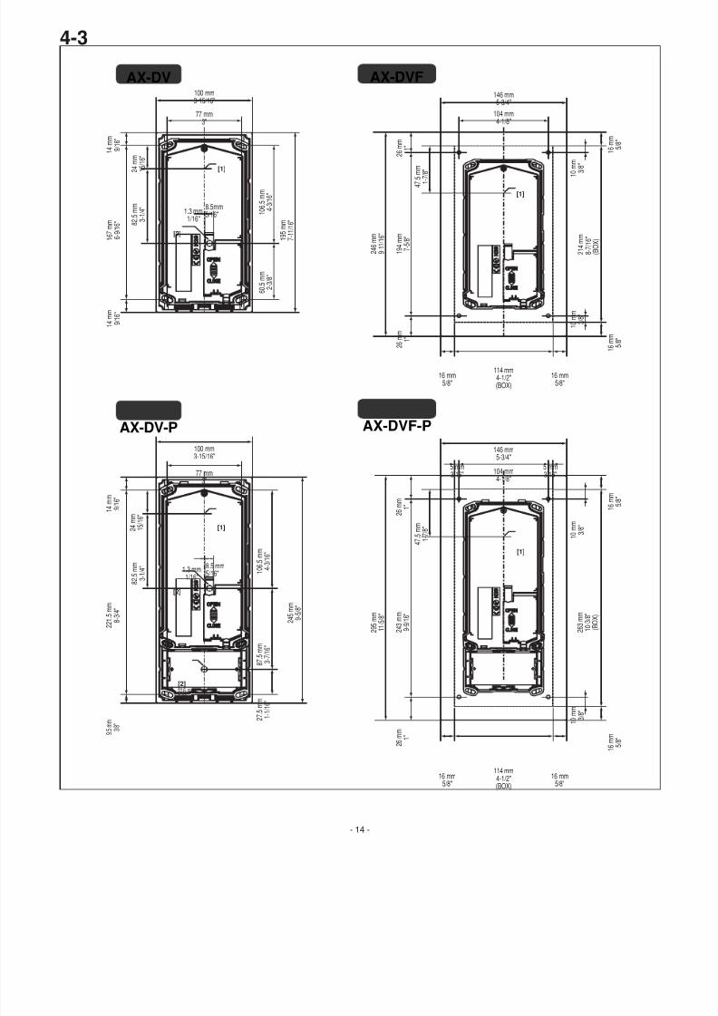
4-3Door station installation dimensions
[1] Center position of camera
[2] Wiring holes Ø 16 mm 5/8"
7/29/2019 Aiphone Model AX Series - Install & Op Manual 0311- Westside Wholesale - Call 1-877-998-9378
http://slidepdf.com/reader/full/aiphone-model-ax-series-install-op-manual-0311-westside-wholesale-call 16/44
- 16 -
1
AX-8MAX-8MV
[1]
2
3
a b
AX-8MAX-8MVAX-16SW
[2]
[5]
[3] [3]
[4]
[4]
83.5 mm3-5/16"
65 mm2-9/16"
149 mm5-7/8"
46 mm1-13/16"
[2]
4-4
[6]
[7]
7/29/2019 Aiphone Model AX Series - Install & Op Manual 0311- Westside Wholesale - Call 1-877-998-9378
http://slidepdf.com/reader/full/aiphone-model-ax-series-install-op-manual-0311-westside-wholesale-call 17/44
- 17 -
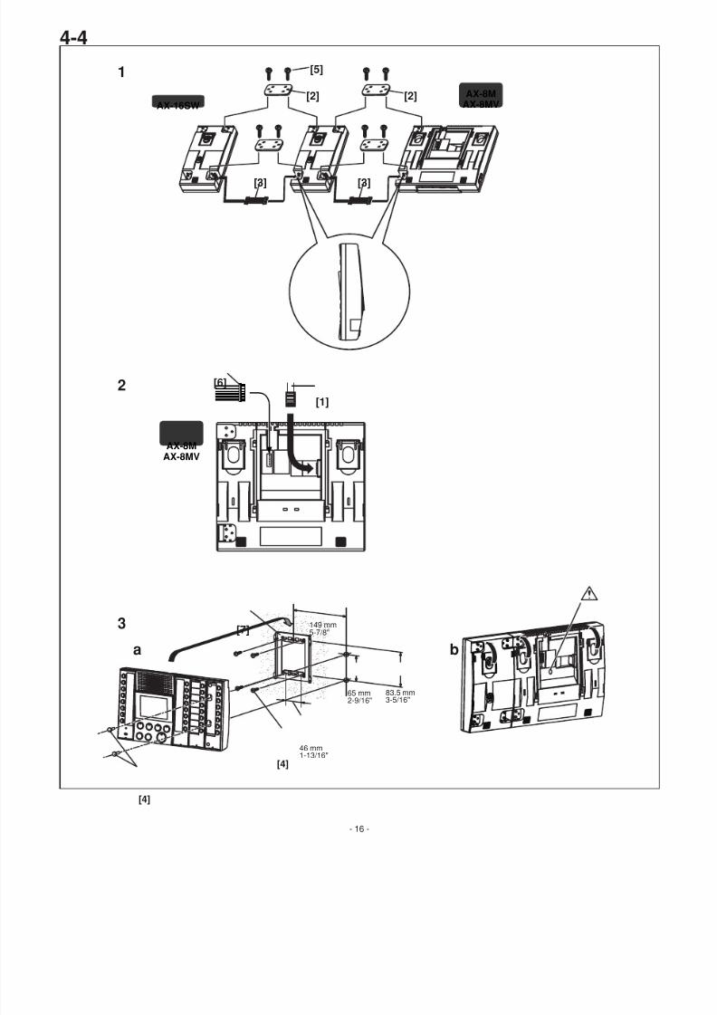
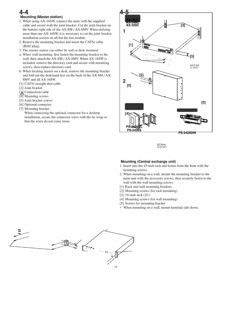
4-5Mounting (Master station)
1. When using AX-16SW, connect the units with the supplied
cable and secure with the joint bracket. Cut the joint bracket on
the bottom right side of the AX-8M / AX-8MV. When utilizing
more than one AX-16SW, it is necessary to cut the joint bracket
installation section on all but the last module.
2. Remove the mounting bracket and insert the CAT5e cable
(RJ45 plug).
3. The master station can either be wall or desk mounted.
a. When wall mounting, first fasten the mounting bracket to the
wall, then attach the AX-8M / AX-8MV. When AX-16SW is
included, remove the directory card and secure with mounting
screws, then replace directory card.
b. When locating master on a desk, remove the mounting bracket
and fold out the deskstand feet on the back of the AX-8M / AX-
8MV and all AX-16SW.
[1] CAT5e straight-thru cable
[2] Joint bracket
[3] Connection cable
[4] Mounting screws
[5] Joint bracket screws
[6] Optional connector [7] Mounting bracket
When connecting the optional connector for a desktop
installation, secure the connector wires with the tie wrap so
that the wires do not come loose.
4-4
Mounting (Central exchange unit)1. Insert into the 19-inch rack and fasten from the front with the
mounting screws.
2. When mounting on a wall, mount the mounting bracket to the
main unit with the accessory screws, then securely fasten to th
wall with the wall mounting screws.
[1] Rack and wall mounting brackets
[2] Mounting screws (for rack mounting)
[3] 19-inch rack (2U)
[4] Mounting screws (for wall mounting)
[5] Screws for mounting bracket
∗ When mounting on a wall, mount terminal side down.
AX-084CAX-248CAX-320C
83.5mm(3-5/16")
PS-2420DIN
PS-2420ULPS-2420S
[1]
[5]
[5]
[3]
[2]
44.5 mm(1-3/4")
D1D2
D3D4 D7D6
D8
D5
M1M2
M3M4
DOOR STATION
MASER STATION
L1L2 L3 L
4L7
L6L8
L5
DOOR RELEASERELAY
POWER
V1V2
VIDEO OUTPUT
COTEL ADAPTOR
LOG / SETTINGRS-232C
+- +
-D-PS
AX-084C
X1X2
AX-320C
VCH1 VCH2
V-PS
POWER
DC24V
ø 0.65~ø 1.2
11mm This is not a computer peripheral.
Do NOT connect toLAN network.
STRIPLENGTH
[4]
[5]
1
2
[5]
7/29/2019 Aiphone Model AX Series - Install & Op Manual 0311- Westside Wholesale - Call 1-877-998-9378
http://slidepdf.com/reader/full/aiphone-model-ax-series-install-op-manual-0311-westside-wholesale-call 18/44
5 WIRING
5-12
NP
OP
IER-2
OP
AX-084C
AX-248C
AX-320C
AX-8MV
AX-8M
1
E
[1]
[14] [2]
[3]
PS-2420DIN
+ -
100V-240V~
50/60Hz
230V ACN
L
24V DC2A
24V DC
2A
IN 230V~ 50/60Hz NL
2A - +
-
+
PS-2420UL
PS-2420S
PC
PS
PS
PS
Max. 3
[4]
AX-320C
[4]
AX-320C
[4]
[5]
[6]
[9]
[7]
[10]
[11]
[12]
[13]
OP
PT
EL-12S
AX-DM
IF-DA
IE-JA
CAT5e
AX-DV
AX-DV-P
AX-DVF
AX-DVF-P
1
2
3
4
5
RxD
TxD
GND
6
7
8
9
1
2
3
4
5
RxD
TxD
GND
6
7
8
9
RS-232C
VCH1(VCH2)
AX-084C
AX-248C PC
1 2 3 4 5 6 7 8
GND(GND)VCH1(VCH2)
DC 24 V, 30 mA max.
[8]
CAT5eCAT5e
RS-232C
CAT5eCAT5eCAT5e
CAT5eCAT5e
CAT5eCAT5e
D
AX-16SW Max. 7
M
RJ45
RJ45
+-
+-
+ - + -
D-PS V-PS
DC24V
PS+-
2
1
1
2CAT5e
- 18 -
7/29/2019 Aiphone Model AX Series - Install & Op Manual 0311- Westside Wholesale - Call 1-877-998-9378
http://slidepdf.com/reader/full/aiphone-model-ax-series-install-op-manual-0311-westside-wholesale-call 19/44
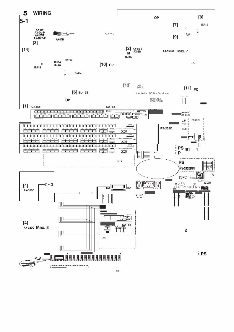
5-1Wiring
Securely insert wires into each terminal as shown.
[1] AX-248C or AX-084C central exchange unit
[2] AX-8MV video master station or AX-8M master station
AX-16SW 16 call add-on selector
[3] Video or audio-only door station
[4] AX-320C add-on exchange unit
ID setting switch
1st unit: 22nd unit: 3
3rd unit: 4
[5] Power supply (DC 24 V,2 A)
• Video system: 2 pcs
1. Connect 2 pcs of power supply separately for video and
audio.
• Audio system: 1 pce
2. Connect power supply as in the figure.
[6] Optional door release device (EL-12S or other locally
available)
A separate AC transformer is required.
The terminals that correspond to door stations D1 and D2 are
L1 and L2 respectively.Door release contact: AC/DC 24 V, 0.5 A (dry closure contact
L, L).
Wiring distance: 300 m, 980' (Ø1.2 mm, 16 AWG)
[7] Video output (option): Brown (video +), red (video -)
Wiring distance: 15 m, 50' (coaxial cable: 5C-2V, RG-59/U
(20AWG))
Cut off unused wires and insulate the ends to prevent
shorting.
[8] External signaling speaker IER-2 (optional): Yellow, Orange
Wiring distance: 150 m, 490' (Ø1.0 mm, 18 AWG)
Cut off unused wires and insulate the ends to prevent
shorting.
[9] Footswitch (option, locally available): Green, blue (dryclosure contact input)
Wiring distance: 15 m, 50' (Ø1.0 mm, 18 AWG)
Cut off unused wires and insulate the ends to prevent
shorting.
[10] Computer-style Headset (option)
[11] PC (log/setting): RS-232C straight-thru cable (locally
available)
Wiring distance: 15 m, 50'
[12] CO line adaptor: Hot-Line Touch Tone Dialer K-1900-5
(from Viking Electronics, Inc.)
(For North America only; contact AIPHONE CORPORATION)
Wiring distance: 15 m, 50'
System might be unable to connect with PBX.
[13] Video output and video switching signals (open collector
output for video output)
Wiring distance: 15 m, 50' (coaxial cable: 5C-2V, RG-59/U
(20GA))
When the camera is switched, the image may be distorted.
This is normal.
[14] Access control system
- 19 -
7/29/2019 Aiphone Model AX Series - Install & Op Manual 0311- Westside Wholesale - Call 1-877-998-9378
http://slidepdf.com/reader/full/aiphone-model-ax-series-install-op-manual-0311-westside-wholesale-call 20/44
- 20 -
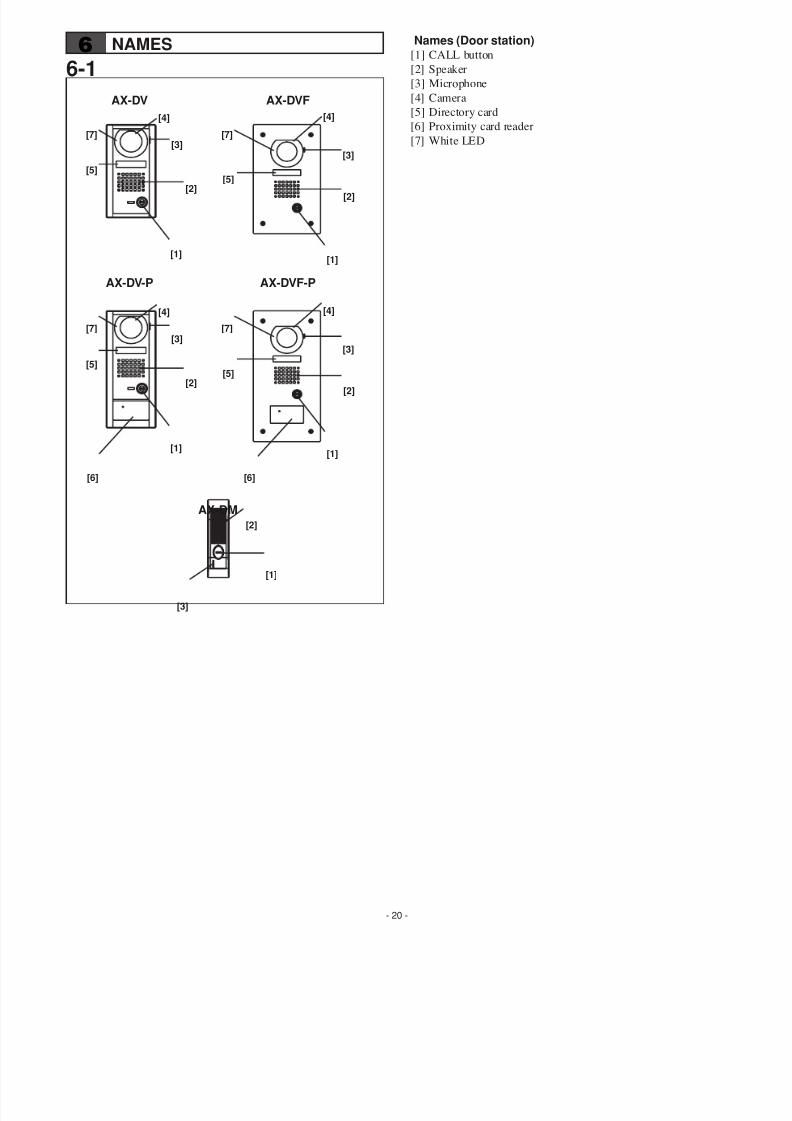
6-16 NAMES Names (Door station)
[1] CALL button
[2] Speaker
[3] Microphone
[4] Camera
[5] Directory card
[6] Proximity card reader
[7] White LED
AX-DM
AX-DV AX-DVF
AX-DV-P AX-DVF-P
[1]
[1][1]
[4]
[2]
[2]
[6] [6]
[3]
[3]
[5]
[7] [7]
[7] [7]
[1]
[4]
[2]
[3]
[5]
[4]
[2]
[3]
[5]
[1]
[4]
[2]
[3]
[5]
7/29/2019 Aiphone Model AX Series - Install & Op Manual 0311- Westside Wholesale - Call 1-877-998-9378
http://slidepdf.com/reader/full/aiphone-model-ax-series-install-op-manual-0311-westside-wholesale-call 21/44
- 21 -
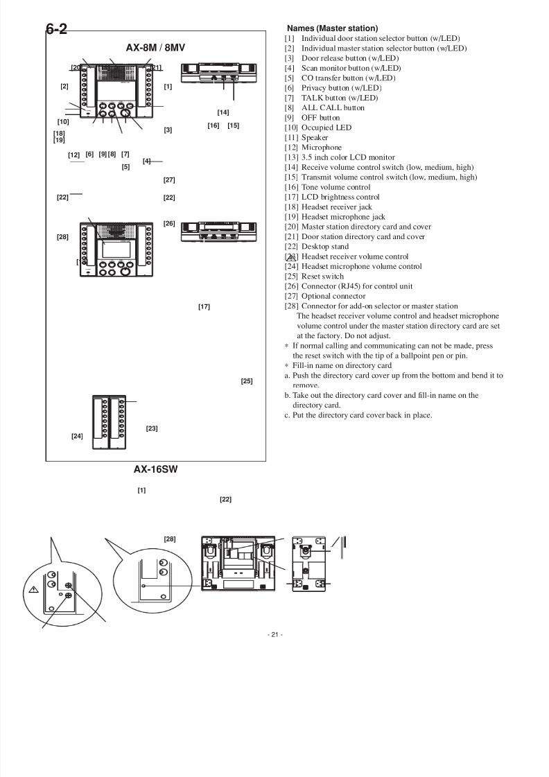
6-2 Names (Master station)[1] Individual door station selector button (w/LED)
[2] Individual master station selector button (w/LED)
[3] Door release button (w/LED)
[4] Scan monitor button (w/LED)
[5] CO transfer button (w/LED)
[6] Privacy button (w/LED)
[7] TALK button (w/LED)
[8] ALL CALL button
[9] OFF button
[10] Occupied LED[11] Speaker
[12] Microphone
[13] 3.5 inch color LCD monitor
[14] Receive volume control switch (low, medium, high)
[15] Transmit volume control switch (low, medium, high)
[16] Tone volume control
[17] LCD brightness control
[18] Headset receiver jack
[19] Headset microphone jack
[20] Master station directory card and cover
[21] Door station directory card and cover
[22] Desktop stand
[23] Headset receiver volume control
[24] Headset microphone volume control
[25] Reset switch
[26] Connector (RJ45) for control unit
[27] Optional connector
[28] Connector for add-on selector or master station
The headset receiver volume control and headset microphon
volume control under the master station directory card are se
at the factory. Do not adjust.
∗ If normal calling and communicating can not be made, press
the reset switch with the tip of a ballpoint pen or pin.
∗ Fill-in name on directory card
a. Push the directory card cover up from the bottom and bend it remove.
b. Take out the directory card cover and fill-in name on the
directory card.
c. Put the directory card cover back in place.
AX-8M / 8MV
AX-16SW
[13]
[22]
[27]
[26]
[4]
[11]
[2]
[10]
[5]
[6][12]
[3]
[9] [8] [7]
[21][20]
[1]
[1]
[18][19]
[22]
[28]
[14]
[15]
[17]
[16]
[23][24]
[25]
[22]
[28][28]
7/29/2019 Aiphone Model AX Series - Install & Op Manual 0311- Westside Wholesale - Call 1-877-998-9378
http://slidepdf.com/reader/full/aiphone-model-ax-series-install-op-manual-0311-westside-wholesale-call 22/44
- 22 -
AX-320C
AX-248C
AX-084C
6-3
[10]
[8]
[2] [5]
[6][9] [3][1]
[4]
[12]
[7]
[8]
[10][2] [3] [4] [5]
[7] [6][9][1]
[12]
[4] [10][11][2]
[1]
[12]
[9]
7/29/2019 Aiphone Model AX Series - Install & Op Manual 0311- Westside Wholesale - Call 1-877-998-9378
http://slidepdf.com/reader/full/aiphone-model-ax-series-install-op-manual-0311-westside-wholesale-call 23/44
- 23 -
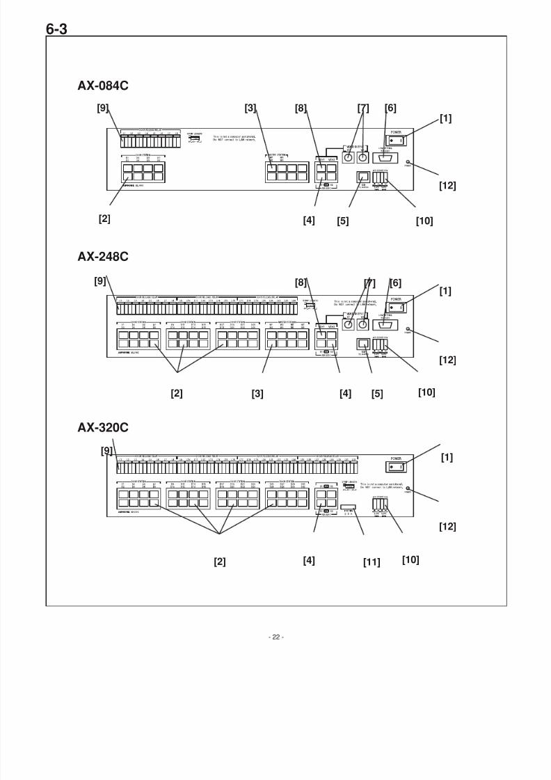
Names (Central exchange unit)[1] POWER switch
[2] Door station port
[3] Master station port
[4] Add-on exchange unit port
[5] CO line port
[6] Setting/log port
[7] Video output port
[8] Video output trigger port
[9] Door release relay port (L1 corresponds to door station D1,
L2 to door station D2, etc.)
[10] Power supply port
[11] Add-on unit ID setting switch
1st unit: 2
2nd unit: 3
3rd unit: 4
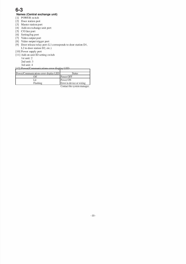
[12] Power/Communications error display LED
6-3
Power/Communications error display LED Status
Power OFF
Power ONError in device or wiring
Contact the system manager.
Off
LitFlashing
7/29/2019 Aiphone Model AX Series - Install & Op Manual 0311- Westside Wholesale - Call 1-877-998-9378
http://slidepdf.com/reader/full/aiphone-model-ax-series-install-op-manual-0311-westside-wholesale-call 24/44
- 24 -
7 SETTING UP
7-1
AX-248C
RS-232C
1
2
3
[1] [2] [3] [4] [5] [6] [7] [8] [9] [10] [11]
3
7/29/2019 Aiphone Model AX Series - Install & Op Manual 0311- Westside Wholesale - Call 1-877-998-9378
http://slidepdf.com/reader/full/aiphone-model-ax-series-install-op-manual-0311-westside-wholesale-call 25/44
- 25 -
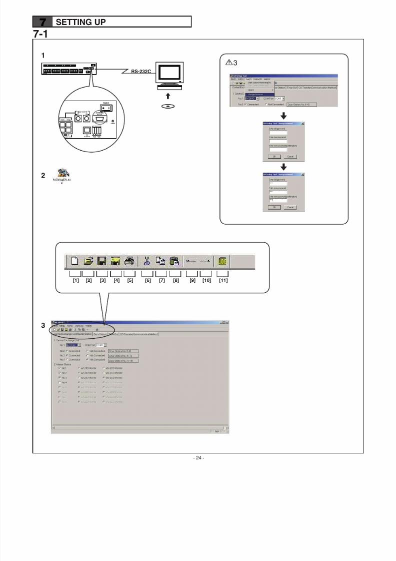
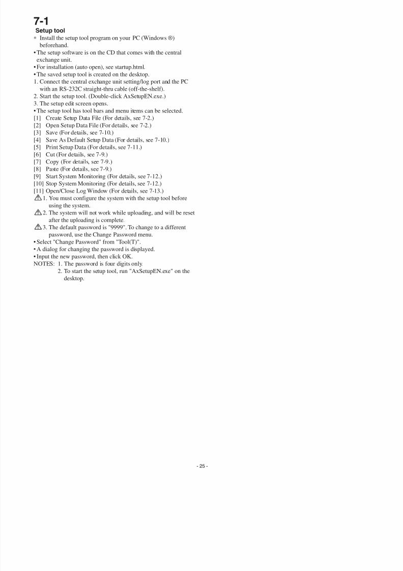
7-1Setup tool
∗ Install the setup tool program on your PC (Windows ®)
beforehand.
• The setup software is on the CD that comes with the central
exchange unit.
• For installation (auto open), see startup.html.
• The saved setup tool is created on the desktop.
1. Connect the central exchange unit setting/log port and the PC
with an RS-232C straight-thru cable (off-the-shelf).
2. Start the setup tool. (Double-click AxSetupEN.exe.)
3. The setup edit screen opens.
• The setup tool has tool bars and menu items can be selected.
[1] Create Setup Data File (For details, see 7-2.)
[2] Open Setup Data File (For details, see 7-2.)
[3] Save (For details, see 7-10.)
[4] Save As Default Setup Data (For details, see 7-10.)
[5] Print Setup Data (For details, see 7-11.)
[6] Cut (For details, see 7-9.)
[7] Copy (For details, see 7-9.)
[8] Paste (For details, see 7-9.)
[9] Start System Monitoring (For details, see 7-12.)
[10] Stop System Monitoring (For details, see 7-12.)[11] Open/Close Log Window (For details, see 7-13.)
1. You must configure the system with the setup tool before
using the system.
2. The system will not work while uploading, and will be reset
after the uploading is complete.
3. The default password is "9999". To change to a different
password, use the Change Password menu.
• Select "Change Password" from "Tool(T)".
• A dialog for changing the password is displayed.
• Input the new password, then click OK.
NOTES: 1. The password is four digits only.
2. To start the setup tool, run "AxSetupEN.exe" on the
desktop.
7/29/2019 Aiphone Model AX Series - Install & Op Manual 0311- Westside Wholesale - Call 1-877-998-9378
http://slidepdf.com/reader/full/aiphone-model-ax-series-install-op-manual-0311-westside-wholesale-call 26/44
- 26 -
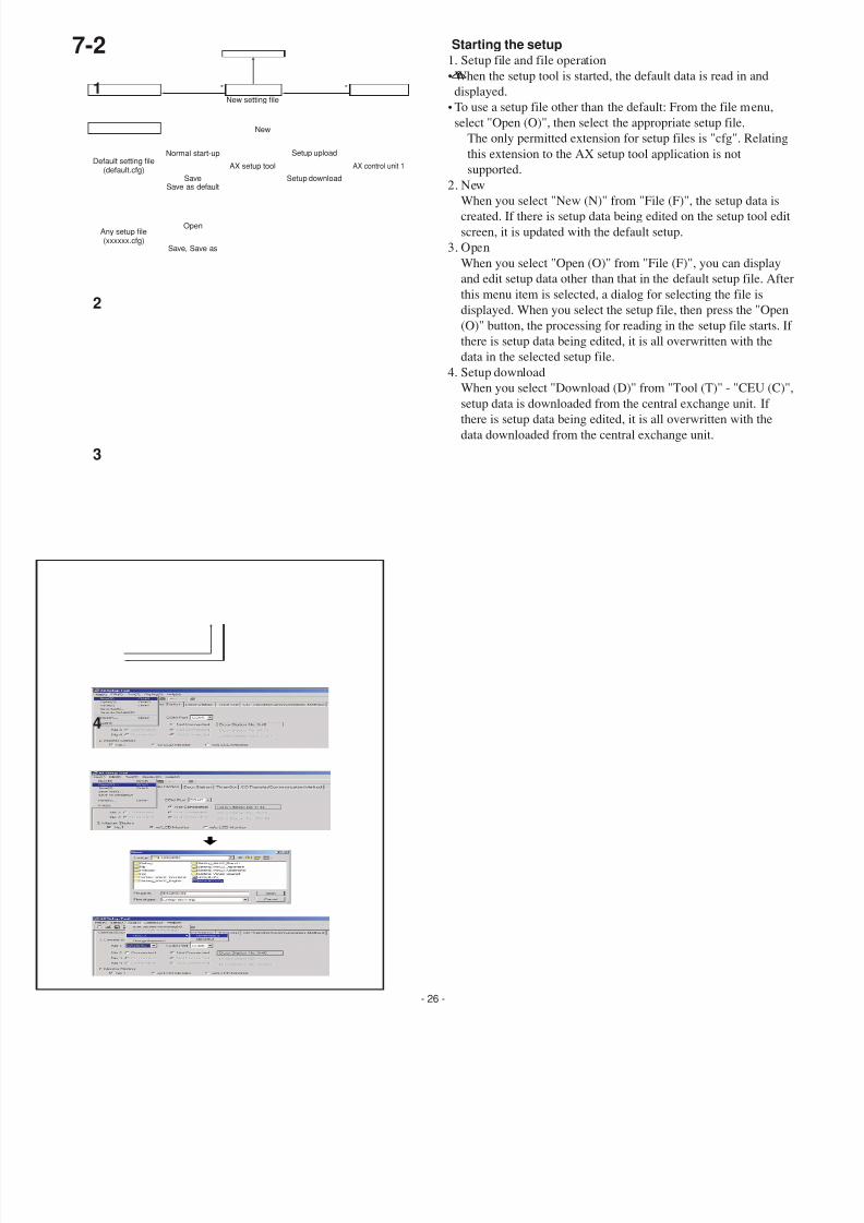
Starting the setup1. Setup file and file operation
• When the setup tool is started, the default data is read in and
displayed.
• To use a setup file other than the default: From the file menu,
select "Open (O)", then select the appropriate setup file.
The only permitted extension for setup files is "cfg". Relatin
this extension to the AX setup tool application is not
supported.
2. New
When you select "New (N)" from "File (F)", the setup data iscreated. If there is setup data being edited on the setup tool ed
screen, it is updated with the default setup.
3. Open
When you select "Open (O)" from "File (F)", you can display
and edit setup data other than that in the default setup file. Aft
this menu item is selected, a dialog for selecting the file is
displayed. When you select the setup file, then press the "Ope
(O)" button, the processing for reading in the setup file starts.
there is setup data being edited, it is all overwritten with the
data in the selected setup file.
4. Setup download
When you select "Download (D)" from "Tool (T)" - "CEU (C
setup data is downloaded from the central exchange unit. If
there is setup data being edited, it is all overwritten with the
data downloaded from the central exchange unit.
7-2
New
Normal start-up
Open
Save, Save as
Setup upload
Setup downloadSaveSave as default
New setting file
Default setting file(default.cfg)
AX setup tool AX control unit 1
Any setup file(xxxxxx.cfg)
2
3
4
1
7/29/2019 Aiphone Model AX Series - Install & Op Manual 0311- Westside Wholesale - Call 1-877-998-9378
http://slidepdf.com/reader/full/aiphone-model-ax-series-install-op-manual-0311-westside-wholesale-call 27/44
- 27 -
7-3 7-4
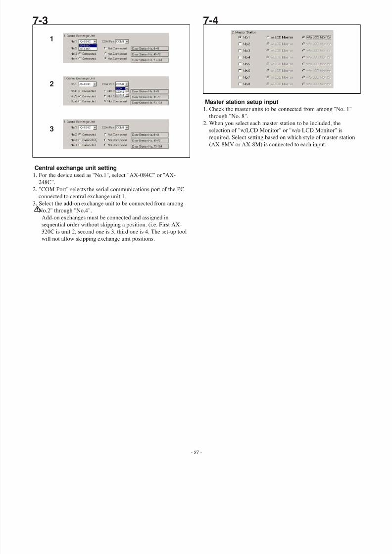
Central exchange unit setting1. For the device used as "No.1", select "AX-084C" or "AX-
248C".
2. "COM Port" selects the serial communications port of the PC
connected to central exchange unit 1.
3. Select the add-on exchange unit to be connected from among
"No.2" through "No.4".
Add-on exchanges must be connected and assigned in
sequential order without skipping a position. (i.e. First AX-
320C is unit 2, second one is 3, third one is 4. The set-up tool
will not allow skipping exchange unit positions.
Master station setup input1. Check the master units to be connected from among "No. 1"
through "No. 8".
2. When you select each master station to be included, the
selection of "w/LCD Monitor" or "w/o LCD Monitor" is
required. Select setting based on which style of master station
(AX-8MV or AX-8M) is connected to each input.
1
2
3
7/29/2019 Aiphone Model AX Series - Install & Op Manual 0311- Westside Wholesale - Call 1-877-998-9378
http://slidepdf.com/reader/full/aiphone-model-ax-series-install-op-manual-0311-westside-wholesale-call 28/44
- 28 -
[1] [2] [3] [4] [5] [6] [7] [8]
[9]
[3] [4]
1
2
3
7-5
7/29/2019 Aiphone Model AX Series - Install & Op Manual 0311- Westside Wholesale - Call 1-877-998-9378
http://slidepdf.com/reader/full/aiphone-model-ax-series-install-op-manual-0311-westside-wholesale-call 29/44
- 29 -
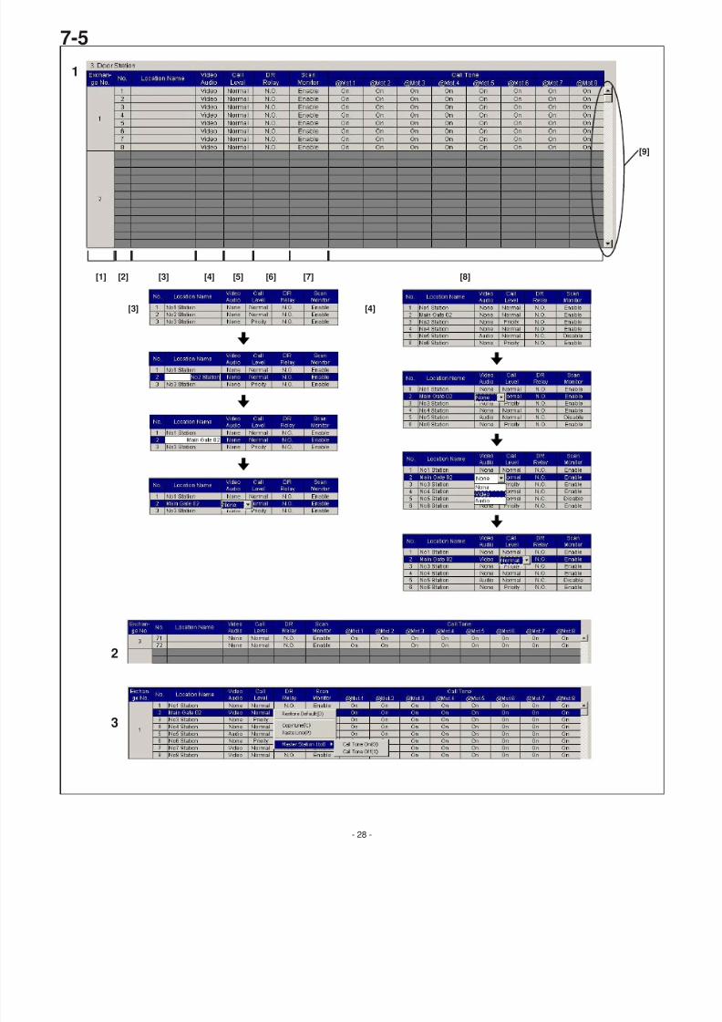
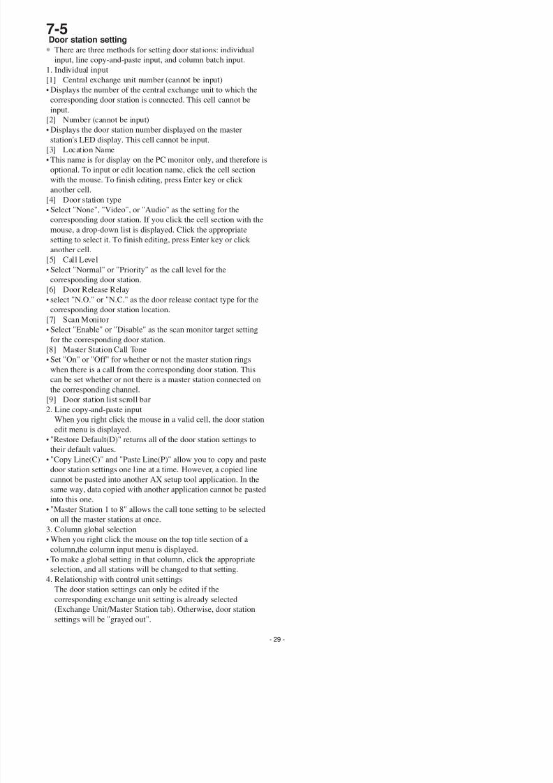
Door station setting∗ There are three methods for setting door stations: individual
input, line copy-and-paste input, and column batch input.
1. Individual input
[1] Central exchange unit number (cannot be input)
• Displays the number of the central exchange unit to which the
corresponding door station is connected. This cell cannot be
input.
[2] Number (cannot be input)
• Displays the door station number displayed on the master
station's LED display. This cell cannot be input.
[3] Location Name
• This name is for display on the PC monitor only, and therefore is
optional. To input or edit location name, click the cell section
with the mouse. To finish editing, press Enter key or click
another cell.
[4] Door station type
• Select "None", "Video", or "Audio" as the setting for the
corresponding door station. If you click the cell section with the
mouse, a drop-down list is displayed. Click the appropriate
setting to select it. To finish editing, press Enter key or click
another cell.
[5] Call Level
• Select "Normal" or "Priority" as the call level for the
corresponding door station.
[6] Door Release Relay
• select "N.O." or "N.C." as the door release contact type for the
corresponding door station location.
[7] Scan Monitor
• Select "Enable" or "Disable" as the scan monitor target setting
for the corresponding door station.
[8] Master Station Call Tone
• Set "On" or "Off" for whether or not the master station rings
when there is a call from the corresponding door station. This
can be set whether or not there is a master station connected onthe corresponding channel.
[9] Door station list scroll bar
2. Line copy-and-paste input
When you right click the mouse in a valid cell, the door station
edit menu is displayed.
• "Restore Default(D)" returns all of the door station settings to
their default values.
• "Copy Line(C)" and "Paste Line(P)" allow you to copy and paste
door station settings one line at a time. However, a copied line
cannot be pasted into another AX setup tool application. In the
same way, data copied with another application cannot be pasted
into this one.
• "Master Station 1 to 8" allows the call tone setting to be selectedon all the master stations at once.
3. Column global selection
• When you right click the mouse on the top title section of a
column,the column input menu is displayed.
• To make a global setting in that column, click the appropriate
selection, and all stations will be changed to that setting.
4. Relationship with control unit settings
The door station settings can only be edited if the
corresponding exchange unit setting is already selected
(Exchange Unit/Master Station tab). Otherwise, door station
settings will be "grayed out".
7-5
7/29/2019 Aiphone Model AX Series - Install & Op Manual 0311- Westside Wholesale - Call 1-877-998-9378
http://slidepdf.com/reader/full/aiphone-model-ax-series-install-op-manual-0311-westside-wholesale-call 30/44
- 30 -
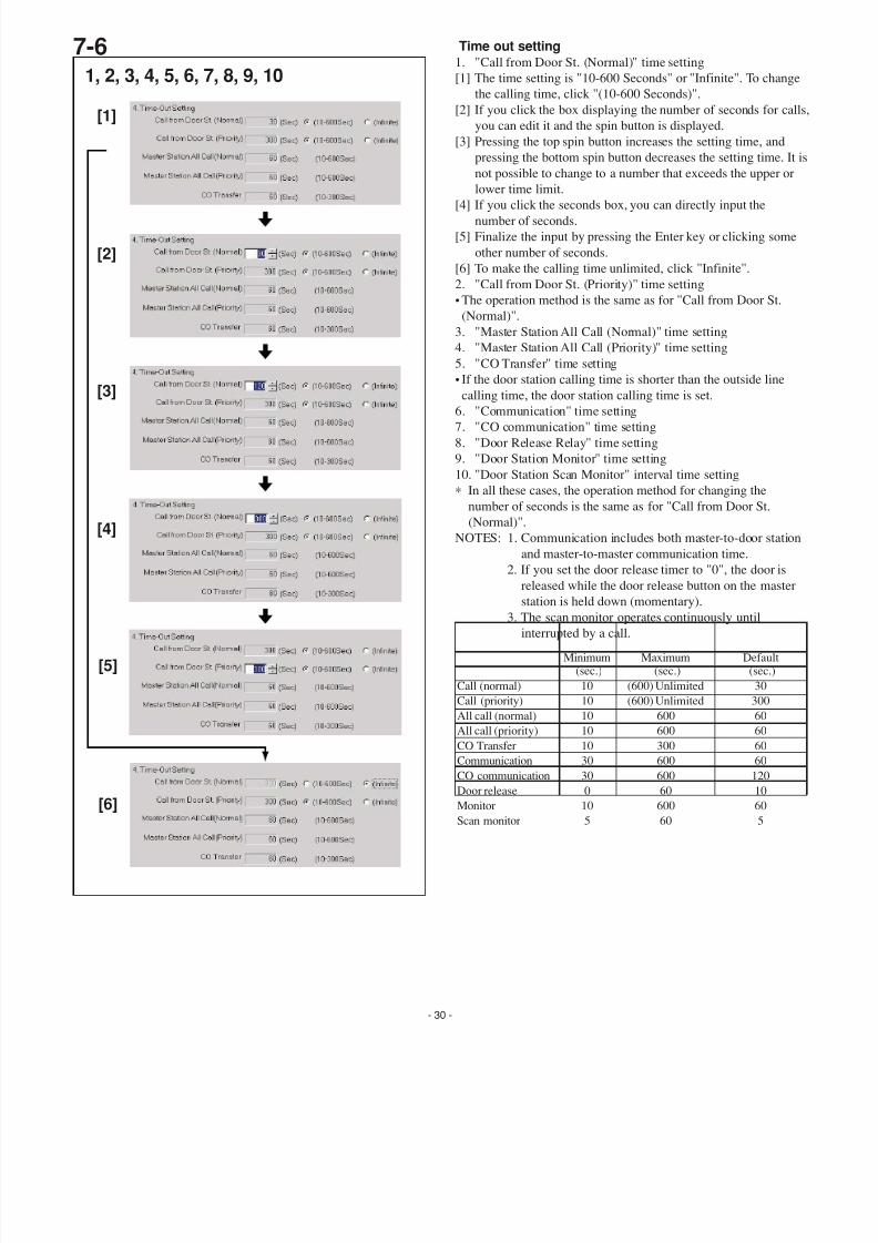
Time out setting1. "Call from Door St. (Normal)" time setting
[1] The time setting is "10-600 Seconds" or "Infinite". To chang
the calling time, click "(10-600 Seconds)".
[2] If you click the box displaying the number of seconds for ca
you can edit it and the spin button is displayed.
[3] Pressing the top spin button increases the setting time, and
pressing the bottom spin button decreases the setting time. It
not possible to change to a number that exceeds the upper or
lower time limit.
[4] If you click the seconds box, you can directly input thenumber of seconds.
[5] Finalize the input by pressing the Enter key or clicking some
other number of seconds.
[6] To make the calling time unlimited, click "Infinite".
2. "Call from Door St. (Priority)" time setting
• The operation method is the same as for "Call from Door St.
(Normal)".
3. "Master Station All Call (Normal)" time setting
4. "Master Station All Call (Priority)" time setting
5. "CO Transfer" time setting
• If the door station calling time is shorter than the outside line
calling time, the door station calling time is set.
6. "Communication" time setting
7. "CO communication" time setting
8. "Door Release Relay" time setting
9. "Door Station Monitor" time setting
10. "Door Station Scan Monitor" interval time setting
∗ In all these cases, the operation method for changing the
number of seconds is the same as for "Call from Door St.
(Normal)".
NOTES: 1. Communication includes both master-to-door statio
and master-to-master communication time.
2. If you set the door release timer to "0", the door is
released while the door release button on the master
station is held down (momentary).3. The scan monitor operates continuously until
interrupted by a call.
Maximum(sec.)
Default(sec.)
Call (normal) 10
10
10
30
30
10
10
105
0
(600) Unlimited
(600) Unlimited
300
600
600
600
600
60060
60
30
300
60
60
120
60
60
605
10
Call (priority)
CO Transfer
Communication
Monitor Scan monitor
Door release
CO communication
All call (normal)
All call (priority)
Minimum(sec.)
7-6
[1]
1, 2, 3, 4, 5, 6, 7, 8, 9, 10
[2]
[3]
[4]
[5]
[6]
7/29/2019 Aiphone Model AX Series - Install & Op Manual 0311- Westside Wholesale - Call 1-877-998-9378
http://slidepdf.com/reader/full/aiphone-model-ax-series-install-op-manual-0311-westside-wholesale-call 31/44
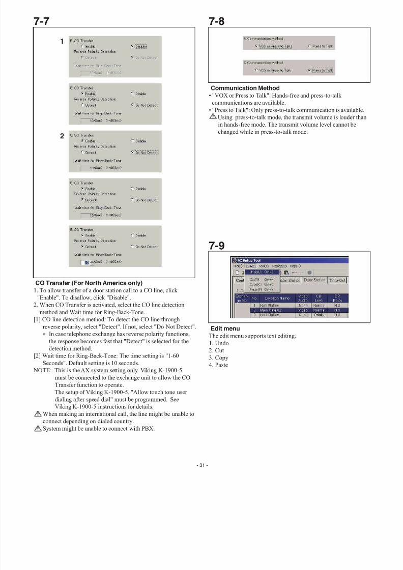
Edit menuThe edit menu supports text editing.
1. Undo
2. Cut
3. Copy
4. Paste
7-7 7-8
CO Transfer (For North America only)
1. To allow transfer of a door station call to a CO line, click
"Enable". To disallow, click "Disable".
2. When CO Transfer is activated, select the CO line detection
method and Wait time for Ring-Back-Tone.
[1] CO line detection method: To detect the CO line through
reverse polarity, select "Detect". If not, select "Do Not Detect".
∗ In case telephone exchange has reverse polarity functions,
the response becomes fast that "Detect" is selected for the
detection method.
[2] Wait time for Ring-Back-Tone: The time setting is "1-60
Seconds". Default setting is 10 seconds.
NOTE: This is the AX system setting only. Viking K-1900-5must be connected to the exchange unit to allow the CO
Transfer function to operate.
The setup of Viking K-1900-5, "Allow touch tone user
dialing after speed dial" must be programmed. See
Viking K-1900-5 instructions for details.
When making an international call, the line might be unable to
connect depending on dialed country.
System might be unable to connect with PBX.
Communication Method
• "VOX or Press to Talk": Hands-free and press-to-talk
communications are available.
• "Press to Talk": Only press-to-talk communication is available.
Using press-to-talk mode, the transmit volume is louder than
in hands-free mode. The transmit volume level cannot be
changed while in press-to-talk mode.
7-9
1
2
- 31 -
7/29/2019 Aiphone Model AX Series - Install & Op Manual 0311- Westside Wholesale - Call 1-877-998-9378
http://slidepdf.com/reader/full/aiphone-model-ax-series-install-op-manual-0311-westside-wholesale-call 32/44
- 32 -
3
4
5
6
7-10
1
New
Normal start-up
Open
Save, Save as
Setup upload
Setup downloadSaveSave as default
New setting file
Default setting file(default.cfg)
AX setup tool AX control unit 1
Any setup file(xxxxxx.cfg)
2
7/29/2019 Aiphone Model AX Series - Install & Op Manual 0311- Westside Wholesale - Call 1-877-998-9378
http://slidepdf.com/reader/full/aiphone-model-ax-series-install-op-manual-0311-westside-wholesale-call 33/44
- 33 -
7-11
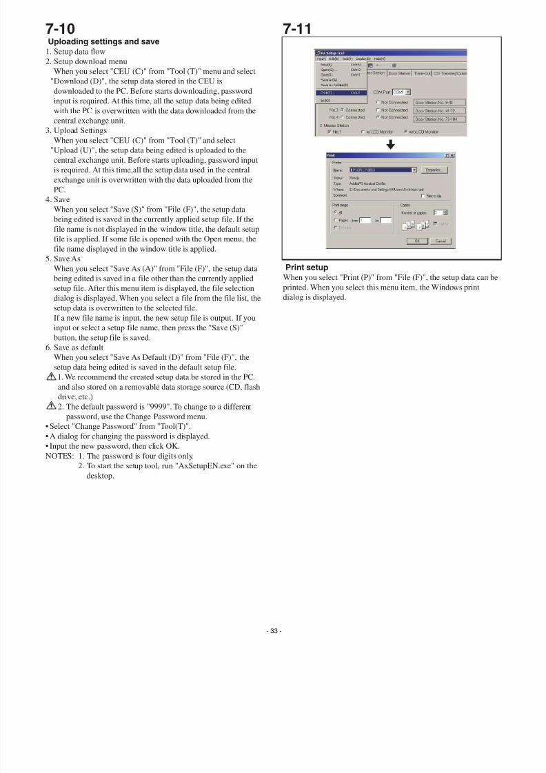
Print setup
When you select "Print (P)" from "File (F)", the setup data can b
printed. When you select this menu item, the Windows print
dialog is displayed.
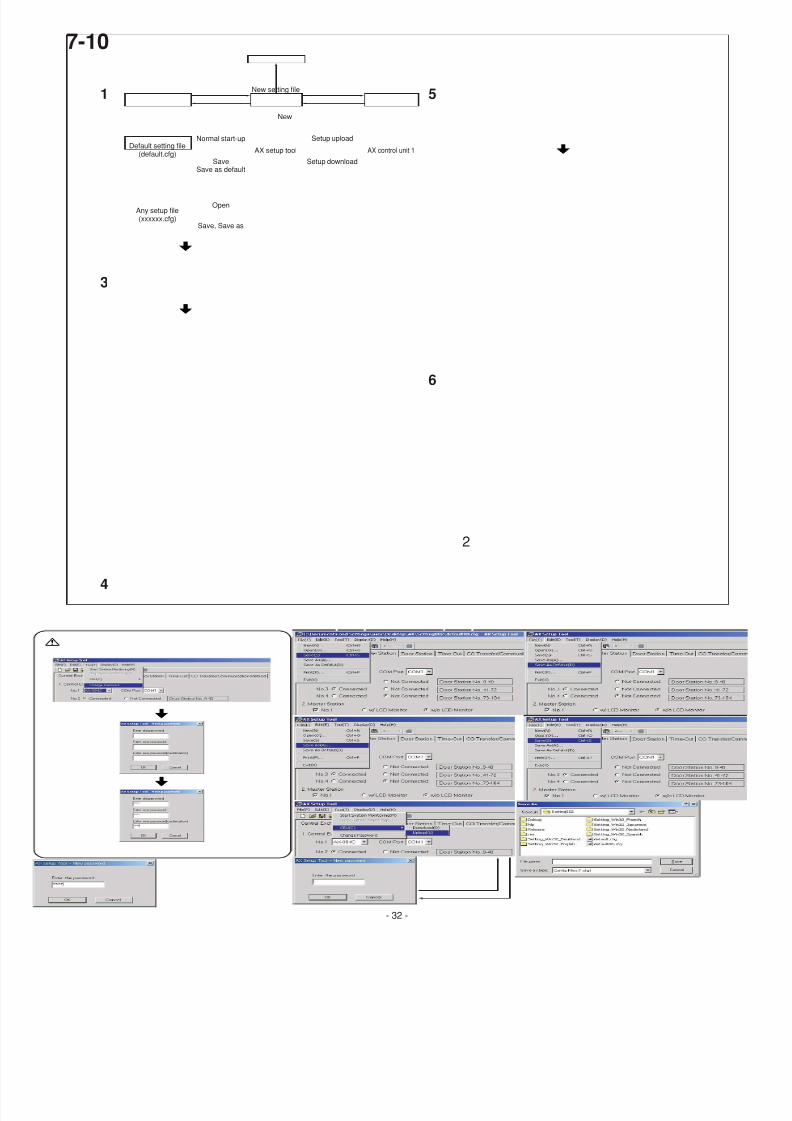
7-10Uploading settings and save
1. Setup data flow
2. Setup download menu
When you select "CEU (C)" from "Tool (T)" menu and select
"Download (D)", the setup data stored in the CEU is
downloaded to the PC. Before starts downloading, password
input is required. At this time, all the setup data being edited
with the PC is overwritten with the data downloaded from the
central exchange unit.
3. Upload Settings
When you select "CEU (C)" from "Tool (T)" and select
"Upload (U)", the setup data being edited is uploaded to the
central exchange unit. Before starts uploading, password input
is required. At this time,all the setup data used in the central
exchange unit is overwritten with the data uploaded from the
PC.
4. Save
When you select "Save (S)" from "File (F)", the setup data
being edited is saved in the currently applied setup file. If the
file name is not displayed in the window title, the default setup
file is applied. If some file is opened with the Open menu, the
file name displayed in the window title is applied.5. Save As
When you select "Save As (A)" from "File (F)", the setup data
being edited is saved in a file other than the currently applied
setup file. After this menu item is displayed, the file selection
dialog is displayed. When you select a file from the file list, the
setup data is overwritten to the selected file.
If a new file name is input, the new setup file is output. If you
input or select a setup file name, then press the "Save (S)"
button, the setup file is saved.
6. Save as default
When you select "Save As Default (D)" from "File (F)", the
setup data being edited is saved in the default setup file.
1. We recommend the created setup data be stored in the PC,and also stored on a removable data storage source (CD, flash
drive, etc.)
2. The default password is "9999". To change to a different
password, use the Change Password menu.
• Select "Change Password" from "Tool(T)".
• A dialog for changing the password is displayed.
• Input the new password, then click OK.
NOTES: 1. The password is four digits only.
2. To start the setup tool, run "AxSetupEN.exe" on the
desktop.
7/29/2019 Aiphone Model AX Series - Install & Op Manual 0311- Westside Wholesale - Call 1-877-998-9378
http://slidepdf.com/reader/full/aiphone-model-ax-series-install-op-manual-0311-westside-wholesale-call 34/44
- 34 -
7-12
1
2
3
[1] [2] [3]
a
b
c
d
[4]
[5]
[6]
7/29/2019 Aiphone Model AX Series - Install & Op Manual 0311- Westside Wholesale - Call 1-877-998-9378
http://slidepdf.com/reader/full/aiphone-model-ax-series-install-op-manual-0311-westside-wholesale-call 35/44
- 35 -
7-12 7-13
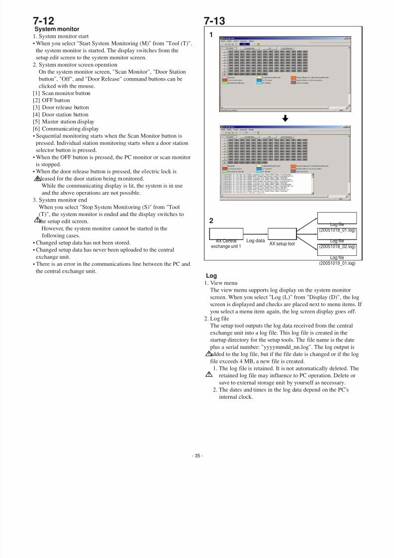
Log1. View menu
The view menu supports log display on the system monitor
screen. When you select "Log (L)" from "Display (D)", the lo
screen is displayed and checks are placed next to menu items.
you select a menu item again, the log screen display goes off.
2. Log file
The setup tool outputs the log data received from the central
exchange unit into a log file. This log file is created in the
startup directory for the setup tools. The file name is the date
plus a serial number: "yyyymmdd_nn.log". The log output is
added to the log file, but if the file date is changed or if the log
file exceeds 4 MB, a new file is created.1. The log file is retained. It is not automatically deleted. Th
retained log file may influence to PC operation. Delete or
save to external storage unit by yourself as necessary.
2. The dates and times in the log data depend on the PC's
internal clock.
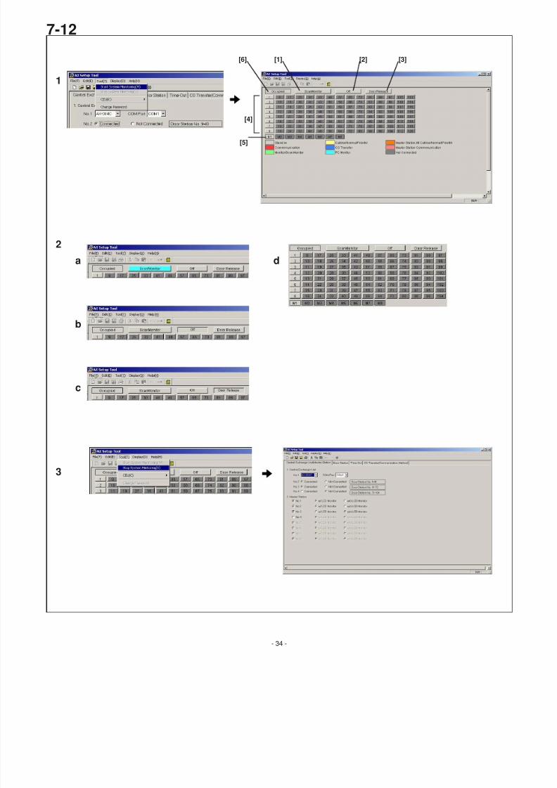
System monitor1. System monitor start
• When you select "Start System Monitoring (M)" from "Tool (T)",
the system monitor is started. The display switches from the
setup edit screen to the system monitor screen.
2. System monitor screen operation
On the system monitor screen, "Scan Monitor", "Door Station
button", "Off", and "Door Release" command buttons can be
clicked with the mouse.
[1] Scan monitor button
[2] OFF button
[3] Door release button
[4] Door station button
[5] Master station display
[6] Communicating display
• Sequential monitoring starts when the Scan Monitor button is
pressed. Individual station monitoring starts when a door station
selector button is pressed.
• When the OFF button is pressed, the PC monitor or scan monitor
is stopped.
• When the door release button is pressed, the electric lock is
released for the door station being monitored.While the communicating display is lit, the system is in use
and the above operations are not possible.
3. System monitor end
When you select "Stop System Monitoring (S)" from "Tool
(T)", the system monitor is ended and the display switches to
the setup edit screen.
However, the system monitor cannot be started in the
following cases.
• Changed setup data has not been stored.
• Changed setup data has never been uploaded to the central
exchange unit.
• There is an error in the communications line between the PC and
the central exchange unit.
Log data
Log file(20051018_01.log)
Log file(20051019_01.log)
Log file(20051018_02.log)
AX setup toolAX Central
exchange unit 1
1
2
7/29/2019 Aiphone Model AX Series - Install & Op Manual 0311- Westside Wholesale - Call 1-877-998-9378
http://slidepdf.com/reader/full/aiphone-model-ax-series-install-op-manual-0311-westside-wholesale-call 36/44
- 36 -
7-14 7-15
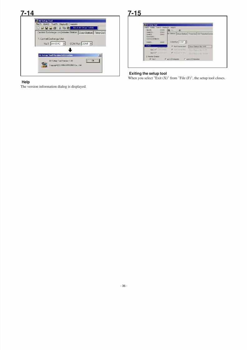
HelpThe version information dialog is displayed.
Exiting the setup toolWhen you select "Exit (X)" from "File (F)", the setup tool closes
7/29/2019 Aiphone Model AX Series - Install & Op Manual 0311- Westside Wholesale - Call 1-877-998-9378
http://slidepdf.com/reader/full/aiphone-model-ax-series-install-op-manual-0311-westside-wholesale-call 37/44
8-1
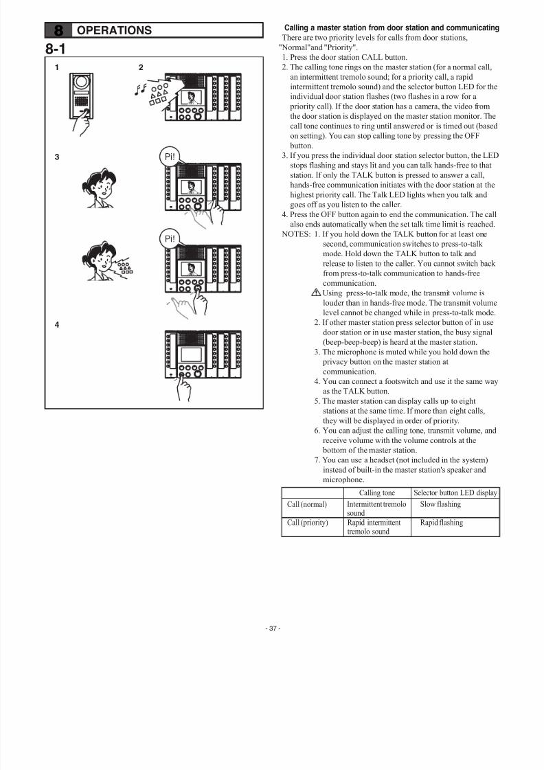
Calling a master station from door station and communicatinThere are two priority levels for calls from door stations,
"Normal"and "Priority".
1. Press the door station CALL button.
2. The calling tone rings on the master station (for a normal call,
an intermittent tremolo sound; for a priority call, a rapid
intermittent tremolo sound) and the selector button LED for th
individual door station flashes (two flashes in a row for a
priority call). If the door station has a camera, the video from
the door station is displayed on the master station monitor. Th
call tone continues to ring until answered or is timed out (baseon setting). You can stop calling tone by pressing the OFF
button.
3. If you press the individual door station selector button, the LE
stops flashing and stays lit and you can talk hands-free to that
station. If only the TALK button is pressed to answer a call,
hands-free communication initiates with the door station at th
highest priority call. The Talk LED lights when you talk and
goes off as you listen to the caller.
4. Press the OFF button again to end the communication. The ca
also ends automatically when the set talk time limit is reached
NOTES: 1. If you hold down the TALK button for at least one
second, communication switches to press-to-talk
mode. Hold down the TALK button to talk and
release to listen to the caller. You cannot switch bac
from press-to-talk communication to hands-free
communication.
Using press-to-talk mode, the transmit volume is
louder than in hands-free mode. The transmit volum
level cannot be changed while in press-to-talk mode
2. If other master station press selector button of in use
door station or in use master station, the busy signal
(beep-beep-beep) is heard at the master station.
3. The microphone is muted while you hold down the
privacy button on the master station at
communication.4. You can connect a footswitch and use it the same w
as the TALK button.
5. The master station can display calls up to eight
stations at the same time. If more than eight calls,
they will be displayed in order of priority.
6. You can adjust the calling tone, transmit volume, an
receive volume with the volume controls at the
bottom of the master station.
7. You can use a headset (not included in the system)
instead of built-in the master station's speaker and
microphone.
Selector button LED displCalling tone
Intermittent tremolosound
Rapid intermittenttremolo sound
Slow flashing
Rapid flashing
Call (normal)
Call (priority)
8 OPERATIONS
1 2
3
4
- 37 -
7/29/2019 Aiphone Model AX Series - Install & Op Manual 0311- Westside Wholesale - Call 1-877-998-9378
http://slidepdf.com/reader/full/aiphone-model-ax-series-install-op-manual-0311-westside-wholesale-call 38/44
8-2 8-3Privacy (PRIV)function
1. To make the master into privacy mode (prevent monitoring
from other stations), press the privacy button (LED lights up)
2. To cancel privacy mode, press the privacy button again (LED
goes out).
∗ The privacy setting cannot be changed while in communicatio
PRIV LEDPrivacy setting
Lit
Off
Setting up
Not set
Communicatingwith master station
• Microphone mute•†If you hold down the TALK button for at least one second,communication switches to
press-to-talk.
•†Microphone enabled• The microphone is muted whileyou hold down the PRIV button.
Communicatingwith door station
• Microphone enable• The microphone ismuted while you holdown the PRIV butto
• Microphone enable• The microphone ismuted while you holdown the PRIV butto
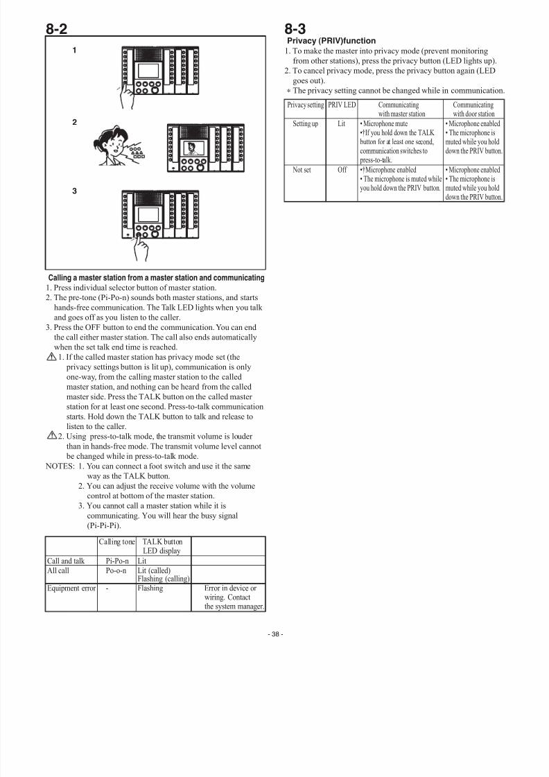
Calling a master station from a master station and communicating1. Press individual selector button of master station.
2. The pre-tone (Pi-Po-n) sounds both master stations, and starts
hands-free communication. The Talk LED lights when you talk
and goes off as you listen to the caller.
3. Press the OFF button to end the communication. You can end
the call either master station. The call also ends automatically
when the set talk end time is reached.
1. If the called master station has privacy mode set (the
privacy settings button is lit up), communication is only
one-way, from the calling master station to the calledmaster station, and nothing can be heard from the called
master side. Press the TALK button on the called master
station for at least one second. Press-to-talk communication
starts. Hold down the TALK button to talk and release to
listen to the caller.
2. Using press-to-talk mode, the transmit volume is louder
than in hands-free mode. The transmit volume level cannot
be changed while in press-to-talk mode.
NOTES: 1. You can connect a foot switch and use it the same
way as the TALK button.
2. You can adjust the receive volume with the volume
control at bottom of the master station.
3. You cannot call a master station while it iscommunicating. You will hear the busy signal
(Pi-Pi-Pi).
Calling tone TALK buttonLED display
Pi-Po-n
Po-o-n
-
Lit
Lit (called)Flashing (calling)Flashing Error in device or
wiring. Contactthe system manager.
Call and talk
All call
Equipment error
1
2
3
- 38 -
7/29/2019 Aiphone Model AX Series - Install & Op Manual 0311- Westside Wholesale - Call 1-877-998-9378
http://slidepdf.com/reader/full/aiphone-model-ax-series-install-op-manual-0311-westside-wholesale-call 39/44
- 39 -
8-4 8-5
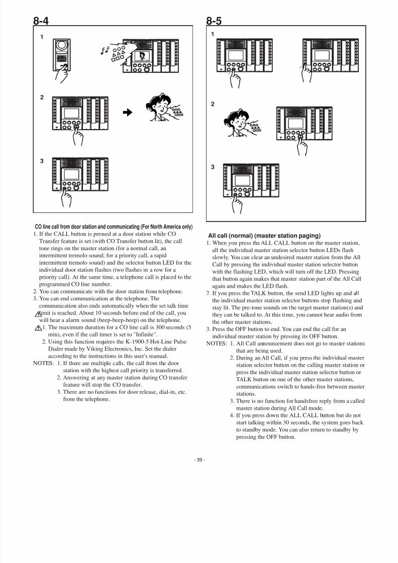
CO line call from door station and communicating (For North America only)1. If the CALL button is pressed at a door station while CO
Transfer feature is set (with CO Transfer button lit), the call
tone rings on the master station (for a normal call, an
intermittent tremolo sound; for a priority call, a rapid
intermittent tremolo sound) and the selector button LED for the
individual door station flashes (two flashes in a row for a
priority call). At the same time, a telephone call is placed to the
programmed CO line number.
2. You can communicate with the door station from telephone.
3. You can end communication at the telephone. The
communication also ends automatically when the set talk time
limit is reached. About 10 seconds before end of the call, you
will hear a alarm sound (beep-beep-beep) on the telephone.
1. The maximum duration for a CO line call is 300 seconds (5
min), even if the call timer is set to "Infinite".
2. Using this function requires the K-1900-5 Hot-Line Pulse
Dialer made by Viking Electronics, Inc. Set the dialer
according to the instructions in this user's manual.
NOTES: 1. If there are multiple calls, the call from the door station with the highest call priority is transferred.
2. Answering at any master station during CO transfer
feature will stop the CO transfer.
3. There are no functions for door release, dial-in, etc.
from the telephone.
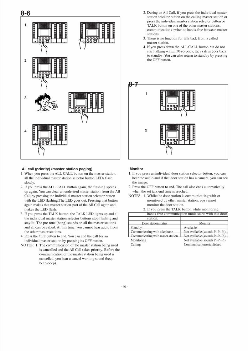
All call (normal) (master station paging)1. When you press the ALL CALL button on the master station,
all the individual master station selector button LEDs flash
slowly. You can clear an undesired master station from the All
Call by pressing the individual master station selector button
with the flashing LED, which will turn off the LED. Pressingthat button again makes that master station part of the All Call
again and makes the LED flash.
2. If you press the TALK button, the send LED lights up and all
the individual master station selector buttons stop flashing and
stay lit. The pre-tone sounds on the target master station(s) an
they can be talked to. At this time, you cannot hear audio from
the other master stations.
3. Press the OFF button to end. You can end the call for an
individual master station by pressing its OFF button.
NOTES: 1. All Call announcement does not go to master station
that are being used.
2. During an All Call, if you press the individual maste
station selector button on the calling master station press the individual master station selector button or
TALK button on one of the other master stations,
communications switch to hands-free between mast
stations.
3. There is no function for handsfree reply from a calle
master station during All Call mode.
4. If you press down the ALL CALL button but do not
start talking within 30 seconds, the system goes bac
to standby mode. You can also return to standby by
pressing the OFF button.
1
2
3
1
2
3
7/29/2019 Aiphone Model AX Series - Install & Op Manual 0311- Westside Wholesale - Call 1-877-998-9378
http://slidepdf.com/reader/full/aiphone-model-ax-series-install-op-manual-0311-westside-wholesale-call 40/44
- 40 -
8-6
8-7
Monitor1. If you press an individual door station selector button, you can
hear the audio and if that door station has a camera, you can s
the image.
2. Press the OFF button to end. The call also ends automatically
when the set talk end time is reached.
NOTES: 1. While the door station is communicating with or
monitored by other master station, you cannot
monitor the door station.
2. If you press the TALK button while monitoring,
hands-free communication mode starts with that do
station.
All call (priority) (master station paging)1. When you press the ALL CALL button on the master station,
all the individual master station selector button LEDs flash
slowly.
2. If you press the ALL CALL button again, the flashing speeds
up again. You can clear an undesired master station from the All
Call by pressing the individual master station selector button
with the LED flashing.The LED goes out. Pressing that button
again makes that master station part of the All Call again and
makes the LED flash.
3. If you press the TALK button, the TALK LED lights up and all
the individual master station selector buttons stop flashing and
stay lit. The pre-tone (bong) sounds on all the master stations
and all can be called. At this time, you cannot hear audio fromthe other master stations.
4. Press the OFF button to end. You can end the call for an
individual master station by pressing its OFF button.
NOTES: 1. The communication of the master station being used
is cancelled and the All Call takes priority. Before the
communication of the master station being used is
cancelled, you hear a cancel warning sound (beep-
beep-beep).
2. During an All Call, if you press the individual maste
station selector button on the calling master station
press the individual master station selector button or
TALK button on one of the other master stations,
communications switch to hands-free between mast
stations.
3. There is no function for talk back from a called
master station.
4. If you press down the ALL CALL button but do not
start talking within 30 seconds, the system goes bac
to standby. You can also return to standby by pressinthe OFF button.
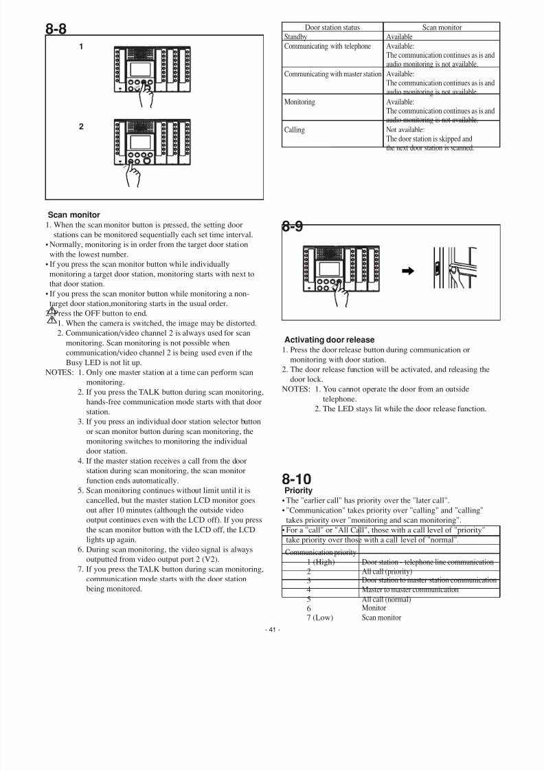
Monitor
AvailableNot available (sounds Pi-Pi-PiNot available (sounds Pi-Pi-Pi
Not available (sounds Pi-Pi-Pi
Communication established
Standby
Door station status
Communicating with telephoneCommunicating with maser station
Monitoring
Calling
1
2
3
4
1
2
7/29/2019 Aiphone Model AX Series - Install & Op Manual 0311- Westside Wholesale - Call 1-877-998-9378
http://slidepdf.com/reader/full/aiphone-model-ax-series-install-op-manual-0311-westside-wholesale-call 41/44
- 41 -
8-8
8-9Scan monitor
1. When the scan monitor button is pressed, the setting door
stations can be monitored sequentially each set time interval.
• Normally, monitoring is in order from the target door station
with the lowest number.
• If you press the scan monitor button while individually
monitoring a target door station, monitoring starts with next to
that door station.
• If you press the scan monitor button while monitoring a non-
target door station,monitoring starts in the usual order.
2. Press the OFF button to end.
1. When the camera is switched, the image may be distorted.
2. Communication/video channel 2 is always used for scan
monitoring. Scan monitoring is not possible when
communication/video channel 2 is being used even if the
Busy LED is not lit up.
NOTES: 1. Only one master station at a time can perform scanmonitoring.
2. If you press the TALK button during scan monitoring,
hands-free communication mode starts with that door
station.
3. If you press an individual door station selector button
or scan monitor button during scan monitoring, the
monitoring switches to monitoring the individual
door station.
4. If the master station receives a call from the door
station during scan monitoring, the scan monitor
function ends automatically.
5. Scan monitoring continues without limit until it is
cancelled, but the master station LCD monitor goesout after 10 minutes (although the outside video
output continues even with the LCD off). If you press
the scan monitor button with the LCD off, the LCD
lights up again.
6. During scan monitoring, the video signal is always
outputted from video output port 2 (V2).
7. If you press the TALK button during scan monitoring,
communication mode starts with the door station
being monitored.
Priority
• The "earlier call" has priority over the "later call".• "Communication" takes priority over "calling" and "calling"
takes priority over "monitoring and scan monitoring".
• For a "call" or "All Call", those with a call level of "priority"
take priority over those with a call level of "normal".
Communication priority
Door station - telephone line communication
All call (priority)Door station to master station communicatio
Master to master communication
1 (High)
234
All call (normal)Monitor
Scan monitor
567 (Low)
8-10
Activating door release1. Press the door release button during communication or
monitoring with door station.
2. The door release function will be activated, and releasing the
door lock.
NOTES: 1. You cannot operate the door from an outside
telephone.
2. The LED stays lit while the door release function.
Not available:The door station is skipped andthe next door station is scanned.
Calling
Available:The communication continues as is anaudio monitoring is not available.
Monitoring
Available:The communication continues as is anaudio monitoring is not available.
Communicating with master station
Available:The communication continues as is anaudio monitoring is not available.
Communicating with telephone
AvailableStandby
Scan monitor Door station status
1
2
7/29/2019 Aiphone Model AX Series - Install & Op Manual 0311- Westside Wholesale - Call 1-877-998-9378
http://slidepdf.com/reader/full/aiphone-model-ax-series-install-op-manual-0311-westside-wholesale-call 42/44
- 42 -
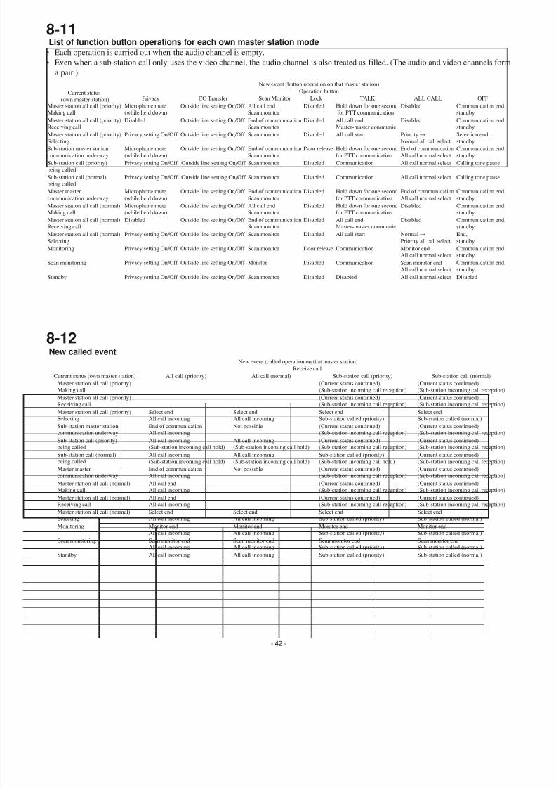
8-11List of function button operations for each own master station mode
• Each operation is carried out when the audio channel is empty.
• Even when a sub-station call only uses the video channel, the audio channel is also treated as filled. (The audio and video channels for
a pair.)
Current status
(own master station)Master station all call (priority)
Making call
Microphone mute
(while held down)
Microphone mute
(while held down)
Privacy setting On/Off
Privacy setting On/Off
Privacy setting On/Off
Privacy setting On/Off
Privacy setting On/Off
Microphone mute
(while held down)
Disabled
Privacy setting On/Off
Microphone mute
(while held down)
Disabled
Privacy setting On/Off
Privacy
Outside line setting On/Off
Outside line setting On/Off
Outside line setting On/Off
Outside line setting On/Off
Outside line setting On/Off
Outside line setting On/Off
Outside line setting On/Off
Outside line setting On/Off
Outside line setting On/Off
Outside line setting On/Off
Outside line setting On/Off
Outside line setting On/Off
Outside line setting On/Off
CO Transfer
End of communication
Scan monitor
End of communication
Scan monitor
Scan monitor
Monitor
Scan monitor
Scan monitor
Scan monitor
All call end
Scan monitor
End of communication
Scan monitor Scan monitor
All call end
Scan monitor
End of communication
Scan monitor
Scan monitor
Scan Monitor
Door release
Disabled
Door release
Disabled
Disabled
Disabled
Disabled
Disabled
Disabled
Disabled
Disabled
Disabled
Disabled
Lock
New event (button operation on that master station)
Operation button
Communication end
standby
Communication end
standby
Communication end
standbyCommunication end
standby
Disabled
Calling tone pause
Calling tone pause
Communication end
standby
Communication end
standbySelection end,
standby
Communication end
standby
Communication end
standby
End,
standby
OFF
End of communication
All call normal select
End of communication
All call normal select
Monitor end
All call normal selectScan monitor endAll call normal select
All call normal select
All call normal select
All call normal select
Disabled
Disabled
PriorityǞ
Normal all call select
Disabled
Disabled
NormalǞ
Priority all call select
ALL CALL
Hold down for one second
for PTT communication
Hold down for one second
for PTT communication
Communication
Communication
Disabled
Communication
Communication
Hold down for one second
for PTT communication
TALK
All call end
Master-master communicAll call start
Hold down for one second
for PTT communication
All call end
Master-master communic
All call start
Master station all call (priority)
Receiving callMaster station all call (priority)
Selecting
Sub-station master station
communication underway
Sub-station call (priority)
being called
Sub-station call (normal)
being called
Master master
communication underway
Master station all call (normal)
Making call
Master station all call (normal)
Receiving call
Master station all call (normal)
Selecting
Monitoring
Scan monitoring
Standby
8-12New called event
Current status (own master station)
Sub-station master station
communication underway
Master master
communication underway
Monitoring
Scan monitoring
Standby
Sub-station call (priority)
being called
Sub-station call (normal)being called
Master station all call (priority)Making call
Master station all call (priority)
Receiving call
Master station all call (priority)Selecting
Master station all call (normal)
Making call
Master station all call (normal)
Receiving call
Master station all call (normal)Selecting
End of communication
All call incoming
End of communication
All call incoming
Monitor end
All call incoming
Scan monitor end
All call incoming
All call incoming
All call incoming
(Sub-station incoming call hold)
All call incoming
(Sub-station incoming call hold)
Select end
All call incoming
All call end
All call incoming
All call end
All call incoming
Select endAll call incoming
All call (priority)
Monitor end
All call incoming
Scan monitor end
All call incoming
All call incoming
Not possible
Not possible
All call incoming
(Sub-station incoming call hold)
All call incoming
(Sub-station incoming call hold)
Select end
All call incoming
Select endAll call incoming
All call (normal)
(Current status continued)
(Sub-station incoming call reception)
(Current status continued)
(Sub-station incoming call reception)
Monitor end
Sub-station called (priority)
Scan monitor end
Sub-station called (priority)
Sub-station called (priority)
(Current status continued)
(Sub-station incoming call reception)
Sub-station called (priority)
(Sub-station incoming call hold)
(Current status continued)(Sub-station incoming call reception)
(Current status continued)
(Sub-station incoming call reception)
Select end
Sub-station called (priority)
(Current status continued)
(Sub-station incoming call reception)
(Current status continued)
(Sub-station incoming call reception)
Select endSub-station called (priority)
Sub-station call (priority)
(Current status continued)
(Sub-station incoming call reception
(Current status continued)
(Sub-station incoming call reception
Monitor end
Sub-station called (normal)
Scan monitor end
Sub-station called (normal)
Sub-station called (normal)
(Current status continued)
(Sub-station incoming call reception
(Current status continued)
(Sub-station incoming call reception
(Current status continued)(Sub-station incoming call reception
(Current status continued)
(Sub-station incoming call reception
Select end
Sub-station called (normal)
(Current status continued)
(Sub-station incoming call reception
(Current status continued)
(Sub-station incoming call reception
Select endSub-station called (normal)
Sub-station call (normal)
New event (called operation on that master station)
Receive call
7/29/2019 Aiphone Model AX Series - Install & Op Manual 0311- Westside Wholesale - Call 1-877-998-9378
http://slidepdf.com/reader/full/aiphone-model-ax-series-install-op-manual-0311-westside-wholesale-call 43/44
- 43 -
9 TECHNICAL PRECAUTIONS
Technical precautions• Operating temperature:
Door station: -10 ~ 60 °C (14 ~ 140 °F)
Master station: 0 ~ 40 °C (32 ~ 104 °F)
Central exchange unit: 0 ~ 40 °C (32 ~ 104 °F)
• Cleaning: Clean the units with a soft cloth dampened with a
neutral household cleanser. Do not use an abrasive
cleaner or cloth.
• Camera switching:Since the individual camera sync signal is a non-
synchronized signal, the image synchronization may
be disrupted. Also, the time until synchronization is
re-established depends on the display device used.
Specifications•Power supply: DC 24 V, 2 A
(Two Power supply required per video system
•Current consumption:
AX-084C: Video (Max.) 650 mA, Audio (Max.) 700 mA
AX-248C: Video (Max.) 1150 mA, Audio (Max.) 1250 mA
AX-320C: Video (Max.) 280 mA, Audio (Max.) 180 mA
•Communication: <Auto> VOX
<Manual> Press-to-talk, Release-to-liste•Camera: CCD 250,000 pixels
•Video monitor: 3-1/2" direct view TFT color LCD
•Scanning lines: 525 lines.
•Door release contact: 24 V AC/DC, 0.5 A
•Dimensions:
AX-DM: 43(W) x 160(H) x 22.5(D) mm
1-11/16"W x 6-5/16"H x 7/8"D
AX-DV: 100(W) x 195(H) x 25(D) mm
3-15/16"W x 7-11/16"H x 1"D
AX-DVF: 146(W) x 246(H) x 47(D) mm
5-3/4"W x 9-11/16"H x 1-7/8"D
AX-DV-P: 100(W) x 245(H) x 25(D) mm
3-15/16"W x 9-5/8"H x 1"DAX-DVF-P: 146(W) x 295(H) x 47(D) mm
5-3/4"W x 11-5/8"H x 1-7/8"D
AX-8M: 194(W) x 175(H) x 48(D) mm
7-5/8"W x 6-7/8"H x 1-7/8"D
AX-8MV: 194(W) x 175(H) x 48(D) mm
7-5/8"W x 6-7/8"H x 1-7/8"D
AX-16SW: 86(W) x 175(H) x 48(D) mm
3-3/8"W x 6-7/8"H x 1-7/8"D
AX-084C: 480(W) x 88(H) x 335(D) mm
1'6-7/8"W x 3-7/16"H x 1'1-3/16"D
AX-248C: 480(W) x 88(H) x 335(D) mm
1'6-7/8"W x 3-7/16"H x 1'1-3/16"D
AX-320C: 480(W) x 88(H) x 335(D) mm
1'6-7/8"W x 3-7/16"H x 1'1-3/16"D
•Weight:
AX-DM: 100g (0.22 lbs.) approx.
AX-DV: 400g (0.88 lbs.) approx.
AX-DVF: 660g (1.45 lbs.) approx.
AX-DV-P: 450g (0.99 lbs.) approx.
AX-DVF-P: 760g (1.67 lbs.) approx.
AX-8M: 450g (0.99 lbs.) approx.
AX-8MV: 550g (1.21 lbs.) approx.
AX-16SW: 200g (0.44 lbs.) approx.
AX-084C: 4,700g (10.35 lbs.) approx.
AX-248C: 4,700g (10.35 lbs.) approx.AX-320C: 4,700g (10.35 lbs.) approx.
• Central exchange unit (AX-084C, 248C):
Outside video output: NTSC standard 1 Vpp (0.7-1.4 Vpp)
BNC(2)
Outside video output unit: Open collector output
DC24V, 30mA
RJ45(2)
•Master station (AX-8MV):
Outside video output: NTSC standard 1 Vpp (0.7-1.4 Vpp)
10 SPECIFICATIONS
7/29/2019 Aiphone Model AX Series - Install & Op Manual 0311- Westside Wholesale - Call 1-877-998-9378
http://slidepdf.com/reader/full/aiphone-model-ax-series-install-op-manual-0311-westside-wholesale-call 44/44
Aiphone warrants its products to be free from defects of material and workmanshipunder normal use and service for a period of two years after delivery to the ultimate user and will repair free of charge or replace at no charge, should it become defective uponwhich examination shall disclose to be defective and under warranty. Aiphone reservesunto itself the sole right to make the final decision whether there is a defect in materialsand/or workmanship; and whether or not the product is within the warranty. Thiswarranty shall not apply to any Aiphone product which has been subject to misuse,neglect, accident, or to use in violation of instructions furnished, nor extended to unitswhich have been repaired or altered outside of the factory. This warranty does not cover batteries or damage caused by batteries used in connection with the unit. This warrantycovers bench repairs only,and any repairs must be made at the shop or place designatedin writing by Aiphone. Aiphone will not be responsible for any costs incurred involvingon site service calls. Aiphone will not provide compensation for any loss or damageincurred by the breakdown or malfunction of its products during use, or for anyconsequent inconvenience or losses that may result.
WARRANTY
FCC REQUIREMENTSThis equipment has been tested and found to comply with the limits for a Class B digitaldevice, pursuant to Part 15 of the FCC Rules. These limits are designed to providereasonable protection against harmful interference in a residential installation. Thisequipment generates, uses, and can radiate radio frequency energy, and if not installedand used in accordance with the instructions, may cause harmful interference to radiocommunications. However, there is no guarantee that interference will not occur in aparticular installation. If this equipment does cause harmful interference to radio or television reception, which can be determined by turning the equipment off and on, theuser is encouraged to try to correct the interference by one or more of the followingmeasures: • Reorient or relocate the receiving antenna • Connect the equipment into anoutlet on a circuit different from that to which the receiver is connected. Increase theseparation between the equipment and receiver. • Consult the dealer or an experiencedradio/TV technician for help.