Embed Size (px)
Citation preview

SS66 SPLIT SHAFT PTO INSTALLATION INSTRUCTIONS
Muncie Power Products, Inc.
The Muncie Split Shaft PTOModel SS66-U2X3-A00XXX
(As shown, less PTO’s)

2
APPLICATION INFORMATION
THROUGHPUT TORQUE: 2900 FT-LBS [400 KGM]Calculating Throughput Torque: Multiply Max engine torque by the deepest transmission ratio.Example: Ford Super Duty F-450Engine = 7.3L Diesel Engine 235GHP @ 2600 RPM 500 Ft-Lbs @ 1800 RPMTransmission = ZF S6-650 6 Speed OD
Through Torque = 500 Ft-Lbs X 5.79 Ratio = 2,895 Ft-Lbs
MAXIMUM PTO TORQUE: 289 FT-LBSThe SS66 PTO drive gear has a maximum rated torque of 289 Ft-Lbs. PTO input gear loads must not exceed this value regardless of the number of PTOs used. PTO applications are limited to intermittent application only.
PTO TypeSplit Shaft — SS
PTO Series6-Bolt Opening (U60) – 66
Torque Rating2900 Ft-Lbs – U2Base Unit: 3258010300 Air (SS66)3258020300 Cable (SS66)
Main Shaft Flange Selection1410 (Kit: 2053740000) – X21480, 1550 (Kit: 2053750000) – X3
Special FeaturesX — None
Special OptionsXX — None
PTO Mounting00 — Both Openings Open0X — #1 Open, #2 CoveredX0 — #1 Covered, #2 OpenXX — Both Sides Covered(Cover Kit: 2990230000)
Shifter TypeA — Manual Air 12V (48TK4428)C — Cable Control (Cable not incl.)* (28TK4426 Mtg Kit)E — Electric/Air 12V(48TK4430)
*Order Control Cable Separately 55 Series, 2” Travel, Bulkhead Mount. Example: KB55-BM-2-XXX
MODEL NUMBER CONSTRUCTIONSS 66 – U2 X3 – A 00 XX X
1st 2nd 3rd 4th 5th 6th Rev 5.79 3.31 2.10 1.31 1.00 0.72 5.23
3
SPLIT-SHAFT INSTALLATION
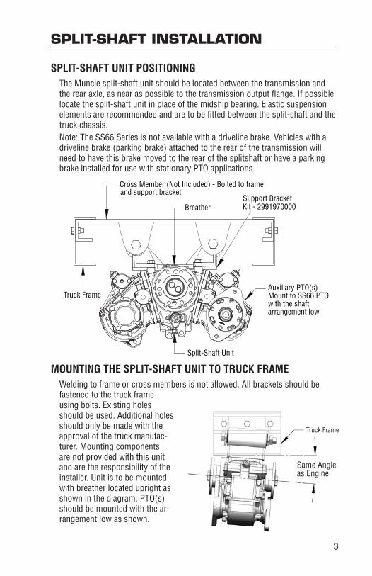
SPLIT-SHAFT UNIT POSITIONINGThe Muncie split-shaft unit should be located between the transmission and the rear axle, as near as possible to the transmission output flange. If possible locate the split-shaft unit in place of the midship bearing. Elastic suspension elements are recommended and are to be fitted between the split-shaft and the truck chassis. Note: The SS66 Series is not available with a driveline brake. Vehicles with a driveline brake (parking brake) attached to the rear of the transmission will need to have this brake moved to the rear of the splitshaft or have a parking brake installed for use with stationary PTO applications.
MOUNTING THE SPLIT-SHAFT UNIT TO TRUCK FRAMEWelding to frame or cross members is not allowed. All brackets should be fastened to the truck frame using bolts. Existing holes should be used. Additional holes should only be made with the approval of the truck manufac-turer. Mounting components are not provided with this unit and are the responsibility of the installer. Unit is to be mounted with breather located upright as shown in the diagram. PTO(s) should be mounted with the ar-rangement low as shown.
Cross Member (Not Included) - Bolted to frame and support bracket
BreatherSupport BracketKit - 2991970000
Truck FrameAuxiliary PTO(s)Mount to SS66 PTOwith the shaftarrangement low.
Split-Shaft Unit

4
OIL LEVELSplit Shaft must be filled with oil up to fill level plug before use. Remove fill plug and fill unit to this level with SAE 90 EP gearbox oil. Replace plug. Check oil level regularly every two weeks.
SPLIT-SHAFT INSTALLATION
DRIVE SHAFTSContact your local Driveline shop for driveshafts and driveshaft alterations. All shafts used in the vehicle’s driveline should be the same size and quality as the original ones. The same applies to flanges, bolts, and nuts. Self-locking nuts should never be used twice and should be replaced by new ones.Balance - All drive shafts should be statically and dynamically balanced.Angles - To prevent vibration and noise during operation all drive flanges must be parallel. Therefore it is necessary to incline the split-shaft unit and all other driven equipment at the same angle to the truck frame as the transmission. This angle varies with the truck model. Information should be obtained from the truck manufacturer. Phase - Drivelines with slip joints should be used. Make sure enough compen-sation is allowed for length changes. When assembling, make sure all U-joints are correctly phased by ensuring that index markings are correctly aligned.Protection - For safety reasons it is highly recommended to provide all acces-sible Drivelines with protection covers.
4.50°
Truck Frame
GearBox
Sliding Joint
SS66 PTO
Yokes In Phase
Mounting Angle
Rear Axle
Yokes In Phase
Flanges Should Be Parallel
Sliding Joint
PTO axis should be parallelto the axis of the gearbox
Gearbox Axis

5
DIMENSIONAL INFORMATION
SS66 PTO
0.83[21]
[199]7.83
[224]8.82
[162]6.38
[31]1.22
5.63[142.9]
[21]0.83
Stroke
SIDE VIEW
BOTTOM VIEW
REAR VIEW
TOP VIEW
30°
3.03[76.9]
3.03[76.9]
2.60[66]
3.54[90]4.80
[122]
0.98[24.9]
7.40[188]
Ø 0.51[13]
Oil Level Fill Plug
3.31[84]
2.76[70]
M12
3.94[100]
Drain Plug
1.40[35.5]
0.98[25]
3.54[90]
5.67[144]
M12
FRONT OF VEHICLE

6
MAIN SHAFT FLANGES
1410/DIN 20 FLANGE
1480/1550 FLANGE
Ø 4.72[120]
Ø 2.75[69.9]
0.08[2] 0.31
[8]
Ø 2.95[75]
80°
Ø 3.75 (1410)[95.3]
Ø 4.00 (Din 20)[101.6]
Ø .48[12.3]
Ø .40[10.3]
Ø 5.79[147]
Ø 3.75[95.3]
0.12[3] 0.39
[10]
Ø 4.75[120.7]
80.00°80.00°
Ø 0.50[12.7] [14.2]
Ø 0.56
PROFILE VIEW
PROFILE VIEW
FRONT VIEW
FRONT VIEW

7
SUPPORT BRACKET
OPTIONAL KIT — 2991970000
5.67[144]
5.28[134]
1.77[45]
1.77[45]
1.77[45]
1.77[45]
2.64[67]
2.64[67]
Ø 0.64[16.2]

8
SS66 INSTALLATION KITS
SS66 Housing SS66 Housing1/8" NPT
1/4" ID Tubing
MANUAL AIR 12V: “A” OPTION — 48TK4985
SS66 ACTIVATION KIT INSTALLATION
To Truck Air Supply Tank
SS66 Split Shaft
11 11
12V DC Battery
3 4
Ground
12 7
1
9
32
10
6
88
13
5
NOTE: Connect directly to the air tank. Do not use hose or tubing.
From Port 2From Port 1
From Port 4
Port 1Port R
Port 2
Port 3
Port 4To Battery
To Pressure Switch
BACK OF VALVE ASSEMBLY
14
16
15
17
AIR VALVE ASSEMBLY
ITEM QTY PART NO. DESCRIPTIONACTIVATION KIT 48TK4985
1 1 30T37954 Pressure Switch2 1 44MB2252 Fitting3 2 44MB6842 Fitting4 1 44T35791 Fitting5 1 34T36941 Pig Tail
ACTIVATION KIT 48M61261A (included in 48TK4985)6 1 31M15759 Pressure Protection Valve7 1 33T36299 Fuse Assembly8 1 45M44430 Air Tubing (0.25" x 30 ft.)9 1 44MB2164 1/4" N.P.T. Nipple
ITEM QTY PART NO. DESCRIPTION10 1 44MB6844 Tube Fitting11 2 44MB6942 Tube Fitting (Elbow)12 3 34M18002 End Crimp13 12.5' 37M18000 Electrical Wire14 1 35T37955 Air Valve15 1 32M12001 PTO Light - 12VDC16 1 36T38049 Dash Bracket17 1 36T38016 Face Plate
N.S. 1 34T38163 Booted ConnectorN.S. 1 36MK1007 Bolt Kit
9
SS66 INSTALLATION KITS
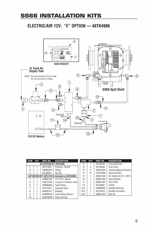
ELECTRIC/AIR 12V: “E” OPTION — 48TK4986
16
17
18
DASH BRACKET
ITEM QTY PART NO. DESCRIPTIONACTIVATION KIT 48TK4986
1 1 30T37954 Pressure Switch2 1 44MB2252 Fitting3 1 34T36941 Pig Tail
ACTIVATION KIT 48T37421A (included in 48TK4986)4 1 44MB2164 1/4" N.P.T. Nipple5 1 31M15759 Pressure Protection Valve6 1 44MB6844 Tube Fitting7 1 35T41078 Solenoid Valve8 2 44M30137 Breather9 2 44MB6942 Tube Fitting (Elbow)10 1 34M18009 Ring Terminal
ITEM QTY PART NO. DESCRIPTION11 1 33T36299 Fuse Assembly12 3 34T36362 End Crimp13 3 34M18250 Female Spade Connector14 12' 37M18000 Electrical Wire15 1 45M44430 Air Tubing (0.25" x 30 ft.)16 1 36MA1005 Dash Bracket17 1 36M01007 Face Plate18 1 30T35687 Switch
N.S. 2 44MB0942 Adapter BushingN.S. 1 34T38163 Booted ConnectorN.S. 1 36MK1007 Bolt Kit
NOTE: Connect directly to the air tank. Do not use hose or tubing.
4
58
Ground
8
Ground
6
7
2
1
6
9
6
SS66 Split Shaft
12V DC Battery
11
12 13
15
14
9
To Truck AirSupply Tank
310

10
ENGAGING THE SPLIT SHAFT PTO1. Stop the vehicle and put the transmission in neutral.2. Apply the parking brake and block wheels (if the unit is to operate while
the vehicle is stationary).3. For stationary operation: Shift the main shaft air control (double acting) to
disconnect the drive to the rear axle.4. With the engine at idle, engage the required PTO output(s) by operating
the relevant air control(s).5. Depress the clutch pedal and select the required gear. The output shaft
speeds are dependent on the main transmission gear selection. Use cau-tion if placing the transmission into reverse as it may cause damage to the driven component(s).
6. Slowly release the clutch pedal. If Split Shaft is not disengaged from the rear axle, release parking brake to allow vehicle to be driven at application rate.
7. For stationary operation: Set the engine speed to the required R.P.M.
DISENGAGING THE SPLIT SHAFT1. Return the engine speed to idle.2. Depress the clutch pedal and place the transmission in neutral.3. Set the parking brake if vehicle has been used in mobile application.4. Disengage the PTO output(s) by operating the relevant air control(s).5. Shift the main air control (double acting) to re-engage the drive to the rear
axle.6. Remove the wheel blocks, if stationary application.7. All PTO outputs are now disengaged. The vehicle can be driven as normal.
ENGAGING THE SPLIT SHAFT PTO1. Stop the vehicle and put the transmission in neutral.2. Apply the parking brake and block wheels (if the unit is to operate while
the vehicle is stationary).3. For stationary operation: Shift the main shaft air control (double acting) to
disconnect the drive to the rear axle.4. Engage the required PTO output(s) by operating the relevant air control(s).5. Shift transmission into the required gear selection. Use caution if plac-
ing the transmission into reverse as it may cause damage to the driven component(s).
MANUAL TRANSMISSION
AUTOMATIC TRANSMISSION

11
6. Stationary application: Using a method specified by the transmission manufacturer, shift transmission into direct drive.
Mobile application: If Split Shaft is not disengaged from the rear axle, release parking brake to allow vehicle to be driven at application rate.
7. For stationary operation: Set the engine speed to the required R.P.M.
DISENGAGING THE SPLIT SHAFT1. Be sure vehicle is stopped and apply parking brake.2. Shut off the engine with transmission in drive mode.3. Set the parking brake if vehicle has been used in mobile application.4. Disengage the PTO output(s) by operating the relevant air control(s).5. Shift transmission into neutral. 6. Remove the wheel blocks.7. Restart the engine.8. Shift the main air control (double acting) to re-engage the drive to the rear
axle.9. All PTO outputs are now disengaged. The vehicle can be driven as normal.
Failure to follow proper shifting or operating sequences will result in premature PTO failure with possible damage to the equipment.
AUTOMATIC TRANSMISSION

POWER TAKE-OFF WARRANTYThe Muncie Power Take-Off is warranted to be free of defects in material or workmanship and to meet Muncie’s standard written specifications at the time of sale. Muncie’s obligation and liability under this warranty is expressly limited to repairing or replacing, at Muncie’s option, within one year after date of original installation any defective part or parts or any product not meeting the specifications.
THIS WARRANTY IS IN LIEU OF ALL OTHER WARRANTIES, EXPRESSED OR IMPLIED. MUNCIE MAKES NO WARRANTY OF MERCHANTABILITY OR OF FITNESS FOR ANY PARTICULAR PURPOSE. MUNCIE’S OBLIGA-TION UNDER THIS WARRANTY SHALL NOT INCLUDE ANY TRANSPOR-TATION CHARGES OR COSTS OF INSTALLATION OR ANY LIABILITY FOR DIRECT, INDIRECT SPECIAL, INCIDENTAL, OR CONSEQUENTIAL DAM-AGES OR DELAY. THE REMEDIES SET FORTH HEREIN ARE EXCLUSIVE, AND MUNCIE’S LIABILITY WITH RESPECT TO ANY CONTRACT OR SALE OR ANYTHING DONE IN CONNECTION THEREWITH, WHETHER IN CON-TRACT, IN TORT, UNDER ANY WARRANTY, OR OTHERWISE, SHALL NOT, EXCEPT AS EXPRESSLY PROVIDED HEREIN, EXCEED THE PRICE OF THE PRODUCT OR PART ON WHICH SUCH LIABILITY IS BASED.
If requested by Muncie, products or parts for which a warranty claim is made are to be returned transportation prepaid to a Muncie Service Cen-ter. Any installation or use not in accordance with catalogue or package instructions, other improper use, operation beyond capacity, substitution of parts not approved by Muncie, use with equipment other than the equipment on which the Power Take-Off is first installed, or alteration or repair made to the Power Take-Off other than at a Muncie Service Center shall void this warranty. No employee or representative of Muncie is authorized to change this warranty in any way or to grant any other warranty.
Muncie Power Products, Inc. Member of the Interpump Hydraulics GroupGeneral Offices and Distribution Center • P.O. Box 548 • Muncie, IN 47308-0548 • (765) 284-7721FAX (765) 284-6991 • E-mail [email protected] • Web site http://www.munciepower.comDrive Products, Exclusive Agents for Canada, ISO Certified by an Accredited Registrar
IN01-02 (Rev. 4-10) Printed in the U.S.A.© Muncie Power Products, Inc. 2010