Embed Size (px)
Citation preview

MUNCIE POWER PRODUCTS, INC.
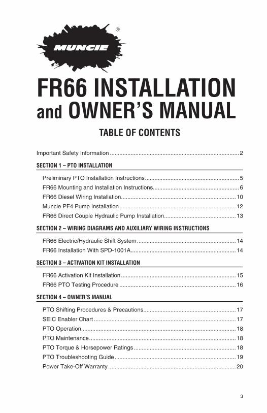
FR66 INSTALLATION and OWNER’S MANUAL
KEEP IN VEHICLEREAD OPERATING INSTRUCTIONSINSIDE BEFORE OPERATING PTO

2
WARNINGAlways read and understand the entire manual completely before installation or operation of pto and driven equipment including these warnings and operator’s
instructions in section 3!
ALWAYS disengage the PTO when the driven equipment is not in operation.
NEVER attempt to install or service any power take-off with the truck engine running. Put ignition keys in your pocket before getting under truck.
NEVER allow truck engine to be started while workers are under truck.
ALWAYS place transmission in neutral or park, set brakes, and immobilize truck wheels with suitable chocks, before working on a vehicle.
ALWAYS block any raised body or mechanism before working on or under equipment.
NEVER shift any installed power take-offs in or out of gear by any means except by the controls in the cab of the truck.
ALWAYS stay clear of spinning driveshafts to avoid becoming entangled and injured.
It shall be the responsibility of the installer of a Muncie power take-off to decide whether to install guards in the PTO and/or driveline area because of potential exposure to danger. This is because most Muncie PTOs are installed by equipment distributors or manufacturers and therefore, the responsibility of the installation is beyond the control of Muncie Power Products.
ALWAYS obtain proper training before operating this machinery.
NEVER install or operate equipment which has not been properly specified for your vehicle
Installers are to ensure that PTO components do not interfere with any chassis components, including but not limited to vehicle crossmembers, frame rails, driveshafts, exhausts, converters, fuel lines, etc. while vehicle is stationary or mobile.
ALWAYS allow the vehicle, PTO and driven equipment to warm up when op-erating in weather where temperatures are near or below freezing 32° f (0° c)
Install separate controls for pto and driven equipment.
ALWAYS install the safety labels provided and place the owner’s manual in the vehicle glove compartment.
The PTO is supplied with a packet containing warning labels. If you did not receive any, or if you need extra, you may order them, no charge, by phone, email or mail. They are available through your nearest Muncie® distributor or at the number and address below:
1-800-FOR-PTOS (1-800-367-7867)Muncie Power Products, Inc.
P.O. Box 548 Muncie, IN [email protected]
© Muncie Power Products, Inc. 2010
THIS SYMBOL WARNS OF
PERSONAL INJURY OR DEATH.
3
TABLE OF CONTENTS
Important Safety Information ................................................................................. 2
SECTION 1 – PTO INSTALLATION
Preliminary PTO Installation Instructions ........................................................... 5
FR66 Mounting and Installation Instructions ...................................................... 6
FR66 Diesel Wiring Installation ........................................................................ 10
Muncie PF4 Pump Installation ......................................................................... 12
FR66 Direct Couple Hydraulic Pump Installation ............................................. 13
SECTION 2 – WIRING DIAGRAMS AND AUXILIARY WIRING INSTRUCTIONS
FR66 Electric/Hydraulic Shift System .............................................................. 14
FR66 Installation With SPD-1001A .................................................................. 14
SECTION 3 – ACTIVATION KIT INSTALLATION
FR66 Activation Kit Installation ........................................................................ 15
FR66 PTO Testing Procedure ......................................................................... 16
SECTION 4 – OWNER’S MANUAL
PTO Shifting Procedures & Precautions .......................................................... 17
SEIC Enabler Chart ......................................................................................... 17
PTO Operation ................................................................................................. 18
PTO Maintenance ............................................................................................ 18
PTO Torque & Horsepower Ratings ................................................................ 18
PTO Troubleshooting Guide ............................................................................ 19
Power Take-Off Warranty ................................................................................ 20
FR66 INSTALLATION and OWNER’S MANUAL

4
SECTION - 1 PTO INSTALLATION
ALL INSTALLERS MUST READ THE FOLLOWING
PTO AND ACTIVATION KIT INSTALLATION INSTRUCTIONS Always wear safety glasses. Read entire manual before starting installation.
IMPORTANT: Disconnect vehicle battery prior to installing electrical and electric/hydraulic activation kits.
A. Vehicle manufacturers may have specific locations for accessing electri-cal power and activating hydraulics. The body builder manual or company representative for the vehicle chassis should be contacted prior to installing electrical or hydraulic systems.
B. Route wires and activation lines away from rotating and high temperature components. Use appropriate looms and bulk head pass-thru’s wherever possible to avoid rubbing through insulation or tubing and causing an electri-cal short or oil leak.
C. Follow all Federal Motor Vehicle Safety Standards (FMVSS) for your vehicle.
D. Where electrical grounds are indicated, be sure that they are good grounds, with straight paths to the vehicle battery ground. (Many vehicle cabs are in-sulated from the vehicle frame and a weak ground is a very common cause for malfunctions).
E. When installing hydraulic components, be certain to follow common installa-tion and testing procedures. If you are not familiar with acceptable instal-lation procedures request instructions and guidance from the hydraulic equipment supplier.
F. Caution should be taken by installer with any PTO installation to ensure components do not interfere with any chassis component during installation or when vehicle is operated.
G. Cold weather start conditions require that the transmission be started and warmed prior to engaging PTO and using equipment. Hydraulic pumps should be run at idle and under no load conditions to allow oil to warm be-fore activating hydraulic system.
IMPORTANT INFORMATION:
There is valuable information contained in the Ford “Super Duty F-Series Body Builders Layout Book”. You can obtain a copy of this book by faxing your request to “Body Builder Coordinator” at 1-734-414-2971. Include your street address and desired vehicle and model year. It can also be found on the Ford website at: http://www.fleet.ford.com/truckbbas/

5
INSTALLATION INSTRUCTIONS Always wear safety glasses. Read entire manual before starting installation.
1. There is a packet with the FR66 PTO which contains four (4) warning la-bels. Before adhering the labels, make sure the surfaces are free of dirt and grease. Place the labels supplied with the FR66 as follows:
TRUCK FRAME LABELS
The two (2) Truck Frame Labels, which measure approximately 4” x 8”, are to be placed on the outside of the vehicle frame rail. These labels are to be easily seen by anyone who might go under the truck or near the FR66 PTO. One label is to be placed on each side of the vehicle. See figure 1.
Note: Should the vehicle body installed on the chassis cover the frame rail, place the label on the body in a position easily visible by anyone who might go under the vehicle or near the FR66 PTO.
DO NOT PAINT OVER THE LABELS.
Figure 1
You may behurt or killed.
NEVER GET UNDER THIS TRUCK IF
THE ENGINE IS RUNNING!
¡NUNCA SE META DEBAJO DEL CAMIÓN CUANDA EL MOTOR ESTÉ EN MARCHA! Part No. 36M35644 (Rev. 9-06)
© Muncie Power Products, Inc. 2006
6
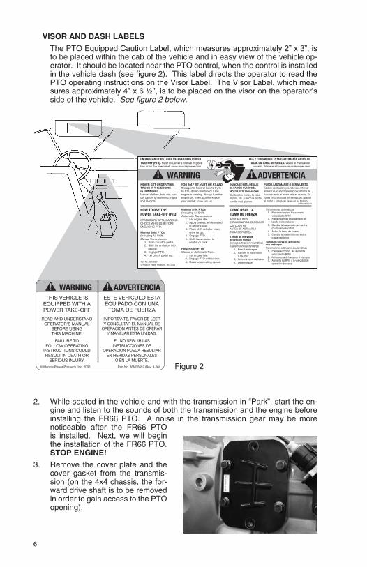
VISOR AND DASH LABELS
The PTO Equipped Caution Label, which measures approximately 2” x 3”, is to be placed within the cab of the vehicle and in easy view of the vehicle op-erator. It should be located near the PTO control, when the control is installed in the vehicle dash (see figure 2). This label directs the operator to read the PTO operating instructions on the Visor Label. The Visor Label, which mea-sures approximately 4” x 6 ½”, is to be placed on the visor on the operator’s side of the vehicle. See figure 2 below.
2. While seated in the vehicle and with the transmission in “Park”, start the en-gine and listen to the sounds of both the transmission and the engine before installing the FR66 PTO. A noise in the transmission gear may be more noticeable after the FR66 PTO is installed. Next, we will begin the installation of the FR66 PTO. STOP ENGINE!
3. Remove the cover plate and the cover gasket from the transmis-sion (on the 4x4 chassis, the for-ward drive shaft is to be removed in order to gain access to the PTO opening).
THIS VEHICLE ISEQUIPPED WITH APOWER TAKE-OFF
READ AND UNDERSTAND OPERATOR'S MANUAL
BEFORE USING THIS MACHINE.
FAILURE TO FOLLOW OPERATING
INSTRUCTIONS COULD RESULT IN DEATH OR
SERIOUS INJURY.
ESTE VEHICULO ESTAEQUIPADO CON UNA
TOMA DE FUERZA
IMPORTANTE. FAVOR DE LEER Y CONSULTAR EL MANUAL DE
OPERACION ANTES DE OPERAR Y MANEJAR ESTA UNIDAD.
EL NO SEGUIR LAS INSTRUCCIONES DE
OPERACION PUEDA RESULTAR EN HERIDAS PERSONALES
O EN LA MUERTE.© Muncie Power Products, Inc. 2006 Part No. 36M35652 (Rev. 9-06)
Part No. 36T38634 © Muncie Power Products, Inc. 2006
UNDERSTAND THIS LABEL BEFORE USING POWER TAKE-OFF (PTO). Refer to Owner's Manual in glove box or on the internet at: www.munciepower.com
HOW TO USE THE POWER TAKE-OFF (PTO) STATIONARY APPLICATIONS: CHOCK WHEELS BEFORE ENGAGING PTO. Manual Shift PTOs (including Air Shift) Manual Transmissions
1. Push in clutch pedal. 2. Shift transmission into
neutral. 3. Engage PTO. 4. Let clutch pedal out.
Manual Shift PTOs (including Air Shift) Automatic Transmissions
1. Let engine idle. 2. Apply brakes, while seated
in driver's seat. 3. Place shift selector in any
drive range. 4. Engage PTO. 5. Shift transmission to
neutral or park.
Power Shift PTOs Manual or Automatic Trans.
1. Let engine idle. 2. Engage PTO with switch. 3. Resume operating speed.
NEVER GET UNDER THIS TRUCK IF THE ENGINE IS RUNNING! Hands, clothes, hair, etc. can get caught on spinning shafts and U-joints.
LEA Y COMPRENDE ESTA CALCOMANÍA ANTES DE USAR LA TOMA DE FUERZA. Véase el manual del
usuario. Visite el sitio www.munciepower.com
COMO USAR LA TOMA DE FUERZA APLICACIONES ESTACIONARIAS: BLOQUEAR LAS LLANTAS ANTES DE ACTIVAR LA TOMA DE FUERZA. Tomas de fuerza de activación manual (incluye activación neumática) Transmisiones estándaresl
1. Pise el embrague 2. Cambie la transmisión a neutral 3. Activa la toma de fuerza 4. Desembragar
Transmisiones automáticas 1. Prende el motor. No aumenta velocidad o RPM 2. Frene mientras está sentado en la silla del conductor 3. Cambia la transmisión a marcha (cualquier velocidad) 4. Activa la toma de fuerza 5. Cambia la transmisión a neutral o aparcamiento
Tomas de fuerza de activación con embrague Transmisiones estándares o automáticas
1. Prende el motor. No aumenta velocidad o RPM 2. Activa la toma de fuerza con el interruptor 3. Aumenta las RPM a la velocidad de operación deseada
YOU MAY BE HURT OR KILLED. It is against Federal Law to try to fix PTO driven machinery if the engine is running. Always turn the engine off. Then, put the keys in your pocket. (OSHA 1910.147)
¡NUNCA SE META DEBAJO EL CAMIÓN CUANDO EL MOTOR ESTÉ EN MARCHA! Cuídese las manos, la ropa, el pelo, etc. cuando la flecha cardán está girando.
PUEDA LASTIMARSE O SER MUERTO. Está en contra de leyes federales intentar arreglar el equipo manejado por la toma de fuerza cuando el motor está en marcha. En todas circunstancias sin excepción, apague el motor y ponga las llaves en su bolsillo.
(OSHA 1910.147)

7
Set the cover gasket aside for reuse when mounting the FR66 PTO (do NOT discard the gas-ket; it MUST be used to install the FR66 PTO).
NOTE: DO NOT drain the transmission fluid, but be prepared for a small amount of oil to escape from the PTO opening (avoid contact with this oil because it may be HOT).
4. Clean the mounting pad and inspect the bolt holes in aper-ture for thread sealant used on OEM bolts. Clean these internal threads with a wire brush to clear out any material.
5. Check the transmission for prop-er PTO driver gear and location. Also, check the FR66 PTO driver gear for condition. A nick or blem-ish may cause excessive noise when the FR66 PTO is mounted.
6. Remove the installation kit (43TK5209) components from the FR66 PTO carton. Included in this kit is a 90° elbow for the main pressure port on the trans-mission.
7. Install the elbow into the main pressure port located directly be-low the PTO opening. Install this elbow as far as it will go while positioning the port towards the FRONT of the vehicle. Tighten the jam nut to lock it into this posi-tion.
NOTE: The 900 elbow is an SAE - 37 male on one end and a Metric - M10 x 1 male on the other end. The M10 x 1 male end will be inserted into the transmission pressure port as shown.

8
8. Locate the JIC-JIC swivel hose and install one end of the hose into the SAE – 37 male end of the 90º elbow that was installed in the previous step. Route this hose assembly to clear any moving components that the transmission may possess.
9. Locate (2) shoulder studs, (2) spi-ralock nuts, (4) step studs and (4) whiz-lock nuts.
10. The (2) shoulder studs should be placed in these locations. The (2) spiralock nuts are included and will be used in these locations once the PTO has been mounted.
11a. The (4) step studs should be placed in these locations. The (4) whiz-lock nuts are included and will be used in these locations once the PTO has been mounted.
11b. Place the transmission gasket (that was removed in step 3) onto the transmission as shown.
Whiz-Lock Nuts (4)
Step Studs (4)
SpiraLock Nuts (2)
Shoulder Studs (2)
9
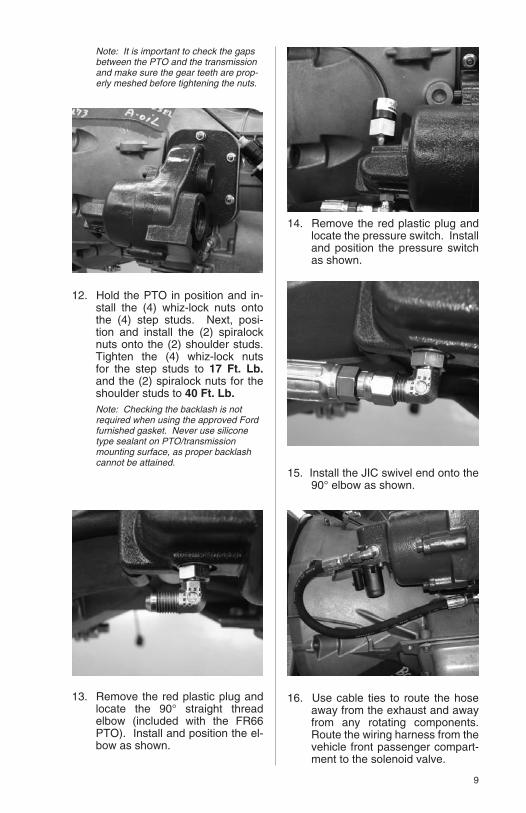
Note: It is important to check the gaps between the PTO and the transmission and make sure the gear teeth are prop-erly meshed before tightening the nuts.
12. Hold the PTO in position and in-stall the (4) whiz-lock nuts onto the (4) step studs. Next, posi-tion and install the (2) spiralock nuts onto the (2) shoulder studs. Tighten the (4) whiz-lock nuts for the step studs to 17 Ft. Lb. and the (2) spiralock nuts for the shoulder studs to 40 Ft. Lb.
Note: Checking the backlash is not required when using the approved Ford furnished gasket. Never use silicone type sealant on PTO/transmission mounting surface, as proper backlash cannot be attained.
13. Remove the red plastic plug and locate the 90° straight thread elbow (included with the FR66 PTO). Install and position the el-bow as shown.
14. Remove the red plastic plug and locate the pressure switch. Install and position the pressure switch as shown.
15. Install the JIC swivel end onto the 90° elbow as shown.
16. Use cable ties to route the hose away from the exhaust and away from any rotating components. Route the wiring harness from the vehicle front passenger compart-ment to the solenoid valve.
10
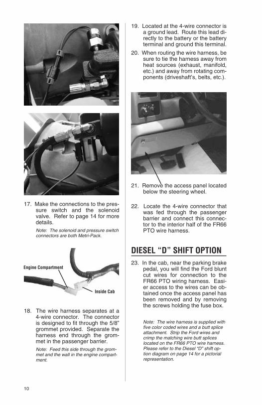
17. Make the connections to the pres-sure switch and the solenoid valve. Refer to page 14 for more details.
Note: The solenoid and pressure switch connectors are both Metri-Pack.
18. The wire harness separates at a 4-wire connector. The connector is designed to fit through the 5/8” grommet provided. Separate the harness end through the grom-met in the passenger barrier.
Note: Feed this side through the grom-met and the wall in the engine compart-ment.
19. Located at the 4-wire connector is a ground lead. Route this lead di-rectly to the battery or the battery terminal and ground this terminal.
20. When routing the wire harness, be sure to tie the harness away from heat sources (exhaust, manifold, etc.) and away from rotating com-ponents (driveshaft’s, belts, etc.).
21. Remove the access panel located below the steering wheel.
22. Locate the 4-wire connector that was fed through the passenger barrier and connect this connec-tor to the interior half of the FR66 PTO wire harness.
DIESEL “D” SHIFT OPTION23. In the cab, near the parking brake
pedal, you will find the Ford blunt cut wires for connection to the FR66 PTO wiring harness. Easi-er access to the wires can be ob-tained once the access panel has been removed and by removing the screws holding the fuse box.
Note: The wire harness is supplied with five color coded wires and a butt splice attachment. Strip the Ford wires and crimp the matching wire butt splices located on the FR66 PTO wire harness. Please refer to the Diesel “D” shift op-tion diagram on page 14 for a pictorial representation.

11
24. Connect the Muncie Blue/White wire to the Ford Blue/White wire; circuit PTO_RELAY.
25. For Stationary Operation: Re-quires Muncie FR66 special feature “X” with wire harness 34T41671. Connect the Mun-cie Yellow/Green wire to the Ford Yellow/Green wire; circuit PTORS1.
For Mobile Operation: Requires Muncie FR66 special feature “M” with wire harness 34T41896. Connect the Muncie Blue/Gray wire to the Ford Blue/Gray wire; circuit PTORS2.
26. Connect the Muncie White/Brown wire to the Ford White/Brown wire; circuit PTOREF.
27. Connect the Muncie Green wire to the Ford Green wire; circuit PTO_RPM.
28. Connect the Muncie Gray/Violet wire to the Ford Gray/Violet wire; circuit PTORTN.
29. Install the Muncie switch into the Muncie switch bracket or the ve-hicle dash. This picture above shows an area(circled) where the
Muncie switch may be installed. Note: Green wire at the top of the switch.
30. Route the wire harness to the bracket or switch location. Push the rocker switch through the face plate and into the bracket or dash. Attach the switch connector block to the switch. Be sure that the Green wire in the connector is at the top of the switch.
31. Plug relay into socket provided on the wiring harness (the relay comes standard plugged into the harness provided from Muncie).
32. Find the “Data Link Connector” lo-cated below the access panel and follow the wire behind the panel. Next, locate the Ford Violet 12V ignition switch power source and connect that wire to the Muncie Violet wire.
33. Start the truck engine (with trans-mission and the FR66 PTO in neutral) for a few seconds and lis-ten for unnatural noises. Always stay clear of rotating components.
Note: Should an unnatural noise occur, SHUT OFF the engine and place the ignition keys in your pocket. Remove the FR66 PTO and examine both the FR66 PTO and transmission for any defects. Always keep the FR66 PTO and transmission run time to a minimum.

12
34. Check transmission oil level and fill to proper level per instructions found in the vehicle owner’s man-ual. Adding a PTO will require the addition of transmission fluid. Re-install the 4x4 drive shaft if re-moved in step 3. Run engine for 5 to 10 minutes to check for leaks. Always stay clear of rotating com-ponents.
35. SHUT OFF engine and place the ignition keys in your pocket. In-spect the cap screws to make sure they are properly tightened. Mounting bolts should be checked on a regular basis for tightness.
MUNCIE PF PUMP INSTALLATION
36. The FR66 requires the use of a special hydraulic pump mount-ing which is found on the Muncie PF4-***-16QSRL pumps. This pump uses thru-bolts to mount to the FR66 PTO. This is the only pump to be used on the FR66.
Note: The 1-1/4” round keyed shaft is available on the FR66 PTO for mounting to a 4x2 chassis.
37. The PF4 series pump is supplied assembled and does not require disassembly. The proper mount-ing capscrews and flat washer are provided with the pump. It is critical that the proper mounting capscrews be used. If you did not receive capscrews, then contact Muncie Power Products, Inc. for the correct mounting hardware.
38. Before installation, place the flat washers over the shaft of the capscrew (there should be 1 or 2 washers used depending on the size of the pump being used).
39. Place the pump into the PTO output mounting by aligning the splines as well as the pilot. Align the thru-bolt mounting holes and insert the capscrews with flat washers and torque both cap-screws to 40-42 ft. lbs.
Note: The pump orientation is with the pump body offset pointing down.
40. On a 4x2 chassis, if your system contains a driveline between the FR66 PTO and another product and if are experiencing noise in your system that was not heard before, the angularity or phas-ing of your driveline may be the cause. Check the driveline angu-

13
larity and reduce the total angu-larity recommended by the chart and be sure that the PTO shaft is parallel within 1.5° to the pump shaft (or driven unit).
Note: For installations with angles in the top and side views, use this formula to compute the true joint angle (TJA): TJA= A²+B²
FR66 PTO WITH DIRECT COUPLE HYDRAULIC PUMP INSTALLATION
The Muncie PF series hydraulic pumps installed on the FR66 are of special design. This design allows for interference problems to be mini-mized.
Before bolting the pump to the FR66 PTO, place a non-seizing compound or grease on the FR66 PTO shaft and pump shaft. Muncie supplied pumps
are pre-lubricated and do not require lubrication at installation.
The use of a bracket will be neces-sary when mounting hydraulic pumps weighing over 20 lbs., exceeding 12” in length, or with tandem or multiple sections.
These pumps should be mounted using a bracket attached to the rear of the pump and to the transmission to support the pump and to inhibit move-ment in all directions.
A bracket attached to two or more trans-mission bolts is preferred. The bracket design should assure that there is no stress or force exerted on the pump or FR66 PTO shaft during the installation of the bracket.
If vertical supports are greater than 20º off of perpendicular with the trans-mission main shaft then a reinforced “Z” bracket must be used. Reinforce horizontal members to prohibit flexing at bend or weld. Attach the bracket at the pump bolt closest to the center of gravity of the pump.
Note: When making hydraulic connec-tions to the pump, it is important to route the hydraulic lines away from the front and rear vehicle drive shafts. It is impor-tant to route hydraulic lines away from exhaust manifold and pipes.
41. Complete installation by placing warning labels as indicated on borders of the decals. Placement examples are found on pages 5–6.
MaxSpeedRPM
MaxTJA“A”
3500 5°3000 5°2500 7°2000 8°1500 11°1000 12°

14
SECTION 2WIRING DIAGRAMS AND
AUXILIARY INSTRUCTIONSFR66 “D” SHIFT OPTION HARNESS
• NOTE: Installation above is for Stationary operation with Ford SEIC control. Automatic throttle advance when PTO is installed.
• For Mobile operation with wire 34T41896, connect the Muncie Blue/Gray wire to the Ford PTORS2 circuit (Blue/Gray wire).
FR66 PTO INSTALLATION WITH SPD-1001A SYSTEM PROTECTION DEVICE Requires purchase of 34T37753 and SPD-1001A (not included with the FR66 PTO)
AB
TAG
ABGreen Wire On Top
BA
GREEN - Aux PTO Engage LightYELLOW - Aux Dash Switch
Rocker Switch30T35687
For Use Without Muncie Switch
Relay
Black Battery Ground
Violet
Blue/White
Yellow/Green
White/Brown
Green
Gray/Violet
- 12Vdc Power Connection
- Output
- Input (VPWR)
- Ref. Voltage
- Input (Resistor)
- PCM Ground
Pressure Switch
Activation Solenoid
Turn Clockwise To Increase RPM
Note: The adjustment screw will increase the set RPM of the engine from the pre-set 900 RPM.
F-250/350/450/550 Diesel Engine PCM
Circuit Intent
Ford Wire TagPTO_RELAY
PTORS1
PTOREF
PTO_RPM
PTORTN
DESCRIPTION
C-11 CE326 Blue/White
C-06 CE912 Yellow/Green (Stationary)
C-55 LE434 White/Brown
C-08 CE914 Green
C-22 RE327 Gray/Violet
4-Wire Connector
FR66 Wire Harness - 34T41671 (Stationary)
Ford Wire Color: Violet
Circuit No.PCM
Pin No. Wire Color
1. Make the FR66 PTO installation as described in Steps 1-40.
2. Obtain the 4-wire connector on the FR66 PTO Harness and plug in the wire harness adapter 34T37753 (sold separately). The adapter is designed to assemble in only one direction.
3. Find the Red wire on the wire har-ness adapter and connect this wire to the SPD-1001A wire har-ness Red wire as shown in Dia-gram “A”.
4. Find the Green wire on the wire harness adapter and connect this wire to the SPD-1001A wire har-ness Blue wire as shown in Dia-gram “A”.
5 Locate Ford Blue wire (tag CTO PTOIC-1) and connect the Or-ange SPD-1001A wire.
6. Connect the Black SPD-1001A wire to a good ground at the fuse panel or battery (not to the cab).
7. Connect the White wire to an overspeed light if required, sold separately. Ground the other ter-minal of the Light.
8. Mount the SPD-1001A after mak-ing the calibration setting as de-scribed in the SPD-1001A instal-lation manual.
4 Wire Connector
FR66 PTO Wiring Harness
Blue WireRed Wire
To FR66 PTO
To Rocker Switch
4 Wire Connector
34T37753Harness Adapter
Red WireGreen Wire
SPD-1001A
DIAGRAM A
15
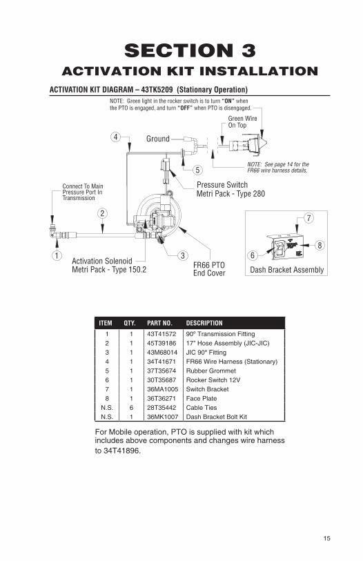
SECTION 3ACTIVATION KIT INSTALLATION
ACTIVATION KIT DIAGRAM – 43TK5209 (Stationary Operation)
Ground
Pressure SwitchMetri Pack - Type 280
Activation SolenoidMetri Pack - Type 150.2
1
2
6
4
FR66 PTOEnd Cover
Connect To Main Pressure Port InTransmission
5
NOTE: Green light in the rocker switch is to turn “ON” whenthe PTO is engaged, and turn “OFF” when PTO is disengaged.
8
7
3
Green WireOn Top
NOTE: See page 14 for theFR66 wire harness details.
Dash Bracket Assembly
ITEM QTY. PART NO. DESCRIPTION
1 1 43T41572 90º Transmission Fitting2 1 45T39186 17" Hose Assembly (JIC-JIC)3 1 43M68014 JIC 90º Fitting4 1 34T41671 FR66 Wire Harness (Stationary)5 1 37T35674 Rubber Grommet6 1 30T35687 Rocker Switch 12V7 1 36MA1005 Switch Bracket8 1 36T36271 Face Plate
N.S. 6 28T35442 Cable TiesN.S. 1 36MK1007 Dash Bracket Bolt Kit
For Mobile operation, PTO is supplied with kit which includes above components and changes wire harness to 34T41896.

16
PTO TEST PROCEDURE
1. Install the activation kit shown on the previous page.
2. With the ignition switch on (but the engine NOT running), turn on the FR66 PTO rocker switch and listen for the solenoid valve. You should be able to hear the valve snap open. If not, check your ground to make sure there is a good connection (this should be a bare metal contact to the battery ground).
3. Start the engine and engage the FR66 PTO by turning the rocker switch to the “ON” position. If the FR66 PTO fails to operate or will not develop enough torque to op-erate the equipment, check the pressure as follows.
a) Stop engine and place the ignition keys in your pocket.
b) Install a 400 PSI pressure gauge at the piston port of the FR66 PTO as shown in figure 1 below.
c) Remove the pressure switch from the FR66 end cover and place a second 400 PSI pressure gauge in the pressure switch port as shown in figure 2 below.
d) Start the engine (staying clear of any rotating components). En-gage the FR66 PTO by turning the rocker switch to the “ON” po-sition. Increase the engine speed to 1300 RPM.
e) If either gauge registers less than 130 PSI or if there is more than 50 PSI difference between the 2 gauges at any engine speed, check for obstructions in the hose or remove the solenoid and check for contamination.
f) If the gauge on the piston port registers 50 PSI or less, you may be connected to the wrong port on the transmission. Recheck the transmission information for the main pressure port location.
Port: SAE - 4
Port: SAE - 4
Port: SAE - 4

17
SECTION 4OWNER’S MANUAL
PTO SHIFTING PROCEDURE & PRECAUTIONS
PTO’s should not be engaged (turned “ON”) under heavy load and/or at en-gine speeds over 1000 RPM. If your operators are careless or negligent in this respect, you can safeguard your equipment with one or more Muncie protective systems.
CAUTION: Do NOT operate hydraulic pumps systems without the hydraulic system completely installed.
WARNING! STATIONARY OPERATION REQUIREMENTS
• NEVER GO UNDER THE VEHICLE WITH THE ENGINE RUNNING.
• Parking brake must always be set.
• Vehicle’s wheels must always be chocked.
• Transmission must always be in park.
Important: An operator must always be in the driver’s seat whenever the engine is running and the transmis-sion is in gear, in order to prevent or stop any unexpected movement of the vehicle which may cause injuries to the operator or others in the vicinity.
PTO OPERATION VEHICLE STATIONARY
1. Vehicle must be wired for Station-ary Operation.
2. The PTO drive gear is engine driven and will spin whenever the engine is turning.
3. See warning above. Set parking brake and with foot off of service brake, with the vehicle engine operating at idle, engage PTO by pushing the rocker switch to the engage position.
4. Connection of the FR66 PTO is through the Ford SEIC control. The Muncie harness will allow the throttle settings to range from 900 RPM to 3000 RPM.
The Maximum allowable operat-ing speed is an engine speed of 2000 RPM. Connection to Ford 6.7L diesel computer through the PTO activation circuit will auto-matically increase engine to a pre-set RPM as set by the PTO installer.
5. The PTO activation system is wired through the vehicle ignition. If you should leave the PTO en-gaged when you turn off the ve-hicle the PTO activation will NOT automatically turn on when the
SEIC ENABLE/DISABLE CONDITIONSVehicle Conditions to Enable SEIC (All are required)
Vehicle Conditions to Disable SEIC (Any one required) SEIC Live
Drive
Parking brake applied Parking Brake disengaged Yes No
Foot off of service brake Depressing service brake Yes No
Vehicle in PARK (automatic trans.) Vehicle taken out of park Yes No
Foot off of accelerator pedal Accelerator pedal depressed Yes No
Vehicle speed is O mph (stationary) Vehicle speed is not O mph (stationary) Yes No
Engine at a stable base idle speed Yes No
Transmission oil Temp. above 20º F Transmission Oil Temperature (TOT)Limit exceeds 240º F. Yes Yes
Engine Coolant Temp. (ECT) 120º F min. Engine Coolant Temperature Limit (ECT) Yes Yes
Catalyst Temperature Limit Yes Yes
18
enablers are met and when the engine is re-started. You will need to turn off the PTO and go through the activation process again once the engine is restarted.
NOTE: Consult your Muncie product literature or call your nearest Muncie Power Center for information on the SPD-1001A System Protection Device. The SPD-1001A is adjustable for maximum engine speed and can also prevent engagement of your PTO at unsafe engine speeds.
PTO OPERATION VEHICLE MOBILE
1. Vehicle must be wired for mobile operation.
2. With the vehicle engine operating at idle and the selector in Park, engage the PTO by pushing the rocker switch to the “engage” po-sition.
3. Release the parking brake, shift the transmission into a drive or reverse selection.
4. The Torqshift® transmission is designed to allow PTO operation in all gears including over-drive.
PTO MAINTENANCE
The Power Take-Off, being an integral part of the transmission, should be serviced at the same intervals as the transmission. Changing transmission fluid should follow the interval recom-mended by the vehicle manufacturer for severe service. Transmission oil level is important. Checking for PTO leaks and checking the transmission oil level should be done on a regular basis.
The Power Take-Off is also part of a system. The PTO system may include the activation control parts, a driveshaft, or hydraulic pump. This PTO system requires periodic checks and service. Typically the interval for maintenance checks of the PTO system depends on the application of the system. Every time the chassis is lubricated or a mechanic is under the vehicle the PTO system should be checked and/or serviced. For severe duty PTO system applications, it is recommended that the system be
checked for service every 100 hours of use (this guideline can be adjusted based on past service history once you have it established).
Service should include checking and lubricating direct mount pump shaft connections. PTO gears can be checked for wear by removing the PTO. If pitting, galling, cracking, or deformation of the gears or splines has occurred, then the PTO needs to be rebuilt or replaced. Within the first week of use, recheck installation of PTO. Check for leaks and loose mounting hardware.
At regular maintenance intervals; check adjustments and lubricate moving parts, tighten and repair connections and mounting hardware. Pumps that are mounted directly to the PTO output require the application of an anti-seize or a high temperature and/or high pressure grease (Mun-cie PTOs are initially supplied with required grease). The purpose of this grease is to help make PTO easier to service and to reduce the effects of fretting corrosion on the mating PTO and pump shafts. PTO applications under severe duty cycles and/or high torque requirements may require servicing this shaft connection by periodically re-greasing shafts. Fret-ting corrosion cannot be stopped by applying grease; the grease is only a deterrent.
PTO TORQUE & HORSEPOWER RATINGS
Intermittent service refers to an On-Off operation under load. If maxi-mum horsepower and/or torque is used for an extended period of time, (5 minutes or more), it is consid-ered “Continuous Service” and the horsepower rating of the PTO should be reduced by multiplying the value below by 0.70.
PTO Series FR66Speed Ratio 09Intermittent HP @1000 RPM* 38 22.8Intermittent KW @1000 RPM 28 17Torque Ft. Lbs.* 200 120Torque N-M 271 163Maximum PTO Speed 2500
Stationary Mobile
* Torque & HP limitations are mandated by Ford to limit transmission loading.
19
FR66 - PTO TROUBLESHOOTING GUIDE
PROBLEM POSSIBLE CAUSE REMEDY PREVENTION
PTO DOES NOT ENGAGE
FORD required wiring installation not followed.
Inspect and reconnect PTO activation wire connection on the PTO harness.
Refer to wiring diagram found in Section 2.
Contaminated hydraulic activa-tion lines.
Remove contami-nants from piston area.
Change transmis-sion oil filter.
Transmission Hy-draulic Pressure not high enough.
Hydraulic line connected to the wrong port.
Review instal-lation diagrams found in section 2.
Burned or extremely worn clutch pack.
Replace worn components.
Use proper shift procedures.
Rocker switch incorrectly con-nected.
Remove con-nection at rocker switch, check pins and re-install per instructions on Step 30.
Make sure green wire in connector is at top when installed.
PTO DOES NOT DISENGAGE
Faulty hydraulic solenoid valve.
Repair or replace. Sometime a result of contamination or dirty valve.
Burned or extremely worn clutch pack.
Repair or replace components.
Follow proper engagement procedures. See section 3.
PTO ENGAGES LOW/NO OUTPUT SPEED OR PUMP FLOW
FORD required wiring installation not followed.
Inspect and reconnect PTO activation wire connection on the PTO harness.
Refer to wiring diagram found in section 2.

POWER TAKE-OFF WARRANTY
The Muncie Power Take-Off is warranted to be free of defects in material or workmanship and to meet Muncie’s standard written specifications at the time of sale. Muncie’s obligation and liability under this warranty is expressly limited to repairing or replacing, at Muncie’s option, within one year after date of original installation any defective part or parts or any product not meeting the specifications.
THIS WARRANTY IS IN LIEU OF ALL OTHER WARRANTIES, EXPRESSED OR IMPLIED. MUNCIE MAKES NO WARRANTY OF MERCHANTABIL-ITY OR OF FITNESS FOR ANY PARTICULAR PURPOSE. MUNCIE’S OBLIGATION UNDER THIS WARRANTY SHALL NOT INCLUDE ANY TRANSPORTATION CHARGES OR COSTS OF INSTALLATION OR ANY LIABILITY FOR DIRECT, INDIRECT, SPECIAL, INCIDENTAL, OR CONSE-QUENTIAL DAMAGES OR DELAY. THE REMEDIES SET FORTH HEREIN ARE EXCLUSIVE, AND MUNCIE’S LIABILITY WITH RESPECT TO ANY CONTRACT OR SALE OR ANYTHING DONE IN CONNECTION THERE-WITH, WHETHER IN CONTRACT, IN TORT, UNDER ANY WARRANTY, OR OTHERWISE, SHALL NOT, EXCEPT AS EXPRESSLY PROVIDED HEREIN, EXCEED THE PRICE OF THE PRODUCT OR PART ON WHICH SUCH LIABILITY IS BASED.
If requested by Muncie, products or parts for which a warranty claim is made are to be returned transportation prepaid to a Muncie Service Center. Any installation or use not in accordance with catalogue or package instructions, other improper use, operation beyond capacity, substitution of parts not ap-proved by Muncie, use with equipment other than the equipment on which the Power Take-Off is first installed, or alteration or repair made to the Power Take-Off other than at a Muncie Service Center shall void this warranty. No employee or representative of Muncie is authorized to change this warranty in any way or to grant any other warranty.
Muncie Power Products, Inc. Member of the Interpump Hydraulics GroupGeneral Offices and Distribution Center • P.O. Box 548 • Muncie, IN 47308-0548 • (765) 284-7721FAX (765) 284-6991 • E-mail [email protected] • Web site http://www.munciepower.comDrive Products, Exclusive Agents for Canada, ISO Certified by an Accredited Registrar
IN10-01 Printed in the U.S.A.