Embed Size (px)
Citation preview
Installation Instructions
H/H SE Handlebar Mount Fairing
We have tried to make these instructions as explicit as possible; however these
instructions are supplied as a suggested guideline only. Due to the many various models
of motorcycles that they can be mounted on there is no possible way to describe
completely detailed instructions that will cover every installation. The Installer is
assumed to be competent to properly complete the subsequent installation.
In some case the L rods or other shaped mounting rods may need to be bent or formed to
proper alignment by the installer in order to properly align the brackets and the fairing
mounting points.
Harper Enterprises Inc and Hannigan Fairing Company assume no responsibility for the
mounting of this fairing or the use of the supplied brackets unless the fairing is installed
at either Harper Enterprises Inc. or Hannigan Fairing Company retail locations.,
***********************************************************************
H/H SE fairing bracket kit.
1. 4 Standoffs
2. 2 Fork Clamps
3. 2 Handlebar clamps
4. 4 L Rods
5. 8 6mm set screws
6. 4 6x16 6mm Pan Head screws
7. 6 Rubber Washers
8. 6 Fender washers
9. 8 Rubber caps
See Instruction sheet before mounting
Prior to beginning the installation of the H/H SE fairing please read the directions
thoroughly. If you are not comfortable with doing the installation yourself please consult
a qualified mechanic at your local dealer.
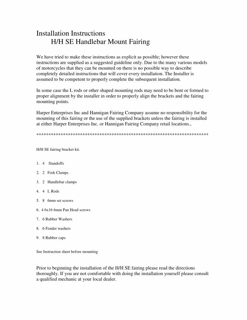
There are two sets of two piece clamps included in this kit. The larger set fit onto the
main fork legs directly under and up against the lower triple clamp with the caps facing
forward. The smaller set fits the handlebars and normally mounts with the caps facing the
rider at an angle. This may not always be possible. Install both sets but lightly snug the
Allen head screws just to hold the clamps in place. (DO NOT TIGHTEN)
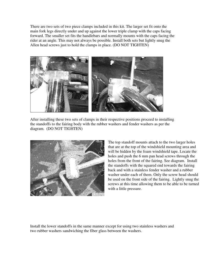
After installing these two sets of clamps in their respective positions proceed to installing
the standoffs to the fairing body with the rubber washers and fender washers as per the
diagram. (DO NOT TIGHTEN)
Install the lower standoffs in the same manner except for using two stainless washers and
two rubber washers sandwiching the fiber glass between the washers.
The top standoff mounts attach to the two larger holes
that are at the top of the windshield mounting area and
will be hidden by the foam windshield tape. Locate the
holes and push the 6 mm pan head screws through the
holes from the front of the fairing. See diagram. Install
the standoffs with the squared end towards the fairing
back and with a stainless fender washer and a rubber
washer under each of them. Only the screw head should
be used on the front side of the fairing. Lightly snug the
screws at this time allowing them to be able to be turned
with a little pressure.
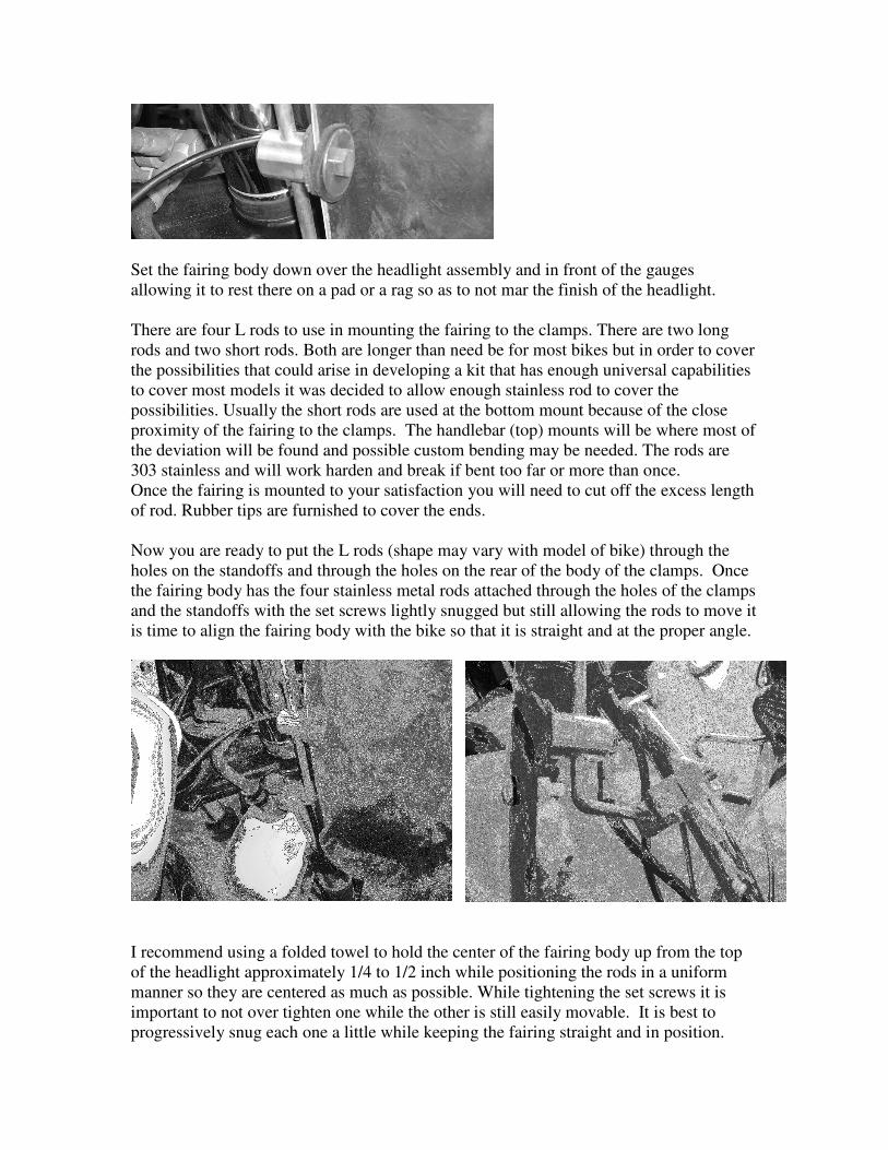
Set the fairing body down over the headlight assembly and in front of the gauges
allowing it to rest there on a pad or a rag so as to not mar the finish of the headlight.
There are four L rods to use in mounting the fairing to the clamps. There are two long
rods and two short rods. Both are longer than need be for most bikes but in order to cover
the possibilities that could arise in developing a kit that has enough universal capabilities
to cover most models it was decided to allow enough stainless rod to cover the
possibilities. Usually the short rods are used at the bottom mount because of the close
proximity of the fairing to the clamps. The handlebar (top) mounts will be where most of
the deviation will be found and possible custom bending may be needed. The rods are
303 stainless and will work harden and break if bent too far or more than once.
Once the fairing is mounted to your satisfaction you will need to cut off the excess length
of rod. Rubber tips are furnished to cover the ends.
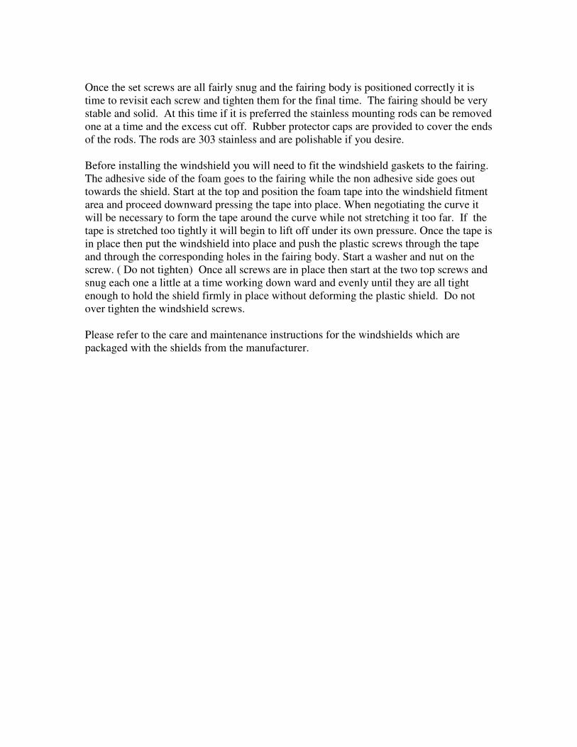
Now you are ready to put the L rods (shape may vary with model of bike) through the
holes on the standoffs and through the holes on the rear of the body of the clamps. Once
the fairing body has the four stainless metal rods attached through the holes of the clamps
and the standoffs with the set screws lightly snugged but still allowing the rods to move it
is time to align the fairing body with the bike so that it is straight and at the proper angle.
I recommend using a folded towel to hold the center of the fairing body up from the top
of the headlight approximately 1/4 to 1/2 inch while positioning the rods in a uniform
manner so they are centered as much as possible. While tightening the set screws it is
important to not over tighten one while the other is still easily movable. It is best to
progressively snug each one a little while keeping the fairing straight and in position.
Once the set screws are all fairly snug and the fairing body is positioned correctly it is
time to revisit each screw and tighten them for the final time. The fairing should be very
stable and solid. At this time if it is preferred the stainless mounting rods can be removed
one at a time and the excess cut off. Rubber protector caps are provided to cover the ends
of the rods. The rods are 303 stainless and are polishable if you desire.
Before installing the windshield you will need to fit the windshield gaskets to the fairing.
The adhesive side of the foam goes to the fairing while the non adhesive side goes out
towards the shield. Start at the top and position the foam tape into the windshield fitment
area and proceed downward pressing the tape into place. When negotiating the curve it
will be necessary to form the tape around the curve while not stretching it too far. If the
tape is stretched too tightly it will begin to lift off under its own pressure. Once the tape is
in place then put the windshield into place and push the plastic screws through the tape
and through the corresponding holes in the fairing body. Start a washer and nut on the
screw. ( Do not tighten) Once all screws are in place then start at the two top screws and
snug each one a little at a time working down ward and evenly until they are all tight
enough to hold the shield firmly in place without deforming the plastic shield. Do not
over tighten the windshield screws.
Please refer to the care and maintenance instructions for the windshields which are
packaged with the shields from the manufacturer.