Embed Size (px)
Citation preview

. : 7*»r
7 O » O- f\ irt 11 fi> -Io \ £ 0 I) 1 @ iI
NASA CR-112250March ' 1973
FLIGHT SERVICE EVALUATION
OF PRD-49/EPOXY COMPOSITE PANELS
IN V7IDE-BODIED COMMERCIAL TRANSPORT AIRCRAFT
Final Report
John H. Wooley, Dale R. Paschal and Eugene R. Crilly
CASE F I L ECOPY
Prepared under Contract No. NASI-11621
For
Langley Research Center
National Aeronautics and Space Administration
Hanpton, Virginia 23365
Lockheed-California Company
Burbank, California
A Division of Lockheed Aircraft Corporation
https://ntrs.nasa.gov/search.jsp?R=19730011291 2018-07-03T19:26:13+00:00Z

e-
••. . - / . • . , ' . • '. V-; -"? . , !•' -:* ..'>•":>?•-' . ; ~ :

FOREWORD
This technical report was prepared by the Lockheed-California Company
•under Contract No. HAS1-11621, "Flight Service Evaluation of PKD-lfe
Composite Panels in Wide Bodied Commercial Transport Aircraft". It summarizes
the work performed during the period of May through November 1972 which includes
testing, machining development, fabrication, manufacturing cost studies and
installation of PED- 9 fairing panels. The remainder of the program involves
a five year evaluation of the panels in commercial airline service.
This program has been administered by the Langley Research Center
National Aeronautics and Space Administration with Mr. Benson Dexter of the
Materials Division being the Project Engineer,
Individuals who have made contributions at the Lockheed-California
Company and Heath Tecna Corp., the fabricator of the panels, are as follows:
John H. Wooley
Dale R. Paschal
Eugene R. Crilly
Lloyd ¥. Nelson
Donald J. Mackey
Owen M. Klasen
J. S. Southv?orth
John VanHamersveld
I.L» Bertrand
Glen H. Smith
I.L. Smith
T. Johnson
Donald Colclough
Program Leader
Commercial Engineering, L-1011Project Coordinator
Science and Engineering Coordinator
Commercial Engineering StructuresDivision Engineer
Commercial Engineering, StressDepartment Engineer
Structures Laboratory Engineer
Structures Engineer, Sr.
Science and Engineering Staff Engineer
Manufacturing Research Engineer
Manufacturing Research Engineer
L-1011 Assembly Department Manager
L-1011 Assembly Supervisor
Heath Tecna Manufacturing Engineering
11

Section
TABLE OF CONTENTS
Page
SUMMARY 1
1.0 INTRODUCTION 3
2.0 MATERIALS 7
3.0 STRUCTURAL ANALYSIS 12
4.0 . PART FABRICATION l6
5.0 MACHINING DEVELOPMENT 20
5.1 Trimming and Cutting .20
5.2 Drilling and Countersinking 22
6.0 PANEL INSTALLATION 2h
7.0 MANUFACTURING COST STUDY 27
8.0 SPECIAL TEST SPECIMENS 30
9.0 FLIGHT SERVICE EVALUATION 31
10.0 RESULTS AND RECOMMENDATIONS . 32
APPENDIX A - STRESS ANALYSIS DATA FOR PRD- 9 PANELS 3^
List of Symbols 35
A-l. Wing-to-Body Fairing Panel Analysis 37
A-2. Wing-to-Body Fairing Fillet Analysis ij-1
A-3. Center Engine Fairing Panel hh
APPENDIX B - MACHINING DEVELOPMENT 50
B-l. Prepreg Cutting Procedures 51
B-2. Laminate Trimming and Machining 5"!
B-3. Drilling and Countersinking 58
REFERENCES 9
ill
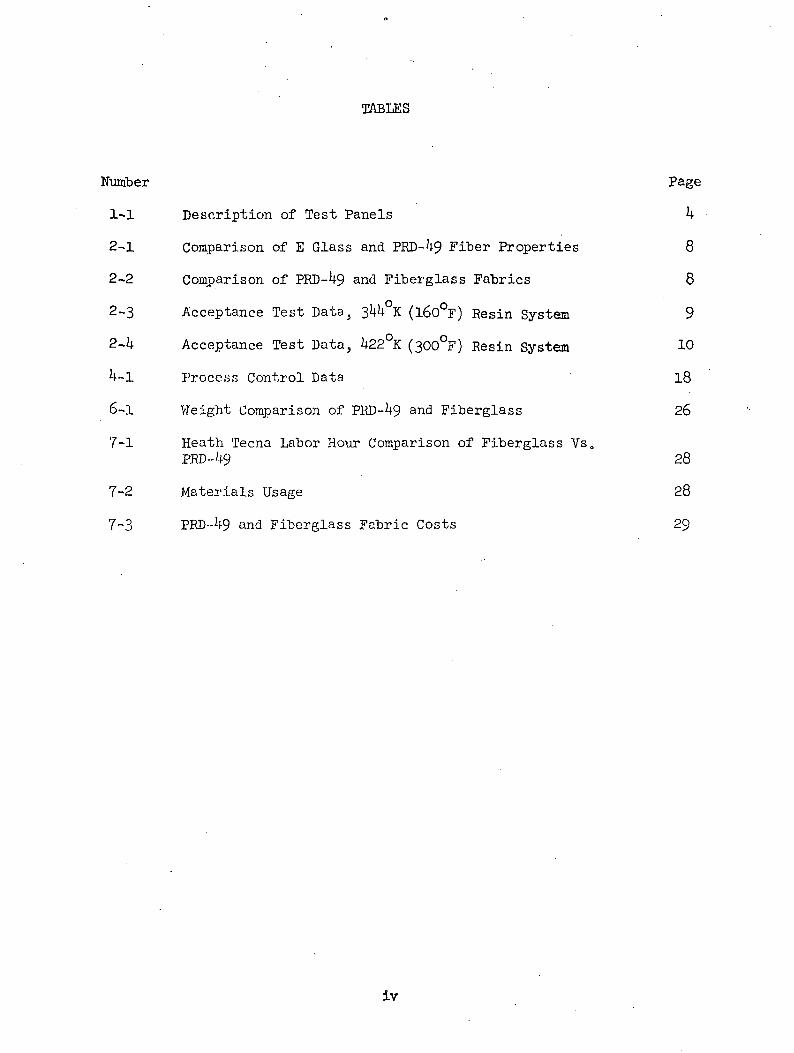
TABLES
Number Page
1-1 Description of Test Panels k
2-1 Comparison of E Glass and PRD-49 Fiber Properties 8
2-2 Comparison of PRD-49 and Fiberglass Fabrics 8
2-3 Acceptance Test Data, 344°K (l60°F) Resin System 9
2-4 Acceptance Test Data, 422°K (300°F) Resin System 10
4-1 Process Control Data 18
6-1 Weight Comparison of PRD-49 and Fiberglass 26
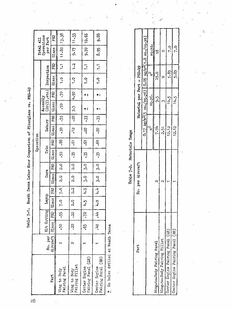
7-1 Heath Tecna Labor Hour Comparison of Fiberglass Vs0PRD--49 28
7-2 Materials Usage 28
7-3 PRD--49 and Fiberglass Fabric Costs 29
iv

FIGURES
Number
1-1 PRD-1*9 Fairings . | 5
3-1 Wing-to-Body Fairing Panel in Fixture for ExternalPressurization Test j 13
3-2 Wing-to-Body Fairing Panel in Fixture for InternalPressurization Test - . I 13
3-3 Wing-to-Body Fairing Panel in Fixture Showing 'Compression Skin Failure After External 'Pressurization Test ll*
3-1* Panel Removed from Fixture Showing Compression SkinFailure After External Pressurization Test ll*
5-1 Frayed Fibers on PRD-1*9 Laminate Using StandardTools for Fiberglass 21
5-2 Drilled and Countersunk Hole in PRD-1*9 LaminateUsing Standard Tools for Fiberglass 21
5-3 Drilled Hole in PRD-1*9 Laminate Using NewlyDeveloped Drill ?3
5-1* Drilled and Countersunk Hole in PRD-1*9 LaminateUsing Newly Developed Drill and Countersijik Tool 23
6-1 Installation of the Wing-to-Body Fairing Panel toLocate Holes and Trim Line Along Bottom Edge 25
6-2 Wing-to-Body Fillet Panel Installed on Aircraft 25
6-3 Center Engine Fairing Panel Installed on Air CanadaAircraft 26
A-l Wing-to-Body Panel Illustration 37
A-2 Wing to Body Fillet Panel Illustration 1*1
A-3 Center Engine Fairing Panel Illustration 1*1*
A-l* Center Engine Fairing Panel Section 1*5
B-l Carbide Saw 18 Teeth 53
B-2 Carbide Saw 18 Teeth 5!*
B-3 Carbide Saw 8 Teeth 55
B-l* Comparison of Cuts by Nibbler and StandardFiberglass Router 57
B-5 Black and Decker Porto-Shear Used to Trim Wing-to-Body Fairing Panel During Installation 59

Mo. | Page
B-6 Trimming Wing-to-Body Fairing Panel with Porto-Shear 59
B-7 Special Drill Point for PBD-49 Laminates 6l
B-8 Stepped Double Margin Drill 61
B-9 Countersink A \.1& ran (O.l8? inch) Dia. \ 62
B-10 Countersink B U.?6 mm (O.l8? inch) Dia. \ 6h
Yi
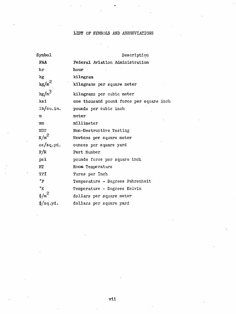
LIST OP SYMBOIS AND ABBREVIATIONS
Symbol Description
FAA Federal Aviation Administration
hr hour
kg kilogram
kg/m kilograms per square metero
kg/m kilograms per cubic meter
ksi one thousand pound force per square inch
Ib/cu.in. pounds per cubic inch
m meter
mm millimeter
NDT Non-Destructive Testing
N/m Ne'wtons per square meter
oz/sq.yd. ounces per square yard
P/N Part Number
psi pounds force per square inch
RT Room Temperature
TPI Turns per Inch
°F Temperature - Degrees Fahrenheit
°K Temperature - Degrees Kelvino
$/m dollars per square meter
$/sq.yd. dollars per square yard
vii

SUMMARY
Three L-1011 fairing panel configurations were selected as test parts to
compare the fabrication, costs and service performance characteristics of
PKD- 9 and fiberglass. These parts are currently fiberglass reinforced
structure and the purpose of this program is to evaluate the results of
direct substitution of PRD- 9 fabric for the fiberglass. Three ship sets of
these panels have been fabricated for a five year flight service evaluation
on three L-1011 commercial airlines operating in widely diverse route
structures.
The same epoxy resin systems were used for the PKD-U9 fabric to elim-
inate matrix variables and maintain the same processing procedures. The
simple replacement of fiberglass with PRD- 9 in these panels (six per ship
set) saved 7.35 kg (16.2 pounds) per aircraft or 26.6 percent of the weight
of the fiberglass panels.
The standard tools and machining techniques used for fiberglass parts-
are unacceptable for cutting, trimming, and drilling the tougher PRD- 9
fibers. Therefore, a machining development study was undertaken to provide
the necessary new tools and machining techniques. After incorporating these
new developments in the fabrication and installation of the panels, a manu-
facturing cost study revealed that the labor hours were only increased by
about 12.5 percent. This results in an added cost of $ 33.00 per kg ($15.00
per pound) of weight saved. Material cost increases amounted to $ 113.00 per
kg ($ 51-50 per pound) of weight saved for the large wing-to-body fairing
panel, $ 123.00 per kg ($ 56.00 per pound) for the wing-to-body fillet and
$ 303.00 per kg ($ 137.50 per pound) for the center engine fairing.

"Page missing from available version"

1.0 INTRODUCTION
The objective of this program is to provide a means of comparing manuf-
acturing techniques, costs and long time commercial airline service performance
of BuPonts1 new, lightweight PRD-U9 fabric with the conventional fiberglass
fabric.
Three fiberglass fairing panel configurations on the Lockheed L-1011 were
selected as test articles for this evaluation. These panels are described in
Table 1-1 and are shown in Figure 1-1.
The L-1011 provides an excellent means of evaluating the service per-
formance of PKD- 9 fabric since the various commercial airline customers log
up to 3000 flight hours per aircraft each year in widely diverse environments.
A set of each of the above mentioned panels (left and right hand sides) will
be flight tested for five years on a TWA aircraft having transcontinental
flights, an Air Canada aircraft which is exposed to the cold northern climate
and an Eastern Air Lines aircraft which operates in the eastern seaboard
environment. An estimated 270,000 hours of flight service will be logged by
these eighteen panels over the 5-year service evaluation period.
Additional environmental exposure data will be obtained from 200 flexural
specimens, 200 compression specimens and 200 interlaminar shear specimens,
which have been fabricated with two resin systems, for testing by NASA Langley
over the five year period.
Prior to obtaining FAA and airline approval to install, this new material
on the aircraft, several steps were taken to assure that the structural in-
tegrity and reliability of the parts were not jeopardized. Material and
Process Specification requirements were established, physical and mechanical
properties were determined and two of the large wing-to-body fairing panels
were static tested to failure.
Prior to the start of this program, it was recognized that one of the

COH
1PH
•Pco
§•H-Pft•HftOCOID
11p CD•9 -HX ^a o>
CO
a3<v£j
^^«
X CD0 0H COft <M
I J £$
CO
cj*r\o
*ss
o•H•PO
e-pCO
oo
oCD
^>EH
<D
g
-p_(
o3PH
-P
aPH
"STWO
d oJ- voco —
s--pH-H
«
OJ 0<0 W
ir\ ONoj t^-
OJ
v —S.I?O -H
• t—H VD
M IJrN
A1.Sir\
« OH VD
iCO
^ dCD oO
co cdPH -P
0ra Ko -do !>o psW o
SiCTNO^^ i — irH r— 1
1 |O"s CT\ON ONITN lf\ir\ ir\H HUA ITNH H
H
o 3PQ PH
-p rj1 -HbO ^H
•H 'cd^P,
x-^
Dw oo VD^j~ "• — *CO
•p*H
•OJ D1
^ CO
O\ rHH «
• OJO »—-
•Hg
_? 00CO CO
X* X
OJ '
"-•
•H
f^
PiL^
' ^0) CO
"S !C P
(-1 0)
•d §*.,_] jC^H coO
CO tN]
sscr\ oO HrH H
1 1CO COOJ OJco roLTN LTN
LfN UAH H
-P<U
•fe" l4O -H
0 bO•P d
1 -HUO ?H
•H 'cd
**
^^ow o
0 OOJ COOJJ"
^j"S-l
4
CT*OJ CO
CO •• t-
•H —
-H
M ojCO t~-
H X
x ag ^
VD Ot- CO
1,£*co
t -H
1 — 1 EH
Q)
PH Q)-H
,£5 CO
O -H0 X>3 OQ) fnC! ftO ft
II
ON C--OJ H•H H
1 i
ON col/NVO
CO -4-
LTN LfN
CD i — 1d CD
bO 3G PH
bOh G(U -H
^t^ g I
0) a}O P>H
n
^^3CO
CDa•H
G3
H
GO
GO•H-P
gU
M
3IoCO

I " • ' • " • Y"'-- #^'?lf^vijv7^V.|''--v «^* / *-
p| • :\?'S& -;'v {^r'.ff -• •••-:'!^^.--^-^M^^^^MA:^m^^^ ^^PWW'®*'-/'*fr-^y*j$3&&£':•-"' ^'''•>:vvl» '; f:^^4^» :' '. '• •;,&•*»- ®si.'."W-'- •>' f& v&k ••'•>•-•#& ''.-..Ir -if--: •„ , .**„¥vJp^'^< r-^« K ••,- 2p>J '.' V- .-.''f S f K
ffiA.S^'itt-f0*^!!!!
'ings' -^'-^^i-.

major problems associated with the use of PRD-U9 fabric was the trimming,
drilling and countersinking of cured parts. Hence, in addition to fabrication
of the parts for flight service evaluation, studies were performed to develop
satisfactory methods of accomplishing the above mentioned machining operations.
Cost differences between fabrication of PRD-49 and fiberglass parts were also
identified. The data thus accumulated should help to point out any differences
between the two materials and provide answers to some of the unknowns
associated with the use of PKD-^9.

2.0 MATERIALS
The low density of PRD-1*9 makes this fiber very attractive for new com-
posite aircraft applications as well as a replacement for fiberglass on
existing aircraft parts. The tough, abrasion resistant characteristics of
the PKD- 9 fiber permit weaving into fabrics having properties and handling
characteristics very similar to comparable styles of fiberglass, yet the
fiber density of PRD- 9 is 3 percent lower. A 30-35 percent weight savings
can be realized by direct substitution in laminates and 18 - 28 percent can
be saved in sandwich structure depending on the type and quantity of core
used. For this program two PKD-M? fabric styles were used. One was a 0.17P
kg/m (5 oz./sq. yd), 0.25 mm (0.010 inch) thick weave similar to 181 style
fiberglass 8 harness satin 0.30 kg/m (8.8oz/sq. ydK and the other was a?
0.06 kg/m (1.8 oz/sq. yd), 0.13 mm (0.005 inch) thick plain weave materialP
comparable to 0.11 kg/m (3.2 oz/sq. yd), 0.13 mm (0.005 inch) thick fiber-
glass. A comparison of the fiber and fabric characteristics is given in
Tables 2-1 and 2-2, respectively. The PRD-1*9 specification requirements used
for controlling the material are indicated in the Tables.
In considering resin systems for use in this program, Hexcel's F-155
epoxy resin was selected for the 3iA°K (160 F) service environment of the wing-to-
body honeycomb fairing panels and solid laminate fillets, and their F-l6l
epoxy resin system was used for the 1*22°K (300°P) service of the center engine
honeycomb fairing panels. Previous tests with other resin systems in com-
bination with PRD- 9 had produced comparable results, however, the Hexcel
system was selected since it is the resin currently used on the L-1011 fiber-
glass fairings. This permitted a direct comparison of PED-U9 with fiberglass
by eliminating many other variables inherent in the use of different resin
systems. It also permitted the use of the same tooling, bagging techniques
and cure cycles during fabrication of the fairing panels.
The impregnated material was ordered to the requirements of a Lockheed-
California Company Material Specification. Results of the acceptance testing
are provided in Tables2-3 and 2-h along with the specification requirements. Add-
itional property data obtained from the process control specimens is shown in

CO
e
H
ON
COCO
gCO
oo
OJ
f-t
O.Q•H >3fe -P.
•HH cdCO Cld Q>
•fH f~las
0)
•H CO
•dlp* o•iH irfo^J
-f-3
fn bO<1> d
fi Sr^-, i ^
CO
« COd H
•H >rHH Wo c
CO
•H
COF""j ~r
fw S•H 530 *r*l
fe°
i~i<u•H^_iCO-p
CO •& a
~~\ iHbO
jj
CO oo \r-| ,£>
i — |
^ COt— IfN
-=1- O
H ^
(.VI ''g -H
-~^ cos P)
ON VD0 0H H
CO OCO CMH 11 VD
ON 0O HH
X
CO-3- HCM —H
CMM
^ —•iHON w
O .Mi-l
0X O
COITNt-
OJ
COH
H "^OJ VDH J-O• O
O ^
HH
ON M-j-1 <U
CO ^~N
s •"b^ ^HM •
jj
CO Oo *-\
r~l
^ oON ON-=i- ooj v_!-
s~^OJ .H
S CO
VDON O
O H
^wif\
-& *• O
OJ H
OJ
^ON""1 ^O COH W
X OIfN
CO COH
CM
COH
1 '0'ON VDO CO
• O0 ^s
ww03HO
—
p^
**
COosiCOCO
3sHP-4
5>
IPH
cS
gCO
o
OJ
OJ
s
.p
11•H O
S £j
03w0)
r H
O
•H
dg•H
O£sj
• I—
t> 5H
COg
S £|3
l~~l|— i
08 I
PM r*"j!j
&
CO
aQ_
15
CH aO C
r^ SH CC
?H ^co o;
P
0•H
,aa3PH
;p
•dd*r~)g
|j
CO
t>5
CO
CJ•HJ-l
rC5aj
•d•r-{£-1
0)•p
^
*-TO
+ 1
CO
*OJ
+ 1CO
•*
t,0)•H Hd Pntt) EHP
ONO •COCO
WCO0) PiR -HC, I *>
CD flJW CO
ca
g wS i — 1
tH•j* sOJ O• H
o —
d coS i—^
•H.ON $E{OJOJ. ON
O
OJ
^S *
tfi/NOJ—
co •'dt — LfNl-*
^ 1 CTO w
1 Lf\s"N'
H t— NVD «0
• V f
O
oj "d*~v^^ •
X w1 \ON NVD 0H
« IfNO
*OJ
+ !
CO
*OJ
+ 1_H-
CO
1Is<U EHQ
ONITN •ONH
*jj•aH
rt ' *S M
Ht- -HOJ HH
• IfNO v-'
g ^S CO
HOJ .HC5 ^r — I
* :+0 -^
OJ
-\bp
* "~"-3" J ^VD ON >sO • •• H o1
O i coI VQ *~*»*»^
VDVO NITN « OOH
• *•* f
O
oj 1\ w•SHr
oHVD coo •
• Ho —
HH
ON HJ-
1 CU
s gPH EH
CO
ovo
OJ
rH
oLTNH
COCOco dtj i^t
03 fl3W co
CO
& CO3 |_J
•H~N S
OJ O• H
O »— '
g CO5 p^
•iH
OJOJ
• o\0-—
OJ C
> ^
LfN
^_IfN
OJ
H"
O
*
-p0o
tf-t>5o
ri s — x
s wH
, — |• LfN
&*-*S W
HOJ -H~) rf
H£} V '
3
IPIfN -~N
ON vU± CO •ro od°70^O HoI 1 coH O^
OJ COO* N ^
O
HCOH
rH * *dH CO >M
O* 1 D*1 COi-l CO \ 'ONVD NO • O
• OJ
OOJH
COcoojH
^
CO
•s
Ia>
•s•HO<UftCO
•da>0)
o
8

TABLE 2-3 ACCEPTANCE TEST DATA
(160°F) Resin System
Property
Wet Resin Content. Percent "by Weight
VolatilesPercent by Weight
Gel TimeSeconds.
Tensile UltimateDry R.T.p
N/m(psi)
Tensile Modulus. Dry R.T.
N/m(psi)
CompressiveUltimateWet R.T.?
N/m(psi)
SandwichFlatwiseTensile R.T.?
N/m(psi)
0.1? kg/m£
Spec.Requirement
42-48
2 Max.
180-660
Q
4. 137x10(60,000)
30.34xlQ9
(4.4x10 )
1.379x10(20,000)
f-*2.068x10(300)
(5 oz/sq.yd. )Fabric
Actual
1*8.047.1
1.11.3 ...
. . . 2 8 5
4. 295x10? (62 ,300)4.240xlOn(6l,500)4.213xlOn(6l,100)4.151xlOn(60,200)U.U82xlO (65,000)
U. 276x10 (62,100).
29.65x10 ( .3x10 )30.3 x10 .4x10?)31.72x10 ( .6x10?)31.03x10 (4.5x10.)32.41x10 (4.7x10 )
3i.03xio9(4.5xio6)
n
1.551xlOo(22,500)1.420xlOn(20,600)1.358x100(19,700)1.482xlOo(21,500)1.420x10 (20,600)
1.446x10 (21,000)
s •**-2. 068x10? (300)2. 172x10? (315)1.965x10? (285)2. 068x10? (300)2.034x10 (295)
2.061x10 (299)
0.061 kg/
Spec.Requirement
Vf-53
2 Max.
180-660
3.792x10(55,000)
26.2xlO§(3.8x!0b)
o1.379x10(20,000)
(•*2.068x10°(300)
m (1.8 oz/sq.yd. )Fabric
Actual
51.6
1.0
300
3.875xlO?(56,200)4.102xlOn(59,500)4.137xlOo(6o,000)3.826x10 (55,500)3. 936x10° (57, 100)
3.975x!08(57,6oo)
25.51x10 (3.7x10?)26.89x10 (3-9x10?)26.89x10 (3.9x10.)26.20x10 (3.8x10.)26.89x10 (3.8x10 )26. 48xlo9( 3.8x10°)
0
1.317x10 (19,000)1.538x100(22,300)1.420xlOo(20,600)i.434xiOo(20,8oo)1.462x10 (21,200)
i.434xio8(20,8oo)
, **1.965xlo?(285)2.068x10 (300)2. 034x10? (295)2. 137x10? (310)2.206x10 (320)
2.082x10 (302)
* Core failure below this value acceptable
** All specimens failed in core

TABU: 2-4 ACCEPTANCE TEST DATA°K (300°F) Resin System
Property
Wet Resin ContentPercent by Weight
Volatile sPercent by Weight
Gel TimeSeconds
Tensile UltimateDry, R. T.?
N/m(psi)
Tensile Modulus.Dry R.T.p
N/m(psi)
CompressiveUltimateWet R. T.p
N/m(psi)
SandwichFlatwise
Tensile R.T.?N/m
(psi)
0.17 kg/m2
Spec.Requirement
42-48
5 Max.
60-1*20
n4. 137x10(60,000)
30.34xlQ9(4.4x10 )
1.379xl08
(20,000)
2.068x10(300)
(5 oz/sq.yd. )
Fabric
Actual
1*6.8
.99
180
Q4.17lxlOft(6o,500)4.295xlOn(62,300)4.557xloft(66,loo)U. 233x10°,' 6l, Uoo)U. 351x10 (63,100)4. 321x10 (62,600)
33.09xio9(4.8xio£)29.65xio (4.3xiou))31. 03x10 (4. 5x10°)31.72x10 ( .6x10 )31. 72x10 (U. 5x10 )3l.03xio9(U.5xlo6)
ol.UOOxlO«(20,300)l.U75xloS(2l,Uoo)1.365x100(19,800)1.558x10 (22,600)1.5 x10 (22, 00)
ij
l.U68xlo (21,300
2.137x10 (310) '2.179x10 (316)2.220xlOfi(322)2.206x10 (320)2.068x10 (300)
2.162x10 (313)
0.061 kg/m
Spec.Requirement
7-53
5 Max.
60-lf20
3.792xl08
(55,000)
26 . 20xl09
(3.8x10°)
Q
1.379x10(20,000)
2.068x10(300)
2(1.8 oz/sq.yd. )
Fabric
Actual
52.1
1.1
180
3. 937x10? (57, 100)3.8o6xiOg(55,200)3.868x10 (56,100)U.020xlOg(58,300)3.875x10 (56,200)3.902x10 (56,600)
26.20x10 (3.8x10 )25.51x10 (3.7x10⁵)26.89x10 (3.9x10°)27.58xioJ(if.Oxio5)26.20x10 (3.8x10 )
26.if8xl09(3.8xlo6)
Q
1.538x100(22,300)I.if62xl0o(21,200)1.420xlOo(20,600)1.317x100(19,100)1. 69x10 (21,300)1.441x10 (20,900)
6 **2.034x10 (295)2.137x10 (310)2. 193x10°. (318)2. 206x10 (3 20)2.227x10 (323)
2.162x10 (313)
Core failure below this value acceptable
** All specimens failed in core
10

Table U-l in the Fabrication Section.
The core used in the honeycomb panels was 3• 17 mm (V^ inch) cell size,
1*8.1 kg/m3(3 lb/ft3) density Nomei^Hexcel1 s HRH-10) .
R) Du Pont Registered Trademark
11

3.0 STRUCTURAL ANALYSIS
In order to prove the feasibility of using PRD-il9 in L-10U wing-to-body
fairing panels, the largest of the panels, P/N 1515599? "was fabricated and
statically tested in the fixture shown in Figures 3-1 and- 3-2. This panel has
a width of 1.52 meters (60 inches) and a length of about 1.7 meters (67 inches).
It is contoured to airplane loft lines. In the original test panel, a ply for
ply substitution for fiberglass was made so that the outer skin consisted of
two plies of 0.13 mm (0.005 inch) thick PPD-l+9/epoxy [.06 kg /m2 (l.8 oz/sq.yd)]
in lieu of 120 style fiberglass and one ply of 0.25*4- mm (0.010 inch) PRD-^9
[.17 kg /m (5.0 oz./sq. yd)]in lieu of l8l style fiberglass. The inner skin
was made up of three plies of the lighter weight PRD-^9 fabric. The edge band
was built up for attachment purposes to approximately 2.5*4- mm (0.100 inch).n p
This panel was subjected to a static internal pressure test of 8.27 x 10° N/m
(1.2 psi) and then tested to failure with external pressure. Design ultimate3 2for external pressure is l6;55 x 10 N/m (2.k psi). In this initial external
pressurization test, a crack was noted propagating from a fastener hole at
approximately mid-span in the 1.7 meter (67 inch) direction of the panel ato 2
about design ultimate of 16.55 x ICr N/m (2.h psi) but the panel continued too 2
carry load until the pressurization bladder failed at about 20.3^- x 10 N/m/T r~)
(2.95 psi). The calculated skin stress was 125.U6 x 10 N/m (16,600 psi) when
analyzed by the methods given in Appendix A. Lockheed's preliminary design£> P
allowable in compression for this material is 121.01 x 10 N/m (16,100 psi)
when an 0.8 multiplying factor is used to compensate for the thin material
0.508 mm (0.020 inch). Most test data is obtained on laminates 3.175 mm
(0.125 inch) thick.
Since the original panel was still carrying load when the pressurization
bladder failed, it was decided to test a new panel with three plies of the
light weight fabric on the outer face in an effort to determine if a moreo 2
efficient structure could be utilized. This panel failed at 1 .13 x 10 N/m
(2.05 psi) demonstrating that the thinner face sheet, 0.381 mm (0.015), was not
structurally acceptable. The failure mode was a compression buckle on the
outer (compression) skin in the flat portion of the panel as shown in Figures
3-3 and- 3-^« The fiber stress on this face at failure was calculated to be
12

Figure 3-1 Wing-to-Body Fairing Panel in Fixturefor External Pressurization Test
Figure 3-2 Wing-to-Body Fairing Panel in Fixturefor Internal Pressurization Test
13

-»-,V' .*Bi.- jj rfe--- ••jtsgjv ss
»., ..~-.;,iAfei*&
Figure 3-3 Wing-to-Body Fairing Panel in FixtureShowing Compression Skin Failure AfterExternal Pressurization Test.
Figure 3-^ Panel Removed From Fixture ShovingCompression Skin Failure AfterExternal Pressurization Test.

£ p106.18 x 10 newtons/meter (15,1*00 psi). For the .38 ram (.015 inch) thick
/* pPRD-U9/epoxy laminate, the preliminary allowable was 10 .5 x 10 N/m
(15,100 psi). As a result of this failure it was deemed necessary to make
all of the flight test PKD- 9 wing-to-"body fairing panels per the original
construction of two plies of the lightweight and one ply of the heavier
weight fabric. This was a ply for ply substitution for fiberglass. This
construction would provide a margin of safety of +0.1 in compression with6 2a calculated fiber stress of 97.9 x 10 newtons/meter (14,200 psi).
The structural analysis of the three basic parts, the'honeycomb wing-
to-body fairing panel, the solid laminate wing-to-body fairing fillet and
the honeycomb center engine support fairing are given in Appendix A. These
analyses have been approved by FAA Designated Engineering Representatives.

h.O PART FABRICATION
Eight honeycomb wing-to-body fairing panels, (two of these panels were
for test), six wing-to-body solid laminate fillets, and six honeycomb sand-
wich center engine support fairing panels were fabricated at Heath Tecna
Corp., Kent, Washington. They also fabricate the basic fiberglass fairings
used on the L-1011. Both the wing-to-body honeycomb panels and fillets used
PRD- 9 impregnated with Hexcel's F-155, 39U°K (250°F) cure, 3 °K (l60°F)
service epoxy, whereas, the center engine fairing panels used Hexcel's F-l6l,
ll-500K (350°F) cure, U22°K (300°F) service epoxy. All honeycomb was 3-175 mmO O —
(0.125 inch) cell size, U8.1 kg/m (3 Ib/ft ) nominal density NomexQycore.
In the case of the center engine fairing panels, a layer of compatible ad-
hesive was placed between the core and prepreg to insure structural integrity
of the parts. The F-155 system had adequate filleting characteristics to
provide a good structural bond between the core and fairing material for the
K (160 F) service wing-to-body honeycomb panels.
The process requirements established for each step in the fabrication
operation are presented in the following discussion. It should be noted that
all of the steps are identical for fiberglass and PRD-U9-
When cutting the PKD- 9 prepreg, it was found that only about half the
number of plies could be cut at once when compared to fiberglass because of
the greater toughness of the fibers.
Prior to lay-up, the tools are coated with a water soluble release agent
and then a 0.10 mm (O.OOU inch) to 0.18 mm (0.00? inch) thick layer of
aluminum is sprayed on the tool. The metal spray is then sealed with an
appropriate epoxy resin compatible with the ultimate cure temperature of the
part. This resin sealer is then gelled at 320°K (115 F) for one hour to
facilitate subsequent lay-up. Lay-up of the appropriate number of plies is
then done in accordance with the Engineering drawing. Handling of all pre-
impregnated fabric during cutting and lay-up phases is done under controlled
atmospheric conditions with the temperature maintained between 292 K (65 F)
QR) Du Pont Registered Trademark
16

and 305 K (90°F) and the relative humidity between 20 percent and 65 percent.
Following lay-up of the .inner skin of honeycomb panels, a ply of .025 D™
(.001 inch) Tedlarnyis applied to the surface of this skin to serve as a
moisture barrier. During the lay-up operations, it was determined that one
additional step may be required during the manufacture of parts using PRD-1+9/
epoxy prepreg. With fiberglass prepreg which is somewhat transparent, it is
possible to mark a doubler or filler ply as a means of locating the next ply
to be laid down. The PRD-1+9 is not sufficiently clear to permit marking
during lay-up, which necessitates a physical measurement to locate each
doubler. It would appear, however, that a simple template could be designed
which would locate each ply in relation to the core bevel, or the trim line
of the part.
No deviation from the specification for bagging and curing was required
to produce panels in which PRD- 9 was substituted for fiberglass.
Cure of the 3^ K (l6o F) service epoxy system is accomplished in an auto-o " ^ 2
clave using a pressure of 2^1 x 10 + 3. 5 x 10° N/m (35 + 5 psi). The temp-
erature is raised from ambient at a rate of .6 K (l F) to 3-^ K (6 F) per
minute and then held at 39U°K (2|?00F) to 1|08°K (275°F) for one hour minimum.
The part is' then cooled down to 3^ K (160 F) maximum under pressure at which
time it can be removed from the autoclave. For the 1+22 K (300 F) service parts,
the same cure pressure and temperature rise rate is used as for parts cured at
391+°K (250°F). The cure temperature of 50 + 11°K (350°F + 20°F) is maintained
for 2 hours minimum and the part cooled under pressure until it reaches
(160 F) maximum at which time it is removed from the autoclave. Process control
coupons are fabricated with each part using the same materials and simultaneously
cured with the part. Test results from the process control specimens for the
PRD-U9 test panels are provided in Table U-l. No process controls in addition
to those used for fabrication of fiberglass parts were deemed necessary.
Inspection of all parts consists of a visual examination which, in the
R) Du Pont Registered Trademark
17

4-1. PROCESS CONTROL DATA
Part No.
1515599-109
1515599-HO
1545238-109
1545238-110
1538592-129
151 685-117
P R O P E R T Y
Wet Compression(RT)
Spec.Regmt.
131xl06
N/m'J
(19,000PS!)
Actual
N/m2 .
1 1 xiof1 9 xlO?
139 xlO
155 xlO^1 6 xlO?1 5 xlO
137 xlO139 xlo£138 xlO
15 xlO.138 xio5lUO xlO
15? xlO?138 xlO^Ih2 xlO
135 Jcio5137 xlO^lUl xlO
. psi
20, 00. 21,60020,200
22,50021,20021,000
19,90020,20020,000
22,UOO20,10020,300
22,00020,00020.600
19,60019,90020,500
Sandwich FlatwiseTensile (RT)
CTJPP
Reqmt.
1.83X10⁶
N/m
(265 psi)
Actual
N/m2
2.03x102.1 x102.10x10
2.03x10². 00xlo£2.1 x10
2.1!+xl062.17x10?2.07x10
1.97x10;?2.00xlo52.21x10
2.21xlOr2.2Uxlo52.1 x10
2.03x102.19x10?2.10x10
psi*
295. 310
305
295290310
310315300
285290320
320325310
295318305
* Core Failure
18

case of PKD- 9 panels, is..less revealing than for fiberglass panels because
of its greater opacity. Therefore, greater emphasis must be placed on KDT
procedures. It was found that a tapping procedure used for WDT of fiberglass
•parts worked equally well on previously fabricated PKD- 9 panels. Therefore,
it was used for checking panels made for this program. This tapping procedure
used a standard aluminum tapper which is bullet shaped at one end and is
approximately 12.7mm x 37.7mm (1/2 inch x 1-1/2 inch). The tapper is attached
to a handle by a heavy wire. The parts are tapped in a 0.15m (6 inch) grid
pattern starting at one corner and working to the opposite corner.
No problems were encountered in the fabrication of any of the parts except
for the last left hand center engine fairing panel which partly adhered to the
tool. Possible repair procedures were considered but it was decided to scrap
the part and use it for further evaluation of machining procedures.
Another part was fabricated and no difficulties were encountered. It should
be noted that the.same situation has been occasionally encountered in the
fabrication of 1450 K (350 F) cure fiberglass parts. There are several
possible causes of this, any one of which might present itself on either glass
or PRD-i4-9 parts: namely, (a) insufficient thickness of release agent applied
to the tool prior to flame spraying: (b) positioning of the flame spray nozzle
too close to the tool, resulting in burn-through of the parting agent; (c) an
excessive coating of flame spray coupled with one or both of (a) and (b); or
(d) improper application of the gel coat over the flame spray.
In any event, this was an isolated case and should not be cause for
concern, except to alert those involved with fabrication to exercise additional
care in the preparation of tools involving 50°K (350 F) cure temperatures.
Trimming, drilling and countersinking operations for the cured panels are
discussed in the Machining Development section of this report.
19

5.0 MACHINING DEVELOPMENT
Previous experience with PED- 9 in both epoxy and phenolic matrices indicated
that this material is very difficult to cut and drill. When the standard fiber-
glass cutters and drills were used on PRD-U9 laminates, tool life was drastically
reduced and machined surfaces were badly frayed. In an effort to resolve the
problem, a portion of this program was devoted to the development of new machining
tools and techniques. The results of this effort are described in detail in
Appendix B.
5.1 Trimming and Cutting
Fiberglass reinforced laminates normally are cut and trimmed with diamond
coated saws and diamond coated router bits. However, with PKD- 9/epoxy laminates
these tools rapidly loaded up or became coated v/ith resin and fiber particles.
The 2.5 - mm (0.10 inch) thick edge laminates on the sandwich panels were overheated
and the loose fibers smouldered and occasionally burst into flame. In overheated
areas, some delamination was also noted. Figure 5-1 illustrates the fraying that
was experienced.
As a result of the development effort at Heath Tecna, special multi-tooth
carbide tipped saw blades were designed such that the cutting action would draw
the edge fibers downward into the larainat-e. These saw blades produced the
cleanest cut (least amount of fabric fraying), however, the cutting edges dulled
quite rapidly when compared to the tool life experienced with cutting fiberglass.
Heath Tecna used a two step operation for cutting the PKD- 9/epoxy fairing
panels. The initial cut was made with the carbide tipped blades described above
and a finish cut to dimension was made with a diamond shaped cut carbide router bit
which trims an additional 0.75 - 1.0 mm (0.030-0.01*0 inch) beyond the initial
cut. The routing operation removes the majority of the frayed fibers prior to
the final finish deburring (sanding) operation. The two step cut and trim
operation adds about 75 percent more labor hours to the cutting time required
for fiberglass.
20

:5|fn1 ;'f|j"'5lfif f" '.%
i C'.Yv l- ~';v~}*s$lt''. '.•'•'
••*••.'..• ••;•.*-'" • ?*
Figure 5—1 Frayed Fibers on PRD-'49 Laminate Using
Standard Tools for Fiberglass.
•'• ; ' ; "5 ' I - . " ' - '!
Figure 5-20 Drilled and Countersunk Hole in PRD- 9
Laminate Using Standard Tools for
Fiberglass.
21

5.2 Drilling and Countersinking
As with the cutting 'tools, the standard drills and .controlled depth counter-
sink tools presently used for fiberglass laminates were not acceptable for PRD- 9/
epoxy laminates. These tools produced badly frayed fastener holes and irregular
countersinks as shown in Figure 5-2«
Development of an efficient drill point requires a configuration which draws
the fibers inward toward the center and cuts them. This approach was also taken
in the development of the countersink design. It was also determined that a
back-up plate of relatively hard wood or micarta was required to produce a clean
hoi60 Figures 5-3 and 5-^ ars samples of holes and countersinks produced by the
tools and techniques developed in this program.
The use of back-up blocks will require some additional labor, however, the
actual drilling and countersinking operation would be about the same for PRD- 9
and fiberglass. Tool life factors could not be determined since long term
continuous drilling was not performed.
22

"Ha' lv^vH^*"U,&'&'«nf-'-i l\"^vr&&«v HV- v »T -n
^*h:^V.i:tr,iMM';:-\tv:'<r
Tool
23

6:0 PfflEL INSTALLATION' ' - 1
1
During the period of November 6 - 17, 1972, the PRD-^9 epoxy! fairing
panels were installed on two aircraft - Air Canada's airplane, Serial 502,
and Eastern Air Line's airplane, Serial 31^« The final set of pariels were
installed on TWA's airplane, Serial 007 in February 1973- Prior to in-I
stallation of the flight test panels, the regular fiberglass panels were
fitted, trimmed, installed on the aircraft, then removed, and deposited in
a bonded area. These production fiberglass panels are to be delivered with
the aircraft to the airline customers and will later be used as replacements
or spares. Eastern Air Line's airplane was delivered January 3, 1973 j Air
Canada's airplane was delivered February 12, 1973> and TWA's airplane was
delivered in March, 1973.
The large wing-to-body fairing sandwich panels were drilled and trimmed
net on three sides by Heath Tecna. Each panel was subsequently positioned on
the specified aircraft and the hole location and trim line were marked on the
unfinished side. (See Figure 6-1). Trimming and drilling of this one side was
then completed on the final assembly line. The Porto-Shear described in the
Machining Development section (Appendix B) was used for trimming the panels net.
and minor hand sanding was done to remove the few frayed fibers that remained.
The wing-to-body fillet panels and center engine fairing panels were
trimmed net by Heath Tecna but the attach holes were drilled on final assembly
after locating on the specified aircraft. A wing-to-body fillet and a center
engine fairing panel are shown installed on the aircraft in Figures 6-2 and 6-3,
respectively.
Weights of all of the fiberglass and PKD-J*9 fairing panels were determined
after final trimming and drilling. A comparison of the weights, provided in
Table 6-1, demonstrates that 7-35-kg (16.2 pounds) per aircraft (26.6 percent)
can be saved by using PRD-^-9/ epoxy on these six panels.

p-tK . '.<="•jStFPv? .;• ,-T'"--T FTI- .3*v -•< s -5F7- ' .* • !--'••>if "--v ^ rV- p' '•.-•- T--*''?' &_x>:*
Figure 6-1 Installation of the Wing-to-Body FairingPanel to Locate Holes and Trijn LineAlong Bottom Edge
; r--> ^••.{n^aat^; - " lusaajuaaSijijjiiaaEW' ^^ fgjAj iis^y^ fjpES^^
• €» .; '-' ; '- ' ^^vi ^^S^^- '*^T-, 'ly ^v"ri':' • •"• "•••',• '- ^f;'K~f^ttVt^'jf-'':ffff'!',:f''^.H. K,•-•'•.. !Vt*,'»<Br-j.-~i',»jb.E,iaw-4sr/-W«j. f
Figure 6-2 Wing-to-Body Fillet Panel Installed onAircraft

CENTERENGINEFAIRING
Figure 6-3 Center Engine Fairing Panel Installed onAir Canada Aircraft.
TABLE 6-1. Weight Comparison of PRD-^9 and Fiberglass
Part
Wing-to-fuselage fairing panel
Wing-to- fuselage fillet panel
Center engine fairing panel
Total
FiberglassWeight
kg Ibs.
9.3 20.6
1.3 2.8
3.2 7.0
13.8 30.
PHDWeight
kg Ibs-.
7.0 15.5
.9 1.92.2 U.9
10.1 22.3
Weight SavingsPer Part
kg Ibs.
2.3 5.1.h 0.91.0 2.1
3.7 8.1
' Per A/C
kg Ibs.
U.6 10.2
.8 1.8
2.0 U.2
7.U 16.2
Weight Savings - 26.6 percent
26

..I
7.0 MANUFACTURING COST STUDY
A requirement of the PRD-lf9 panel fabrication at Heath Tecnauwas to record
the labor hours for each step in the operation. A comparison of the PRD-lf9 labor!
hour requirements and the hours for the equivalent fiberglass partis is given in
Table 7-1. I
Using the figures generated at Heath Tecna, it can be shown that an
additional 9-37 hours were required to fabricate one ship set (6 panels)wiihPRD-H9.
On a percentage basis this is equivalent to a 15«5 percent increase in labor hours
for the PKD—*f9 panels. Converting these increases into dollars involves assumptions
concerning labor rates, burden, scrap rate, general and administrative (G & A)
costs and profit. For purposes of this report, the following figures have been
used.
Shop Labor $5.50/hr
Inspection Labor $6.00/hr
Burden 1^0 percent of labor costs
Scrap Rate 5 percent
G & A 16 percent
Profit 11 percent
In addition, special tools costing $300 for the three ship sets of parts were
required and thus must be added to the overall costs.
The weight saving realized on one ship set of parts was l6.2 pounds or 26.6
percent. Therefore, it can be shown that the above cost elements amounted to
an added $37»5O per kilogram ($17.00 per pound) of weight saved.
As discussed in the Machining Development Section (Appendix B), subsequent
work at Lockheed demonstrated that trimming time could be reduced with the use of
a Black and Decker Porto-Shear. It is estimated that the Porto-Shear could reduce
PRD- 9 trimming time from the .2 hours suggested by Heath Tecna to 3-30 hours per
shipset. Since the quality of the cut edge is improved with the Porto-Shear, the
deburring tirae should be about equal to that required for fiberglass. This would
reduce the added labor hours from 9-37 for one ship set to 7-55 hours for an
increase of 12.5. percent above the fiberglass panels. Using the same labor rates
27
Tab
le 7
-1.
Hea
th T
ecna
Lab
or H
our
Com
pari
son
of F
iber
gla
ss vs
. PR
D-if
9
mrfSta -H <a.•%*•ds n
• P O O,0 0, ftH O
Op
erat
ion
Insp
ecti
on
Ass
embl
y(D
rin
,etc
)D
ebur
r
gt-<
EH
n3
&£>j
bflc•H
S
C^-Pa
aa,
COtoa
C
aPL,
tntoor5
§P-,toenrt5
§»<to§3
EM
tnto<a3§(X,
w3
iitatoa!
d
i.(0ina)
C3
fc -PO V(ftg• o
0 f-4
*3
ta!
PL,
^ro
§•
* —
V•
O*
•x —
or~«
oU"\•
ITNU\
*
Oro.
COCO
•
0LPv•
O*
CM
O
CM
M3•
r~
o•t-
LTNLT\.
Ou>.
co
>i <B
•H gCQ Pn
O bo-P C
•HbO Pi
5 "Si2= fc,
roro•
r-.
ON
C\J*
o«
r~
OON.
ITN.
ro
OCM.
CMT-
•
\o•
1/Nro
•
O
CM
O
CM
CM.
CM
0•CM
81 •«
oCM
CM
4J(D
^rH13 ^O -H
PQ [t,
O M-P C
•HW> f<
-S'SJrs fe
voVO
oT—
O
r—•a\
T—•
O•
* 1
*l
rnro•
OCM•
T—VO•
LTVPO•
O*
no
O•ro •
ON• .-H-
ir\•
-HT
CMr—•
ITNVO
*
-
Cen
ter
Eng
ine
Fai
rin
g P
anel
(L
H)
COCO
«ON
£*
00
T—•
T—
O•
*l
*l
roro
«
3•
T—MD•
Lf\ro
•
0•
o->
O•on
-3-•-H-
O
•
-3-
•
5•
r-
Cen
ter
Eng
ine
Fai
rin
g P
anel
(R
H)
a)ao0
EH
5cti0>
sT3CJHi-l
TJT3
M0)
•clA
g
*l
ro-p
1
o\
A(1
-g&OH
»ft
f— 1
Co
•d-pcdS
cto
x^
oOC
E
b
voC
0
9£>cto!
C
ITN
C\T
b
r—*0
-P
1oh
p0>ft
o
•g(t)
P-4
T3S
cfin
CME
•O
tf0]
CMg
CO
oir\H
u~\ON
J-ON
r-
CM
H
iPKW}C
tf•aT3O
PQ
i
1to
5^
o
o
f*->
^_LTN
CM
CM
-P(D
rHr-H•H
boa
•Ha]
•
4?omAtM
13
O
[^_
CO
LTN
IA
JT—
CM
O
CM
1
rHID
§
toC
2a)^^toc
Wi
(D
^3
ai0
0•^»
CO
ITN
LTN
^1
CM
^
1
O
§bDC
g
0)
5bfl
W
f^
Q)4-'a0)u
28

and factors as above, the added costs for fabricating PKD- parts is $33.00 per
kilogram ($15<>00 per pound) of weight saved.
A material cost analysis was made to determine the added costs of using
Since there was a direct substitution of PRD-1f9 for fiberglass, the same amount of
prepreg was used for both fabrics. The actual usage for each part is given in
Table 7-2. The material costs used in this analysis are shown in Table 7-3- A
10 percent material burden, 5 percent scrap, 16 percent G & A,, and 11 percent
profit was added to the cost of each fabric.
It was found that the material cost per pound of weight saved is a function
of the relative amounts of 0.170 kg/m2 (5.0 oz./sq.yd.) and 0.061 kg/m2 (1.8 oz/sq.yd.)
materials used. In the case of the wing-to-body fairing panel and wing-to-body
fairing fillet the material costs were $113-00 and $123.00 per kg ($51-50 and
$56.00 per pound) of weight saved, respectively, whereas the center engine fairing
panel calculates to be $303.00 per kg ($137«50 per pound) of weight saved. This
points out that the use of PR&-49 in lieu of fiberglass might be best accomplished,
at least in the initial phases, on a selective basis where it would be most cost
effective for the weight saved. In the case of the center engine fairing panel, the
high cost per pound of weight saved may be attributed to the shape of the part
and the high usage of the 0.17 kg/™2 (5-° oz./yd2) fabric relative to the usage
of the lighter weight fabric. The triangular shape of the part introduces a
high trim loss in the prepreg, hence, more material is wasted than for a rectangular
part of the same overall dimensions. The high usage of heavy weight fabric may
be attributed to the large periphery relative to area of the part. For economy
in lay-up time the heavy weight material is used to build up edge thickness.
Also, the cut-out area is built up as a solid laminate during lay-up and then the hole
cut after cure of the part. See Figure 6-3 for cut-out area,
Table 7-3. PRD- 9 and Fiberglass Fabric Costs
Material ThicknessInch
0.25^ mm
(.010 inch)
0.127 i™
(.005 inch)
PI$/m2 '
$16.15
$7.18
iD-to$/sq.yd.
$13.50
$ 6.00
Fiberglass$/m^
$2o15
$2.79
$/sq.yd.
$1.88
$2.33

8.0 SPECIAL TEST SPECIMENS
Also included in the program was the fabrication "by Heath Teona of 600
test specimens - 100 short beam interlaminar shear coupons, 100 fl'exure test
coupons, and 100 Celanese type compression specimens using the 0.17 kg/ra
(5 oz./sq.yd) PRD- 9 impregnated with the F-155 resin and a like number using
the same fabric impregnated i th the F-161 system. These specimen^ will be
tested by the NASA Langley Research Center after a variety of environmental
exposures.
30

9.0 FLIGHT SERVICE EVALUATION
Lockheed has established a program, in cooperation with affected airlines,
to gather a five year flight service history on the PRD-U9 fairings. After all
fairings have been installed on the selected commercial aircraft, annual flight
service inspections will be conducted during the routine inspections by the air-
lines. Reports on the inspections will include sufficient detail to explain
comprehensively how the inspections were conducted and results obtained. A
schedule of reporting has been established as follows:
Air Canada's aircraft will be inspected yearly in accordance with
standard procedures, and a copy of the report will be forwarded to
Lockheed.
Eastern Air Lines will keep Lockheed informed as to the location of
the aircraft involved at the time of the required inspection. If
possible, a member of Lockheed's Maintainability Department will be
on location for the inspection. If not, a copy of EAL's inspection
report will be submitted through Lockheed's Product Support organi-
zation.
The TransWorld Airlines aircraft involved will be inspected at the
Los Angeles International Airport by Lockheed Maintainability and
Project personnel and the cognizant TWA personnel.
Lockheed will prepare a yearly report on the findings of «n three air-
lines and make the normal report distribution which is stipulated by NASA. A
final report on the total program will be issued at the conclusion of the five-
year flight service evaluation. It has been determined that PRD- 9 panels may
be repaired in accordance with the L-1011 Maintenance Manual, Section 51-50-05,
06, and 07, using standard fiberglass repair kits. Accordingly, this infor-
mation has been entered in the Maintenance Manuals for ACA., EAL, and TWA. Any
panels which are damaged beyond repair will be replaced with the spare fiberglass
panels. The damaged panels will subsequently be evaluated by Lockheed and NASA.
31

10.0 EESULTS AND RECOMMENDATIONS
In the initial phase of this program considerable information was obtained
in comparing the fabrication characteristics of PRD- 9 fabric with fiberglass.
Exposing the test panels to commercial airline service for the next five years
will indicate the service performance that can be expected from this new fiber.
Prior to receiving FAA approval to fly the PRD- 9 panels commercially,
material and process control specifications had to be established and the
structural analysis had to be confirmed by static tests. The preliminary
allowables established for this material and the structural analysis of the
panel match the static test results very well. However, more mechanical
property data is needed for designing thin skin structure and much more infor-
mation on environmental effects is required. The six hundred test specimens
fabricated in this program for subsequent testing by NASA after environmental
exposure and the flight service of eighteen fairing panels will provide much
of the needed information.
A portion of this program was devoted to the development of new tools and
machining techniques for PKD- 9 laminates since the standard fiberglass tools
were not acceptable. In cutting the prepreg it was found that only half, as
many plies of PKD- 9 could be cut at one time and the cutting blades dulled
much faster. In cutting and drilling the PRD-H9 laminates, tools were designed
such that the cutting action would draw the edge fibers toward the center of
the work. The selected tools successfully cut and drilled the material, however,
in many cases the tool life was drastically reduced when compared to the per-
formance of fiberglass tools.
Late in the development program, Lockheed was successful in producing
trimming tools for PRD- 9 laminates which were almost as efficient as those used
on fiberglass. The tool life was increased but the extent could not be measured
due to limited usage. More work is required to identify more specifically the
life and efficiency of the tools developed in this program.
The lay-up and curing of the PKD-U9 parts was no different than the fiberglass
since the same resin systems were used. The only problem with PKD-U9 epoxy is that
it is more opaque than fiberglass, hence it was difficult to locate successive
layers dirring lay-xip and aboxvb 10 percent more inspection time was required.
32

After final trimming and drilling in final assembly, the weights of each
of the PRD- and fiberglass panels were measured. A ship set of six PRD-lf9
panels resulted in a 7. kg (16.2 pound) weight savings or a 2606 percent
reduction of the fiberglass weight.
A manufacturing cost study was conducted on each step in the fabrication
process to analyse the cost differential between the labor hours required to produce
parts from the two fabrics. After employing the new tooling developments from the
program, 7 *55 additional hours were needed to produce a ship set of PRD- 9 test
panels.. This amounts to a 12. 5 percent labor increase or $33*00 per kg ($15.00
per pound) of weight saved. It is believed that time can be reduced even further
with experience and additional tool development.
The material cost study showed quite a difference in the added costs for
PRD-49 in the various panelso PRD- 9 material costs added $113.00 per kg
$51»50 per pound) of weight saved in the wing-to-body fairing panel, $123.00 per kg
($56.00 per pound) in the wing-to-body fillet, and $303.00 per kg ($13?.50 per pound)
in the center engine fairing panel. This can be attributed to the various mixes of
.251! mm (.010 inch) and 0.127 m™ (0.005 inch) thick fabrics in the three parts and
the excessive amount of prepreg trim that is lost on the center engine panel.
Tne cost differential between the 0.25 mm (0.010 inch) thick fiberglass and
PRD- 9 is $"lU.OO per m ($11.62 per sq. yd.) whereas the differential between
0.127 mm (0.005 inch) thick material is $ .39 per m2 ($3.67 per sq<, yd.) Therefore,
the parts with the highest quantity of 0.127 mm (0.005 inch) thick fabric had the
lower cost increases<,
33

APPENDIX A
STRESS ANALYSIS DATA FOR FAA APPROVALOF PRD-49 PANELS

LIST OF SYMBOLS AND ABBREVIATIONS*
BL = buttock line (horizontal distance from vertical centerlineplane of aircraft)
C = constant
E = modulus of elasticity
F.S. = fuselage statioa(horizontal distance from vertical distanceplane perpendicular to aircraft centerline)
G = modulus of rigidity (shear modulus) of core
I = moment of inertia
M = bending moment
MS = margin of safety
V = dimensionless parameter incorporating sandwich bending andshear rigidities
2 where D = bending stiffnessV TT JJ
,2 u - transverse shear stiffnessU
(See analyses for particular forms of this equation.)
W.L. = water line (vertical distance from horizontal distance planeof aircraft)
a = panel length
b = panel or beam width
d = sandwich thickness = tn + t0 + t1 d c
h = overall thickness of beam
L = span of beam
p = pressure
t = thickness
y •- average distance from neutral axis to exterior surface
"X*Special symbols used in this Appendix.. Other symbols defined on page vii
35

LIST OF SYMBOLS AMD ABBREVIATIONS (Cont'd)
a = stress
U = Poisson's ratio
2X = 1 - \JL
Subscripts
1 = outer facing
2 = inner facing
a = property in direction of a
b = property in direction of b
c = compression when used with E, cr and y
c = core when used with G and t
f = flexure
t = tension
u = ultimate (failing) value
36

A-10 JWing-to-Body Fairing Panel Analysis
The -w ing-to-body fairing panel is a honeycomb sandwich.
fabric was substituted on a ply for ply basis for fiberglass in the panel
skins with core thickness and density also the same. The panel is approx-
imately 1.52 x 1.70 meters (60 x 67 inches) and contoured to airplane loft
lines. It is a secondary fairing provided to maintain an aerodynamic shape
for the lower fuselage forward of the main landing gear compartment. It
transfers air loads to a peripheral structure. A sketch of the panel is
shown below. . . - •
yc =10.03 mm(0.395 in.)
Neutral Axis— — -«- —
Honeycomb HRH-10
Inner Face - tg = .38 mm (.015 -in.)
; t = 22.h mm (.1" c
J'in.)
Outer Face.- t = .51 mm (.020 in.)
Figure A-l. Wing-to-Body Panel Illustration
37

This analysis is provided to substantiate the strength of the wing-to-
body fairing panels with PRD- 9 facings. Buttock line (B.L.) traces
through this panel are approximately straight but fuselage station (F.S.)
traces show a curvature varying from about 3.8l m (150 in.) radius near
buttock line 2.5 to about 1.27 m (50 in.) near buttock line Il6. (See
Figure A-l.) The critical portion of the panel is the inboard, nearly
flat section which is analyzed conservatively as a flat panel using the
method outlined in Section 6, Reference 1. The internal loads are 8027 x• 3 p ^ 2
10 N/m (102 psi) whereas the external loads are 16.55 x 10 N/m (2,k
psi) so only external loads are considered. This flat portion of the panel
is 1.52 m (60 inches) in the "a" direction and 0.889 m (35 inches) in the
"b" direction.
Allowables used for PRD-^9 laminates are as follows:
,GU.
= 386.9 x 10 N/m2 (56.11 x 10³ psi)
Et = 25.9 x 10⁹ .N/m2 (3.76 x 10 psi)
- CT = 138.8 x 10 N/m2 (20.13 x 10³ psi)
E, = 2U.9 x 109 N/m2 (3.61 x 10 psi)L*
U = 0.2 .
The Nomex honeycomb core used in these panels was 3»l8 x 10 " meter
(1/8 inch) cell size and i|-8.1 kg/m (3.0 Ib/ft ) density, and G = 37.9 x6 2 c
10 N/m (5500 psi) in the longitudinal direction.
Panel parameters are as follows: (See Figure A-l)
i,I = 0.508 x 10"3 meter (0.020 inch)
t2 = 0.381 x 10"3 meter (0.015 inch)
t = 22.i4 x 10'-1 meter (0.88 inch)
a = 1.52 meters (60 inches)
b - 0.89 metera (35 inches)
X = (1 -u2)

I = 2.8? x 10~° meter /meter of width (6.90 x 10~3 in. /in. width)
y = 10.03 x 10"3 meter (0.395 inch)
p = 1*06 K/m2/m width (2.1* psi/in. width) or 16.55 * 103 N/m2
For sandwiches having unequal faces, the parameter
17 t E-, t Ep tpV - 1—-—±-= Equation 9:2, MIL-HDBK-23A (Ref. 2)
Xb G^E^ -:-E2t2) .
n2 x 22.1* x 10"3 x 2H.9 x 10^ x 0.508 x 10"3 x 25.9 x 10^ x 0.38.1 x 10:
(l-0.22)x 0.8892 x 37.9 x 10 (21*.9 x 109x 0.508 x 10~3+25.9 x 10^x0.38ib:
- .01*26
Using the ratio b/a = .582 and the above value of V = .01*26, the
constant C? = 0. 8 is obtained from Chart VI-5 of Hexcel Technical Service
Bulletin (TSB) 123, (Reference l) and C~ = O.l6 is obtained from Chart VI-7
of the same reference.
Using these constants the bending moment is calculated across the
length using the equations
2
M = i—P±L (c + u c ) Equation 3a, Section VI of Ref. 1TT ^ ^ ~>
_ 16 x 1*06 x Q.8692 ln ,,o L n 0 ^ r
O
= 27.9 N/m /m width/meter width (2l;8 in.-lb/in. -width)
^CT = - — stress on outer facec I
27.9 x 10.03 x 10-3
2.87 x 10
39

_
For laminates 0.508 x 10 m (.020 in,.) thick, a -multiplying factor of
0.8 is used to obtain the allowable facing stress. This factor is based on
fiberglass data and is used to 'calculate the compression facing allowable
since the lov; value of a for PRD- -9 makes the panel compression critical.
v x 008MQ -MS _
c
138.8 x 106 x 0.8
97.9 x 10⁶
- 1
The honeycomb core and the reinforced panel edges are not considered
critical in shear.

A-2. Wing to Body Fairing Fillet Analysis
This part is a solid laminate and PRD- 9 was substituted on a ply for
ply basis for fiberglass in its construction. The panel has a configuration
as shown in the sketch below.
H0 5 m l
2 i nSection A -A
Figure A-2. Wing to Body Fillet PanelIllustration

Because of the angular shape of this fillet, it is not consideredi|
critical as a beam between the end supports. The longest free diagram
length is less than 0.102 meter (k inches) but for purposes of calculation
this dimension is used. The analysis is based on the assumption'that, the
part is loaded as a simply supported rectangular beam with unifor.m loading.
.\Since PKD- 9 is compression critical, the margin of safety is
calculated only for this mode using
CT cu - 138.8 x 10⁶ N/m2 (20.13 x 10³ psi)
Panel parameters for the analysis are as follows:
2p = 350 N/m /m (2.0 psi/in.)
L = 0.102 meter (k inches)
h = 2.286 x 10~3 meter (0.09 inch)
_2b = 2.5 x 10 meter (1.0 inch) since analysis is done per inch of width
y = h/2 = 1.1 3 x 10~3 meter (000 5 inch)\*
Using these values the maximum bending moment is calculated as
2Mmax 8
350 x 0.1Q22
8
= 0. 52 N-m/m width (k inch-pounds/in.)
The moment of inertia of a rectangular beam is given by
12
2.5k x 10"2 x (2.286 x 10"3)3
12
= 25.3 x 10"12 meter (6l x 10" inch')

The maximum fiber stress is calculated using the equation
a =
0. 52 x 1.1 3 x IP""3
25.3 x 10~12
£ 2
= 2O.If x 10 N/m (2960 psi)
The thickness correction factor for a 2.286 x 10
laminate based on fiberglass data is 0.95.
apu X >95MS = —=^ -1
meter (0.09 inch)
138.8 x io x .95
20. U x 10
= 6M - I

A-3. Center Engine .Fairing Panel
The center engine fairing panel is a honeycomb sandwich. PRD- 9
substituted on a ply for ply basis for fiberglass on the panel skins vith
the core and panel dimensions remaining constant. The panel is roughly
triangular in shape and contoured to aircraft loft lines. Its maximum
dimensions being approximately 0.76 meters by 1.83 meters (30 x 73 inches),
It is located above the center engine and maintains an aerodynamic shape
for the support structure for this engine, transferring air loads to this
structure. A sketch of the panel is shown below.
Dwg. 1544685 (RH)
1538592 (LH)
WL. 372. 00
WL. 340. 8?
FS2083. 0 FS2100.0 FS2118. 0 FS2136.0 FS2151.0
Figure A-3. Center Engine Fairing Panel Illustration

The panel is attached to the structure around its periphery and also
to intermediate frames at the fuselage stations indicated in Figure A-3.
Because of the attachment to the intermediate frames, it can be considered
as a series of smaller panels. For this analysis one such panel extending
between fuselage stations 2118.0 and 2136.0, with its top at water line
372.0, is considered. For simplicity, the panel is considered as being
rectangular in shape, simply supported along all four edges as shown in
Figure A-k.
i
51;i
\
FS2
V
5 min.!
118.0 FS2136.0I
L
—___^
0.17 kg/m2 I~\( *"> oz /so ya )
\y C /'J J . ^
fVt^r/n ) 1 J~^di(.*25Tn.)
0.06 kg/m2 !\ l
(1. 8 oz /sa vrd A
•~^^-
(18 inTJ
Figure A-U. Center Engine Fairing Panel Section

The internal and external design air loads are the same- and equal too p
10.3 x 10 N/m (1.5 psi). Since PRD-^9 is critical in compression, the
analysis is based on the compressive properties of the material as given
below:
a = 138.8 x 10 N/m2 (20.13 x 10³ psi)CTJ.
a 2 &E = 21*.9 x KK N/m (3.6l x 10 psi)d
U = 0.2
_
The Nomex honeycomb core used in these panels was 3.18 x 10
meter (l/8 inch) cell size, hQ.I kg/m (3.0 lb/ft3) density and G/* o
15.17 x 10 N/m (2200 psi) in the transverse direction.
Panel parameters are as follows :
tx = t? , = t = 0.508 x 10~3 meter (0.020 inch)
t = 5.33 x 10~3 meter (0.21 inch)
a = .533 meter (21 inches)
b = .Il57 meter (l8 inches)
d = 6.35 x 10~3 meter (0.25 inch)
p = 10.35 x 10³ N/m2/m width (1.5 psi/in. width)
For sandwiches having equal facings, the 'parameter
TT 2EttV = - T£- Equation 9:2a, MIL-HDBK-23A (Ref. 2)
2\b Gc
= TT x 21*. 9 x 10⁹ :< 0.508 x 10"3 x 5.33 x 10" J
2(1 - 0.22) x O.H572 x 15.17 x 10
= 0.109

Using the ratio b/a = .877 and the above value of V = 0.109, the
constant C2 = 0.25 is obtained from Chart VI-5 of Hexcel TSB 123 (Reference
l) and C,, = 0023 is obtained from Chart VI-7 of the same reference.
Using these constants, the bending moment is calculated across both
dimensions of the panel using the indicated equations
6 2M = £— (C_ +u O Equation 3, Section VI, Reference 1, for^ TT 3
moment across vjidth
16 x 10.35 x IP"3 x(IT
= 358 x 0.28
= 100 N-m/m (22.4 in.-lb/in.)o
~\ ^\vVH
M, = —f.— (Cy + /UC ) Equation 3a, Section VI, Reference 1,D "7T "*~ £_ J
for moment across length
= 358 (0.25 + 0.2 x 0.23)
= 358 x 0.296
= 109 N-m/m (24.3 in.-lb/in.)
Since M, is greater than M , R is used to calculate the panel facing
'stress using the following equation
2 M^CT = ,/', , y Equation k, Section VI, Reference 1 for facing
stress in equal thickness sandwich
2 x 10⁹
.508 x 10"3 (6.35 x 10~3 + 5.33 x 10~3 )
= 36.9 x 10 N/m2 (53 0 psi)
The temperature of the structure at take-off is approximately 55 C
(130°F). At this temperature it is assured that the laminate vill retain
90% of its room temperature strength. The thickness multiplying factor is
— 0.8 for a 0.508 x 10 meter (0.020 inch) laminate.

'1*LS®***S*' 2.70 . a= lo?o

References
1. Hexcel Technical Service Bulletin 123, Design Handbook for HoneycombSandwich Structures, Hexcel Corp., Dublin, Calif., March 1970
2. Military Handbook 23-A, Structural Sandwich Composites, Department ofDefense, Washington, D.C., 30 Dec. 1968

APPENDIX B
MACHINING DEVELOPMENT
The following is a summary of the results of the HeathTecna and Lockheed machining development program,,
50
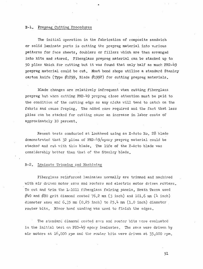
B-l. Prepreg Cutting Procedures
The initial operation in the fabrication of composite sandwich
or solid laminate parts is cutting the prepreg material into various
patterns for face sheets, doublers or fillers which are then arranged
into kits and stored. Fiberglass prepreg material can be stacked up to
50 plies thick for cutting but it was found that only half as much PRD- 9
prepreg material could be cut. Most bond shops utilize a standard Stanley
carton knife (Type #1299, Blade #1992) for cutting prepreg materials.
Blade changes are relatively infrequent when cutting fiberglass
prepreg but when cutting PKD- 9 prepreg close attention must be paid to
the condition of the cutting edge as any nicks will tend to catch on the
fabric and cause fraying. The added care required and the fact that less
plies can be stacked for cutting cause an increase in labor costs of
approximately 10 percent.
Recent tests conducted at Lockheed using an X-Acto No. 28 blade
demonstrated that 32 plies of PRD- 9/epo>:y prepreg material could be
stacked and cut with this blade. The life of the X-Acto blade was
considerably better than that of the Stanley blade.
B-2. Laminate Trimming and Machining
Fiberglass reinforced, laminates normally are trimmed and machined
with air driven motor saws and routers and electric motor driven routers.
To cut and trim the L-1011 fiberglass fairing panels, Heath Tecna used
#^0 and #80 grit diamond coated ?6.2 mm (3 inch) and 101.6 mm (k inch)
diameter saws and 6.35 rora (0.25 inch) to 25«4 mm (l.O inch) diameter
router bits. Minor hand sanding was used to finish the edges.
The standard diamond coated saws and router bits were evaluated
in the initial test on PKD- 9 epoxy laminates. The saws were driven by
air motors at 16,000 rpm and the router bits were driven at 35>000
51

Grit size on the cutting tools had no effect upon the surface
produced, as the tools rapidly became "loaded-up" (coated) with resin and
fiber particles. The 2.5 mm (0.10 inch) thick edge laminates on the
sandwich panels were overheated, the loose fibers smouldered and occasionally
burst into flame, and some delamination was also noted.
Various saw blade and router bit configurations were evaluated at
Systimatic Tool Company, Seattle, Washington. Laminates made from 39U°K
(250 F) and k^O K (350 F) curing epoxy resins were used for the machining
tests.
Carbide tipped saw blades were designed such that the tooth would
draw the edge fibers downward into the laminate as the cutting action
occurred. The saw blades depicted in Figures B-l through B-3 produced the
best results on PKD-^9 epoxy laminates, The blades depicted in Figures
B-l and B-2 produced the cleanest cut (least amount of fabric fraying),
however, the cutting edges dulled rapidly and generated more heat than the
saw blade shown in Figure B-3.
Although blade velocity did not have a significant effect upon the
finish of the cut edge, the tool life was affected. A speed of 6000 rpm
was better than 16,000 rprn in deterring the rather rapid dulling of the
carbide cutting tips.
Depending on the frequency of use of these tools, resharpening could
be required after each day's production run. This necessitates a greater
quantity of tools and a regular, controlled sharpening schedule. With
fiberglass laminates -a diamond coated saw or router bit lasts 6-8 months
when used k-6 hours per cay, five days a week.
The cutting system selected by Heath Tecna as being the most feasible
at this time is a two step operation. The initial cut is made with the
blade shown in Figure B-3, so that an excess of 0.?6-1002 mm (0.030-0.0 0
inch) beyond the standard setback is added to the laminate panel edge.
52

-p<u
ICOH
I
•H
•sfl3O
H
PQ
53

CJCJ
EHl
COH
CO
0)'d•H
Rjo
CM
isO CQ
<J->
i \f
'
V— t-
"T "T
/_^r---j •
I(J
SZ
^CO Oo •• o
CM
u
m —o •
• oco - —

AV
CO
I
•H
•8rOO
dbO•ri
II* o
(J:>z
^ o
X
CN
1 1<— — ' V— J U- I I

The final finish cut to dimension is accomplished with a hand -air motor.j
and a diamond cut carbide router bit, operating at 353000 rpmj. The routing
operation removes the majority of the frayed fibers prior to the final
finish deburring (sanding) operation. This two step trim operation adds
75 percent more labor hours to the trimming time, but it reduces the
additional labor hours required during final deburring. The increase does
not include the cost for additional cutters (approximately $50 each) or
the added resharpening costs (about $7.00) however, these costs are a small
increment when compared to the labor increase.
Hand routing is also used to cut sharp radius areas and cutouts in
the sandwich and solid laminates. When solid carbide end mill cutters
were evaluated for routing, they were found to overheat the PKD-1+9 epoxy
laminate and dull rapidly. Best results were obtained with diamond shaped
cut carbide cutters.
Liquid or gas coolants were not evaluated during this program because
of the difficulty, involved in adapting a continuous flow system to a hand
tool operation. Furthermore, the introduction of liquid coolants may h£ve
a detrimental effect on the laminate due to absorption of the coolant.
The deburring operation is performed after trimming and machining
isi complete. Fiberglass reinforced laminates require only a quick scuff
hand sand for final finishing, however, it appears machine sanding may be
necessary after routing PRD- -9 epoxy composites. A wet and dry
vibrating sander and 100-180 grit sandpaper was used by Heath Tecna. This
incurred a twenty percent increase in the final deburring operation.
Previous independent work at the Lockheed-California Company has
lead to the development of a proprietary tool identified as a "Nibbler"
which incorporates a very close tolerance shearing operation for trimming
contoured laminates. A comparison of cuts by the Nibbler and a standard
fiberglass router is shown in Figure B-'l. Two models, a light duty unit
56

Figure B~J| - Comparison of Cuts by Mbbler(Top) and Standard FiberglassRouter (Bottom). Scale shownis in inches.

for thinner laminates, and a heavy duty unit, have been produced and are
available as standard Lockheed tools. Lockheed is taking steps to make
this tool available under license.
'The heavy duty unit successfully trims laminates up to 3-18 ™a (0.125 inch)
thick. However, the force required to push the Nibbler in this thick material
would fatigue an operator using it all day. It is best suited for cutouts, and
sharp radii and is not recommended for long cuts. Both units have proven to be
better adapted to epoxy resin systems than to phenolics. This can probably be
attributed to the better wetting characteristics of the epoxies, which create
a better bond between fibers and resin. Sanding requirements following trim-
ming with the Nibbler are minimal.
A second tool, evaluated during the installation of panels on Air Canada
and Eastern Air Lines aircraft at Palmdale, is the Black and Decker Porto-Shear.
(See Figures B-5 and B-6). This is a hand held electric motor driven device
utilizing two opposing shear blades which operate on the jigsaw principle. These
units come in l^, l6, and 18 gage models and are available commercially from
Black and Decker. A similar model is available from Rockwell Air Tools. The
16 gage model was used for the trimming operation on the fairing panels. The
60 inch edge of the panels was trimmed in 93 seconds and required little or no
sanding after trim. There was insufficient material cut to evaluate the life of
the shear blades, however, the cutting and sanding time for PRD-^9 and fiberglass
laminates was the same with the Porto-Shear.
Based on,-the above evaluation, Lockheed used the Nibbler and
Porto-Shear to trim heavier PRD- 9/eP°xy laminates on all of the flight
evaluation panels. Further evaluation of the two tools will be conducted
to determine tool life.
B-3. Drilling and Countersinking
Hole drilling and countersinking operations on the L-1011 fairings were
accomplished during the fit check of trimmed panels to the aircraft contour
fixtures at Heath Tecna. The standard drills and controlled depth countersink
tools presently used for fiberglass laminates were not acceptable for PRD- 9/
epoxy laminates.
58

Figure B-5 - Black and Decker Porto-Shear UsedTo Trim Wing-to-Body Fairing PanelDuring Installation
6?
.•(*#-, ,. ,_ . — «r^-^ir,7"-• ~. ' JT -' , • < •Y X*'*?!**,** -'•- j-.*^:--;%»*SA*rSa-*
Figure B-6 - Trimming Wing-to-Body FairingPanel With Porto-Sliear
59

These tools produced badly frayed fastener holes and irregular counter-
sinks. Drill speed variations from 500 to 55000 RPM were of no significant
effect.
Development of an efficient drill point requires a configuration which
draws the fibers inward toward the center and cuts them. This approach was
also taken in the development of the countersink design.
The drill point defined in Figure B-7 was selected for drilling holes in
PRD-U9 laminates. When backed up properly, a clean hole was produced with this
type of drill. Backup material may be provided by clamping a strip of laminate,
relatively hard wood or micarta on the opposite side of the panel from which the
drill enters. All drilling was performed with a standard drill motor operating
at 5000 RPM.
While the special drill just described produced acceptable holes, all the
holes drilled at Lockheed during installation of the panels were drilled with
a Lockheed Standard Stepped Double Margin Drill, shown in Figure B-8. These
drills produced clean sharp holes when properly backed up and. may be reground
until minimum dimensions are reached. Dimensions of the drills are controlled
by NAS 937-
The use of backup blocks will require additional labor for positioning
and seating the blocks. Tool life factors could not be determined since long
term continuous drilling was not performed.
Countersinking - Two countersink configurations were developed during the
program. The tool in Figure B-9 is a general configuration and is applicable to
single or multiflute tools. This tool was successfully used at Heath Tecna for
countersinking the test panels. The standard 100° stop countersink is placed in
a stationary chuck and the 20° relief is ground out by hand with a drill motor
and diamond stone cutter. In a production tool this cut would be made prior to
heat treat.
60

FIGURE B-7
SPECIAL DRILL POINT FOR
PRO-1+9 LAMINATES
FIGURE B-8
STEPPED DOUBLE MARGIN DRILL
61

Figure B-9. Countersink A 4.?6 mm Dia. (0.187 inch)
62
A second configuration was produced by reworking a standard 100
steel countersink as shown in Figure B-10. This tool was used with a
standard countersink stop cage. All of the countersinking operations
at Lockheed were performed using the modified tool shown in Figure B-10,
and there was no evidence of dulling of the tool. Countersink or drill
life should not be a significant factor in the cost differential in-
volving PKD-U9/epoxy, however, many more holes must be prepared before
a definite determination of tool life can be made.
63
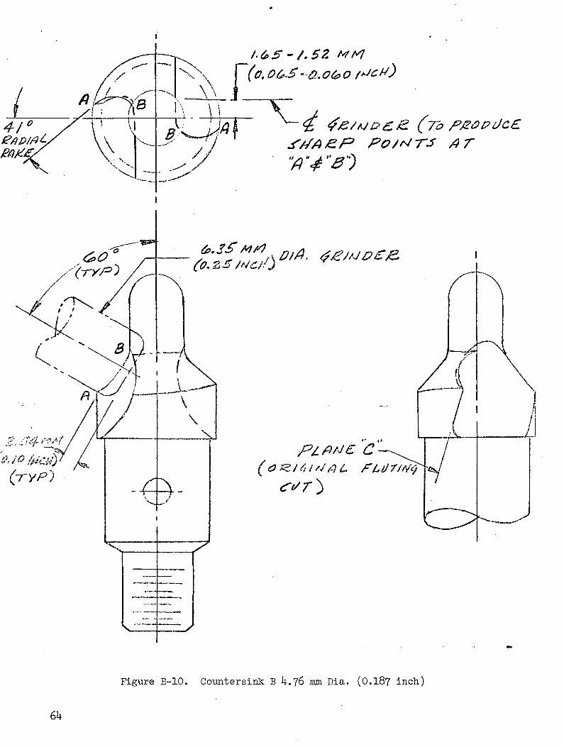
Figure B-10. Coimtersink B 4.76 mm Dia. (0.18? inch)