Embed Size (px)
Citation preview

Installationinstructions
C 556 C 586
www.contura.eu

GB
44
556/586
Quality approval
The stove has been tested by SP, the Swedish National Testing and Research Institute and meets the applicable regulations for CE marking and the stricter requirements for P marking. Manufacture of the product has taken place in accordance with those documents which are the basis for the relevant type approval certification and the required manufacturing checks. The chimney must be dimensioned for at least 350° C for both top connection directly upwards and connection directly backwards from the rear of the stove.
378 001
NORDIC ECOLABEL
378 001
NORDIC ECOLABEL Contura 556/586 is a Swan marked stove.
NIBE was the first stove manufacturer in Sweden to commit to Swan marking their stoves. The Swan mark is one aspect of our vision to be a company of the future, setting high quality standards regarding the environment. Certification number 378-001.
EC Declaration of conformity
Manufacturer
name NIBE AB/NIBE STOVESaddress Box 134, Skulptörvägen 10, SE-285 23 MarkarydPlaceofmanufacture Markaryd, Sweden
PrODuctcOVereDBYtHISDecLaratIOn
Producttype Stove fired by solid fueltypedesignation Conturatypeacc.tostandard EN 13240 annex ZAIntendedforuse Heating of living accomodationfuels Wood logsSpecialconditions None
ce-MarKInG 556 586
nominaloutput 5 kW 5 kWfueltype Wood logs Wood logs fluegastemperature 291° 291°energyefficiency 79% 79%emissionofcO 0,11% 0,11%
appendixLighting and installation instructions
Niklas GunnarssonBusiness area manager NIBE STOVES

GB
45
556/586
Table of contents
Technical details 4
Prior to installation 4
Removing the loose parts 5
Connection to chimney 6
Supply of combustion air/Option 7
Installation distance 556 8
Installation distance 586 9
Installing 556 10
Installing 586 12
A warm welcome to Contura.
A warm welcome to the Contura family. We hope you will get a great deal of pleasure from your new stove. As a new owner of a Contura stove you have secured a product with timeless design and long service life. The Contura is not only an efficient source of heat, but it is environmentally friendly as well.
Read through these installation instructions carefully before installation. Read how to best light your stove in the lighting instructions.
The stove becomes very hotDuring operation, certain surfaces of the stove become very hot and can cause burn injury if touched. Be aware of the strong heat radiated through the hatch glass. Placing flammable material closer than the safe distance indicated may cause a fire. Pyre lighting can cause quick gas ignition with the risk of damage to property and personal injury.
NOTE! WARNING!
Report the installation of a stove to your local authority.
The building owner is personally responsible for ensuring compliance with the mandatory safety requirements and must have the installation approved by a qualified inspector. Your local chimney sweep must also be informed about the installation as this will affect the routines for regular chimney-sweeping services.

GB
46
556/586
FACTS
Output 3-7kWNominal output 5 kWEfficiency up to 79%
Model 556 586 Weight (kg) 105 110 Width (mm) 495 495 Depth (mm) 440 440 Height (mm) 1080 1160
Type approved in accordance with:European standard EN-13240 Swedish environmental and quality marking, P-marking cert. no.220309Norwegian standard NS 3059, SINTEF 043-140German standard DIN Plus, RRF-40 10 2253
Contura 556 Contura 586
Prior to installation
If the insert needs bedding down to be moved or if the pillar foot is to be installed, remove any loose components. When the stove is installed reinstall the components in reverse order.
1 Fire bars2 Grate disc3 Heat deflector4 Hearth cladding (Vermiculite).
1
2
3
4
Installation by authorised technician This manual contains instructions about how the stoves must be assembled and installed. To ensure the function and safety of the stove, we recommend that the installation is carried out by an authorised technician. Contact one of our dealers who can recommend suitable technicians.
Building applicationBefore installing a stove or erecting a chimney it is necessary for you to make a building application permission to your local authority. Ask your local authority for advice regarding building regulations and the application.
Structural supportCheck that the wood joists are strong enough to bear the weight of the stove and chimney. The stove and chimney can usually be placed on a normal wooden joist in a single occupancy house if the total weight does not exceed 400 kg.
Hearth plateDue to the risk of falling embers, the stove must be placed on a non-combustible surface. If the floor under the stove is flammable, it must be protected by a hearth plate which covers at least 300 mm to the front and 100 mm along each side. The hearth plate can consist of natural stone, concrete, metal or glass. A painted metal or glass hearth plate is available as an accessory for these models.
Important to remember!Technical details
GB
47
556/586
REMOVAL
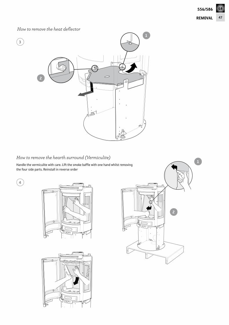
How to remove the hearth surround (Vermiculite)Handle the vermiculite with care. Lift the smoke baffle with one hand whilst removing the four side parts. Reinstall in reverse order
4
3
How to remove the heat deflector
2
1
2
1

GB
48
556/586
CHIMNEY
Connection to chimney
Ø ca 180 mmØ ca 180 mm
Rear connection to a masonry chimney
Top connection to the chimney
Make sure that the connector gasket does not work loose when the connection pipe is placed on the connector. If further sealing material is required, heat-resistant sealant may be used.
The back panel must be installed before the stove is rear connected.
The hot air grille must be installed before chimney top connection.
• The stove meets the requirements for connecting to chimneys dimensioned for 350°C flue gas temperature.
• The external diameter of the connection sleeve is 150 mm.
• The stove requires a draft in the chimney of at least –12 Pa. The draft is affected both by the length and area of the chimney, and by how well sealed it is. Minimum recommended chimney length is 3,5 m and a suitable cross section area is 150-200 cm² (140-160 mm in diameter).
• A flue with sharp bends and horizontal routing reduces the draught in the chimney. Maximum horizontal flue is 1 m, on the condition that the vertical flue length is at least 5 m.
• It must be possible to sweep the full length of the flue and the soot hatches must be easily accessible.
• Carefully check that the chimney is sealed and that there is no leakage around soot hatches and flue connections.
2 31
5 64
!

GB
49
556/586
SUPPLY AIR/ACCESSORY
Supply of combustion airWhen a stove is installed in a room, the air supply demand to the room increases. Air can be provided indirectly via a vent in the outer wall or via a duct from the outside that is connected to the connector on the underneath of the stove. The amount of air needed for combustion is 25m3/h.
The connector has an external diameter of 67 mm. When duct routing further than 1 m the pipe diameter must be increased to 100 mm and a correspondingly larger wall vent must be selected.
In hot areas the duct should be insulated with 30 mm mineral wool covered with a moisture inhibitor (plastic). It is important that the lead-in between the pipe and the wall (or floor) is sealed using jointing compound.
A 1 m length of condensation insulated ducting for combustion air is available as an accessory.
40 m
m
40 m
m
30 m
m
40 m
m
Through the external wall.
Indirect air supply through the external wall.
Through floor and foundation slab.
Through floor and wall-and-cavity foundation.
LEK
C586 There is a detachable cover on the reverse of the pillar foot which is removed when installing combustion air connection.
C556In the back and floor plates there are knockouts that must be removed to insert the pipe.
Installation variantsLeave a 40 mm gap between the condensation insulation and the bottom of the stove.
!

GB
50
556/586
556
1080
495
200
0*
D 37
0
Combustible roof
140
100
B 92
0*
A 10
15*
C 38
0
35
440
Air inlet Ø67
Ø150
750
500
240
100150
250
350
450
50
150
250
350
Combustible wall
410
400
200
100
695
880
Combustible wall
C556
* If the stove is placed on a hearth plate made of glass for example (accessory), the height from the floor is affected by a distance corresponding to the thickness of the hearth plate. Also applies to separate glass hearth plates (accessory).
** To prevent discolouration of painted non-flammable walls, we recommended the same side distance as to combustible walls.
320**
700
1100
70**
190
50
Fire-retardant wall ofbrick or concrete
280
70
565
670
800
800
Fire-retardant wall ofbrick or concrete
The minimum distance in front of the stove opening to combustible parts of the building or interior decoration must be at least 1 m.
When top connecting a steel flue please refer to the relevant manufacturer’s installation instructions. Observe the safety distances to combustible material that steel flues require.
Installation distances
WHEN INSTALLING TURNTABLE (OPTION) the following installation distances do not apply. See the separate turntable instructions.
A = height from floor to chimney connection upwards
B = height from floor to c/c chimney connection rear
C = height from floor to air inlet
D = height from floor to lower edge of hatch
Permitted area for combustible material

GB
51
556/586
586
1160
495
220
0*
Ø 510
D 44
5
Combustible roof
190
B 99
5*
A 10
90*
C 48
5
35
140
440
Air inlet Ø67
Ø150
750
500
240
100150
250
350
450
50
150
250
350
Combustible wall
410
400
200
100
695
880
Combustible wall
C586
* If the stove is placed on a hearth plate made of glass for example (accessory), the height from the floor is affected by a distance corresponding to the thickness of the hearth plate. Also applies to separate glass hearth plates (accessory).
** To prevent discolouration of painted non-flammable walls, we recommended the same side distance as to combustible walls.
320**
700
1100
70**
190
50
Fire-retardant wall ofbrick or concrete
280
70
565
670
800
800
Fire-retardant wall ofbrick or concrete
The minimum distance in front of the stove opening to combustible parts of the building or interior decoration must be at least 1 m.
When top connecting a steel flue please refer to the relevant manufacturer’s installation instructions. Observe the safety distances to combustible material that steel flues require.
Installation distances
WHEN INSTALLING TURNTABLE (OPTION) the following installation distances do not apply. See the separate turntable instructions.
Permitted area for combustible material
A = height from floor to chimney connection upwards
B = height from floor to c/c chimney connection rear
C = height from floor to air inlet
D = height from floor to lower edge of hatch
A separate glass floor plate (accessory) increases the connection height to the chimney by 10mm.Install the spacers supplied with the floor plate prior to connection.
!

GB
52
556/586
556
Installing C556
10
10
VANADIUM
No. 7
CHROME
x 3
10
10
VANADIUM
No. 7CHROME
2
3
1
Wait to tighten the back panel’s upper screws until the side panels are installed.
Clean the side glass thoroughly before installing the side panels.
4
Installing the rating plates C556
The following rating plates must be placed on the underneath of the heat deflector. The heat deflector can be removed and is not used with the fan option. In such a case, place the rating plates on the fan shelf.
!

GB
53
556/586
556
10
10
VANA
DIUM
No. 7
CHRO
ME
6 5
13
13VANADI UM
No. 7CHROME
8
79
It is extremely important that the installation is inspected by an authorised chimney sweep before the stove is used. Also read the ”Lighting instructions”, before lighting for the first time.
Final inspection of the installation
READY!If the stove’s loose components are removed these must be reinstalled in reverse order when the stove is put in place.

GB
54
556/586
586
3 4
Wait to tighten the back panel’s screws until the side panels are installed.
10
10
VANADIUM
No. 7
CHROME
x 3
Do not tighten the screws until the stove has been raised again.
21
Installing the rating plates C586
The following rating plates must be placed on the underneath of the pillar frame.
Installing C586
!

GB
55
556/586
586
Clean the side glass thoroughly before installing the side panels.
5
10
10
VANA
DIUM
No. 7
CHRO
ME
10
10
VANADIUM
No. 7CHROME
8
6
7
9
!
GB
56
556/586
586
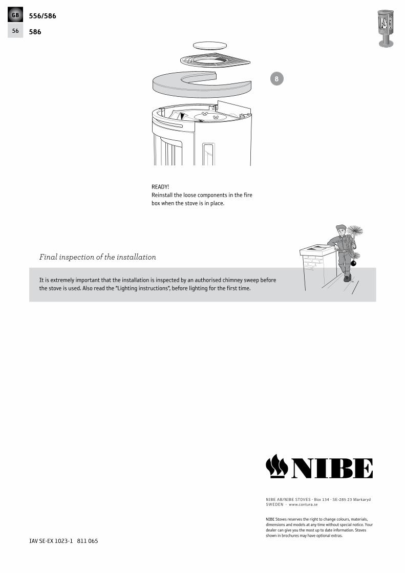
It is extremely important that the installation is inspected by an authorised chimney sweep before the stove is used. Also read the ”Lighting instructions”, before lighting for the first time.
8
Final inspection of the installation
IAV SE-EX 1023-1 811 065
NIBE AB/NIBE STOVES · Box 134 · SE-285 23 MarkarydSWEDEN · www.contura.se
NIBE Stoves reserves the right to change colours, materials, dimensions and models at any time without special notice. Your dealer can give you the most up to date information. Stoves shown in brochures may have optional extras.
READY!Reinstall the loose components in the fire box when the stove is in place.