Embed Size (px)
Citation preview
Subject: INSTALLATION, INSPECTION, AND MAINTENANCE OF CONTROLS FOR GENERAL AVIATION RECIPROCATING AIRCRAFT ENGINES
Date: 6/06/00Initiated By: ACE-100
AC No: 20-143Change:
1. PURPOSE. A review of service history on engine control installations indicates that asignificant percentage of the problems are related to maintenance. Of the control system problemsrelated to maintenance, approximately 75 percent of the problems with these systems result from lackof proper maintenance of airplane manufacturer installed engine controls. The other 25 percent of theservice problems originate from a lack of maintenance of the engine manufacturers’ throttle, mixture,and propeller governor levers/linkages. Most airplane or engine maintenance manuals lack detailedinformation on inspection and installation of engine controls. Therefore, this advisory circular (AC)presents information regarding the inspection, maintenance, and installation of engine controls withemphasis on the airframe portion of these systems. It provides guidance to design and maintenancepersonnel to reduce the number of airplane accidents and incidents related to the loss of engine powercontrol. This material is neither mandatory nor regulatory in nature and does not constitute aregulation. This AC is provided to supplement, but not replace the procedures in the manufacturers'maintenance manuals. Where the content of this AC differs from, or conflicts with, themanufacturer's maintenance manual, instructions contained in the manufacturer's manual takeprecedence over the guidelines provided in this AC.
2. RELATED REGULATIONS. Title 14 Code of Federal Regulations (14 CFR) Part 21,§ 21.50. Airplane airworthiness regulations are specified in 14 CFR Part 23, §§ 23.1141, 23.1143,23.1147, 23.1149, and 23.1529, and the corresponding Civil Air Regulations (CAR) under Part 3.Engine airworthiness regulations are specified in 14 CFR Part 33, §§ 33.4, 33.15 and 33.19, and theircorresponding CAR under Part 13. Propeller airworthiness regulations are specified in 14 CFR Part35, § 35.4, and the corresponding CAR under Part 14. Inspection requirements can be found in 14CFR Part 43, appendix D, and § 43.15(c).
3. BACKGROUND. Current 14 CFR design rules require throttle and mixture controls onsingle reciprocating engine-powered airplanes that will allow continued safe flight and landing in theevent of a control separation at the engine fuel metering device. The current rules (§§ 23.1143(g) and23.1147(b)) are not applicable to older airplanes. This AC has been prepared to address proper

AC 20-143 6/06/00
2
installation, inspection, and maintenance of many different types of engine controls on airplanes oldand new regardless of the rules under which they were certified. General requirements are containedin Part 43, appendix D, which specify the scope and detail of items to be included in annual and 100-hour inspections, of which paragraph (d)(6) states, “Engine controls–for defects, improper travel, andimproper safetying.” This AC will provide expanded guidance for general aviation airplanesequipped with reciprocating engines.
6/06/00 AC 20-143
3
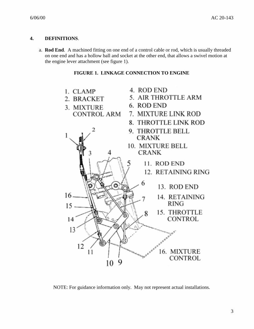
4. DEFINITIONS.
a. Rod End. A machined fitting on one end of a control cable or rod, which is usually threadedon one end and has a hollow ball and socket at the other end, that allows a swivel motion atthe engine lever attachment (see figure 1).
FIGURE 1. LINKAGE CONNECTION TO ENGINE
NOTE: For guidance information only. May not represent actual installations.
AC 20-143 6/06/00
4
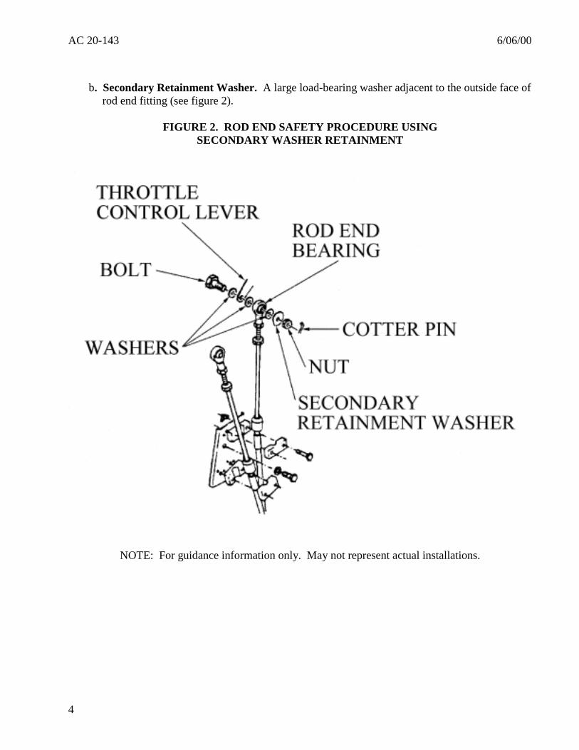
b. Secondary Retainment Washer. A large load-bearing washer adjacent to the outside face ofrod end fitting (see figure 2).
FIGURE 2. ROD END SAFETY PROCEDURE USINGSECONDARY WASHER RETAINMENT
NOTE: For guidance information only. May not represent actual installations.
6/06/00 AC 20-143
5
c. Swaged Joint. A connection of a cable end to a rigid rod or tube (usually by staking orcrimping) that transmits cable motion to the engine control lever.
d. Alternate Air Control. A flexible or rigid control attached to a small door at the carburetorair inlet, or fuel-injector throttle body, that allows entry of heated air or shelteredcompartment air.
e. Fire Sleeve. A protective sleeve covering (e.g., steel, aluminum, asbestos) added to a controlcable or rod end connection that provides local heat or fire protection.
5. INSPECTION PROCEDURE - GENERAL. The need for the correct installation of theengine control cable, attaching hardware, and fuel system component levers and linkages cannot beoveremphasized. The use of approved attachment procedures and techniques is required to assureproper operation and to prevent accelerated wear.
CAUTIONReplacement of rotatable powerplant controls capable of knob rotation at theinstrument panel with non-rotatable solid shaft controls is discouraged. Solidshaft controls (non-rotatable at the instrument panel knob) have been founddisconnected at the rod end as a result of pilots attempting to adjust a frictionlock without realizing that the knob was also being rotated. Solid shaftpowerplant controls may be replaced with rotatable knob controls whenacceptable data exists.
a. In the absence of specific inspection intervals, repetitive inspections of the engine controls inthe nacelle and cockpit areas should be conducted as part of the annual and 100-hourinspections described in Part 43, appendix D.
b. Inspect all engine control cables for proper tension, routing, security, and signs of damagecaused by chafing and heat distress. Improper installation of cables will significantly reducetheir service life.
c. In addition to the throttle and mixture controls, inspect the operation of each engine-relatedcontrol such as the propeller, carburetor heat, alternate air, and cowl flap controls asapplicable. Make certain that each control has full limit of travel, and that no binding orexcessive play caused by worn parts or improper installation is evident.
d. Apply simulated air loads by manually pressing on cowl flaps and alternate air controls toensure cables are not slipping in support clamps. Check for looseness of throttle, mixture, andpropeller controls to ensure proper security of these components.
e. Replace all control cables, levers, link rods, and attaching hardware found damaged or wornbeyond acceptable service limits. Engine-related levers, link rods, and attaching hardwareshould be installed in accordance with the instructions provided in the applicable aircraft orengine maintenance manuals. Consult the airframe/engine manufacturer’s published
AC 20-143 6/06/00
6
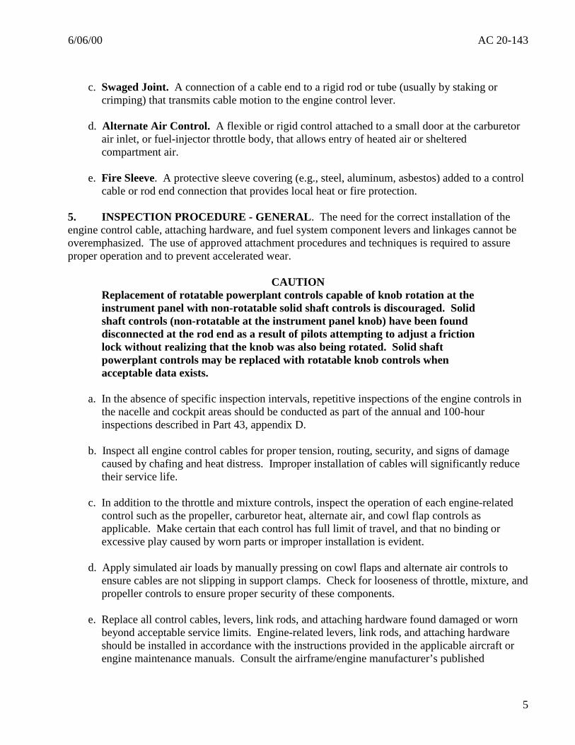
instructions for routing and attachment of the various engine-related control cables.Attachment of components that have relative motion should be accomplished by using bolts(screws) drilled for cotter pins, using castellated nuts, cotter pins, and large secondary washerretention devices. (See figures 1, 2, and 3.)
WARNING:
Connections requiring torque fasteners should not exhibitany relative movement or motion between components.
FIGURE 3. CABLE RETENTION METHOD
NOTE: For guidance information only. May not represent actual installations.
6/06/00 AC 20-143
7
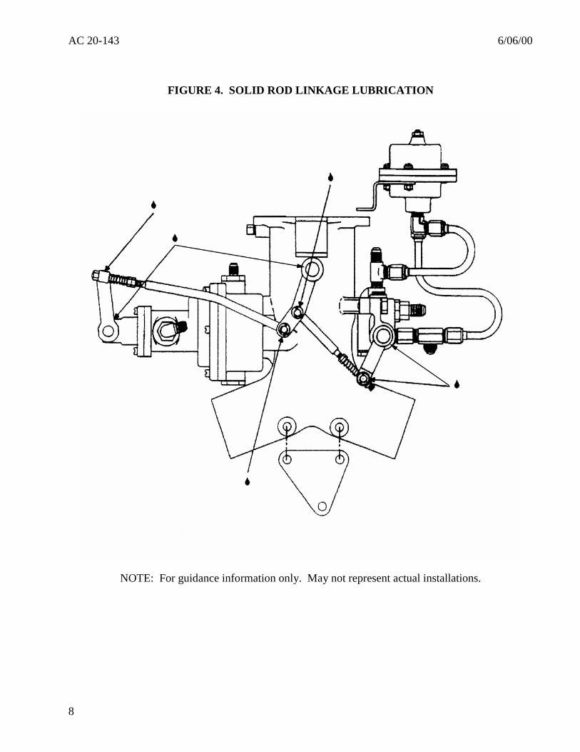
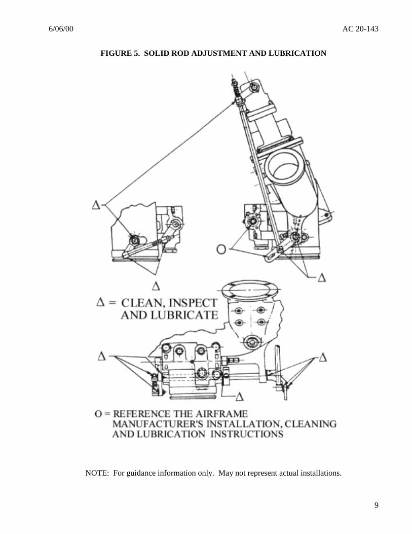
6. LUBRICATION OF CONTROL RODS, LINKAGES, AND JOINTS (see figures 4 and 5).Damage and wear to the actuating components of engine control systems can be attributed toimproper (or the lack of) lubrication. During scheduled and unscheduled maintenance, engines arenormally cleaned using a solvent or soap solution pressure wash. This tends to remove lubricationfrom fuel system levers, linkages, and bushings. Therefore, it is necessary that these areas belubricated after engine cleaning and during scheduled maintenance as indicated in the followingparagraphs:
a. Consult with the airplane and engine manufacturers, plus the control cable manufacturer ifnecessary, for published instructions covering powerplant control cable service-life limits andattach-point inspection, repair, installation, and lubrication.
b. Inspect the pivot points of the levers and linkages for dirt, wear, and rust, and replace asnecessary. Direct cleaning of these areas may be necessary to remove contaminationincluding a buildup of old grease or oil. After cleaning with clean solvent or soap solution,dry each area using compressed air.
AC 20-143 6/06/00
8
FIGURE 4. SOLID ROD LINKAGE LUBRICATION
NOTE: For guidance information only. May not represent actual installations.
6/06/00 AC 20-143
9
FIGURE 5. SOLID ROD ADJUSTMENT AND LUBRICATION
NOTE: For guidance information only. May not represent actual installations.
AC 20-143 6/06/00
10
c. Lubrication of control cables (including pressure lubrication) should not be attempted withouta specific approved procedure. Engine controls without an approved procedure should bepermanently tagged. Pressure lubrication should not be performed on any control without anapproved procedure. Contact the airframe or engine manufacturer for additional guidance.
d. Use proper tools and holding devices when installing, adjusting, or removing controls andfittings. Avoid using tongue and groove pliers or locking grip pliers. Failure to use theproper tools may result in crushed or bent engine control components.
e. In the absence of specific lubrication information from the manufacturer, it is acceptable toapply LPS 2®, Permatex “Maintain®” Lubricant, or equivalent, to each pivot point, includingthrottle shaft bushings. If parts such as a lever or link rod are to be replaced or reassembled,initial lubrication may be accomplished by using Shell Number 5 grease, or LUBRIPLATE®,Number 630AA, or equivalent.
NOTE. These lubricants function well in cold weather. However, airplanes operating in extremelycold conditions may be better off with little or no lubricant on the control levers, linkages, andbushings.
6/06/00 AC 20-143
11
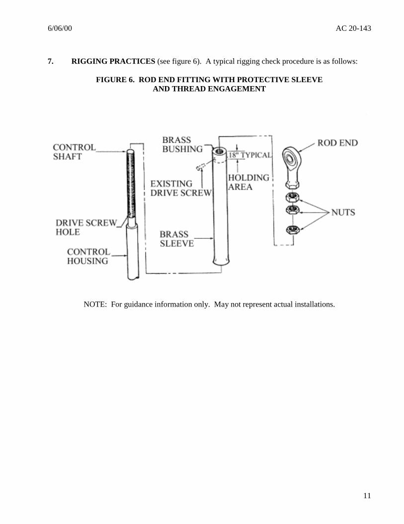
7. RIGGING PRACTICES (see figure 6). A typical rigging check procedure is as follows:
FIGURE 6. ROD END FITTING WITH PROTECTIVE SLEEVEAND THREAD ENGAGEMENT
NOTE: For guidance information only. May not represent actual installations.
AC 20-143 6/06/00
12
a. The appropriate airplane and engine manuals, and service bulletins, should be consulted foreach installation.
b. Examine the alignment of the accessory end (engine end) of the control, ensuring that theaccessory unit operating arm does not cause binding or bending of the control cable, push rod,or swivel fitting.
c. Ensure that there is freedom of movement of rod-end fittings and clevis-fork fittingsthroughout their entire range of travel.
d. Ensure that any threaded shank has at least the minimum required thread engagement.
e. Rig engine controls in a manner leaving 1/16- to 1/8-inch of unused travel in the full throttle,full rich, or maximum r.p.m. position. This is achieved by having the accessory unit controlarm against its travel stop, while the engine control knob in the cockpit has 1/16- to 1/8-inchmargin before contacting its stop.
8. INSTALLATION VERIFICATION. After proper installation, lubrication, and rigginghave been accomplished, the following should be verified:
a. Each control should be able to maintain any necessary position without constant attention bythe pilot or without tendency to creep due to control loads, or vibration (see § 23.1141(c)).
b. Each control should permit full limit of travel and have the required safety or locking devicein place. There should be no binding of levers, linkages, control rods, or cables. Thereshould be freedom of movement unrestricted by contact with other parts or components thatare located in close proximity.
c. Verify that separation between engine controls and exhaust system components is consistentwith the manufacturer’s guidelines, or are secured as far away from each other as possible.Ensure that heat shields are installed in accordance with the manufacturer’s instructions.
d. Check fuel system flow (after mixture control, shutoff valve, or selector valve linkageinstallation) and adjust, as required, in accordance with the engine/airplane manufacturers’applicable maintenance manual or service bulletin instructions.
6/06/00 AC 20-143
13
9. Appendix 1 provides supplemental illustrations for inspection, maintenance, and installation ofengine lever and cable controls. These figures are for guidance only and may not represent actualinstallations.
S/ Marvin Nuss for
Michael GallagherManager, Small Airplane DirectorateAircraft Certification Service

6/06/00 AC 20-143Appendix 1
1
APPENDIX 1SUPPLEMENTAL ILLUSTRATIONS
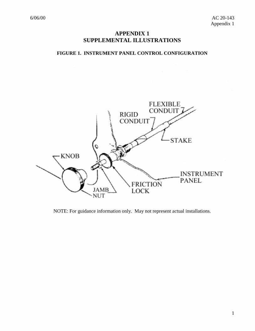
FIGURE 1. INSTRUMENT PANEL CONTROL CONFIGURATION
NOTE: For guidance information only. May not represent actual installations.
AC 20-143 6/06/00Appendix 1
2
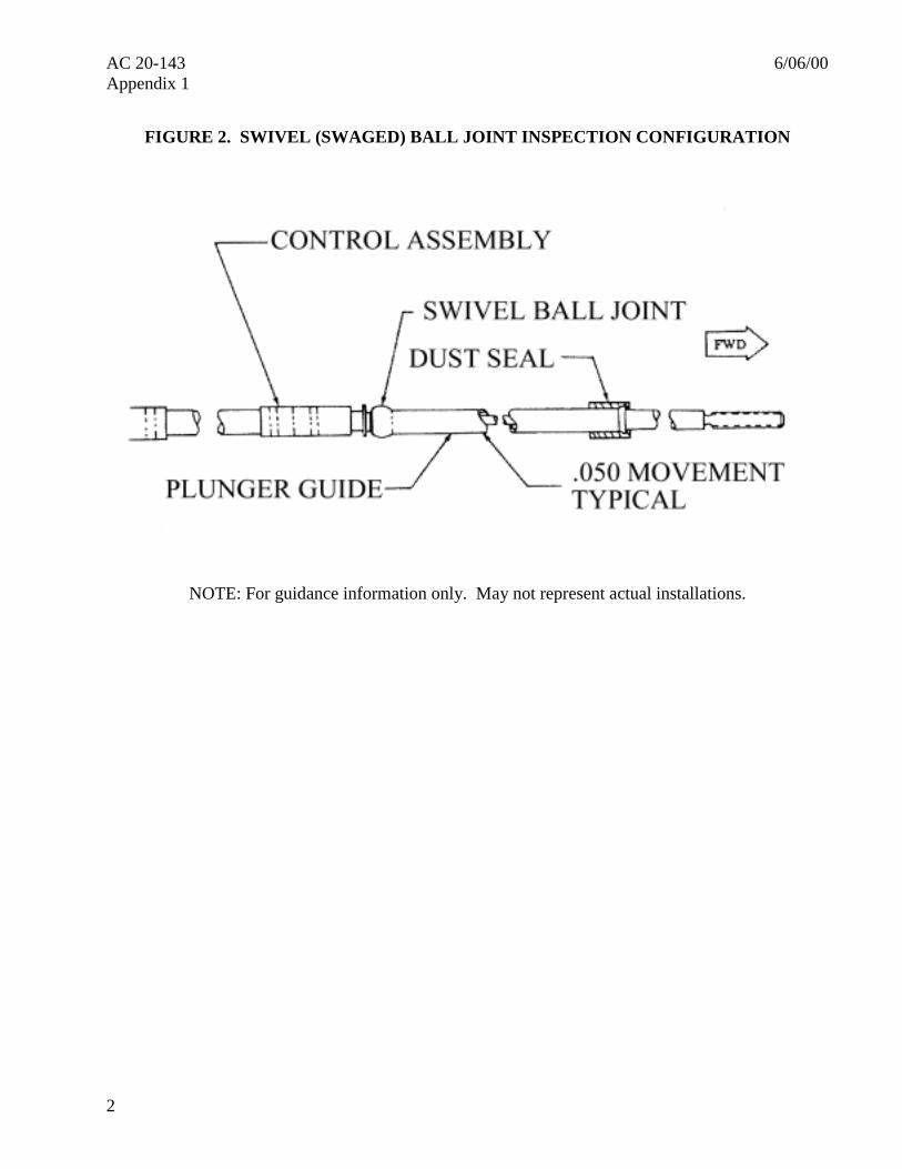
FIGURE 2. SWIVEL (SWAGED) BALL JOINT INSPECTION CONFIGURATION
NOTE: For guidance information only. May not represent actual installations.
6/06/00 AC 20-143Appendix 1
3
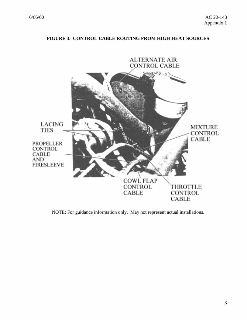
FIGURE 3. CONTROL CABLE ROUTING FROM HIGH HEAT SOURCES
NOTE: For guidance information only. May not represent actual installations.
AC 20-143 6/06/00Appendix 1
4
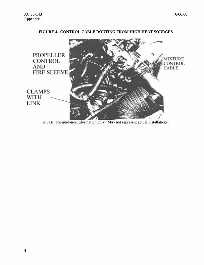
FIGURE 4. CONTROL CABLE ROUTING FROM HIGH HEAT SOURCES
NOTE: For guidance information only. May not represent actual installations.
6/06/00 AC 20-143Appendix 1
5
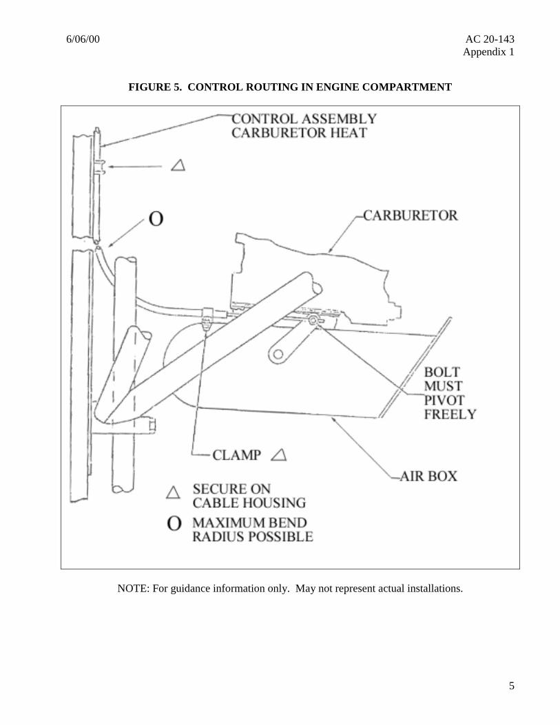
FIGURE 5. CONTROL ROUTING IN ENGINE COMPARTMENT
NOTE: For guidance information only. May not represent actual installations.
AC 20-143 6/06/00Appendix 1
6
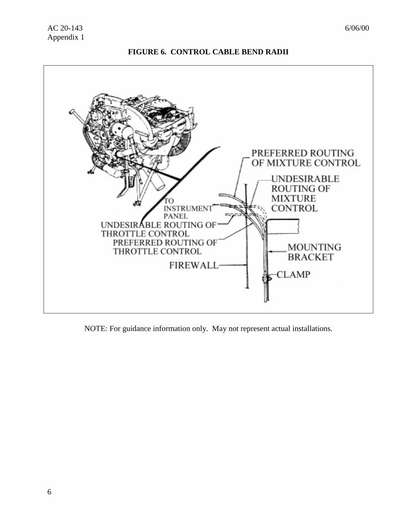
FIGURE 6. CONTROL CABLE BEND RADII
NOTE: For guidance information only. May not represent actual installations.
6/06/00 AC 20-143Appendix 1
7
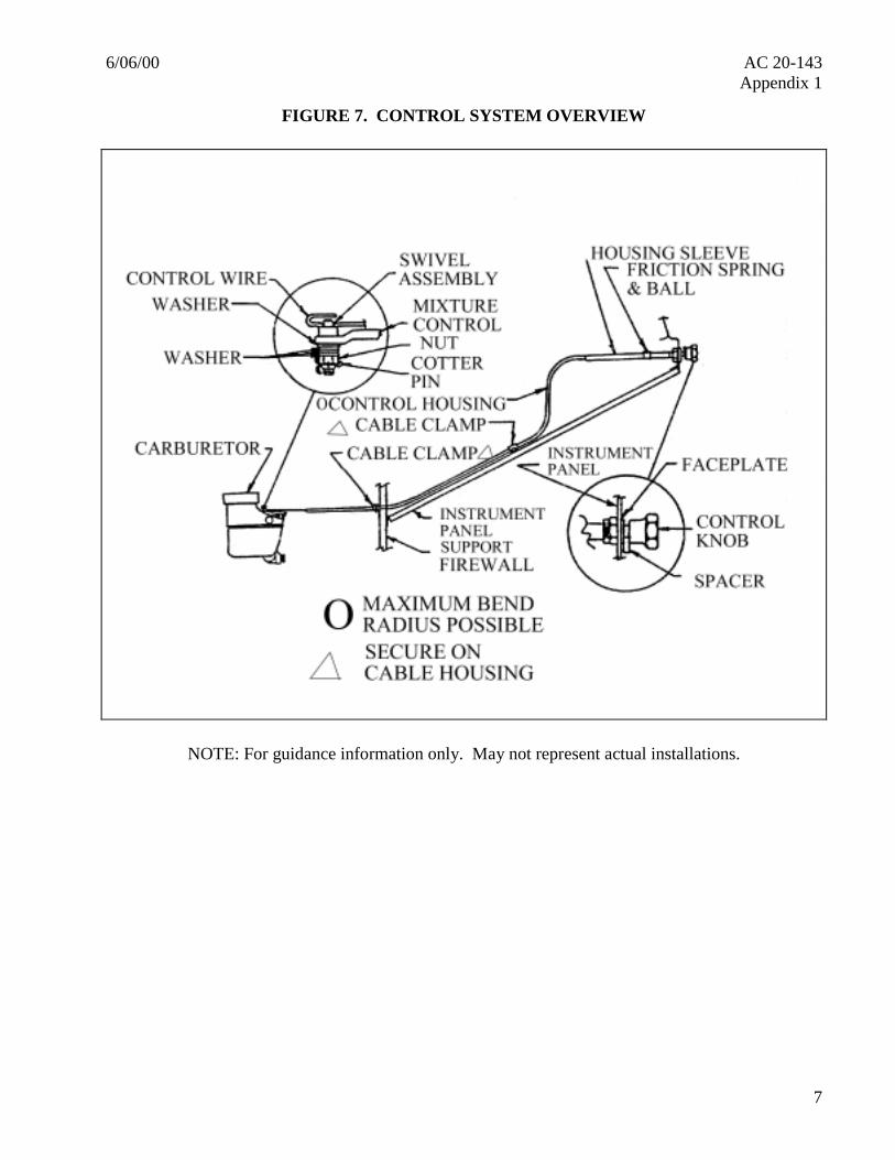
FIGURE 7. CONTROL SYSTEM OVERVIEW
NOTE: For guidance information only. May not represent actual installations.
AC 20-143 6/06/00Appendix 1
8
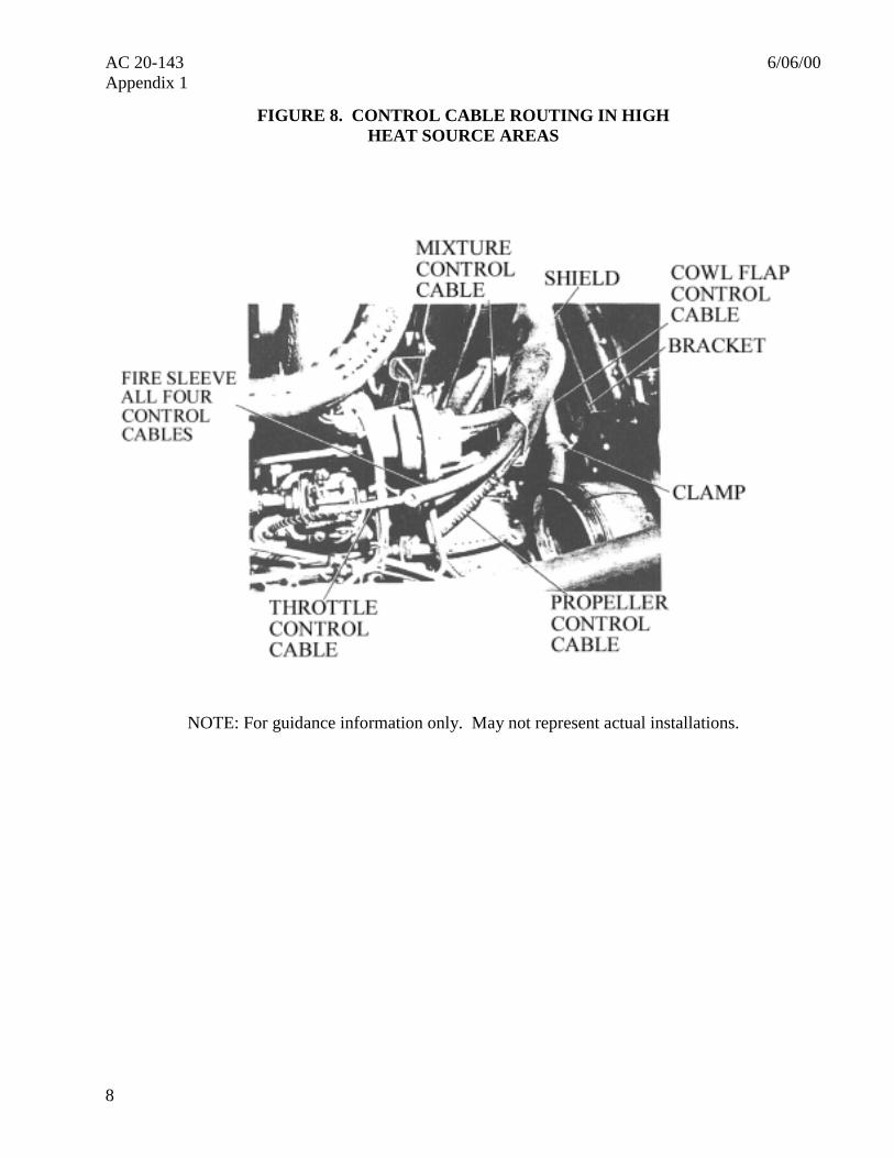
FIGURE 8. CONTROL CABLE ROUTING IN HIGHHEAT SOURCE AREAS
NOTE: For guidance information only. May not represent actual installations.
6/06/00 AC 20-143Appendix 1
9
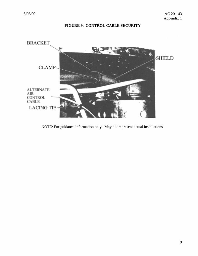
FIGURE 9. CONTROL CABLE SECURITY
NOTE: For guidance information only. May not represent actual installations.