Embed Size (px)
Citation preview
Manufacturer reserves the right to discontinue, or change at any time, specifications or designs without notice and without incurring obligations.Catalog No. 18-40VMD001-01 Printed in U.S.A. Form 40VMD-3SI Pg 1 3-18 Replaces: 40VMD-2SI
Installation and Maintenance Instructions
CONTENTSPage
SAFETY CONSIDERATIONS . . . . . . . . . . . . . . . . . .1,2GENERAL . . . . . . . . . . . . . . . . . . . . . . . . . . . . . . . . . 2, 3INSTALLATION . . . . . . . . . . . . . . . . . . . . . . . . . . . . 4-12Step 1 — Unpack and Inspect Units . . . . . . . . . . . . 4• PROTECTING UNITS FROM DAMAGE• PREPARING JOBSITE FOR UNIT INSTALLATION• IDENTIFYING AND PREPARING UNITSStep 2 — Position the Unit . . . . . . . . . . . . . . . . . . . . 4Step 3 — Mount the Unit . . . . . . . . . . . . . . . . . . . . . . 4• INSTALLING HANGER BOLTS• MOUNTING UNITStep 4 — Connect Piping . . . . . . . . . . . . . . . . . . . . . . 5• CONDENSATE PIPING• REFRIGERANT PIPING• PIPING BETWEEN MDC AND INDOOR UNIT• TWINNING MDC PORTS• PIPING BETWEEN MDC AND SUB MDC• PIPING BETWEEN MDC AND OUTDOOR UNITELECTRICAL REQUIREMENTS . . . . . . . . . . . . 14-17Opening the Electrical Control Box . . . . . . . . . . . . 14Complete Electrical Connections. . . . . . . . . . . . . 15MDC UNIT ADDRESSING . . . . . . . . . . . . . . . . . . . 18Setting the Unit Address . . . . . . . . . . . . . . . . . . . . 18Merged Port Setting. . . . . . . . . . . . . . . . . . . . . . . . 18TROUBLESHOOTING . . . . . . . . . . . . . . . . . . . 18, 18LED Indication Lamp Instructions . . . . . . . . . . . . 18Error Code . . . . . . . . . . . . . . . . . . . . . . . . . . . . . . . 18SW8/SW9 Query Instruction . . . . . . . . . . . . . . . . . 19TEST RUN . . . . . . . . . . . . . . . . . . . . . . . . . . . . . . . . 19APPENDIX A — DIP SWITCH SETTINGS. . . . . . . . 20
SAFETY CONSIDERATIONS
Improper installation, adjustment, alteration, service,maintenance, or use can cause explosion, fire, electrical shock,or other conditions which may cause death, personal injury orproperty damage. The qualified installer or agency must usefactory authorized kits or accessories when modifying thisproduct.
Follow all safety codes. Wear safety glasses, protectiveclothing, and work gloves. Use quenching cloth for brazingoperations. Have fire extinguisher available. Read theseinstructions thoroughly and follow all warnings or cautionsincluded in literature and attached to the unit. Consult localbuilding codes and the current editions of the NationalElectrical Code (NEC) ANSI/NFPA (American NationalStandards Institute/National Fire Protection Association) 70.For Canada, refer to the current editions of the CanadianElectrical Code CSA (Canadian Standards Association) C22.1.
Understand the signal words — DANGER, WARNING,and CAUTION. DANGER identifies the most serious hazardswhich will result in severe personal injury or death.WARNING signifies hazards that could result in personal
injury or death. CAUTION is used to identify unsafe practices,which could result in minor personal injury or product andproperty damage.
Recognize safety information. This is the safety-alertsymbol ( ). When this symbol is displayed on the unit and ininstructions or manuals, be alert for the potential of personalinjury. Installing, starting up, and servicing the equipment canbe hazardous due to system pressure, electrical components,and equipment location.
WARNING
Electrical shock can cause personal injury and death. Shutoff all power to this equipment during installation. Theremay be more than one disconnect switch. Tag alldisconnect locations to alert others not to restore poweruntil work is completed.
WARNING
When installing the equipment in a small space, provideadequate measures to avoid refrigerant concentrationexceeding safety limits due to refrigerant leak. In case ofrefrigerant leak during installation, ventilate the spaceimmediately. Failure to follow this procedure may lead topersonal injury.
WARNING
DO NOT USE TORCH to remove any component. Systemcontains oil and refrigerant under pressure. To remove a component, wear protective gloves andgoggles and proceed as follows:a. Shut off electrical power to unit.b. Recover refrigerant to relieve all pressure from
system using both high-pressure and low pressureports.
c. Traces of vapor should be displaced with nitrogenand the work area should be well ventilated.Refrigerant in contact with an open flame producestoxic gases.
d. Cut component connection tubing with tubing cutterand remove component from unit. Use a pan to catchany oil that may come out of the lines and as a gagefor how much oil to add to the system.
e. Carefully unsweat remaining tubing stubs whennecessary. Oil can ignite when exposed to torchflame.
Failure to follow these procedures may result in personalinjury or death.
40VMD006-016Multiport Distribution Controller for
Variable Refrigerant Flow (VRF) Systems
2
GENERAL
The 40VMD multiport distribution controller (MDC) is adistribution box for refrigerant to multiple indoor fan coil unitsinstalled in a given heat recovery system.
The equipment is initially protected under themanufacturer’s standard warranty; however, the warranty isprovided under the condition that the steps outlined in thismanual for initial inspection, proper installation, regularperiodic maintenance, and everyday operation of the unit befollowed in detail. This manual should be fully reviewed inadvance before initial installation, start-up and anymaintenance. Contact your local sales representative or thefactory with any questions BEFORE proceeding.
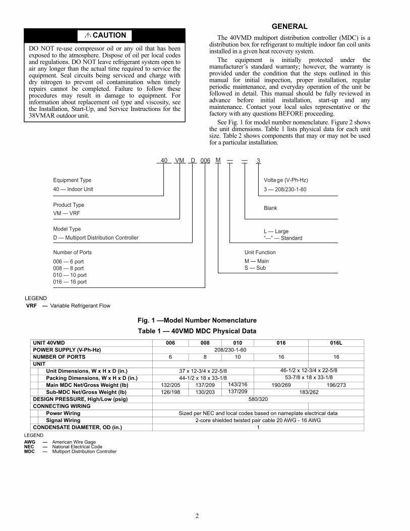
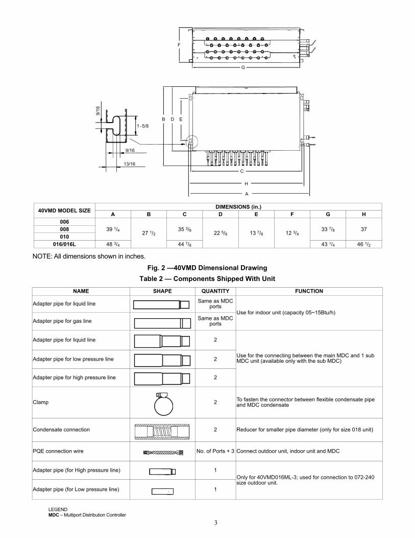
See Fig. 1 for model number nomenclature. Figure 2 showsthe unit dimensions. Table 1 lists physical data for each unitsize. Table 2 shows components that may or may not be usedfor a particular installation.
Fig. 1 —Model Number Nomenclature
Table 1 — 40VMD MDC Physical Data
LEGEND
CAUTION
DO NOT re-use compressor oil or any oil that has beenexposed to the atmosphere. Dispose of oil per local codesand regulations. DO NOT leave refrigerant system open toair any longer than the actual time required to service theequipment. Seal circuits being serviced and charge withdry nitrogen to prevent oil contamination when timelyrepairs cannot be completed. Failure to follow theseprocedures may result in damage to equipment. Forinformation about replacement oil type and viscosity, seethe Installation, Start-Up, and Service Instructions for the38VMAR outdoor unit.
UNIT 40VMD 006 008 010 016 016LPOWER SUPPLY (V-Ph-Hz) 208/230-1-60NUMBER OF PORTS 6 8 10 16 16UNIT
Unit Dimensions, W x H x D (in.) 37 x 12-3/4 x 22-5/8 46-1/2 x 12-3/4 x 22-5/8
Packing Dimensions, W x H x D (in.) 44-1/2 x 18 x 33-1/8 53-7/8 x 18 x 33-1/8
Main MDC Net/Gross Weight (lb) 132/205 137/209 143/216 190/269 196/273Sub-MDC Net/Gross Weight (lb) 126/198 130/203 137/209 183/262
DESIGN PRESSURE, High/Low (psig) 580/320CONNECTING WIRING
Power Wiring Sized per NEC and local codes based on nameplate electrical dataSignal Wiring 2-core shielded twisted pair cable 20 AWG - 16 AWG
CONDENSATE DIAMETER, OD (in.) 1
—40 VM D 006 3
40 — Indoor Unit
Product TypeVM — VRF
Volta ge (V-Ph-Hz)
3 — 208/230-1-60
Blank
Model TypeD — Multiport Distribution Controller
Equipment Type
Number of Ports006 — 6 port
010 — 10 port008 — 8 port
016 — 16 port
—
L — Large“—” — Standard
M
Unit FunctionM — MainS — Sub
LEGENDVRF — Variable Refrigerant Flow
AWG — American Wire GageNEC — National Electrical CodeMDC — Multiport Distribution Controller
3
Fig. 2 —40VMD Dimensional Drawing
Table 2 — Components Shipped With Unit
NAME SHAPE QUANTITY FUNCTION
Adapter pipe for liquid line Same as MDC ports
Use for indoor unit (capacity 05~15Btu/h)
Adapter pipe for gas line Same as MDC ports
Adapter pipe for liquid line 2
Use for the connecting between the main MDC and 1 sub MDC unit (available only with the sub MDC)Adapter pipe for low pressure line 2
Adapter pipe for high pressure line 2
Clamp 2 To fasten the connector between flexible condensate pipe and MDC condensate
Condensate connection 2 Reducer for smaller pipe diameter (only for size 018 unit)
PQE connection wire No. of Ports + 3 Connect outdoor unit, indoor unit and MDC
Adapter pipe (for High pressure line) 1Only for 40VMD016ML-3; used for connection to 072-240 size outdoor unit.
Adapter pipe (for Low pressure line) 1
NOTE: All dimensions shown in inches.
40VMD MODEL SIZEDIMENSIONS (in.)
A B C D E F G H006
39 1/427 1/2
35 3/822 5/8 13 7/8 12 3/4
33 7/8 37008010
016/016L 48 3/4 44 7/8 43 1/4 46 1/2
A
C
B E
F
G
D1 -5/8
9/16
H
13/16
9/16
.
LEGENDMDC – Multiport Distribution Controller

4
INSTALLATION
Step 1 — Unpack and Inspect Units — Units arepackaged for shipment to avoid damage during normal transitand handling. It is the receiving party’s responsibility to inspectthe equipment upon arrival. Any obvious damage to the cartonand/or its contents should be reported on the bill of lading and aclaim should be filed with the transportation company and thefactory. Unit should always be stored in a dry place, and in theproper orientation as marked on the carton.
After determining the condition of the carton exterior,carefully remove each unit from the carton and inspect forhidden damage. Any hidden damage should be recorded, aclaim should be filed with the transportation company, and thefactory should be notified. In the event a claim for shippingdamage is filed, the unit, shipping carton, and all packing mustbe retained for physical inspection by the transportationcompany. All units should be stored in the factory shippingcarton with internal packaging in place until installation.PROTECTING UNITS FROM DAMAGE
Do not apply force or pressure to the piping or drain stub-outs during handling. All units should be handled by thechassis or as close as possible to the unit mounting pointlocations.
The unit must always be properly supported. Temporarysupports used during installation or service must be adequate tohold the unit securely. To maintain warranty, protect unitsagainst hostile environments (such as rain, snow or extremetemperature), theft, vandalism, and debris on jobsite.Equipment covered in this manual is not suitable for outdoorinstallations. Do not allow foreign material to fall into drainpan. Some units and/or job conditions may require some formof temporary covering during construction.PREPARING JOBSITE FOR UNIT INSTALLATION
To save time and to reduce the possibility of costly errors,set up a complete sample installation in a typical room atjobsite. Check all critical dimensions such as pipe and wireconnection requirements. Refer to job drawings and productdimension drawings as required. Instruct all trades in their partsof the installation. Units must be installed in compliance withall applicable local code requirements.IDENTIFYING AND PREPARING UNITS
Be sure power requirements match available power source.Refer to unit nameplate and wiring diagram. In addition:
• Check all tags on unit to determine if shipping screws areto be removed. Remove screws as directed.
Step 2 — Position the Unit
Install the unit in a location that meets the followingrequirements:
• Allow adequate space for installation, service clearance,piping, and electrical connections. For specific unit
dimensions, refer to Table 1 and Fig. 2. Allow clearanceaccording to local and national codes.
• Confirm that the ceiling is able to support the weight ofthe unit. See Table 1 for nominal weight.
• There should be enough room within the false ceiling forinstallation and maintenance (see Fig. 3).
• The false ceiling should be horizontal and leveled.
• See Fig. 3 below.
Select the unit position with the following points in mind:
• The unit should be installed in a position that is suitableto support the total weight of the unit, refrigerant pipingand condensate.
• Proper access should be provided for maintenance forrefrigerant piping, A 2-ft clearance is recommended allaround the unit for service.
• The unit should not be positioned directly above anyobstruction.
• The unit must be installed square and level.
• The condensate drain should have sufficient downwardslope (1 in. per 100 in.) in any horizontal run betweenunit and drain.
Step 3 — Mount the UnitINSTALLING HANGER BOLTS — Install the hanger boltsat the locations shown in Fig. 2, top view. Use 3/8-in. all-threaded rod. For unit weight, see Table 1.
MOUNTING UNIT — The unit can now be lifted on to thehanging rods for mounting.1. Use rods and fasteners to suspend the unit at the factory-
provided mounting holes. 2. Adjust the height of the unit until the bottom is level with
the false ceiling, with adequate space to provide enoughpitch for the drain.
3. Secure the unit in position with locknuts and washers onboth sides of the mounting bracket. Ensure that thethreaded rod does not protrude more than 2 inches belowthe mounting brackets as shown in Fig. 4.
CAUTION
To avoid equipment damage, do not lift unit by the drainpipe or refrigerant piping. Unit should be lifted using themounting brackets.
DANGER
Units must not be installed where they may be exposed topotentially explosive or flammable atmosphere. If thisinstruction is not followed exactly, a fire or explosion mayresult, causing property damage, injury, or loss of life.
IMPORTANT: Be sure that the ceiling grid is supportedseparately from the unit. The ceiling grid must not besupported by any part of the unit or any associatedwiring or piping work.
3 7/8[100]or more or more
27 1/2[700] or more
(Unit: in.[mm])
19- 5/8[500] or more
19 5/8[500]
Fig. 3 — False Ceiling Required Clearance

5
Fig. 4 —Threaded Rod
Step 4 — Connect PipingCONDENSATE PIPING — The unit is supplied with a 1 inches OD drain connection to connect copper or PVC drain piping as shown in Fig. 5.
When installing condensate piping, follow these recommendations:
• Condensate piping should slope downward in thedirection of condensate flow, with a minimum gradientof 1 in. per 100 inches.
• Condensate piping must not be installed where it may beexposed to freezing temperatures.
• Condensate pipe hangers should be spaced 59 in. or lessbetween hangers.
• For additional recommendations see Fig. 6.
REFRIGERANT PIPING
When connecting refrigerant piping follow theseprocedures:
• The refrigerant piping should be dry and free of dust andother impurities.
• The number of bends in the refrigeration piping must befewer than 15.
• The bending angle of the refrigerant pipe should notexceed 90 degrees and the bending radius should be aslarge as possible to prevent any breakage in piping.
• Use a torque wrench for flare nuts. Refer to Table 3 forflare nut torque recommendations.
Table 3 — Flare Nut Torque Recommendations
• Before connecting any piping to the MDC cut the tips offevery gas and liquid pipe of the MDC unit to release thegas in the system as shown in Fig. 7, even if the pipe isnot being used for this installation.
PIPING BETWEEN MDC AND INDOOR UNIT —
When connecting indoor units to an MDC follow theseprocedures:
• Check maximum height drop and length of refrigerantpiping between the indoor units and MDC. To ensure thedrop and length are acceptable, refer to the refrigerantpiping allowable limits in the manual.
• Refrigerant piping connection between indoor unitsshould be performed once the units are secured at theirrespective installation locations.
• The refrigeration piping starts at the indoor unit and endsat the MDC.
• Before insulating the suction and liquid refrigerationpipes, perform pressure and leak tests. For details, seethe outdoor unit installation manual. Insulating bothsuction and liquid refrigerant pipes is mandatory.
• Vacuuming and charging of the system should be carriedout as described in the outdoor unit installation manual.
CAUTION
Multiport Distribution Controller’s (MDCs) are shippedfrom the factory with brazed caps on all lines andpressurized with nitrogen to keep the system clean.Cutting the tip relieves the pressure in the system. Cutall the tips on the MDC piping prior to removing anybrazed caps. Failure to cut the tip before removing thebrazed cap may cause equipment damage or personalinjury.
a40-1722
Fig. 5 — Connecting the Condensate Drain
(1[ 25])
Hard PVC binderCondensate outlet
pipe
Drain pan Clamp Condensate connection PVC water
Fig. 6 — Space Required for Condensate Drain Installation
Pipe hanger
59”or lessRefrigerant pipe
(Gradient: 1 in. per 100 in.)Minimum 2” Ceiling
7 7/8” or more
59” or less
Outside Diameter (in.) Recommended Torque (ft-lb)1/4 153/8 261/2 415/8 48
CAUTION
MDCs are shipped from the factory with brazed caps onall lines and pressurized with nitrogen to keep thesystem clean. Failure to remove the brazed cap beforeconnecting piping will result in equipment malfunctionor damage.
Fig. 7 — Cutting the Tip off the Gas and Liquid Lines
c
a b
LEGEND
a — Brazed Capb — Cut Herec — MDC Unit

6
• Before connecting piping between the indoor units andthe MDC remove the brazed cap as shown in Fig. 8.Depending on the size of the connecting pipe the brazedcap may be left on or removed.
Fig. 8 —Removing the Brazed Cup
• Table 4 shows the piping diameters to use whenconnecting the indoor units and the MDC.
• Table 5 and 6 show how to connect the liquid and gaslines to the indoor units.
• Table 7 shows the number of indoor units that can beconnected to the MDC and sub MDC.
Table 4 — Piping Diameter Between MDC and Indoor Units
Table 5 — Connecting Gas Pipes to the Indoor Unit
LEGEND
Table 6 — Connecting Liquid Pipes to the Indoor Unit
LEGEND
Table 7 — Combination Table
INDOOR UNIT (kBtu/h) LIQUID SIDE (in.) GAS SIDE (in.)5, 7, 9, 12, 15 1/4 1/2
18, 24, 30, 36, 48, 54 3/8 5/872 3/8 7/8
96 3/8 7/8
a
c
b
LEGEND
a — Cut Hereb — Brazed Capc — MDC Unit
INDOOR UNIT
CAPACITY(kBtu/h)
CONNECTION DIAGRAM
5, 7, 9, 12, 15
18, 24, 27, 30, 36, 48, 54
a — MDC Unitb — Pipe Accessoryc — Pipe 1/2d — Pipe 5/8
INDOOR UNIT CAPACITY
(kBtu/h)CONNECTION DIAGRAM
5, 7, 9, 12, 15
18, 24, 27, 30, 36, 48, 54
a — MDC Unitb — Pipe Accessoryc — Pipe 1/4d — Pipe 3/8
b ca
da
b ca
da
MDC IMAGE MAIN MDC
MAX NUMBER OF INDOOR
UNITS CONNECTED TO MAIN MDC
MAX NUMBER OF SUB MDC
MAX NUMBER OF INDOOR
UNITS CONNECTED TO SUB MDC
MAX CAPACITY OF TOTAL INDOOR UNIT (kBtu/h)
MAIN MDC SUB MDC (1) SUB MDC (2)
006 12
2 24 324 126 168
008 16
010 20
016 32
016L 32 504
7
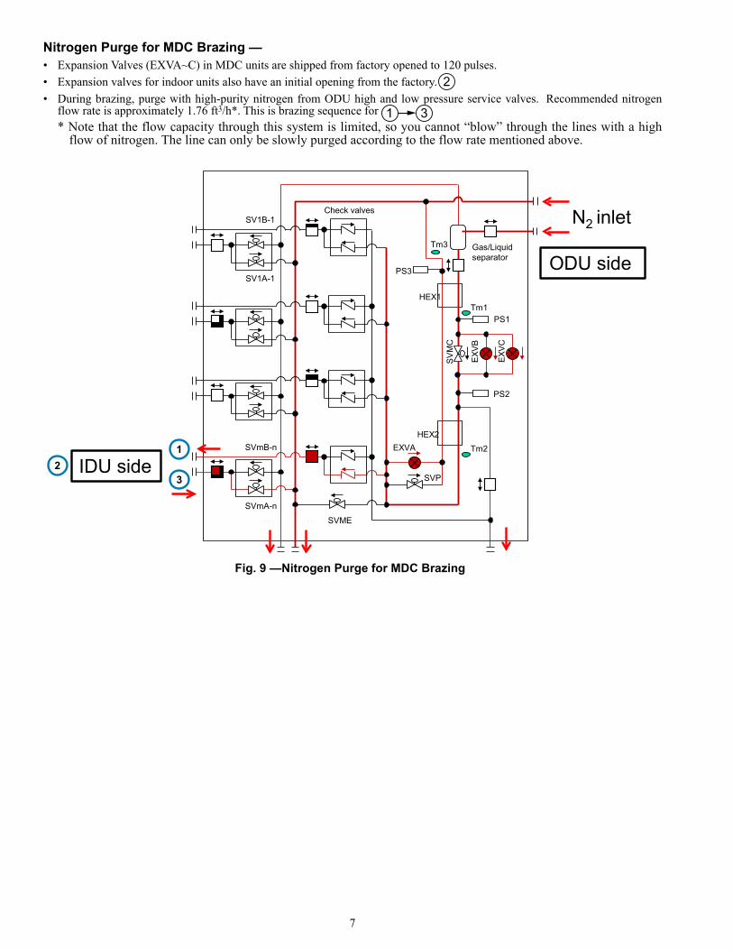
Nitrogen Purge for MDC Brazing — • Expansion Valves (EXVA~C) in MDC units are shipped from factory opened to 120 pulses.
• Expansion valves for indoor units also have an initial opening from the factory.
• During brazing, purge with high-purity nitrogen from ODU high and low pressure service valves. Recommended nitrogenflow rate is approximately 1.76 ft3/h*. This is brazing sequence for * Note that the flow capacity through this system is limited, so you cannot “blow” through the lines with a high
flow of nitrogen. The line can only be slowly purged according to the flow rate mentioned above.
2
1 3
Gas/Liquid separator
Tm3
Tm1
Tm2S
VM
C
EXV
B
EXV
C
SVME
SVP
EXVA
SV1A-1
SV1B-1
SVmA-n
SVmB-n
HEX1
HEX2
Check valves
PS2
PS1
PS3 ODU side
IDU side1
23
N2 inlet
Fig. 9 —Nitrogen Purge for MDC Brazing

8
TWINNING MDC PORTS
For indoor units with capacities greater than 54 kBtu/h, twoMDC ports must be twinned using the Y-joint to create a singleport. The two ports to be paired should be next to each other.Refer to Y-joint “G” in the piping layout; see Fig. 10. The firstport of the pair should have an odd number and second portshould be the next sequential even number. For example: 1 and2, 3 and 4, or 5 and 6 and so on. You cannot pair 2 and 3, 4 and5, or 6 and 7.
Table 8 shows the pipe diameters to use when connectingthe MDC and the Y-joint.
Table 8 — Piping Between the MDC and Y-Joint
PIPING BETWEEN MDC AND SUB MDC — 3 pipes areused to connect the main MDC and the sub MDC. Selection ofthe Sub MDC should follow the requirements of Table 9. Forconnecting the sub MDC to main MDC, use the high pressure,low pressure and liquid pipes as shown in Fig. 10 and 11.
Table 9 —Sub MDC Selection
CAUTION
Connecting an indoor unit with a capacity greater than54 kBtu/h may result in damage to equipment.
TOTAL CAPACITY OF INDOOR UNITS
(kBtu/h)
LIQUID PIPE (in.)
GAS PIPE (in.)
> 54 3/8 5/8
LEGEND
Fig. 10 — Twinning Ports with the Y-Joint
G — Y-Joint
MDC
GG
MDC
GG
CORRECT
INCORRECT
MAIN MDC MODEL SUB MDC UNIT006 006
008006008
010006008010
016/016L
006008010016
9
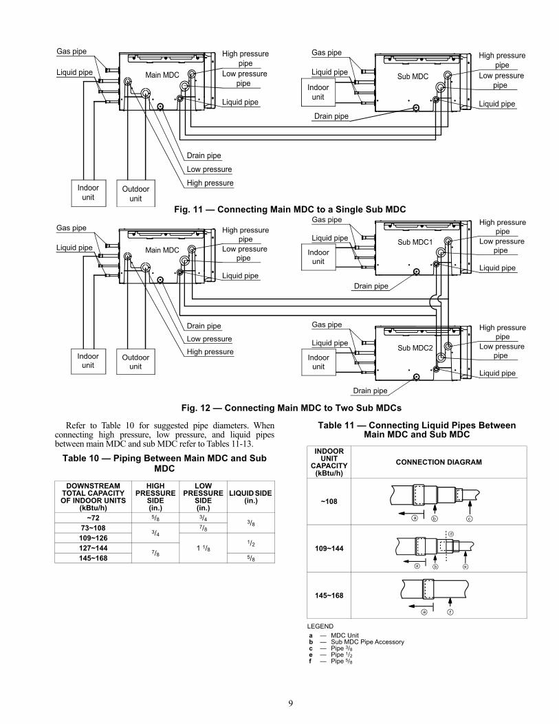
Refer to Table 10 for suggested pipe diameters. Whenconnecting high pressure, low pressure, and liquid pipesbetween main MDC and sub MDC refer to Tables 11-13.
Table 10 — Piping Between Main MDC and Sub MDC
Table 11 — Connecting Liquid Pipes Between Main MDC and Sub MDC
LEGEND
Main MDC
unitOutdoorIndoor
unit
Sub MDCIndoor
unit
High pressurepipe
pipeLow pressure
Liquid pipe
High pressurepipe
pipeLow pressure
Liquid pipe
Drain pipe
Low pressure
High pressure
Drain pipe
Gas pipe
Liquid pipe
Gas pipe
Liquid pipe
Fig. 11 — Connecting Main MDC to a Single Sub MDC
Fig. 12 — Connecting Main MDC to Two Sub MDCs
Main MDC
unitOutdoor
unitIndoor
Sub MDC1
Sub MDC2
unitIndoor
Indoorunit
High pressurepipe
pipeLow pressure
Liquid pipe
High pressurepipe
pipeLow pressure
Liquid pipe
High pressurepipe
pipeLow pressure
Liquid pipe
Drain pipe
Low pressure
High pressure
Drain pipe
Gas pipe
Liquid pipe
Gas pipe
Liquid pipe
Gas pipe
Liquid pipe
Drain pipe
DOWNSTREAM TOTAL CAPACITY OF INDOOR UNITS
(kBtu/h)
HIGH PRESSURE
SIDE(in.)
LOWPRESSURE
SIDE (in.)
LIQUID SIDE (in.)
~72 5/8 3/4 3/873~108
3/47/8
109~1261 1/8
1/2127~144
7/8145~168 5/8
INDOOR UNIT
CAPACITY(kBtu/h)
CONNECTION DIAGRAM
~108
109~144
145~168
a — MDC Unitb — Sub MDC Pipe Accessoryc — Pipe 3/8e — Pipe 1/2f — Pipe 5/8
b ca
a b
d
e
a f
10
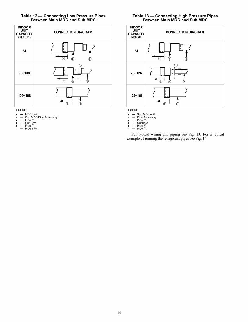
Table 12 — Connecting Low Pressure Pipes Between Main MDC and Sub MDC
LEGEND
Table 13 — Connecting High Pressure Pipes Between Main MDC and Sub MDC
LEGEND
For typical wiring and piping see Fig. 13. For a typicalexample of running the refrigerant pipes see Fig. 14.
INDOOR UNIT
CAPACITY(kBtu/h)
CONNECTION DIAGRAM
72
73~108
109~168
a — MDC Unitb — Sub MDC Pipe Accessoryc — Pipe 3/4d — Cut Heree — Pipe 7/8f — Pipe 1 1/8
b ca
a b
d
e
a f
INDOOR UNIT
CAPACITY(kbtu/h)
CONNECTION DIAGRAM
72
73~126
127~168
a — Sub MDC unitb — Pipe Accessoryc — Pipe 5/8d — Cut heree — Pipe 3/4f — Pipe 7/8
b ca
a b
d
e
a f
11
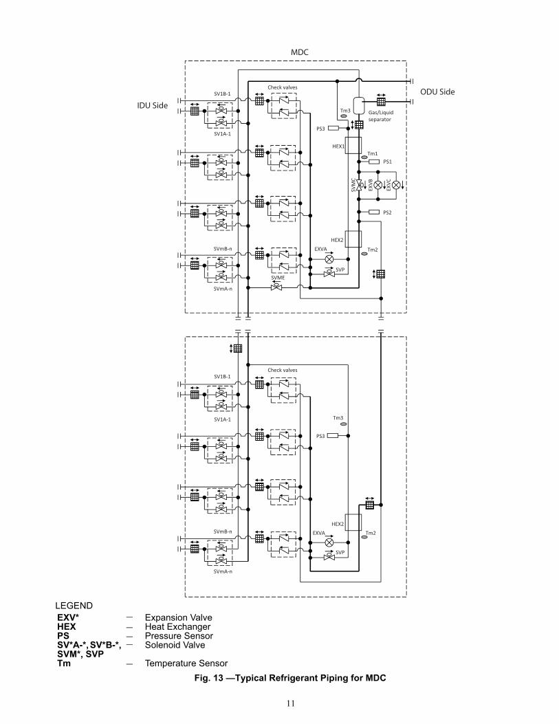
LEGEND
Fig. 13 —Typical Refrigerant Piping for MDC
EXV* — Expansion ValveHEX — Heat ExchangerPS — Pressure SensorSV*A-*, SV*B-*, SVM*, SVP
— Solenoid Valve
Tm — Temperature Sensor
Check valves
PS3
Tm2
SVP
EXVA
Tm3SV1A-1
SV1B-1
SVmA-n
SVmB-nHEX2
separatorGas/Liquid Tm3
Tm1
Tm2
SVM
C
EXVB
EXVC
SVMESVP
EXVA
SV1A-1
SV1B-1
SVmA-n
SVmB-n
HEX1
HEX2
Check valves
PS2
PS1
PS3
IDU Side
ODU Side
MDC
12
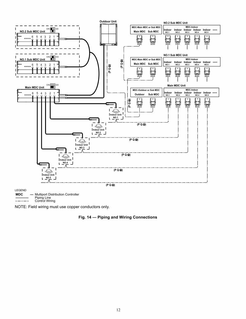
Fig. 14 — Piping and Wiring Connections
LEGEND
NOTE: Field wiring must use copper conductors only.
MDC — Multiport Distribution Controller———— Piping Line- — - — - Control Wiring
Outdoor Unit
Main MDC UnitMDC-Indoor
NO.1Indoor
NO.2Indoor
NO.3Indoor
NO.4Indoor
NO.5Indoor
S8ON
NO.2Indoor Unit
NO.1 Sub MDC UnitMDC-Indoor
NO.1Indoor
NO.2Indoor
NO.3Indoor
NO.4Indoor
NO.5Indoor
MDC-Outdoor or Sub MDC
Outdoor Sub MDC
NO.1 Sub MDC Unit
6 5 4 3 12
Main MDC Unit
Indoor UnitNO.3
NO.4Indoor Unit
NO.1Indoor Unit
S8ON
6 5 4 3 2 1
MDC-Main MDC or Sub MDC
Main MDC Sub MDC
(P Q )
(P Q )
(P Q )
(P Q )
NO.2 Sub MDC UnitS8ON
6 5 4 3 2 1
NO.2 Sub MDC UnitMDC-Indoor
NO.1Indoor
NO.2Indoor
NO.3Indoor
NO.4Indoor
NO.5Indoor
MDC-Main MDC or Sub MDC
Main MDC Sub MDC
NO.5Indoor Unit
(P Q )
13
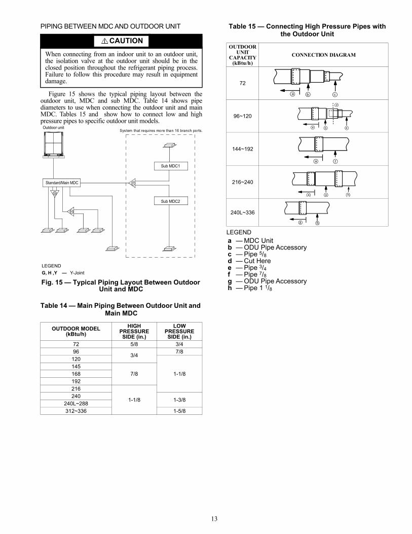
PIPING BETWEEN MDC AND OUTDOOR UNIT
Figure 15 shows the typical piping layout between theoutdoor unit, MDC and sub MDC. Table 14 shows pipediameters to use when connecting the outdoor unit and mainMDC. Tables 15 and show how to connect low and highpressure pipes to specific outdoor unit models.
Table 14 — Main Piping Between Outdoor Unit and Main MDC
Table 15 — Connecting High Pressure Pipes with the Outdoor Unit
LEGEND
CAUTION
When connecting from an indoor unit to an outdoor unit,the isolation valve at the outdoor unit should be in theclosed position throughout the refrigerant piping process.Failure to follow this procedure may result in equipmentdamage.
OUTDOOR MODEL (kBtu/h)
HIGH PRESSURE SIDE (in.)
LOW PRESSURE SIDE (in.)
72 5/8 3/496
3/47/8
120
1-1/8145
7/8168192216
1-1/8240
1-3/8240L~288312~336 1-5/8
LEGEND
Fig. 15 — Typical Piping Layout Between Outdoor Unit and MDC
G, H ,Y — Y-Joint
Outdoor unit
Standard/Main MDC
Sub MDC1
Sub MDC2
F
G
H
System that requires more than 16 branch ports.
OUTDOOR UNIT
CAPACITY(kBtu/h)
CONNECTION DIAGRAM
72
96~120
144~192
216~240
240L~336
a — MDC Unitb — ODU Pipe Accessoryc — Pipe 5/8d — Cut Heree — Pipe 3/4f — Pipe 7/8g — ODU Pipe Accessoryh — Pipe 1 1/8
a b
d
e
a f
a g h
a h
b ca

14
Table 16 — Connecting Low Pressure Pipes with the Outdoor Unit
LEGEND
ELECTRICAL REQUIREMENT
Installation of wiring must conform with local buildingcodes and with National Electric Code ANSI/NFPA 70, currenteditions. Units must be electrically grounded in conformancewith the code. In Canada, wiring must comply with CSAC22.1, Electrical Code.
This equipment in its standard form is designed for anelectrical supply of 208/230-1-60. Any damage to or failure ofunits caused by incorrect wiring or voltage is not covered bywarranty.
Electric wiring must be sized to carry the full load ampdraw. See Table 17 for main unit electrical data and Table 18for sub unit electrical data.
Table 17 — 40VMD Main MDC Electrical Data
Table 18 — 40VMD Sub MDC Electrical Data
LEGEND
Opening the Electrical Control Box Cover —Follow the steps below when removing the top cover.1. Remove the screws as shown in Fig. 16.
OUTDOOR UNIT CAPACITY
(kBtu/h)CONNECTION DIAGRAM
72
96
120~216
240
240L~288
312~336
a — MDC Unitb — ODU Pipe Accessoryc — Pipe 3/4d — Cut Heree — Pipe 7/8f — Pipe 1-1/8g — ODU Pipe Accessoryh — Pipe 1-3/8k — Pipe 1-5/8
WARNING
Electrical shock can cause personal injury and death.Disconnect power supply before making wiringconnections. There may be more than one disconnectswitch. Tag all disconnect locations to alert others not torestore power until work is completed.
WARNING
All units must be wired strictly in accordance with thewiring diagram furnished with the unit. Any wiringdifferent from the wiring diagram could result in personalinjury and property damage.
b ca
a b
d
e
a f
a g h
a j h
D
a j k
CAUTION
Any original factory wiring that requires replacement mustbe replaced with wiring material having a temperaturerating of at least 105 C.Ensure supply voltage to the unit, as indicated on the serialplate, is not more than 10% over the rated voltage or 10%under the rated voltage.Failure to follow these recommendations may result inequipment damage.
40VMD MDC UNIT SIZEPOWER SUPPLY
MCA MOPD006 0.73
15008 0.89010 1.05
016/016L 1.54
MCA — Minimum Circuit AmpsMOPD — Maximum Overcurrent
Protective Device
40VMD SUB MDC UNIT SIZE
POWER SUPPLYMCA MOPD
006 0.69
15008 0.85010 1.01016 1.49
MCA — Minimum Circuit AmpsMOPD — Maximum Overcurrent
Protective Device
Fig. 16 — Removing the Top Cover Screws
15
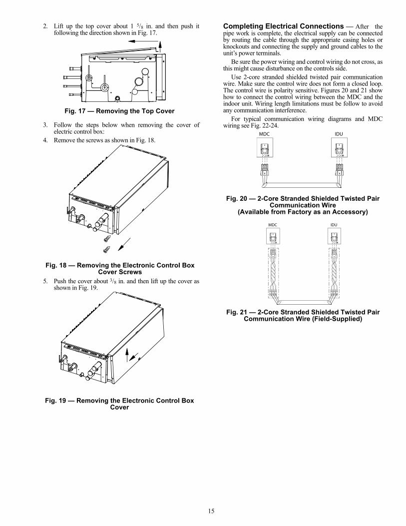
2. Lift up the top cover about 1 5/8 in. and then push itfollowing the direction shown in Fig. 17.
3. Follow the steps below when removing the cover ofelectric control box:
4. Remove the screws as shown in Fig. 18.
5. Push the cover about 3/8 in. and then lift up the cover asshown in Fig. 19.
Completing Electrical Connections — After thepipe work is complete, the electrical supply can be connectedby routing the cable through the appropriate casing holes orknockouts and connecting the supply and ground cables to theunit’s power terminals.
Be sure the power wiring and control wiring do not cross, asthis might cause disturbance on the controls side.
Use 2-core stranded shielded twisted pair communicationwire. Make sure the control wire does not form a closed loop.The control wire is polarity sensitive. Figures 20 and 21 showhow to connect the control wiring between the MDC and theindoor unit. Wiring length limitations must be follow to avoidany communication interference.
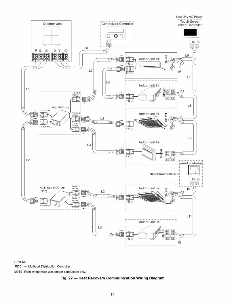
For typical communication wiring diagrams and MDCwiring see Fig. 22-24.
Fig. 17 — Removing the Top Cover
Fig. 18 — Removing the Electronic Control Box Cover Screws
Fig. 19 — Removing the Electronic Control Box Cover
Fig. 20 — 2-Core Stranded Shielded Twisted Pair Communication Wire
(Available from Factory as an Accessory)
P Q P Q
MDC IDU
Fig. 21 — 2-Core Stranded Shielded Twisted Pair Communication Wire (Field-Supplied)
P Q P Q
MDC IDU
16
LEGEND
NOTE: Field wiring must use copper conductors only.
MDC — Multiport Distribution Controller
Fig. 22 — Heat Recovery Communication Wiring Diagram
P Q X Y
X Y
Indoor unit 1#
Indoor unit 2#
Indoor unit 3#
Indoor unit 4#
Indoor unit 5#
Indoor unit 6#
Outdoor Unit Centralized Controller
No.N Sub MDC unit(
Touch ScreenWired Controller
HA HB
HA H
B
HA H
BH
A HB
HA H
BP Q
P Q
P Q
P Q
P Q
P Q
wired controller
HA HB
To No.1indoor
To No.2indoor
To No.3indoor
To No.1indoor
To No.2indoor
To outdoor
To Sub MDC
To outdoor
L1
L2
L3
L3
L3
L3
L3
L5
L6
L7
L10
L11
Main MDC unit
L4
P Q
HA H
B
L8
L9
HA H
B
Note:Power from IDU
Note:24v AC Power
17
To outdoor or MDC unitscommunication bus To indoor units communication bus
OutdoorIndoor No. 1
/Main MDC Sub MDC P Q
M-O M-O CN16 CN3
1(M-I) 2(M-I) 3(M-I) 4(M-I) 5(M-I) 6(M-I) 7(M-I) 8(M-I) CN57 CN58 CN59 CN60
CN28
CN29
CN19
CN21
CN22
TRA
NS
OU
T2
TRA
NS
OU
T1 T
RA
NS
IN1
TRA
NS
IN2
CN17 CN24 CN26
S8
SW8 SW9
S1 S3 S5 S7DSP1 DSP2
CN
53C
N52
CN
51EX
VAEX
VB
EXV
CC
N27
WATER
T3
CN
25T1
T2 C
N20
ONCN42CN43
CN41CN44
CN40 CN39 CN38 CN37 CN36 CN35 CN34 CN33
P QIndoor No. 2
P QIndoor No. 3 Indoor No. 4
P QIndoor No. 5 P Q
Indoor No. 6 P Q
Indoor No. 7 P Q P Q
Indoor No. 8
L1 L2
Power in
To indoor units communication bus
M-O M-O CN10 CN12
CN51
TRA
NS
OU
T TR
AN
S IN
CN53
CN55
S3
CN
41 EX
VA
T3 C
N1
CN
45 T1 T2
CN43
CN44
XT1
1(M-I) 2(M-I) CN13
ON
P QIndoor No. 9 Indoor No. 10
P Q
The
wiri
ng p
ictu
re s
how
n is
for r
efer
ence
onl
y, a
ctua
l pro
duct
may
var
y.
CN27CN29
P Q P Q
Green
ON ON ON ON
S8
ON
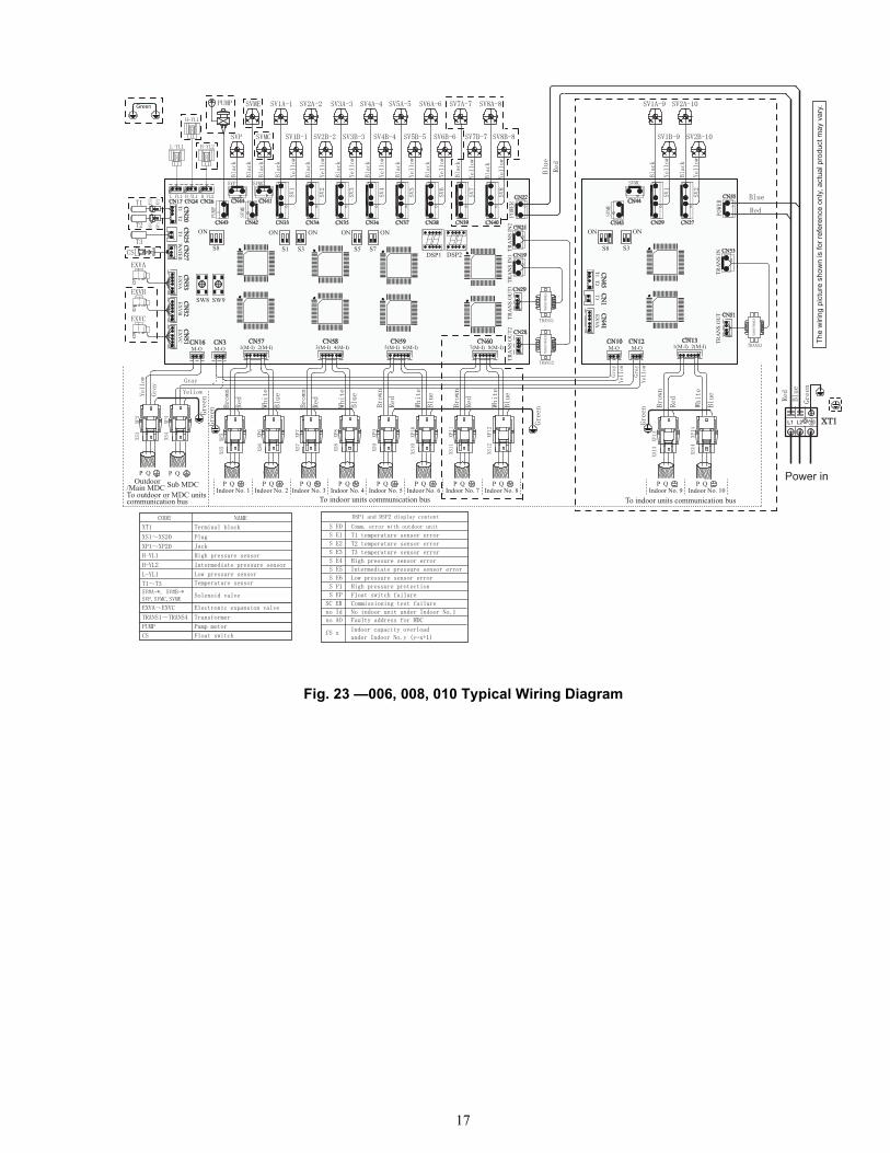
Fig. 23 —006, 008, 010 Typical Wiring Diagram
18
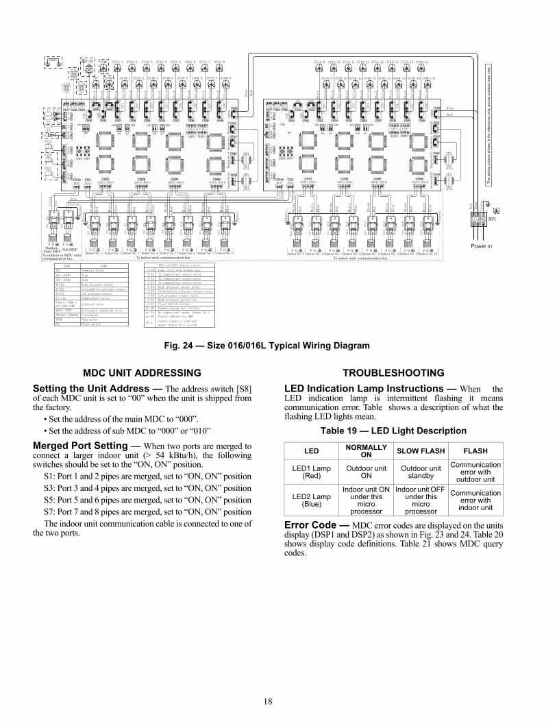
MDC UNIT ADDRESSING
Setting the Unit Address — The address switch [S8]of each MDC unit is set to “00” when the unit is shipped fromthe factory.
• Set the address of the main MDC to “000”.• Set the address of sub MDC to “000” or “010”
Merged Port Setting — When two ports are merged toconnect a larger indoor unit (> 54 kBtu/h), the followingswitches should be set to the “ON, ON” position.
S1: Port 1 and 2 pipes are merged, set to “ON, ON” positionS3: Port 3 and 4 pipes are merged, set to “ON, ON” positionS5: Port 5 and 6 pipes are merged, set to “ON, ON” positionS7: Port 7 and 8 pipes are merged, set to “ON, ON” positionThe indoor unit communication cable is connected to one of
the two ports.
TROUBLESHOOTING
LED Indication Lamp Instructions — When theLED indication lamp is intermittent flashing it meanscommunication error. Table shows a description of what theflashing LED lights mean.
Table 19 — LED Light Description
Error Code — MDC error codes are displayed on the unitsdisplay (DSP1 and DSP2) as shown in Fig. 23 and 24. Table 20shows display code definitions. Table 21 shows MDC querycodes.
Fig. 24 — Size 016/016L Typical Wiring Diagram
L1 L2
Power inTo outdoor or MDC unitscommunication bus To indoor units communication bus
Outdoor /Main MDC Sub MDC
Indoor No. 1 P Q
To indoor units communication bus
M-O M-OCN16 CN3
1(M-I) 2(M-I) 3(M-I) 4(M-I) 5(M-I) 6(M-I)CN57
7(M-I) 8(M-I)CN58 CN59 CN60
CN28
CN29
CN19
CN21
CN22
TRA
NS
OU
T2TR
AN
S O
UT1
TRA
NS
IN1
TRA
NS
IN2
CN17 CN24 CN26
SW8 SW9
DSP1 DSP2
CN
53C
N52
CN
51EX
VAEX
VB
EXV
CC
N27
WATER
T3C
N25
CN
20T1
T2
M-O M-OCN16 CN3
1(M-I) 2(M-I) 3(M-I) 4(M-I) 5(M-I) 6(M-I) 7(M-I) 8(M-I)CN57 CN58 CN59 CN60
CN28
CN29
CN19
CN21
CN22
TRA
NS
OU
T2TR
AN
S O
UT1
TRA
NS
IN1
TRA
NS
IN2CN42CN43
CN41CN44CN17 CN24 CN26
SW8 SW9
DSP1 DSP2
CN
53C
N52
CN
51EX
VAEX
VB
EXV
CC
N27
WATER
T3C
N25
CN
20T1
T2
XT1
CN40CN39CN38CN37CN36CN35CN34CN33CN42CN43
CN41CN44
CN40CN39CN38CN37CN36CN35CN34CN33
P QIndoor No. 2 Indoor No. 3
P QIndoor No. 4 P Q
Indoor No. 5 P Q P Q
Indoor No. 6 Indoor No. 7 P Q
Indoor No. 8 P Q P Q
Indoor No. 9 P QIndoor No. 10
P QIndoor No. 11 Indoor No. 12
P Q P QIndoor No. 13 Indoor No. 14
P Q P QIndoor No. 15 Indoor No. 16
P Q
The
wiri
ng p
ictu
re s
how
n is
for r
efer
ence
onl
y, a
ctua
l pro
duct
may
var
y.
P Q P Q
Green
S8 S1 S3 S5 S7
ON ON ON ON ON
S8 S1 S3
ON
S5 S7
ON ON ON ON
LED NORMALLY ON SLOW FLASH FLASH
LED1 Lamp (Red)
Outdoor unit ON
Outdoor unit standby
Communication error with
outdoor unit
LED2 Lamp (Blue)
Indoor unit ON under this
micro processor
Indoor unit OFF under this
micro processor
Communication error with indoor unit

19
Table 20 — Display Code Definitions
SW8/SW9 Query Instructions — When you presseither SW8 or SW9, the MDC’s LED display will show aquery code. Press SW8 to move up in number. Press SW9 tomove down in number (i.e., 00) and then it will display thecorresponding value. See Table 21 for an explanation of thesedisplay codes.NOTE: The main MDC and sub MDC have the same queryinstructions. If the sub MDC does not have this parameter itdisplays the value of the main MDC unit.
Table 21 — MDC Query Codes
TEST RUN
Before commencing a test run please check the following:1. Ensure the MDC unit, indoor unit and outdoor unit are
installed correctly.2. Ensure the piping and wiring are completed correctly.3. Ensure there are no refrigerant leaks.4. Ensure the drain is not clogged.5. Ensure the piping is insulated.6. Ensure the ground wiring is connected correctly.7. Ensure the added refrigerant amount and added is correct,
based on the actual pipe length.8. Ensure the supplied power voltage matches the voltage
on the unit nameplate.9. Ensure the connected indoor unit quantity during the
quick check MDC query is the same as the actualquantity.
DISPLAY DSP1 AND DSP2 DISPLAY DEFINITIONS E0 Communication error with outdoor unitS E1 T1 temperature sensor errorS E2 T2 temperature sensor errorS E3 T3 temperature sensor errorS E4 High pressure sensor errorS E5 Intermediate pressure sensor errorS E6 Low pressure sensor errorS P1 High pressure protection
SC ER Commissioning test failureno ID No indoor unit under Indoor Unit 1
CS x Indoor capacity overload under Indoor No.y (y=X+1)
DISPLAYED
DESCRIPTION
COMMENTFirst and Second Digit
Third andFourth Digit
--00Number of
online micro-processors
Number of online indoor
unitsActual value
--01Number of
open micro pro-cessors
Number of open indoor
unitsActual value
--02Number of
cooling indoor units
Number of heating indoor
unitsActual value
--03 Outdoor unit operation mode ----04 Opening of EXVA Actual value--05 Opening of EXVB Actual value--06 Opening of EXVC Actual value
--07 Liquid inlet temperature (T1) Actual value (degrees C)
--08 Liquid refrigerant temperature (T2)
Actual value(degrees C)
--09 Bypass outlet temperature (T3)Actual value(degrees C)
--10 High pressure (H-YL1)
Actual value=display value x
0.1 MPa
--11 Intermediate pressure (H-YL2)
Actual value=display value x
0.1 MPa
--12 Low pressure (L-YL1)Actual value=display value x
0.01 MPa--13 Version of software ----14 ---- Check end

Manufacturer reserves the right to discontinue, or change at any time, specifications or designs without notice and without incurring obligations.Catalog No. 18-40VMD001-01 Printed in U.S.A. Form 40VMD-3SI Pg 20 3-18 Replaces: 40VMD-2SI
© Carrier Corporation 2018
APPENDIX A — DIP SWITCH SETTINGS
There are 2 sets of DIP switches on the main board. One setis for twinning ports; the other set is for MDC identification.Figures A and B show the settings for each parametercontrolled by a switch. Switches are shown in the defaultsettings. For switches S1, S3, S5, and S7 the switch must be setto OFF, OFF or ON, ON.v
POSITION 1, 2 — S1 IDU PIPES SETTINGOFF, OFF — Normal Mode (default)ON, ON — 2 Ports Twinned Together
Fig. A — S1, S3, S5, and S7 Settings
POSITION 1, 2 — S3 IDU PIPES SETTINGOFF, OFF — Normal Mode (default)ON, ON — 2 Ports Twinned Together
POSITION 1, 2 — S5 IDU PIPES SETTINGOFF, OFF — Normal Mode (default)ON, ON — 2 Ports Twinned Toge ther
POSITION 1, 2 — S7 IDU PIPES SETTINGOFF, OFF — Normal Mode (default)ON, ON — 2 Ports Twinned Together
ONOFF
1 2a
POSITION 1, 2 — MDC IDENTIFICATIONOFF, OFF — Main MDC (default)ON, OFF — Sub MDC BoxOFF, ON — Sub MDC BoxON, ON — Reserved
POSITION 3 — MDC BOARD IDENTIFICATION ON — Second MDC Board
(This is set by the factory and cannot be changed)OFF — Primary MDC Board
Fig. B — S8 Settings
ONOFF
1 2a 3
ONOFF
1 2a40-1925 3