Embed Size (px)
Citation preview
MODEL U-Fan Installation,Operation and Maintenance Manual
SINGLE or DOUBLE SUCTION CENTRIFUGAL FAN
MODEL U-Fan SINGLE or DOUBLE SUCTION CENTRIFUGAL FAN
Installation,Operation and Maintenance Manual
TABLE OF CONTENTS
Safety Precautions (MAPEW_STDFB199802)
Exemption Clauses
General Safety Precautions
Important Warning Items
Attaching position for warning labels (SAMPLE)
Chapter 1 Introduction (MAPEP_STDFB199802)
Chapter 2 Structure of Model DBSB Fan(MAPES_STDFDBSB199802)
Chapter 3 Disassembly and Assembly (MAPED_STDFDBSBBJ199802)
3.1 Disassembly and maintenance
3.1.1 Checking before starting the work
3.1.2 Confirmation before disassembly
3.1.3 Disassembly procedure
3.2 Assembly
3.2.1 Bearing assembly
3.2.2 Mounting The Coupling
3.2.3 Mounting the rotating member
3.2.4 Confirming the assembly tolerance
3.2.5 Assembling the casing
3.2.6 Alignment adjustment
3.2.7 Accessory assembly
Chapter 4 Operation (MAPEO_STDF199802)
4.1 Operating Notes
4.2 Items to be confirmed before operation
4.3 Preparation for startup
4.4 Startup
4.5 Notes for operation
4.6 Stop
I
I
II
III
IV
1
2
4
4
4
4
5
9
9
9
10
10
11
12
12
14
14
15
16
18
21
22
MODEL U-Fan SINGLE or DOUBLE SUCTION CENTRIFUGAL FAN
Installation,Operation and Maintenance Manual
TABLE OF CONTENTS
Chapter 5 Maintenance and Inspection (MAPEM_STDF199802)
5.1 Storage and Curings
5.2 Inspection
5.2.1 Daily inspection
5.2.2 Periodic inspection
5.2.3 Replace the parts
5.2.4 Maintenance and inspection procedure
5.3 Lubricating oil
5.3.1 Lubricating oil control
5.3.2 Lubricating oil to be used
5.4 Adjustment
Chapter 6 Trouble shooting (MAPET_STDF199802)
6.1 Vibration
6.1.1 Countermeasures of vibration
6.2 Bearing temperature rise
6.2.1 Bearing temperature rise
6.2.2 Causes for bearing temperature rise and measures to be taken
6.3 Performance degradation
6.3.1 Performance degradation
6.3.2 Causes for degraded performances and countermeasures
6.4 Fan troubles and its causes
Chapter 7 Guarantee and Service (MAPEG_STDFB199802)
7.1 Guarantee period
7.2 Scope of guarantee
7.3 Our guarantee is not applicable to
7.4 Our guarantee is applicable to
23
23
24
24
24
24
25
27
27
27
27
28
28
28
31
31
31
32
32
32
33
34
34
34
34
34
MODEL U-Fan SINGLE or DOUBLE SUCTION CENTRIFUGAL FAN
- -
Installation,Operation and Maintenance Manual
•
•
Even an item indicated by "CAUTION" has the possibility of causing a serious result depending on the
situation. You have to strictly observe the precautionary messages since they all explain important matters.
General safety precautions for this product will be explained after the next paragraph and should be observed,
together with the above.
We are unable to take the responsibility for any incongruence created due to inobservance of the items
described in the Operation Manual.
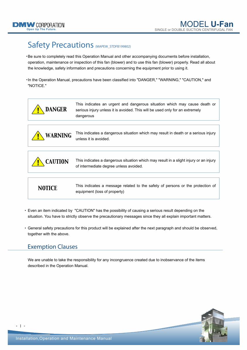
! DANGER This indicates an urgent and dangerous situation which may cause death or
serious injury unless it is avoided. This will be used only for an extremely
dangerous
! WARNING This indicates a dangerous situation which may result in death or a serious injury
unless it is avoided.
! CAUTION This indicates a dangerous situation which may result in a slight injury or an injury
of intermediate degree unless avoided.
NOTICE This indicates a message related to the safety of persons or the protection of
equipment (loss of property)
Safety Precautions (MAPEW_STDFB199802)
Ⅰ
Be sure to completely read this Operation Manual and other accompanying documents before installation,
operation, maintenance or inspection of this fan (blower) and to use this fan (blower) properly. Read all about
the knowledge, safety information and precautions concerning the equipment prior to using it.
In the Operation Manual, precautions have been classified into "DANGER," "WARNING," "CAUTION," and
"NOTICE."
•
•
Exemption Clauses
MODEL U-Fan SINGLE or DOUBLE SUCTION CENTRIFUGAL FAN
- -
Installation,Operation and Maintenance Manual
Ⅱ
The precautions to be strictly observed when operating the fan (blower) are listed below. These precautions
must be strictly observed.
1.
Perform the following pre-starting checks:
Check that all safety guards are mounted correctly and securely.
Check that all alarm contacts operate correctly under the previously set conditions.
Check that the gas detector operates correctly.
1)
a)
b)
c)
Keep the power of the gas detector turned on to perform checks during operation. 2)
Do not put hands or objects into the safety guards during operation. 3)
If the shaft seals are of the type that require purging, continually provide nitrogen gas or air purging. 4)
For a fan (blower) that handles hot gas, keep hands away from the exposed parts of the operating during or
immediately after operation.
5)
When checking the fan (blower) in their stopped condition, strictly observe the following safety precautions: 2.
Before starting checks, make sure that the motor is turned off. Also, provide appropriate marking or labeling so
that the motor is inadvertently turned on.
1)
If the fan (blower) handles gas other than air, check for safety by performing inert gas replacements before
disassembling the casing.
2)
If the fan (blower) handles potentially flammable gas, do not use fire nearby. If it becomes absolutely necessary
to use fire, check for gas and see that the intended work can be performed safely.
3)
Do not modify the fan (blower) itself and do not disturb the preset conditions of related units.
Please contact us if modification associated with changes in operating specifications is required.
3.
If the warning labels attached to the product become detached or damaged, reorder them from our Head Office
sales department.
4.
Safety Precautions (MAPEW_STDFB199802)
General Safety Precautions
MODEL U-Fan SINGLE or DOUBLE SUCTION CENTRIFUGAL FAN
- -
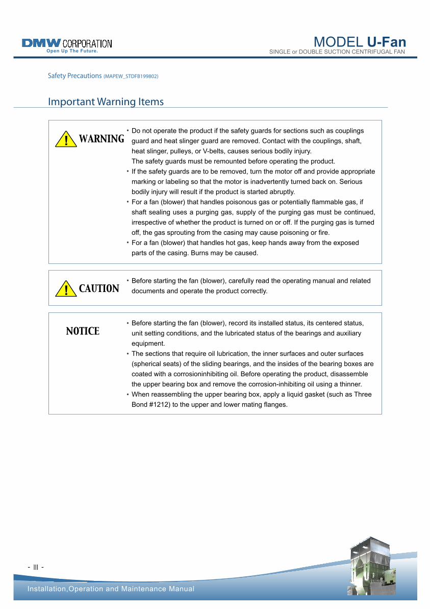
! WARNING Do not operate the product if the safety guards for sections such as couplings
guard and heat slinger guard are removed. Contact with the couplings, shaft,
heat slinger, pulleys, or V-belts, causes serious bodily injury.
The safety guards must be remounted before operating the product.
If the safety guards are to be removed, turn the motor off and provide appropriate
marking or labeling so that the motor is inadvertently turned back on. Serious
bodily injury will result if the product is started abruptly.
For a fan (blower) that handles poisonous gas or potentially flammable gas, if
shaft sealing uses a purging gas, supply of the purging gas must be continued,
irrespective of whether the product is turned on or off. If the purging gas is turned
off, the gas sprouting from the casing may cause poisoning or fire.
For a fan (blower) that handles hot gas, keep hands away from the exposed
parts of the casing. Burns may be caused.
! CAUTION Before starting the fan (blower), carefully read the operating manual and related
documents and operate the product correctly.
NOTICE Before starting the fan (blower), record its installed status, its centered status,
unit setting conditions, and the lubricated status of the bearings and auxiliary
equipment.
The sections that require oil lubrication, the inner surfaces and outer surfaces
(spherical seats) of the sliding bearings, and the insides of the bearing boxes are
coated with a corrosioninhibiting oil. Before operating the product, disassemble
the upper bearing box and remove the corrosion-inhibiting oil using a thinner.
When reassembling the upper bearing box, apply a liquid gasket (such as Three
Bond #1212) to the upper and lower mating flanges.
Installation,Operation and Maintenance Manual
Ⅲ
Safety Precautions (MAPEW_STDFB199802)
Important Warning Items
•
•
•
•
•
•
•
•
MODEL U-Fan SINGLE or DOUBLE SUCTION CENTRIFUGAL FAN
- -
Installation,Operation and Maintenance Manual
Ⅳ
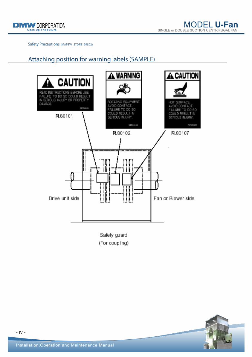
Attaching position for warning labels (SAMPLE)
Safety Precautions (MAPEW_STDFB199802)
- -
MODEL U-Fan SINGLE or DOUBLE SUCTION CENTRIFUGAL FAN
Installation,Operation and Maintenance Manual
Chapter 1 Introduction (MAPEP_STDFB199802)
1
This manual is intended for the user of the fan (blower) to thoroughly understand their correct usage. 1)
After in-factory stringent product inspection, the fan (blower) has undergone our withstand pressure tests and
operational tests with in-factory testing equipment in accordance with JIS-B8330 (fan), JIS-B8340(blower) to
verify that specifications on the operational status, performance, etc. of the product are satisfied and that the
required standards are passed.
2)
The fan (blower) must be correctly serviced and operated to provide their excellent performance.
Mis-handling causes trouble in addition to preventing satisfactory performance from being achievable.
Always operate the product within the limits laid down in this manual, and avoid applying an overload.
Also, perform correct maintenance and checks and undertake all possible preventive measures against
accidents.
3)
If an operational failure or other trouble occurs, please contact us giving the following information:
Information contained the specifications plate of the fan (blower) ; (that is, type, pressure, capacity,
speed, built, and serial number)
Information concerning the trouble (please give us the furthest possible detailed information about the status
existing before and after the trouble occurred)
See the end of this manual for the listing of contact addresses.
4)
a)
b)
- -
MODEL U-Fan SINGLE or DOUBLE SUCTION CENTRIFUGAL FAN
Chapter 2 Structure of Model DBSB Fan (MAPES_STDFDBSB199802)
Installation,Operation and Maintenance Manual
2
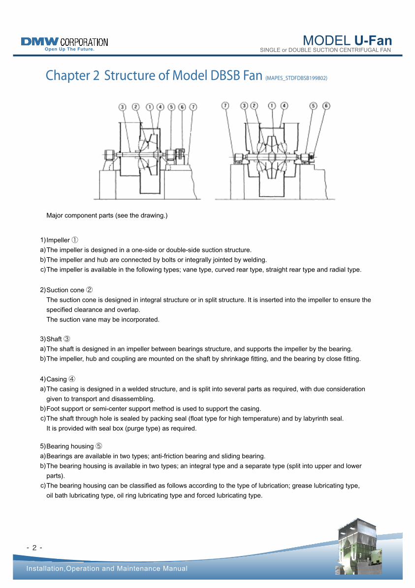
Major component parts (see the drawing.)
Impeller ① The impeller is designed in a one-side or double-side suction structure.
The impeller and hub are connected by bolts or integrally jointed by welding.
The impeller is available in the following types; vane type, curved rear type, straight rear type and radial type.
1)
a)
b)
c)
Suction cone ② The suction cone is designed in integral structure or in split structure. It is inserted into the impeller to ensure the
specified clearance and overlap.
The suction vane may be incorporated.
2)
Shaft ③ The shaft is designed in an impeller between bearings structure, and supports the impeller by the bearing.
The impeller, hub and coupling are mounted on the shaft by shrinkage fitting, and the bearing by close fitting.
3)
a)
b)
Casing ④ The casing is designed in a welded structure, and is split into several parts as required, with due consideration
given to transport and disassembling.
Foot support or semi-center support method is used to support the casing.
The shaft through hole is sealed by packing seal (float type for high temperature) and by labyrinth seal.
It is provided with seal box (purge type) as required.
4)
a)
b)
c)
Bearing housing ⑤ Bearings are available in two types; anti-friction bearing and sliding bearing.
The bearing housing is available in two types; an integral type and a separate type (split into upper and lower
parts).
The bearing housing can be classified as follows according to the type of lubrication; grease lubricating type,
oil bath lubricating type, oil ring lubricating type and forced lubricating type.
5)
a)
b)
c)
- -
MODEL U-Fan SINGLE or DOUBLE SUCTION CENTRIFUGAL FAN
Installation,Operation and Maintenance Manual
Chapter 2 Structure of Model DBSB Fan (MAPES_STDFDBSB199802)
3
Cooling is provided by water cooling, non-water cooling or forced air cooling.
In the case of grease lubrication, felt ring, oil bath and oil ring are used for shaft through hole sealing.
Labyrinth sealing is used in the case of forced lubrication.
d)
e)
Coupling ⑥ Flexible couplings are used.
The following types of couplings are mainly used:
JIS flange coupling
Gear coupling
Disk coupling
6)
a)
b)
① ② ③
Base ⑦ The base is available in the following types; independent bearing base, independent drive unit base and
common base.
The independent bearing base is designed in the one-step or two-step structure.
7)
a)
b)
- -
MODEL U-Fan SINGLE or DOUBLE SUCTION CENTRIFUGAL FAN
Chapter 3 Disassembly and Assembly (MAPED_STDFDBSBBJ199802)
Installation,Operation and Maintenance Manual
! WARNING If the fan (blower) handles gas other than air, perform inert gas replacements and
see that the replacements are completed.
•
! WARNING Before starting disassembly, make sure that if the product is driven by motor, the
power of the motor is turned off.
When lifting the product, check its weight and the angle of lifting.
Check your footing for safety.
•
•
•
• ! CAUTION Ask us or a specialized service company for part replacement or repair. Wrong
maintenance may cause trouble or accidents.
• ! CAUTION Thoroughly understand the construction of the fan (blower) and use the correct
procedures
3.1 Disassembly and maintenance
1.1 Checking before starting the work 3.
1.2 Confirmation before disassembly 3.
4
Prepare the required disassembly tools and measuring tools.
Confirm the disassembly and assembly procedure.
Prepare the required replacement parts.
Prepare the small parts kit, rotating member support base, and bearing protectors such as rags and vinyl.
1)
2)
3)
4)
During operation (Record the operating conditions before disassembly.)
Measure and record the bearing vibration before disassembly.
Check if gas leaks from the casing.
Check the bearing for noise.
Check the casing internal noise.
1)
a)
b)
c)
d)
- -
MODEL U-Fan SINGLE or DOUBLE SUCTION CENTRIFUGAL FAN
Installation,Operation and Maintenance Manual
Chapter 3 Disassembly and Assembly (MAPED_STDFDBSBBJ199802)
1.3 Disassembly procedure 3.
5
When stop
Visually observe the appearance.
Record the coupling misalignment.
Check if there is any contact between the rotating member and stationary member.
Check if lubricating oil is oozing or not. Also check the bearing housing for contamination.
Make sure that anchor bolt (installation bolt) is tightened.
When gas other than air must be handled, make sure that gas replacement must have been completed.
Check the parts for separation identification and matching marks.
When disassembly is required due to accident, take a photograph of internal conditions.
2)
a)
b)
c)
d)
e)
f)
g)
h)
Remove the safety guard.
Remove the connection link between the damper or suction vane proper and operating equipment.
Remove the expansion joint of the suction and discharge cones, or the connection with the silencer, and the
piezometer.
1)
2)
3)
Disconnect the damper or suction vane proper from the casing. 4)
Disengage the coupling between the fan and drive unit.
For JIS flange type coupling
Loosen the nut of the coupling bolt and remove all the coupling bolts.
For gear coupling
Loosen the nut of the installation bolt and remove all the installation bolts. Care should be taken not to damage
the O-ring.
For disk coupling
Loosen the nut of the spacer installation bolt and remove all the installation bolts. Then draw out the element.
5)
a)
b)
c)
Disconnect the suction cone installation bolt, and remove the suction cone. 6)
For the split type casing, remove the installation bolt of the flange by lifting the upper casing in the vertical direction.
(Use the external drawing to confirm the height required for disassembly.)
7)
MODEL U-Fan SINGLE or DOUBLE SUCTION CENTRIFUGAL FAN
- -
Installation,Operation and Maintenance Manual
Chapter 3 Disassembly and Assembly (MAPED_STDFDBSBBJ199802)
6
In this case, heat the periphery of the hub in a short time.
If heated for a long time, heat will be conveyed to the shaft, and clearance may
not occur. The appropriate heating temperature will be 100 degrees Celsius.
NOTICE •
•
Apply cloth so that shaft will not be damaged, and apply the wire protected with rubber.
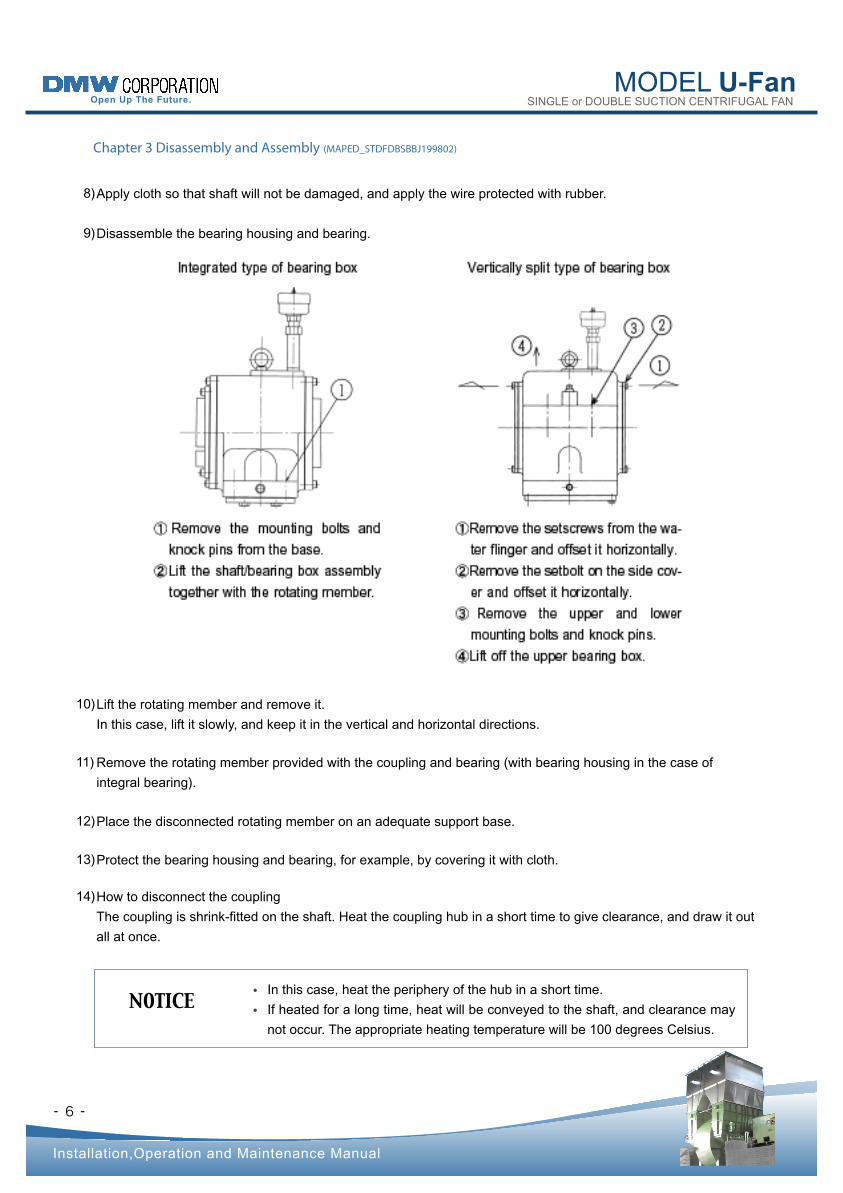
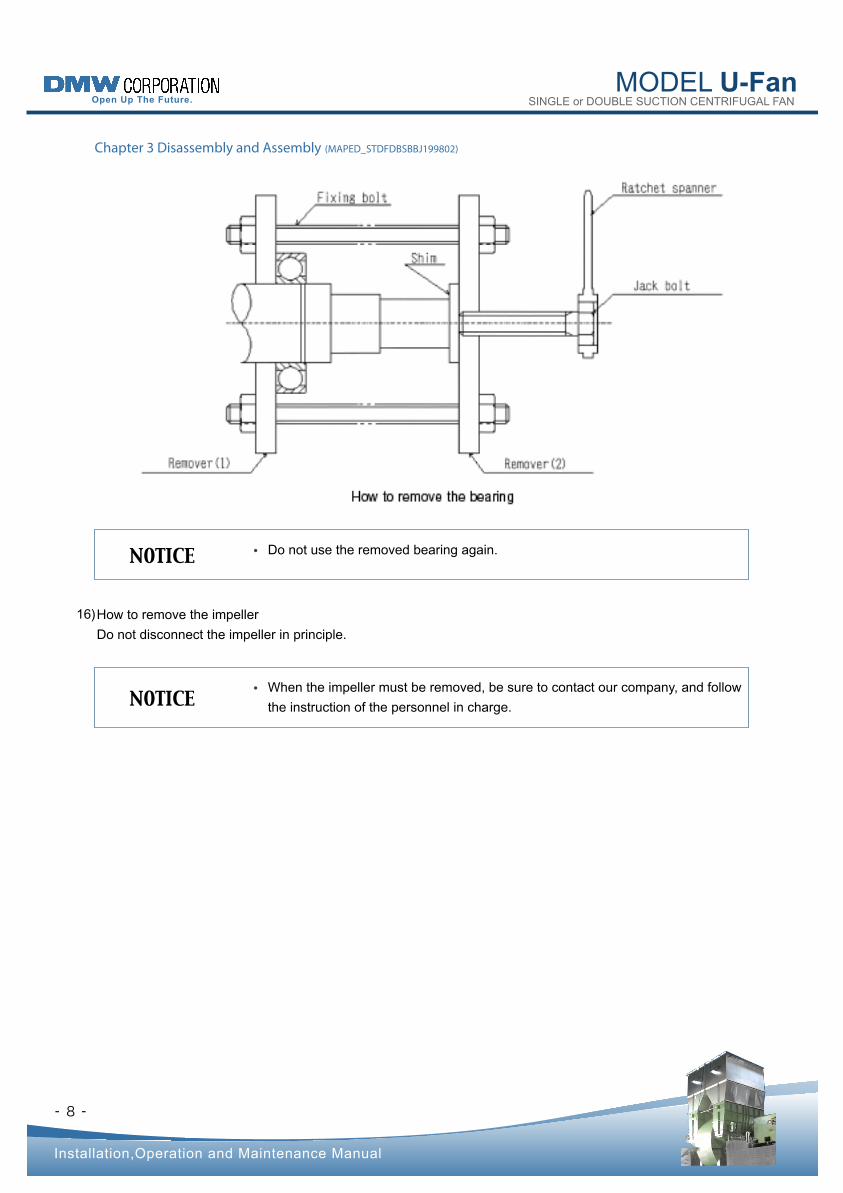
Disassemble the bearing housing and bearing.
8)
9)
Lift the rotating member and remove it.
In this case, lift it slowly, and keep it in the vertical and horizontal directions.
10)
Remove the rotating member provided with the coupling and bearing (with bearing housing in the case of
integral bearing).
11)
Place the disconnected rotating member on an adequate support base. 12)
Protect the bearing housing and bearing, for example, by covering it with cloth. 13)
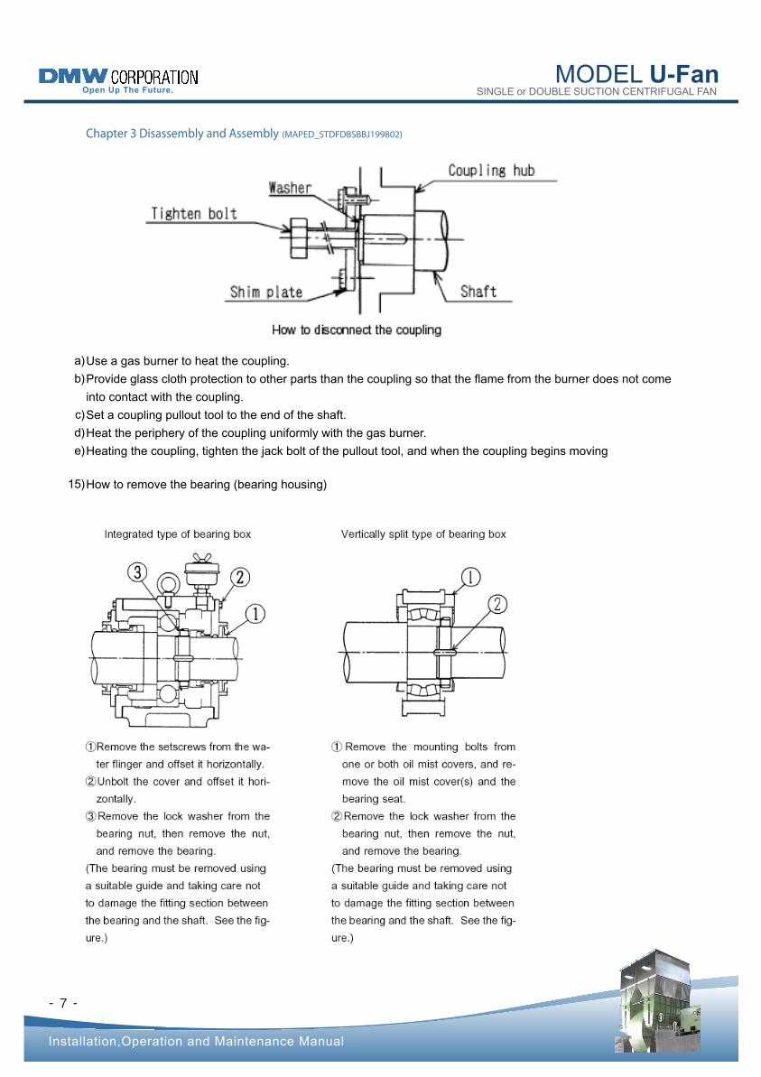
How to disconnect the coupling
The coupling is shrink-fitted on the shaft. Heat the coupling hub in a short time to give clearance, and draw it out
all at once.
14)
MODEL U-Fan SINGLE or DOUBLE SUCTION CENTRIFUGAL FAN
- -
Installation,Operation and Maintenance Manual
Chapter 3 Disassembly and Assembly (MAPED_STDFDBSBBJ199802)
7
Use a gas burner to heat the coupling.
Provide glass cloth protection to other parts than the coupling so that the flame from the burner does not come
into contact with the coupling.
Set a coupling pullout tool to the end of the shaft.
Heat the periphery of the coupling uniformly with the gas burner.
Heating the coupling, tighten the jack bolt of the pullout tool, and when the coupling begins moving
a)
b)
c)
d)
e)
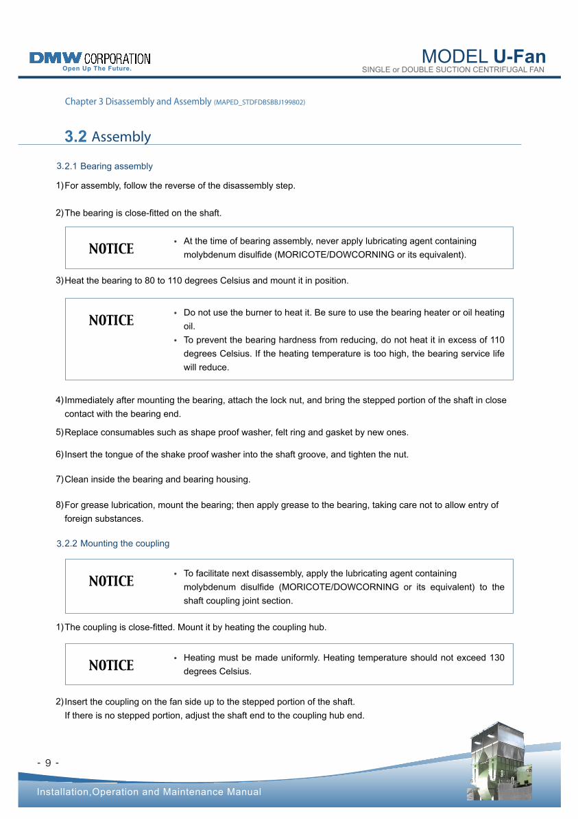
How to remove the bearing (bearing housing) 15)
MODEL U-Fan SINGLE or DOUBLE SUCTION CENTRIFUGAL FAN
- -
Installation,Operation and Maintenance Manual
Chapter 3 Disassembly and Assembly (MAPED_STDFDBSBBJ199802)
8
Do not use the removed bearing again.NOTICE •
When the impeller must be removed, be sure to contact our company, and follow
the instruction of the personnel in charge.NOTICE •
How to remove the impeller
Do not disconnect the impeller in principle.
16)
MODEL U-Fan SINGLE or DOUBLE SUCTION CENTRIFUGAL FAN
- -
Installation,Operation and Maintenance Manual
3.2 Assembly
Chapter 3 Disassembly and Assembly (MAPED_STDFDBSBBJ199802)
2.1 Bearing assembly 3.
2.2 Mounting the coupling 3.
9
At the time of bearing assembly, never apply lubricating agent containing
molybdenum disulfide (MORICOTE/DOWCORNING or its equivalent).NOTICE •
Do not use the burner to heat it. Be sure to use the bearing heater or oil heating
oil.
To prevent the bearing hardness from reducing, do not heat it in excess of 110
degrees Celsius. If the heating temperature is too high, the bearing service life
will reduce.
NOTICE •
•
To facilitate next disassembly, apply the lubricating agent containing
molybdenum disulfide (MORICOTE/DOWCORNING or its equivalent) to the
shaft coupling joint section.
NOTICE •
Heating must be made uniformly. Heating temperature should not exceed 130
degrees Celsius.NOTICE •
Heat the bearing to 80 to 110 degrees Celsius and mount it in position. 3)
Immediately after mounting the bearing, attach the lock nut, and bring the stepped portion of the shaft in close
contact with the bearing end.
4)
Replace consumables such as shape proof washer, felt ring and gasket by new ones. 5)
Insert the tongue of the shake proof washer into the shaft groove, and tighten the nut. 6)
Clean inside the bearing and bearing housing. 7)
For grease lubrication, mount the bearing; then apply grease to the bearing, taking care not to allow entry of
foreign substances.
8)
The coupling is close-fitted. Mount it by heating the coupling hub. 1)
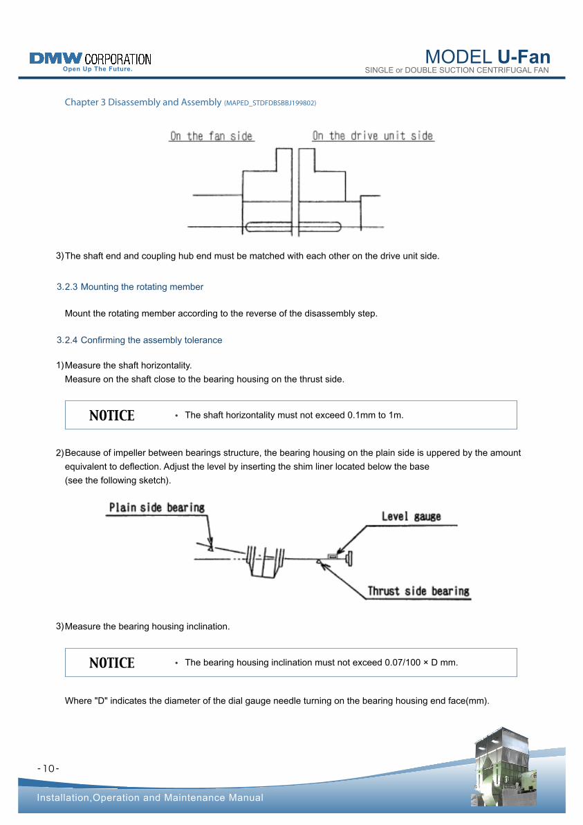
Insert the coupling on the fan side up to the stepped portion of the shaft.
If there is no stepped portion, adjust the shaft end to the coupling hub end.
2)
For assembly, follow the reverse of the disassembly step.
The bearing is close-fitted on the shaft.
1)
2)
MODEL U-Fan SINGLE or DOUBLE SUCTION CENTRIFUGAL FAN
- -
Installation,Operation and Maintenance Manual
Chapter 3 Disassembly and Assembly (MAPED_STDFDBSBBJ199802)
2.3 Mounting the rotating member 3.
2.4 Confirming the assembly tolerance 3.
10
The shaft horizontality must not exceed 0.1mm to 1m.NOTICE •
The bearing housing inclination must not exceed 0.07/100 × D mm.NOTICE •
The shaft end and coupling hub end must be matched with each other on the drive unit side. 3)
Mount the rotating member according to the reverse of the disassembly step.
Measure the shaft horizontality.
Measure on the shaft close to the bearing housing on the thrust side.
Where "D" indicates the diameter of the dial gauge needle turning on the bearing housing end face(mm).
1)
Because of impeller between bearings structure, the bearing housing on the plain side is uppered by the amount
equivalent to deflection. Adjust the level by inserting the shim liner located below the base
(see the following sketch).
2)
Measure the bearing housing inclination. 3)
- -
MODEL U-Fan SINGLE or DOUBLE SUCTION CENTRIFUGAL FAN
Installation,Operation and Maintenance Manual
Chapter 3 Disassembly and Assembly (MAPED_STDFDBSBBJ199802)
2.5 Assembling the casing 3.
11
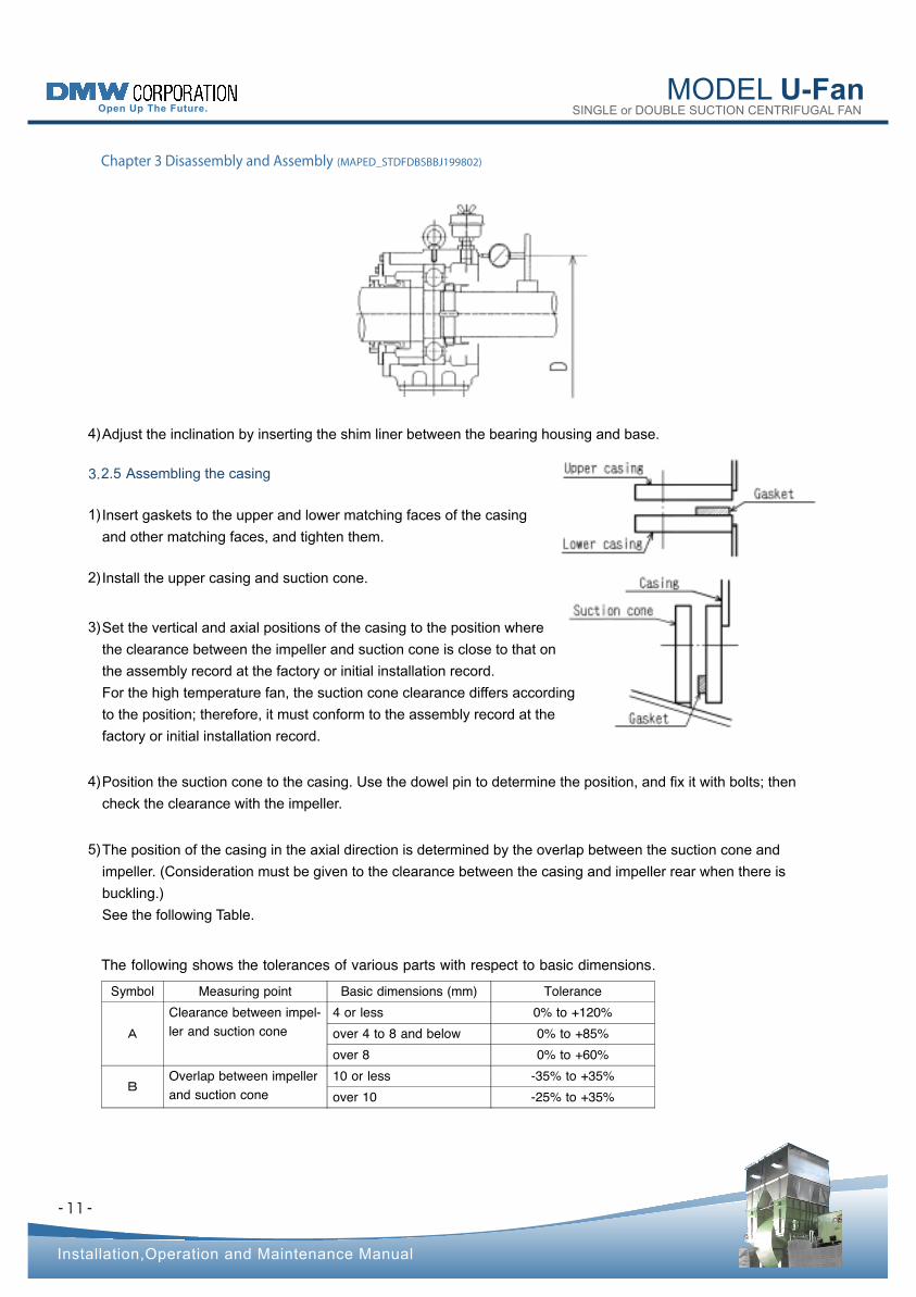
Adjust the inclination by inserting the shim liner between the bearing housing and base. 4)
Insert gaskets to the upper and lower matching faces of the casing
and other matching faces, and tighten them.
1)
Install the upper casing and suction cone. 2)
3)
Position the suction cone to the casing. Use the dowel pin to determine the position, and fix it with bolts; then
check the clearance with the impeller.
4)
The position of the casing in the axial direction is determined by the overlap between the suction cone and
impeller. (Consideration must be given to the clearance between the casing and impeller rear when there is
buckling.)
See the following Table.
5)
Set the vertical and axial positions of the casing to the position where
the clearance between the impeller and suction cone is close to that on
the assembly record at the factory or initial installation record.
For the high temperature fan, the suction cone clearance differs according
to the position; therefore, it must conform to the assembly record at the
factory or initial installation record.
Symbol Measuring point Basic dimensions (mm) Tolerance
A
Clearance between impel- ler and suction cone
4 or less 0% to +120% over 4 to 8 and below 0% to +85% over 8 0% to +60%
BOverlap between impeller and suction cone
10 or less -35% to +35% over 10 -25% to +35%
The following shows the tolerances of various parts with respect to basic dimensions .
- -
MODEL U-Fan SINGLE or DOUBLE SUCTION CENTRIFUGAL FAN
Installation,Operation and Maintenance Manual
2.6 Alignment adjustment 3.
2.7 Accessory assembly 3.
Chapter 3 Disassembly and Assembly (MAPED_STDFDBSBBJ199802)
12
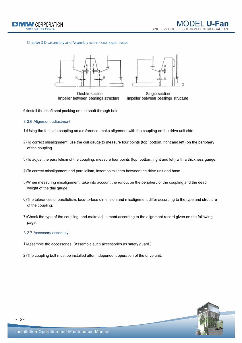
Install the shaft seal packing on the shaft through hole. 6)
Using the fan side coupling as a reference, make alignment with the coupling on the drive unit side.
To correct misalignment, use the dial gauge to measure four points (top, bottom, right and left) on the periphery
of the coupling.
To adjust the parallelism of the coupling, measure four points (top, bottom, right and left) with a thickness gauge.
To correct misalignment and parallelism, insert shim liners between the drive unit and base.
When measuring misalignment, take into account the runout on the periphery of the coupling and the dead
weight of the dial gauge.
The tolerances of parallelism, face-to-face dimension and misalignment differ according to the type and structure
of the coupling.
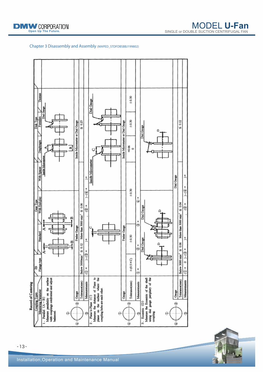
Check the type of the coupling, and make adjustment according to the alignment record given on the following
page.
1)
2)
3)
4)
5)
6)
7)
Assemble the accessories. (Assemble such accessories as safety guard.)
The coupling bolt must be installed after independent operation of the drive unit.
1)
2)
- -
MODEL U-Fan SINGLE or DOUBLE SUCTION CENTRIFUGAL FAN
Installation,Operation and Maintenance Manual
Chapter 3 Disassembly and Assembly (MAPED_STDFDBSBBJ199802)
13
- -
MODEL U-Fan SINGLE or DOUBLE SUCTION CENTRIFUGAL FAN
Chapter 4 Operation (MAPEO_STDF199802)
Installation,Operation and Maintenance Manual
4.1 Operating Notes
14
Do not to operate the fan more than three minutes when it blows inadequately,
otherwise the inside temperature of the fan rises, and it shall cause mal-function
and damages at the fan.
Do not operate the fan (blower) for more than three minutes in its surging region.
Increases in vibration cause trouble.
Operate the fan (blower) at loads exceeding the rated output of the driving motor.
Continued overloading causes trouble.
NOTICE •
•
•
It is desirable that the fan (blower) be operated in the vicinity of its design flow rate. It may however become
absolutely necessary to operate the fan (blower) at low flow rate. If this is the case, the characteristics of the fan
(blower) must be thoroughly understood before operating it.
If the fan (blower) handles a hot gas or a gas significantly differing from air in terms of density
When the fan (blower) is started using normal-temperature air, overloaded operation may continue until the
required temperature or density has been reached. Therefore, reduce the degree of opening of the dampers or
suction vanes or operate the fan (blower) in the bypass operation, blow-off operation, or deceleration operation.
■
If the fan (blower) is to be operated at low flow rate
If the fan (blower) is to be operated at low flow rate, surging or rotational stalling may occur and increase
the vibration of the casing, bearings, or ducting, or the low-frequency noise level. Extended operation under
these states causes damage to the casing, bearings, or ducting, cracking of the foundation concrete, or other
trouble. Therefore, increase the flow rate by either increasing the degree of opening of the dampers or suction
vanes or combining air restriction with bypass operation or blowoff operation.
■
- -
MODEL U-Fan SINGLE or DOUBLE SUCTION CENTRIFUGAL FAN
Installation,Operation and Maintenance Manual
Chapter 4 Operation (MAPEO_STDF199802)
4.2 Items to be con�rmed before operation
15
Check to see that oil pipe, shaft sealing pipe and coolant pipe are flushed.
Check the casing interior, air suction cone, suction/discharge pipe connections
and the area surrounding the fan. Make sure that parts, tools and other remnants
are not left behind.
NOTICE •
•
Loosen the shipping bolts for transport and installation.NOTICE •
Start independent operation of the drive unit, and make sure that there is no problem in rotational direction or
vibration.
Before starting the operation, check the following when the equipment is started for the first time after installing
the fan, after a long-time disuse or after disassembly and maintenance.
1)
Turn power off after checking.
Reconnect the coupling between the driving motor and the fan (blower).
a)
b)
Check the fan operation sequence. 2)
Assembly
Make sure that all bolts are tightened firmly.
Make sure that coupling bolts are tightened firmly.
Check that there are proper clearances between the rotating member and stationary member
(suction cone and impeller, impeller and casing, and shaft and casing shaft through hole).
3)
a)
b)
c)
Make sure that the safety guard is correctly installed. 4)
When the suction and discharge cones are provided with expansion joints, they must be installed properly due
consideration given to thermal expansion.
5)
! WARNING If the fan (blower) is driven by motor, the terminal box cover must be kept mounted
to avoid the danger of electric shock.
•
! WARNING If the fan (blower) is driven by motor, check that the power of the motor is turned
off.
•
MODEL U-Fan SINGLE or DOUBLE SUCTION CENTRIFUGAL FAN
- -
Installation,Operation and Maintenance Manual
Chapter 4 Operation (MAPEO_STDF199802)
4.3 Preparation for startup
16
To check setting parameters at safety devices in order to avoid any mal-faction
which shall cause any damage at bearings.NOTICE •
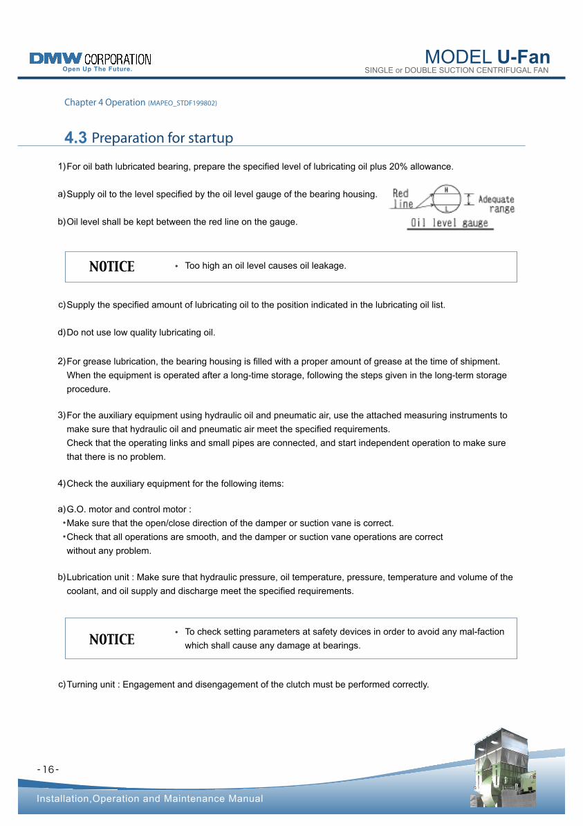
Too high an oil level causes oil leakage.NOTICE •
Check the auxiliary equipment for the following items: 4)
For oil bath lubricated bearing, prepare the specified level of lubricating oil plus 20% allowance.
Supply oil to the level specified by the oil level gauge of the bearing housing.
Oil level shall be kept between the red line on the gauge.
1)
a)
b)
Supply the specified amount of lubricating oil to the position indicated in the lubricating oil list. c)
Do not use low quality lubricating oil. d)
For grease lubrication, the bearing housing is filled with a proper amount of grease at the time of shipment.
When the equipment is operated after a long-time storage, following the steps given in the long-term storage
procedure.
2)
For the auxiliary equipment using hydraulic oil and pneumatic air, use the attached measuring instruments to
make sure that hydraulic oil and pneumatic air meet the specified requirements.
Check that the operating links and small pipes are connected, and start independent operation to make sure
that there is no problem.
3)
G.O. motor and control motor :
Make sure that the open/close direction of the damper or suction vane is correct.
Check that all operations are smooth, and the damper or suction vane operations are correct
without any problem.
a)
•
•
Lubrication unit : Make sure that hydraulic pressure, oil temperature, pressure, temperature and volume of the
coolant, and oil supply and discharge meet the specified requirements.
b)
Turning unit : Engagement and disengagement of the clutch must be performed correctly. c)
MODEL U-Fan SINGLE or DOUBLE SUCTION CENTRIFUGAL FAN
- -
Installation,Operation and Maintenance Manual
Chapter 4 Operation (MAPEO_STDF199802)
17
If any abnormality occurs, examine and remove the cause of the abnormality.
Continued operation of abnormal fan (blower) causes trouble.NOTICE •
Speed change gear : The hydraulic multiple disk clutch type speed change gear and fluid coupling
must permit specified speed control. Preparation for startup must have been completed.
d)
Shaft seal (carbon ring seal, mechanical seal, etc.) : The specified volume and pressure of seal
gas must be ensured.
e)
Feed the specified coolant when a water-cooled bearing housing is used. Check the type of the bearing housing
according to the appended Installation Drawing (external view) and Bearing unit Drawing.
5)
In principle, keep the suction damper (or suction vane) or discharge damper fully closed. 6)
Make sure that preparation has been completed for the operation of the main power supply, auxiliary equipment
power circuit, valve of the main pipe and auxiliary equipment.
7)
Feed the drive unit in the jog mode, and check for rotational direction, internal contact and abnormal noise. 8)
! WARNING Insufficiencies in the amount and pressure of sealing gas cause the internal gas
to leak from the fan (blower) and create a dangerous situation in the presence of
poisonous gases or potentially flammable gases.
•
MODEL U-Fan SINGLE or DOUBLE SUCTION CENTRIFUGAL FAN
- -
Installation,Operation and Maintenance Manual
4.4 Startup
Chapter 4 Operation (MAPEO_STDF199802)
18
To stop the machine immediately and start investigation of causes when any
abnormal condition appears.NOTICE •
Do not increase the temperature of gas rapidly when it reaches over 100℃. The
ratio of the rise in the temperature of gas shall be 50℃ per hour (not exceed
100℃ per hour).
Abrupt increases in temperature can cause increased vibration or collision
accidents since the differences in the degree of thermal expansion between
rotating parts result in imbalance.
NOTICE •
•
Star t up the equipment while checking plant safety. 1)
Operate necessary auxiliary equipment and make sure that the starting conditions for the fan (blower) are
established.
2)
Star t the fan (blower). 3)
Simultaneously with startup, check for internal contact, abnormal noise and vibration. 4)
In the case of the sliding bearing, check the oil ring for rotation.
(Remove the oil cover and check it by visual observation.)
If rotation is not smooth or horizontal unusual vibration is observed, these imply that the oil ring is deformed or
that the oil ring or the wall of the bearing groove has rotation- obstructing flaws or is not smooth or flat.
Therefore, check for these defects and if any is found, remove the cause(s).
■
After the specified speed has been reached, gradually open the suction damper (or suction vane) or discharge
damper.
In this case, ensure that the surge area will be passed through in the shortest possible time.
The current value will undergo drastic change in the surge area. Observing the ammeter, open the suction
damper (or suction vane) or discharge damper quickly.
5)
After startup, check for bearing vibration, bearing temperature and noise every 5 to 10 minutes until bearing
temperature is stabilized. Make sure that there is no abnormal temperature rise.
6)
For a fan (blower) that handles a hot gas, if the starting temperature of the fan (blower) is lower than the gas
temperature, increased shaft output may cause overloaded operation. Reduce the degree of opening of the
dampers or suction vanes to operate the fan (blower) in that case. Operation with reduced damper or suction
vane angle, however, may cause surging or rotational stalling. In that case, either combine air restriction with
bypass operation or blow-off operation or reduce the revolutions.
■
! WARNING During operation, keep hands away from all rotating parts such as the shaft,
heat slinger, coupling, and V-belts. Contact causes serious injury.
•
MODEL U-Fan SINGLE or DOUBLE SUCTION CENTRIFUGAL FAN
- -
Installation,Operation and Maintenance Manual
Chapter 4 Operation (MAPEO_STDF199802)
19
The improper heat expansion (restriction of heat expansion) at shafts and
casings shall make them touch and grind, and it may cause unusual vibration,
improper temperature increase at bearings, etc.
When this phenomenon observed, to stop increasing the gas temperature, and
to check any parts fused, except pre-fixed sections.
NOTICE •
Notes on turning
If the opening of the suction damper (or suction vane) or discharge damper is
excessive during turning, rotation may be reversed by flow of air. Gradually open
the damper or suction vane so that rotation will not be reversed.
NOTICE •
To make "Turning" before re-start of fan(blower) absolutely because it becomes
to cause of vibration increase, bearing damage, foundation damage & contact
accident if operation continues at condition of shaft bending or un-balance.
To ensure that temperature of various parts of the rotating member is kept almost
constant, slightly open the suction damper (suction vane) or discharge damper.
Feed high temperature gas and turn the rotating member; then start the
operation.
NOTICE •
•
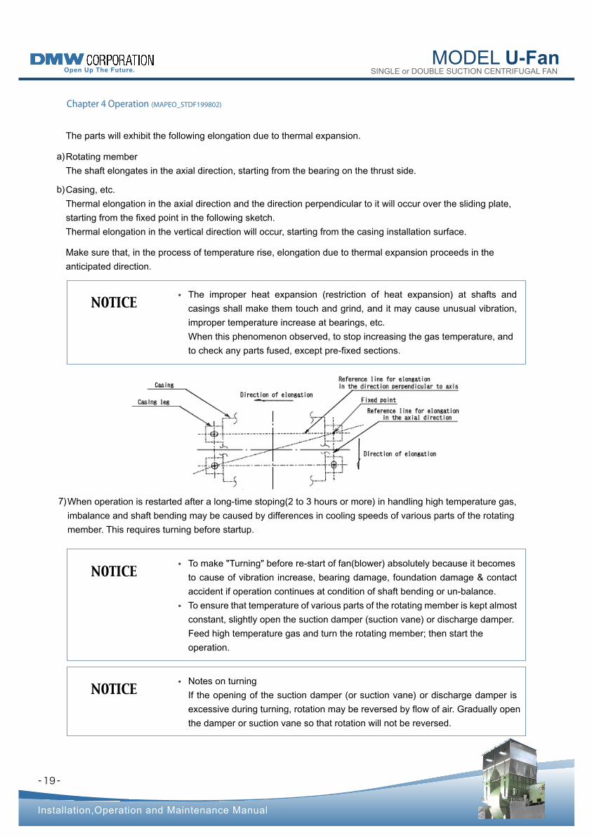
Rotating member
The shaft elongates in the axial direction, starting from the bearing on the thrust side.
a)
Casing, etc.
Thermal elongation in the axial direction and the direction perpendicular to it will occur over the sliding plate,
starting from the fixed point in the following sketch.
Thermal elongation in the vertical direction will occur, starting from the casing installation surface.
b)
Make sure that, in the process of temperature rise, elongation due to thermal expansion proceeds in the
anticipated direction.
When operation is restarted after a long-time stoping(2 to 3 hours or more) in handling high temperature gas,
imbalance and shaft bending may be caused by differences in cooling speeds of various parts of the rotating
member. This requires turning before startup.
7)
The parts will exhibit the following elongation due to thermal expansion.
MODEL U-Fan SINGLE or DOUBLE SUCTION CENTRIFUGAL FAN
- -
Installation,Operation and Maintenance Manual
Chapter 4 Operation (MAPEO_STDF199802)
Turning procedure
20
Make 1 + 1/4 rotations at an interval of 10 minutes manually (using the coupling part, etc.).
Make this adjustment until misalignment on the periphery of the coupling on the fan side is reduced below
1/10mm in terms of the reading of the dial gauge.
1)
Turning motor operate it for about 10 minutes when the turning device is used. 2)
- -
MODEL U-Fan SINGLE or DOUBLE SUCTION CENTRIFUGAL FAN
Installation,Operation and Maintenance Manual
4.5 Notes for operationNotes
Chapter 4 Operation (MAPEO_STDF199802)
21
It is recommended to record the pressure, air volume, current value, bearing temperature, bearing vibration,
etc. at specified intervals.
1)
During operation, check around the fan on a periodic basis. According to the appended "Check
List during Operation", carry out inspection, measurement and record of various parts. If the results are out of
the specified range, make adjustment according to "Chapter 5. Maintenance and Inspection".
2)
If any problem has been found out during the operation, it is necessary to take measures to prevent a trouble in
advance. After stopping the fan or conducting more intensive supervision, find out the cause of the problem.
3)
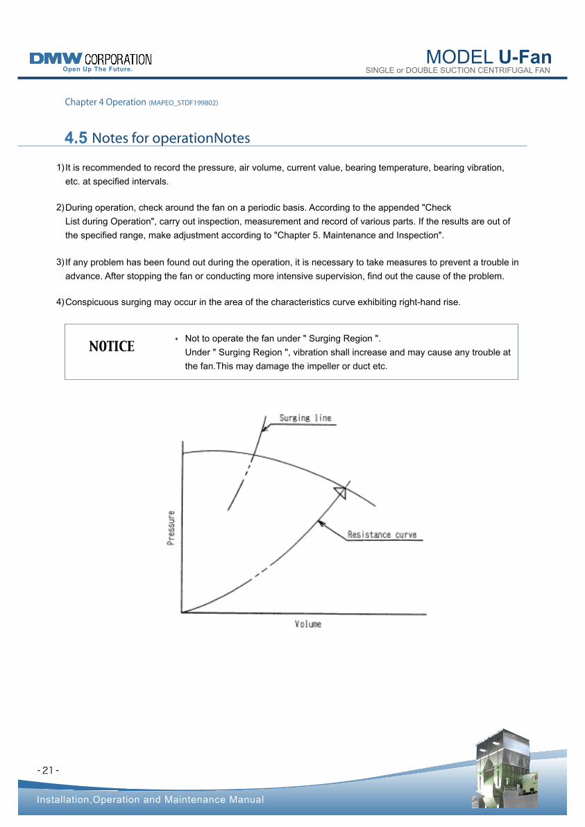
Conspicuous surging may occur in the area of the characteristics curve exhibiting right-hand rise. 4)
Not to operate the fan under " Surging Region ".
Under " Surging Region ", vibration shall increase and may cause any trouble at
the fan.This may damage the impeller or duct etc.
NOTICE •
- -
MODEL U-Fan SINGLE or DOUBLE SUCTION CENTRIFUGAL FAN
Installation,Operation and Maintenance Manual
4.6 Stop
Chapter 4 Operation (MAPEO_STDF199802)
22
For normal stop, gradually close the suction damper (or suction vane) or discharge damper from the fully closed
state, thereby preventing reverse flow of gas. Then stop the drive unit.
If coolant is likely to freeze, keep water warm even after stopping, or remove water completely.
1)
2)
To carry out emergency stop in the event of an accident, stop the drive unit and
completely close the suction damper (or suction vane) or discharge damper at
the same time.
NOTICE •
! WARNING To ensure safety, do not remove the safety guard until the fan (blower) is
stopped completely.
•
- -
MODEL U-Fan SINGLE or DOUBLE SUCTION CENTRIFUGAL FAN
Chapter 5 Maintenance and Inspection (MAPEM_STDF199802)
Installation,Operation and Maintenance Manual
5.1 Storage and Curings
23
Remove rust and clean the equipment on a periodic basis. Put the cover on it to ensure that dust will not enter. 1)
Turn the rotating member on a periodic basis (about once a month) to prevent the bearing from becoming rusty,
or from sticking due to dust.
(If there is a turning device , operate it on a periodic basis.)
2)
Lock the handle to prevent the main valve from opening or closing. 3)
If long-term storage is specified, follow the instruction given in the separate "Long-term Storage Procedure". 4)
- -
MODEL U-Fan SINGLE or DOUBLE SUCTION CENTRIFUGAL FAN
Installation,Operation and Maintenance Manual
Chapter 5 Maintenance and Inspection (MAPEM_STDF199802)
5.2 Inspection
24
Vibration tolerance
See the appended "Bearing Vibration Evaluation Criteria".
1)
Bearing temperature tolerance
See the appended "Check List during Operation".
2)
Current value (when the motor is used)
Keep the current value below the rated current value of the motor.
3)
Consumable parts
Ball (rolling) bearing: Spring washer and liquid packing (Three Bond #1212)
Grease lubrication: Felt ring
Oil bath lubrication: Gaskets
Sliding bearing:
Gaskets, liquid packing (Three Bond #1212) and felt ring (if used)
Coupling
JIS flange type: Rubber ring
Gear type: O-rings
Disc type (FORMFLEX): Nylon nut for coupling bolt
1)
a)
•
•
b)
c)
•
•
•
Inspect the bearing temperature, bearing vibration, bearing noise, and internal noise of the casing.
Record the bearing temperature and bearing vibration at monthly intervals so that the results can be compared
with satisfactory conditions immediately after installation.
If bearing temperature and bearing vibration tend to increase, reduce the inspection intervals, thereby preventing
accident.
The frequency of fan (blower) overhauling depends on the type of gas to be handled, the operating conditions,
the type of material to be used, and other factors. However, overhauling the fan (blower) at least once for every
two years is recommended.
Conduct inspection according to 5.2.4 "Maintenance and Inspection Procedure" to be discussed later.
For disassembly and maintenance during inspection, see 3.1 "Disassembly and Maintenance" to be discussed
earlier.
The parts to be replaced during disassembly and maintenance are listed below.
! WARNING Be careful not to get your body caught at the rotating member of the fan (blower)
during operation.
•
2.2 Periodic inspection 5.
2.3 Replace the parts 5.
2.1 Daily inspection 5.
- -
MODEL U-Fan SINGLE or DOUBLE SUCTION CENTRIFUGAL FAN
Installation,Operation and Maintenance Manual
Chapter 5 Maintenance and Inspection (MAPEM_STDF199802)
25
Bearings
The recommended replacement criteria for the bearings are shown below.
2)
Ball rolling bearing: At least once for every two to three years, or 1/2 or less of the calculated life a)
Sliding bearing: At least 1.5 times the required clearance (refer to the Factory Inspection Record)
Clearance between shaft and bearing inside diameter
Clearance between bearing box spherical seat and bearing spherical outline
b)
•
•
Shaft-through packing: Glass cloth (usually to be 1 mm thick for a clearance of 2 mm or more)
Packings for casing and manhole: CR(Neolon) for up to 80 degrees C
Glass tape for above 80 degrees C
d)
e)
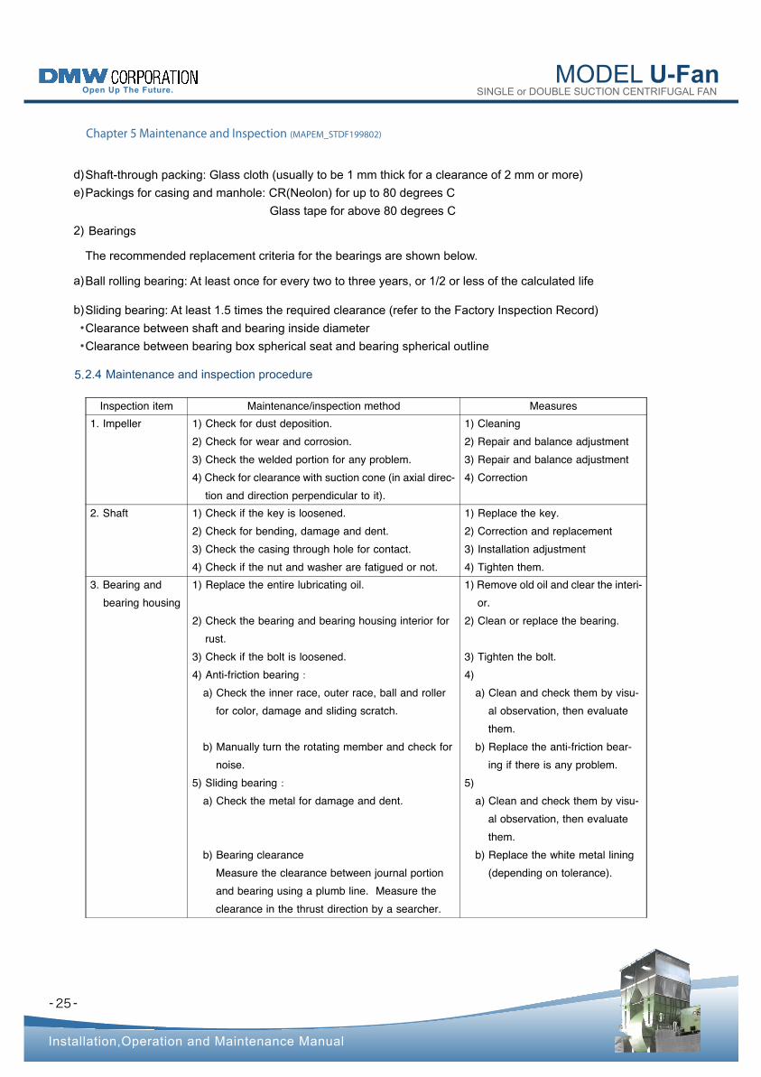
2.4 Maintenance and inspection procedure 5.
Inspection item Maintenance/inspection method Measures 1. Impeller 1) Check for dust deposition.
2) Check for wear and corrosion. 3) Check the welded portion for any problem. 4) Check for clearance with suction cone (in axial direc-
tion and direction perpendicular to it).
1) Cleaning 2) Repair and balance adjustment 3) Repair and balance adjustment 4) Correction
2. Shaft 1) Check if the key is loosened. 2) Check for bending, damage and dent. 3) Check the casing through hole for contact. 4) Check if the nut and washer are fatigued or not.
1) Replace the key. 2) Correction and replacement 3) Installation adjustment 4) Tighten them.
3. Bearing and bearing housing
1) Replace the entire lubricating oil.
2) Check the bearing and bearing housing interior for rust.
3) Check if the bolt is loosened. 4) Anti-friction bearing :
a) Check the inner race, outer race, ball and roller for color, damage and sliding scratch.
b) Manually turn the rotating member and check for noise.
5) Sliding bearing :a) Check the metal for damage and dent.
b) Bearing clearance Measure the clearance between journal portion and bearing using a plumb line. Measure the clearance in the thrust direction by a searcher.
1) Remove old oil and clear the interi- or.
2) Clean or replace the bearing.
3) Tighten the bolt. 4)
a) Clean and check them by visu- al observation, then evaluate them.
b) Replace the anti-friction bear- ing if there is any problem.
5) a) Clean and check them by visu-
al observation, then evaluate them.
b) Replace the white metal lining (depending on tolerance).
MODEL U-Fan SINGLE or DOUBLE SUCTION CENTRIFUGAL FAN
- -
Installation,Operation and Maintenance Manual
Chapter 5 Maintenance and Inspection (MAPEM_STDF199802)
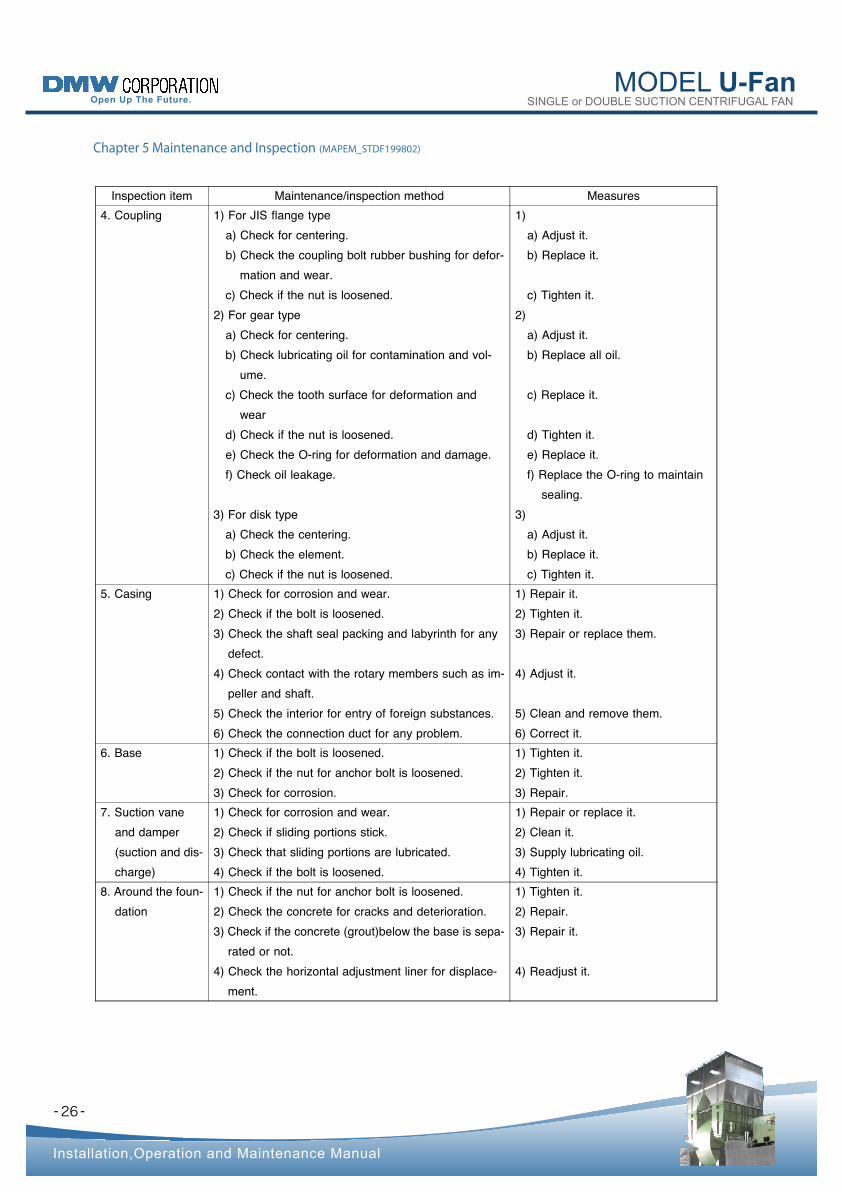
Inspection item Maintenance/inspection method Measures 4. Coupling 1) For JIS flange type
a) Check for centering. b) Check the coupling bolt rubber bushing for defor-
mation and wear. c) Check if the nut is loosened.
2) For gear type a) Check for centering. b) Check lubricating oil for contamination and vol-
ume. c) Check the tooth surface for deformation and
wear d) Check if the nut is loosened. e) Check the O-ring for deformation and damage. f) Check oil leakage.
3) For disk type a) Check the centering. b) Check the element. c) Check if the nut is loosened.
1) a) Adjust it. b) Replace it.
c) Tighten it. 2)
a) Adjust it. b) Replace all oil.
c) Replace it.
d) Tighten it. e) Replace it. f) Replace the O-ring to maintain
sealing. 3)
a) Adjust it. b) Replace it. c) Tighten it.
5. Casing 1) Check for corrosion and wear. 2) Check if the bolt is loosened. 3) Check the shaft seal packing and labyrinth for any
defect. 4) Check contact with the rotary members such as im-
peller and shaft. 5) Check the interior for entry of foreign substances. 6) Check the connection duct for any problem.
1) Repair it. 2) Tighten it. 3) Repair or replace them.
4) Adjust it.
5) Clean and remove them. 6) Correct it.
6. Base 1) Check if the bolt is loosened. 2) Check if the nut for anchor bolt is loosened. 3) Check for corrosion.
1) Tighten it. 2) Tighten it. 3) Repair.
7. Suction vane and damper (suction and dis- charge)
1) Check for corrosion and wear. 2) Check if sliding portions stick. 3) Check that sliding portions are lubricated. 4) Check if the bolt is loosened.
1) Repair or replace it. 2) Clean it. 3) Supply lubricating oil. 4) Tighten it.
8. Around the foun- dation
1) Check if the nut for anchor bolt is loosened. 2) Check the concrete for cracks and deterioration. 3) Check if the concrete (gro ut)below the base is sepa-
rated or not. 4) Check the horizontal adjustment liner for displace-
ment.
1) Tighten it. 2) Repair. 3) Repair it.
4) Readjust it.
26
MODEL U-Fan SINGLE or DOUBLE SUCTION CENTRIFUGAL FAN
- -
Installation,Operation and Maintenance Manual
5.3 Lubricating oil
5.4 Adjustment
Chapter 5 Maintenance and Inspection (MAPEM_STDF199802)
27
Lubricating oil is most important for fan (blower) operation and maintenance. Fan durability and parts
replacement intervals greatly depend on lubricating oil quality under the same conditions.
1)
Lubricating oil used in the test operation must be replaced with new one within three months. 2)
Use the lubricating oil specified in the appended "Lubricating Oil List". 1)
Use of lubricating oil of different brand may give an adverse effect to bearing service life and bearing
temperature. Before using it, check lubrication performances with the lubricating oil manufacturer.
2)
For supply of lubricating oil and replacement intervals, see the appended "Lubricating Oil List". 3)
When replacing lubricating oil, check and maintain the bearing at the same time.
For adjustment of the clearance between the impeller and suction cone (axial direction and the direction
perpendicular to it) and the clearance between the shaft and casing shaft through hole and coupling alignment
accompanying the maintenance and inspection, see "Assembly" in 3.2 to be discussed earlier.
4)
Lubricating oil must be replaced with sufficient care taken not to allow entry of foreign substances.
Entry of foreign substances in lubricating oil may cause damage, wear and seizure of the bearing, possibly
resulting in a serious accident.
Extreme care must be taken to prevent this.
3)
3.1 Lubricating oil control 5.
3.2 Lubricating oil to be used 5.
MODEL U-Fan SINGLE or DOUBLE SUCTION CENTRIFUGAL FAN
- -
Installation,Operation and Maintenance Manual
6.1 Vibration
Chapter 6 Trouble shooting (MAPET_STDF199802)
28
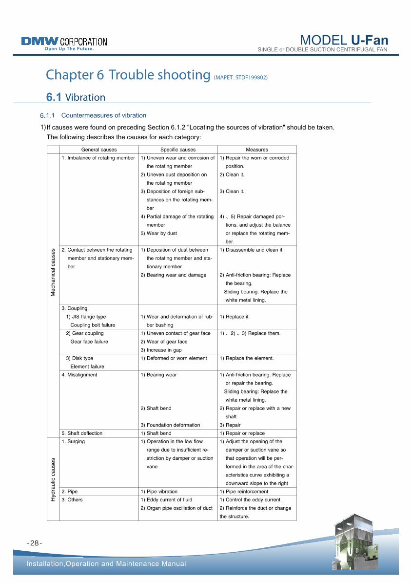
If causes were found on preceding Section 6.1.2 "Locating the sources of vibration" should be taken.
The following describes the causes for each category:
1)
1.1 Countermeasures of vibration 6.
General causes Specific causes Measures
s e s u a c l a c i n a h c e M
1. Imbalance of rotating member 1) Uneven wear and corrosion of the rotating member
2) Uneven dust deposition on the rotating member
3) Deposition of foreign sub- stances on the rotating mem- ber
4) Partial damage of the rotating member
5) Wear by dust
1) Repair the worn or corroded position.
2) Clean it.
3) Clean it.
4) 、5) Repair damaged por- tions, and adjust the balance or replace the rotating mem- ber.
2. Contact between the rotating member and stationary mem- ber
1) Deposition of dust between the rotating member and sta- tionary member
2) Bearing wear and damage
1) Disassemble and clean it.
2) Anti-friction bearing: Replace the bearing.
Sliding bearing: Replace the white metal lining.
3. Coupling 1) JIS flange type
Coupling bolt failure 1) Wear and deformation of rub-
ber bushing 1) Replace it.
2) Gear coupling Gear face failure
1) Uneven contact of gear face 2) Wear of gear face 3) Increase in gap
1) 、2) 、3) Replace them.
3) Disk type Element failure
1) Deformed or worn element 1) Replace the element.
4. Misalignment 1) Bearing wear
2) Shaft bend
3) Foundation deformation
1) Anti-friction bearing: Replace or repair the bearing.
Sliding bearing: Replace the white metal lining.
2) Repair or replace with a new shaft.
3) Repair 5. Shaft deflection 1) Shaft bend 1) Repair or replace
s e s u a c c i l u a r d y H
1. Surging 1) Operation in the low flow range due to insufficient re- striction by damper or suction vane
1) Adjust the opening of the damper or suction vane so that operation will be per- formed in the area of the char- acteristics curve exhibiting a downward slope to the right
2. Pipe 1) Pipe vibration 1) Pipe reinforcement 3. Others 1) Eddy current of fluid
2) Organ pipe oscillation of duct 1) Control the eddy current. 2) Reinforce the duct or change the structure.
MODEL U-Fan SINGLE or DOUBLE SUCTION CENTRIFUGAL FAN
- -
Installation,Operation and Maintenance Manual
Chapter 6 Trouble shooting (MAPET_STDF199802)
29
When the drive unit independently shows vibration, use shim liners to adjust the drive unit installation face
clearance, and tighten the bolts and nuts, then restart the operation.
①
When vibration is reduced according to the above step �, the rotating member may be unbalanced or drive unit
shaft is bent.
②
Measure the vibration at the drive unit shaft end (or coupling periphery). If any bend is detected, contact the
drive unit manufacturer.
③
If no bend is found out, the rotating member is unbalanced. The balance must be adjusted. ④
When no cause is found on the drive unit side: b)
Check for alignment.
Make adjustment if alignment fails to meet the tolerance.
①
Check for the squareness between the shaft and bearing. If the squareness fails to meet the tolerance, correct it. ②
If the cause is not clear, check according to the following steps: 2)
Drive unit independent operation
Remove the coupling locking bolts.
a)
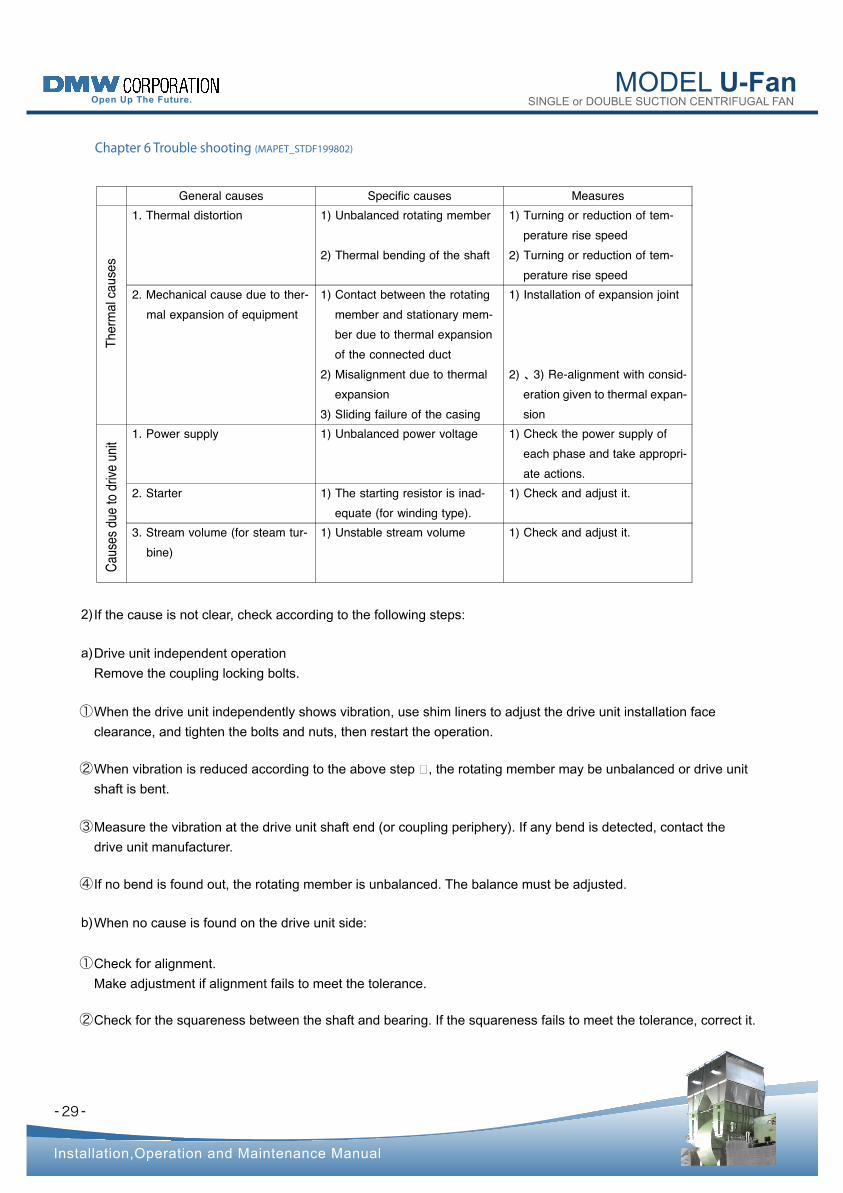
General causes Specific causes Measures
s e s u a c l a m
r e h T
1. Thermal distortion 1) Unbalanced rotating member
2) Thermal bending of the shaft
1) Turning or reduction of tem- perature rise speed
2) Turning or reduction of tem- perature rise speed
2. Mechanical cause due to ther- mal expansion of equipment
1) Contact between the rotating member and stationary mem- ber due to thermal expansion of the connected duct
2) Misalignment due to thermal expansion
3) Sliding failure of the casing
1) Installation of expansion joint
2) 、3) Re-alignment with consid- eration given to thermal expan- sion
t i n u e v i r d o t e u d s e s u a C
1. Power supply 1) Unbalanced power voltage 1) Check the power supply of each phase and take appropri- ate actions.
2. Starter 1) The starting resistor is inad- equate (for winding type).
1) Check and adjust it.
3. Stream volume (for steam tur- bine)
1) Unstable stream volume 1) Check and adjust it.
MODEL U-Fan SINGLE or DOUBLE SUCTION CENTRIFUGAL FAN
- -
Installation,Operation and Maintenance Manual
Chapter 6 Trouble shooting (MAPET_STDF199802)
30
When the sliding bearing is used, check the metal and its washers. If any problem is found out, repair the bearing. ④
Shaft bend
Disconnect the coupling and measure the shaft bend.
⑤
When the bend is 3/100mm (6/100mm on dial gauge reading ) or less, adjust the balance. ⑥
If a bend of 3/100mm or more is detected, a new shaft must be manufactured. ⑦
When the casing must be disassembled for adjustment: c)
In principle, internal inspection and cleaning are possible without disassembling the casing. ①
Check the impeller for wear, corrosion, and deposition of dust and foreign substances.
Cleaning must be made thoroughly.
②
If cleaning is insufficient, imbalance may remain without being corrected.
If the bearing vibration has exceeded the tolerance after operation, adjust the balance.
③
When the anti-friction bearing is used, check for bearing noise, or use a test instrument to perform diagnosis.
If any problem is found out, replace the bearing.
③
- -
MODEL U-Fan SINGLE or DOUBLE SUCTION CENTRIFUGAL FAN
Installation,Operation and Maintenance Manual
Chapter 6 Trouble shooting (MAPET_STDF199802)
6.2 Bearing temperature rise
31
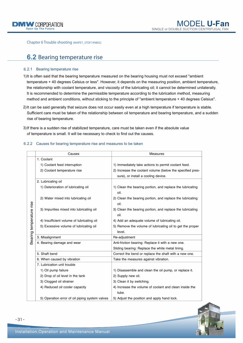
1)
It can be said generally that seizure does not occur easily even at a high temperature if temperature is stable.
Sufficient care must be taken of the relationship between oil temperature and bearing temperature, and a sudden
rise of bearing temperature.
2)
If there is a sudden rise of stabilized temperature, care must be taken even if the absolute value
of temperature is small. It will be necessary to check to find out the causes.
3)
It is often said that the bearing temperature measured on the bearing housing must not exceed "ambient
temperature + 40 degrees Celsius or less". However, it depends on the measuring position, ambient temperature,
the relationship with coolant temperature, and viscosity of the lubricating oil; it cannot be determined unilaterally.
It is recommended to determine the permissible temperature according to the lubrication method, measuring
method and ambient conditions, without sticking to the principle of "ambient temperature + 40 degrees Celsius".
2.2 Causes for bearing temperature rise and measures to be taken 6.
2.1 Bearing temperature rise 6.
Causes Measures
e s i r e r u t a r e p m
e t g n i r a e B
1. Coolant 1) Coolant feed interruption 2) Coolant temperature rise
1) Immediately take actions to permit coolant feed. 2) Increase the coolant volume (below the specified pres-
sure), or install a cooling device. 2. Lubricating oil
1) Deterioration of lubricating oil
2) Water mixed into lubricating oil
3) Impurities mixed into lubricating oil
4) Insufficient volume of lubricating oil 5) Excessive volume of lubricating oil
1) Clean the bearing portion, and replace the lubricating oil.
2) Clean the bearing portion, and replace the lubricating oil.
3) Clean the bearing portion, and replace the lubricating oil.
4) Add an adequate volume of lubricating oil. 5) Remove the volume of lubricating oil to get the proper
level. 3. Misalignment Re-adjustment 4. Bearing damage and wear Anti-friction bearing: Replace it with a new one.
Sliding bearing: Repla ce the white metal lining. 5. Shaft bend Correct the bend or replace the shaft with a new one. 6. When caused by vibration Take the measures against vibration. 7. Lubrication unit trouble
1) Oil pump failure 2) Drop of oil level in the tank 3) Clogged oil strainer 4) Reduced oil cooler capacity
5) Operation error of oil piping system valves
1) Disassemble and clean the oil pump, or replace it. 2) Supply new oil. 3) Clean it by switching. 4) Increase the volume of coolant and clean inside the
tube. 5) Adjust the position and apply hand lock.
- -
MODEL U-Fan SINGLE or DOUBLE SUCTION CENTRIFUGAL FAN
Installation,Operation and Maintenance Manual
Chapter 6 Trouble shooting (MAPET_STDF199802)
6.3 Performance degradation
32
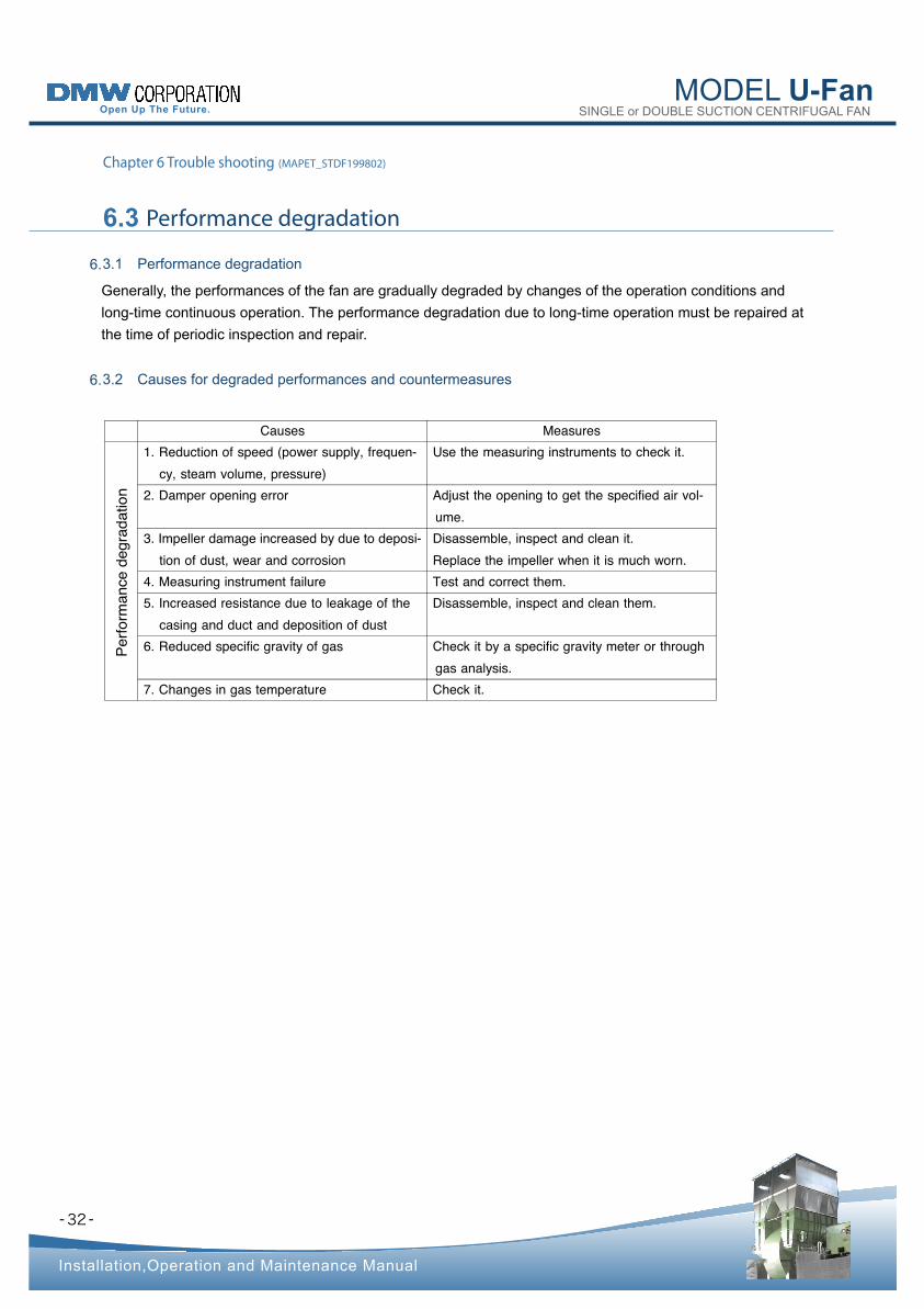
Generally, the performances of the fan are gradually degraded by changes of the operation conditions and
long-time continuous operation. The performance degradation due to long-time operation must be repaired at
the time of periodic inspection and repair.
3.1 Performance degradation 6.
3.2 Causes for degraded performances and countermeasures 6.
Causes Measures
n o i t a d a r g e d e c n a m
r o f r e P
1. Reduction of speed (power supply, frequen- cy, steam volume, pressure)
Use the measuring instruments to check it.
2. Damper opening error Adjust the opening to get the specified air vol- ume.
3. Impeller damage increased by due to deposi- tion of dust, wear and corrosion
Disassemble, inspect and clean it. Replace the impeller when it is much worn.
4. Measuring instrument failure Test and correct them. 5. Increased resistance due to leakage of the
casing and duct and deposition of dust Disassemble, inspect and clean them.
6. Reduced specific gravity of gas Check it by a specific gravity meter or through gas analysis.
7. Changes in gas temperature Check it.
- -
MODEL U-Fan SINGLE or DOUBLE SUCTION CENTRIFUGAL FAN
Installation,Operation and Maintenance Manual
Chapter 6 Trouble shooting (MAPET_STDF199802)
6.4 Fan troubles and its causes
33
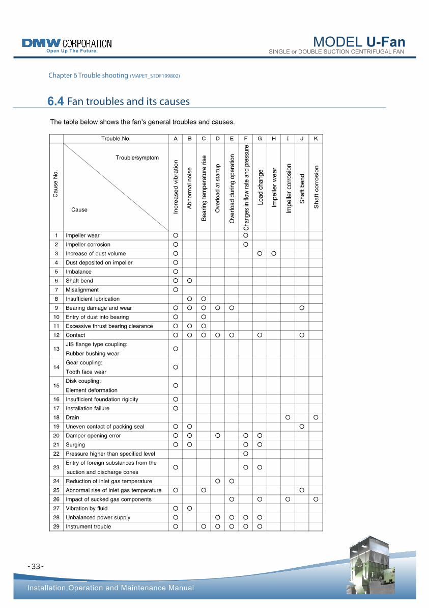
The table below shows the fan's general troubles and causes.
Trouble No. A B C D E F G H I J K
. o N
e s u a
C
Trouble/symptom
Cause
n o i t a r b i v d e s a e r c n I
e s i o n l a m
r o n b
A
e s i r e r u t a r e p m
e t g n i r a e B
p u t r a t s t a d a o l r e v O
n o i t a r e p o g n i r u d d a o l r e v O
e r u s s e r p d n a e t a r w o l f n i s e g n a h C
e g n a h c d a o L
r a e w
r e l l e p
m
I
n o i s o r r o c r e l l e p m
I
d n e b t f a h S
n o i s o r r o c t f a h S
1 Impeller wear ○ ○
2 Impeller corrosion ○ ○
3 Increase of dust volume ○ ○ ○
4 Dust deposited on impeller ○
5 Imbalance ○
6 Shaft bend ○ ○
7 Misalignment ○
8 Insufficient lubrication ○ ○
9 Bearing damage and wear ○ ○ ○ ○ ○ ○
10 Entry of dust into bearing ○ ○
11 Excessive thrust bearing clearance ○ ○ ○
12 Contact ○ ○ ○ ○ ○ ○ ○
13 JIS flange type coupling: Rubber bushing wear
○
14 Gear coupling: Tooth face wear
○
15 Disk coupling: Element deformation
○
16 Insufficient foundation rigidity ○
17 Installation failure ○
18 Drain ○ ○
19 Uneven contact of packing seal ○ ○ ○
20 Damper opening error ○ ○ ○ ○ ○
21 Surging ○ ○ ○ ○
22 Pressure higher than specified level ○
23 Entry of foreign substances from the suction and discharge cones
○ ○ ○
24 Reduction of inlet gas temperature ○ ○
25 Abnormal rise of inlet gas temperature ○ ○ ○
26 Impact of sucked gas components ○ ○ ○ ○
27 Vibration by fluid ○ ○
28 Unbalanced power supply ○ ○ ○ ○ ○
29 Instrument trouble ○ ○ ○ ○ ○ ○
- -
MODEL U-Fan SINGLE or DOUBLE SUCTION CENTRIFUGAL FAN
Installation,Operation and Maintenance Manual
7.1 Guarantee period
7.2 Scope of guarantee
7.3 Our guarantee is not applicable to
7.4 Our guarantee is applicable to
Chapter 7 Guarantee and Service (MAPEG_STDFB199802)
34
Contact the supplier you purchased the product from or our company if repair or inspection services are
necessary for your fan or blower. In the presence of any abnormalities in your fan or blower, stop its operation
immediately and carry out troubleshooting procedure. (Refer to Chapter 6 "Trouble shooting.")
In the case of malfunctions, please report to the supplier the items listed on the fan or blower's nameplate
(particularly, our serial number and type) and the state of malfunctions (abnormalities).
Any other information would also be helpful, if available.
One year from the date of delivery.
During the guarantee period, we supply repair parts and dispatch repair service men free of
charge for any damage that has occurred during your correct use due to our design or production
errors. However, our guarantee does not cover any other expenses.
Under the conditions of the guarantee, we are only responsible for the mending, repair or replacement of
defective parts or the supply of replacement parts.
The guarantee does not require us to compensate for any secondary losses.
Malfunctions resulting from incorrect operation, use or storage by the customer.
Malfunctions or damage after the expiration of the guaranty period.
Malfunctions due to repair or remodelling not performed by our company or our affiliated service comapnies.
Problems resulting from any applications not stipulated in the contract with us.
Malfunctions due to fires, acts of God, natural calamities or other force of majeure.
Problems resulting from the use of any parts that do not meet our specifications.
Consumables, packings(*1), sealats(*2), sliding parts(*3), etc.
•
•
•
•
•
•
•
(*1) O-rings, gaskets, etc.
(*2) Oil seals, mechanical seals etc.
(*3) Bearings
- -
MODEL U-Fan SINGLE or DOUBLE SUCTION CENTRIFUGAL FAN
Installation,Operation and Maintenance Manual
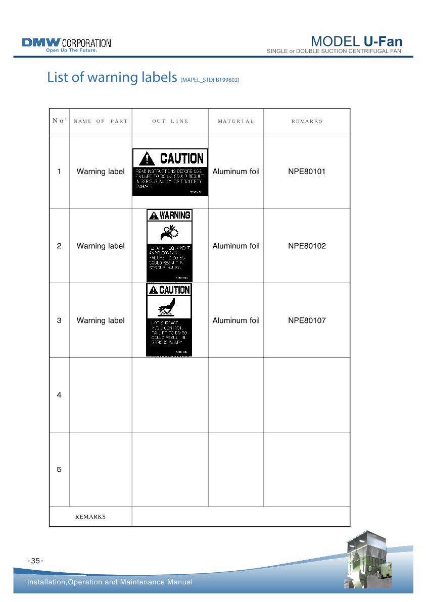
List of warning labels (MAPEL_STDFB199802)
35
No.
NAME OF PART OUT LINE MATERIAL REMARKS
1 Warning label Aluminum foil NPE80101
2 Warning label Aluminum foil NPE80102
3 Warning label Aluminum foil NPE80107
4
5
REMARKS
MODEL U-Fan SINGLE or DOUBLE SUCTION CENTRIFUGAL FAN
- -
Installation,Operation and Maintenance Manual
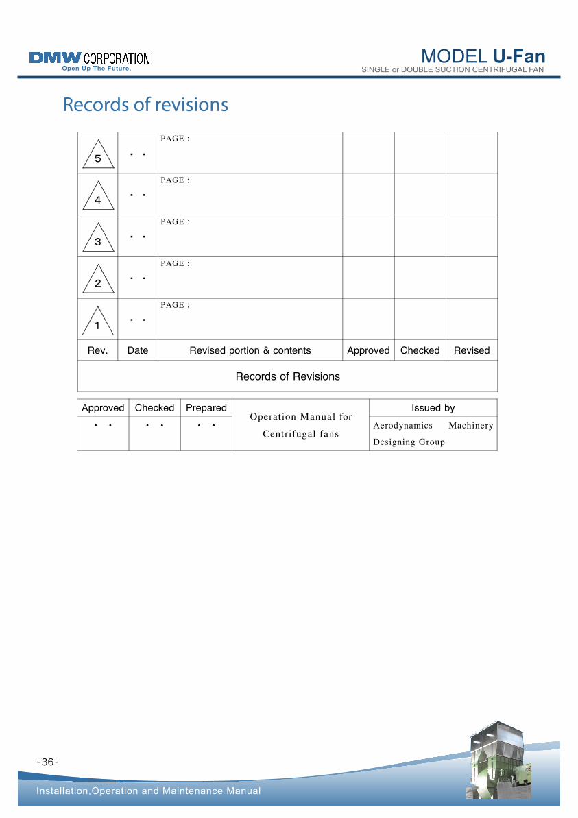
Records of revisions
Approved Checked Prepared Operation Manual for
Centrifugal fans
Issued by
・ ・ ・ ・ ・ ・ Aerodynamics Machinery
Designing Group
5 ・・
PAGE :
4 ・・
PAGE :
3 ・・
PAGE :
2 ・・
PAGE :
1・・
PAGE :
Rev. Date Revised portion & contents Approved Checked Revised
Records of Revisions
36
MODEL U-FanSINGLE or DOUBLE SUCTION CENTRIFUGAL FAN
- -
Installation,Operation and Maintenance Manual
Contacts
•
•
•
37
Head office
5-1, OMORI-KITA 1-CHOME, OTA-KU, TOKYO 143-8558, JAPAN
OVERSEAS TRADING SECT., INDUSTRIAL BUSINESS DEPT.
TELEPHONE : +81-3-3298-5123
TELEFAX : +81-3-3298-5146
Mishima plant
3-27, MIYOSHI-CHO, MISHIMA-SHI, SHIZUOKA 411-8560, JAPAN
INSPECTION & TEST SECT., QUALITY ASSURANCE DEPT.
TELEPHONE : +81-55-975-7900 TELEFAX : +81-55-975-5785
Aerodynamics Machinery Designing Group
TELEPHONE : +81-55-975-8053
TELEFAX : +81-55-975-8867
If you have any uncertain points or questions concerning the handing of the product, please call our branch
office, sales office or Business Division of the Head office nearest to you.
We look forward to your continued patronage.