Embed Size (px)
Citation preview
Installation Guide for Fountain Kit LA5000 and LA6000
© LiquidArt, LLC 401 S. Redwood St.
Phone 503-651-1344 • Fax 503-263-7699 www.liquidartfountains.com

2
Table of Contents UnPacking Your Fountain Kit .............................................................................. 4
Parts List.........................................................................................................................4 Parts List LA6000 Dual Fountain.................................................................................5
Installing Your Fountain Kit................................................................................. 6 Step 1 ...............................................................................................................................6 Step 2 ...............................................................................................................................7 Step 3 ...............................................................................................................................7 Step 4 ...............................................................................................................................7 Step 5 ...............................................................................................................................8 Step 6 ...............................................................................................................................9 Step 7 ...............................................................................................................................9 Step 8 a. Installing a Natural Rock.............................................................................10 Step 8 b. Installing a LiquidArt Synthetic Rock .......................................................10 Step 9 .............................................................................................................................11 Step 9 .............................................................................................................................11 Step 10 a. Natural Rock...............................................................................................11 Step 10 b. Synthetic Basalt Rock ................................................................................11 Step 10 c. Synthetic Granite Rock .................................. Error! Bookmark not defined. Step 11 ...........................................................................................................................12 Step 12 ...........................................................................................................................12 Step 13 ...........................................................................................................................13
Accessories ........................................................................................................... 14
Maintenance......................................................................................................... 15 Parts List.......................................................................................................................15 Winterization................................................................................................................15 Fountain Base and Grate.............................................................................................15
Fountain Base .......................................................................................................................... 15 Grating ..................................................................................................................................... 15
Pump .............................................................................................................................15 Features.................................................................................................................................... 15 Service and Maintenance ......................................................................................................... 15 Electrical Precautions............................................................................................................... 16
Limited Warranty ................................................................................................. 17
3
Unpacking Your Fountain Kit Check that all parts are present free from defects.
emove the two grate halves, including access panel, from the fountain base and set aside. Remove remaining components from the fountain base and check to see that all
parts are present and free from defects. Refer to parts list for a complete listing of components included with your fountain kit. If any of your fountain kit parts are missing or damaged please contact LiquidArt, LLC.
R
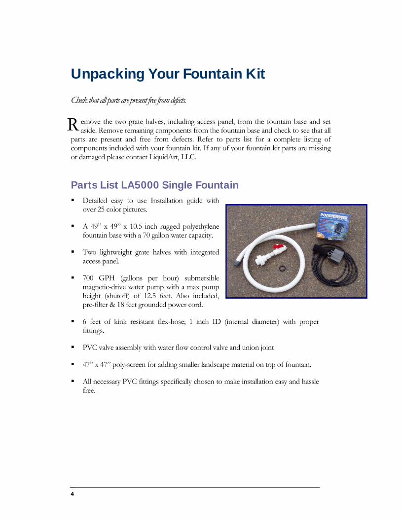
Parts List LA5000 Single Fountain Detailed easy to use Installation guide with
over 25 color pictures.
A 49” x 49” x 10.5 inch rugged polyethylene fountain base with a 70 gallon water capacity.
Two lightweight grate halves with integrated access panel.
700 GPH (gallons per hour) submersible magnetic-drive water pump with a max pump height (shutoff) of 12.5 feet. Also included, pre-filter & 18 feet grounded power cord.
6 feet of kink resistant flex-hose; 1 inch ID (internal diameter) with proper fittings.
PVC valve assembly with water flow control valve and union joint
47” x 47” poly-screen for adding smaller landscape material on top of fountain.
All necessary PVC fittings specifically chosen to make installation easy and hassle free.
4
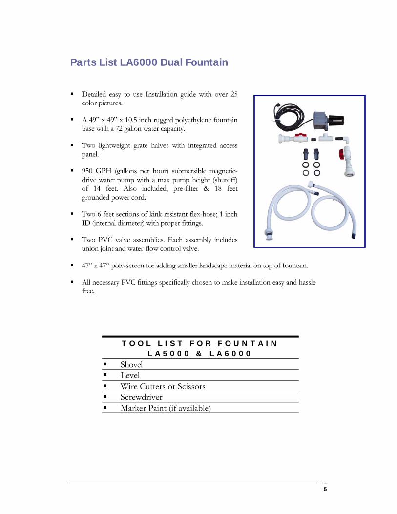
Parts List LA6000 Dual Fountain
Detailed easy to use Installation guide with over 25 color pictures.
A 49” x 49” x 10.5 inch rugged polyethylene fountain base with a 72 gallon water capacity.
Two lightweight grate halves with integrated access panel.
950 GPH (gallons per hour) submersible magnetic-drive water pump with a max pump height (shutoff) of 14 feet. Also included, pre-filter & 18 feet grounded power cord.
Two 6 feet sections of kink resistant flex-hose; 1 inch ID (internal diameter) with proper fittings.
Two PVC valve assemblies. Each assembly includes union joint and water-flow control valve.
47” x 47” poly-screen for adding smaller landscape material on top of fountain.
All necessary PVC fittings specifically chosen to make installation easy and hassle free.
T O O L L I S T F O R F O U N T A I N L A 5 0 0 0 & L A 6 0 0 0
Shovel Level Wire Cutters or Scissors Screwdriver Marker Paint (if available)
5
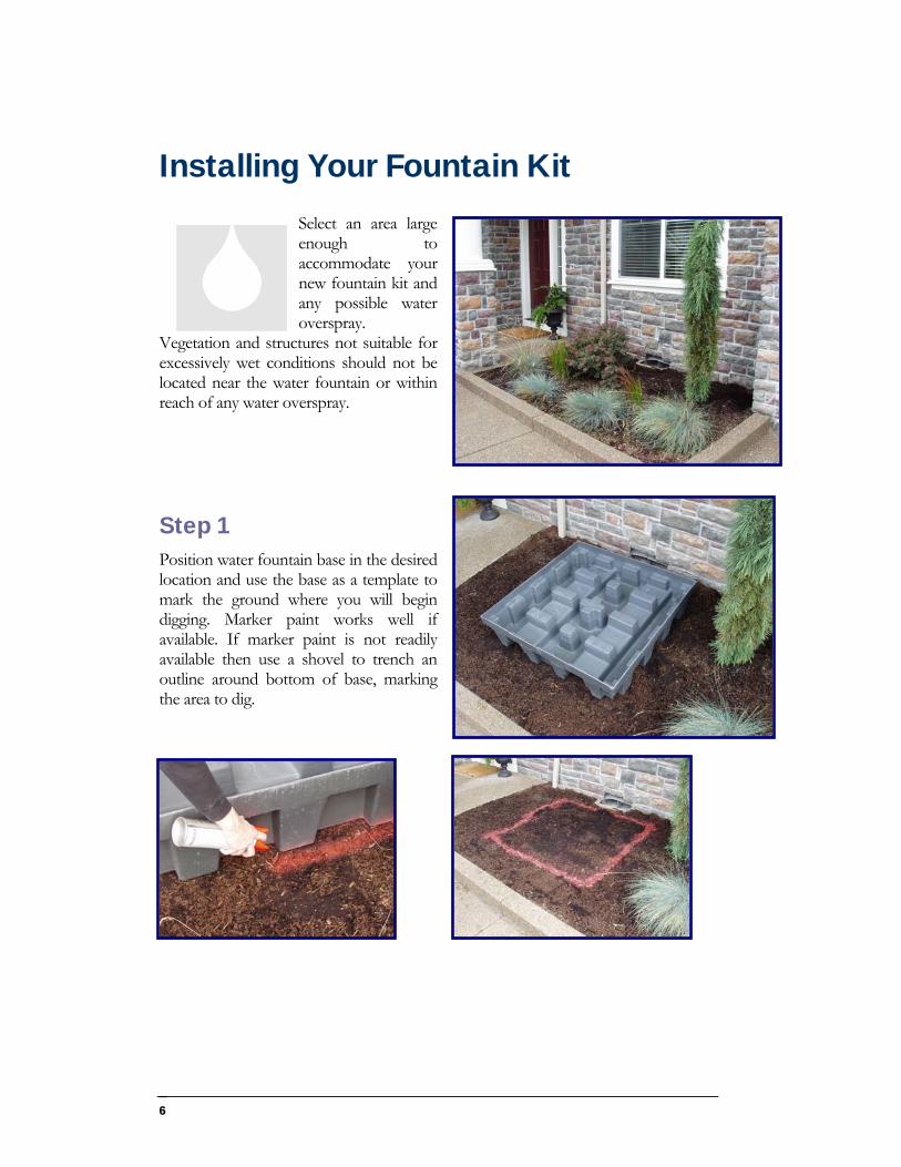
Installing Your Fountain Kit Select an area large enough to accommodate your new fountain kit and any possible water overspray.
Vegetation and structures not suitable for excessively wet conditions should not be located near the water fountain or within reach of any water overspray.
Step 1 Position water fountain base in the desired location and use the base as a template to mark the ground where you will begin digging. Marker paint works well if available. If marker paint is not readily available then use a shovel to trench an outline around bottom of base, marking the area to dig.
6
7
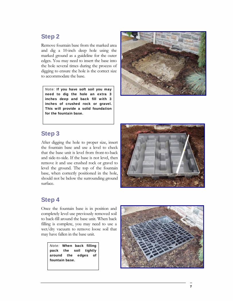
Step 2 Remove fountain base from the marked area and dig a 10-inch deep hole using the marked ground as a guideline for the outer edges. You may need to insert the base into the hole several times during the process of digging to ensure the hole is the correct size to accommodate the base.
Note: If you have soft soil you may need to dig the hole an extra 3 inches deep and back fill with 3 inches of crushed rock or gravel. This will provide a solid foundation for the fountain base.
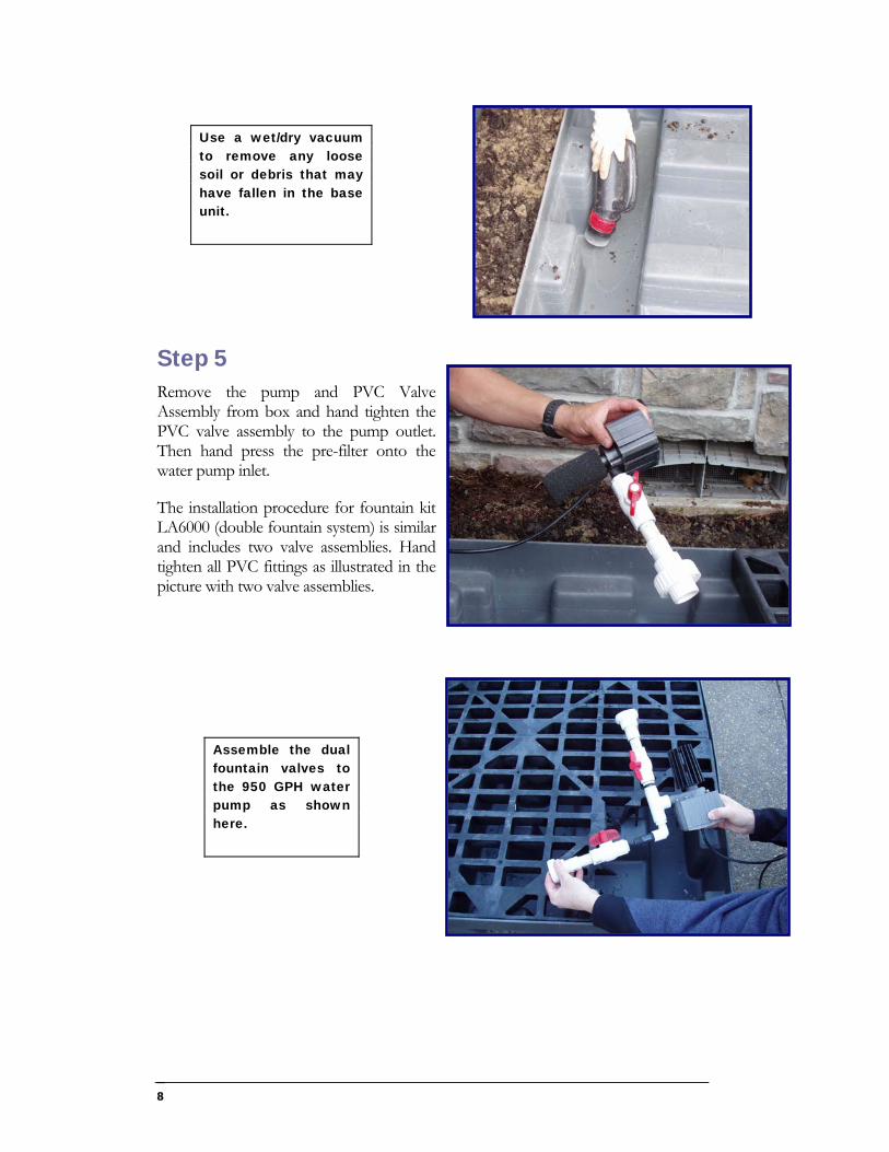
Step 3 After digging the hole to proper size, insert the fountain base and use a level to check that the base unit is level from front-to-back and side-to-side. If the base is not level, then remove it and use crushed rock or gravel to level the ground. The top of the fountain base, when correctly positioned in the hole, should not be below the surrounding ground surface.
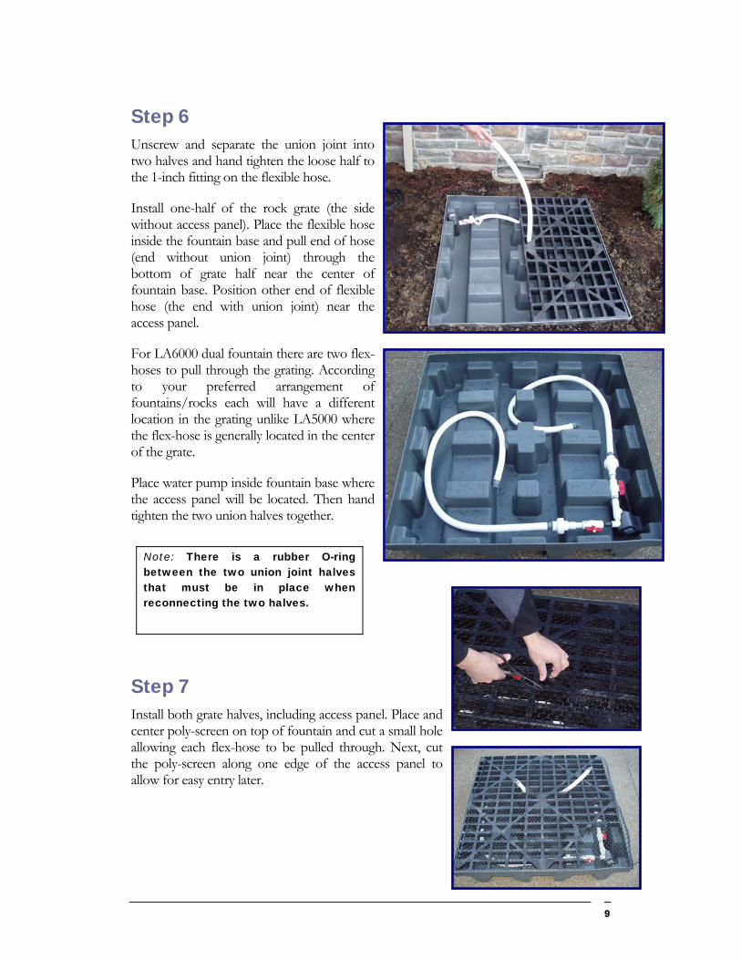
Step 4 Once the fountain base is in position and completely level use previously removed soil to back-fill around the base unit. When back filling is complete, you may need to use a wet/dry vacuum to remove loose soil that may have fallen in the base unit.
Note: When back filling pack the soil tightly around the edges of fountain base.
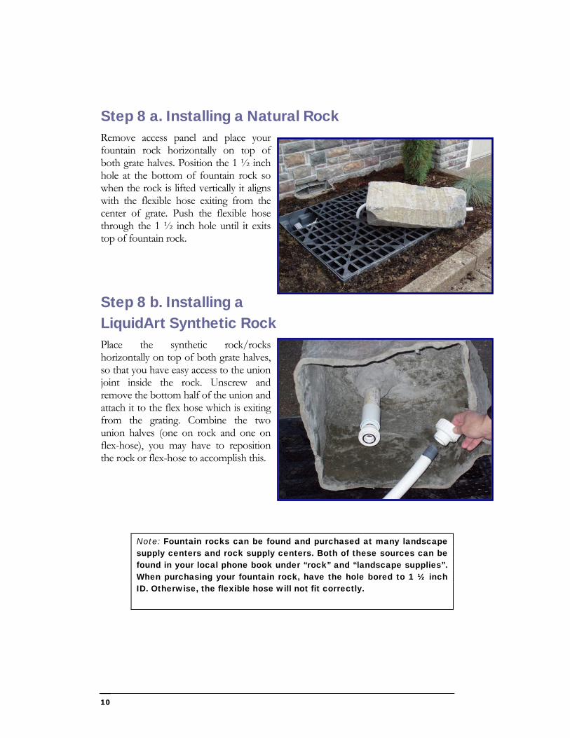
Use a wet/dry vacuum to remove any loose soil or debris that may have fallen in the base unit.
Step 5 Remove the pump and PVC Valve Assembly from box and hand tighten the PVC valve assembly to the pump outlet. Then hand press the pre-filter onto the water pump inlet.
The installation procedure for fountain kit LA6000 (double fountain system) is similar and includes two valve assemblies. Hand tighten all PVC fittings as illustrated in the picture with two valve assemblies.
Assemble the dual fountain valves to the 950 GPH water pump as shown here.
8
Step 6 Unscrew and separate the union joint into two halves and hand tighten the loose half to the 1-inch fitting on the flexible hose.
Install one-half of the rock grate (the side without access panel). Place the flexible hose inside the fountain base and pull end of hose (end without union joint) through the bottom of grate half near the center of fountain base. Position other end of flexible hose (the end with union joint) near the access panel.
For LA6000 dual fountain there are two flex-hoses to pull through the grating. According to your preferred arrangement of fountains/rocks each will have a different location in the grating unlike LA5000 where the flex-hose is generally located in the center of the grate.
Place water pump inside fountain base where the access panel will be located. Then hand tighten the two union halves together.
Note: There is a rubber O-ring between the two union joint halves that must be in place when reconnecting the two halves.
Step 7 Install both grate halves, including access panel. Place and center poly-screen on top of fountain and cut a small hole allowing each flex-hose to be pulled through. Next, cut the poly-screen along one edge of the access panel to allow for easy entry later.
9
Step 8 a. Installing a Natural Rock Remove access panel and place your fountain rock horizontally on top of both grate halves. Position the 1 ½ inch hole at the bottom of fountain rock so when the rock is lifted vertically it aligns with the flexible hose exiting from the center of grate. Push the flexible hose through the 1 ½ inch hole until it exits top of fountain rock.
Step 8 b. Installing a LiquidArt Synthetic Rock Place the synthetic rock/rocks horizontally on top of both grate halves, so that you have easy access to the union joint inside the rock. Unscrew and remove the bottom half of the union and attach it to the flex hose which is exiting from the grating. Combine the two union halves (one on rock and one on flex-hose), you may have to reposition the rock or flex-hose to accomplish this.
Note: Fountain rocks can be found and purchased at many landscape supply centers and rock supply centers. Both of these sources can be found in your local phone book under “rock” and “landscape supplies”. When purchasing your fountain rock, have the hole bored to 1 ½ inch ID. Otherwise, the flexible hose will not fit correctly.
10
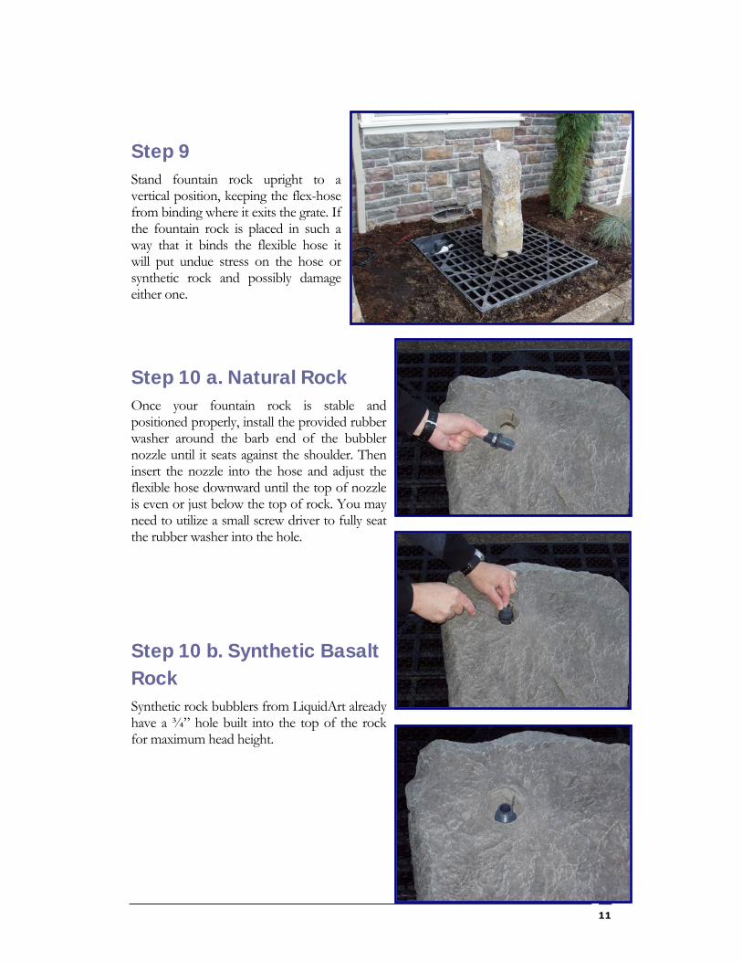
Step 9 Stand fountain rock upright to a vertical position, keeping the flex-hose from binding where it exits the grate. If the fountain rock is placed in such a way that it binds the flexible hose it will put undue stress on the hose or synthetic rock and possibly damage either one.
Step 10 a. Natural Rock Once your fountain rock is stable and positioned properly, install the provided rubber washer around the barb end of the bubbler nozzle until it seats against the shoulder. Then insert the nozzle into the hose and adjust the flexible hose downward until the top of nozzle is even or just below the top of rock. You may need to utilize a small screw driver to fully seat the rubber washer into the hole.
Step 10 b. Synthetic Basalt Rock Synthetic rock bubblers from LiquidArt already have a ¾” hole built into the top of the rock for maximum head height.
11
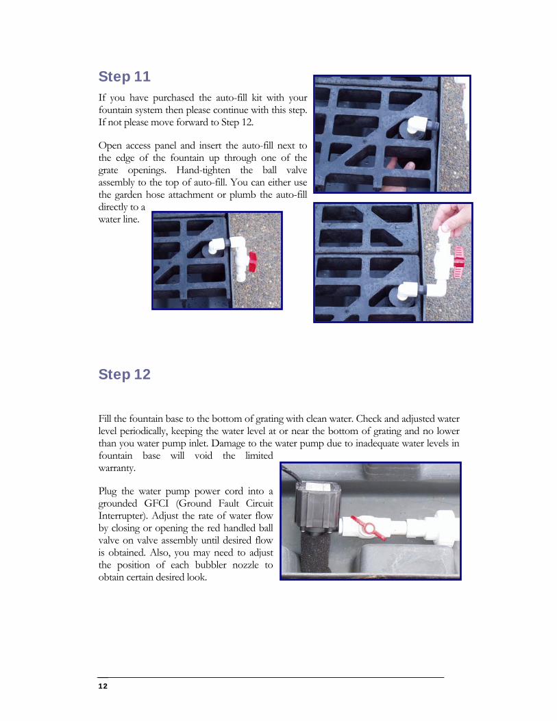
Step 11 If you have purchased the auto-fill kit with your fountain system then please continue with this step. If not please move forward to Step 12.
Open access panel and insert the auto-fill next to the edge of the fountain up through one of the grate openings. Hand-tighten the ball valve assembly to the top of auto-fill. You can either use the garden hose attachment or plumb the auto-fill directly to a water line.
Step 12
Fill the fountain base to the bottom of grating with clean water. Check and adjusted water level periodically, keeping the water level at or near the bottom of grating and no lower than you water pump inlet. Damage to the water pump due to inadequate water levels in fountain base will void the limited warranty.
Plug the water pump power cord into a grounded GFCI (Ground Fault Circuit Interrupter). Adjust the rate of water flow by closing or opening the red handled ball valve on valve assembly until desired flow is obtained. Also, you may need to adjust the position of each bubbler nozzle to obtain certain desired look.
12
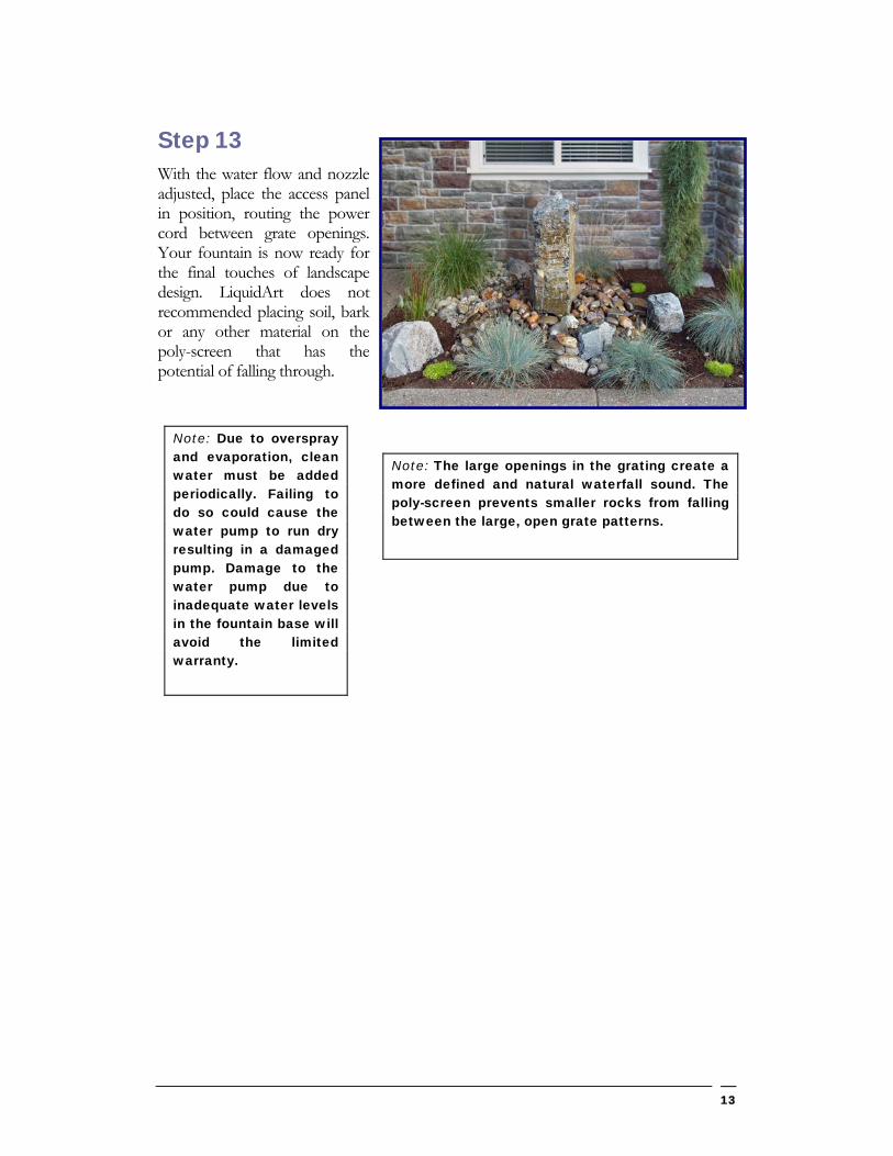
Step 13 With the water flow and nozzle adjusted, place the access panel in position, routing the power cord between grate openings. Your fountain is now ready for the final touches of landscape design. LiquidArt does not recommended placing soil, bark or any other material on the poly-screen that has the potential of falling through.
Note: The large openings in the grating create a more defined and natural waterfall sound. The poly-screen prevents smaller rocks from falling between the large, open grate patterns.
Note: Due to overspray and evaporation, clean water must be added periodically. Failing to do so could cause the water pump to run dry resulting in a damaged pump. Damage to the water pump due to inadequate water levels in the fountain base will avoid the limited warranty.
13
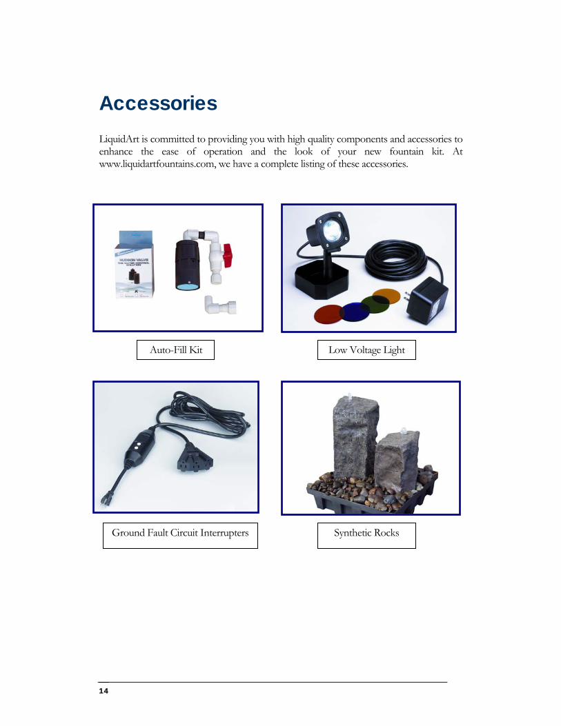
Accessories LiquidArt is committed to providing you with high quality components and accessories to enhance the ease of operation and the look of your new fountain kit. At www.liquidartfountains.com, we have a complete listing of these accessories.
t
14
Auto-Fill Ki
s
Low Voltage Light
Ground Fault Circuit Interrupter Synthetic Rocks
Maintenance
Parts Replacement parts are available by contacting LiquidArt Fountain Kits by calling 503-651-1344, email at [email protected] or by writing to:
LiquidArt, LLC
401 S. Redwood St.
Canby, OR 97013
Winterization In colder climates where temperatures can reach below 32 degrees Fahrenheit it is recommended that all water be removed from the fountain kit. Also, remove the water pump, by disconnecting the union joint, and store in temperature-controlled atmosphere above freezing.
Fountain Base and Grate Fountain Base Check and adjust water level periodically, keeping the water level at or near the bottom of grating and no lower than you water pump inlet. Also, remove any dirt, rock or debris from inside the fountain base that may cause damage to the water pump or flexible hose.
Grating Periodically inspect grating and mesh screen for damage, replace if necessary.
Pump Features The pump is a magnetically driven centrifugal water pump. It has no seals to wear and contains no oil. All electrical components are encapsulated in epoxy. The energy used is approximately ½ of regular driven pumps. The pre-filter is provided for use in situations where deposits in the water could clog or damage the pump. LiquidArt highly recommends using the pre-filter for all situations.
Service and Maintenance Periodically inspect and clean pre-filter. To clean remove pre-filter from water pump and rinse using clean water. Replace the pre-filter if it is damaged or torn.
15
The housing should occasionally be removed to clean and inspect the impeller assembly. The impeller is the only serviceable item and can be pulled out of the body. Do not take the impeller apart. If it is worn or broken, the entire impeller assembly should be replaced. This will restore pump to original capacity. Pumps taken out of service for an extended period with fluid inside run the risk of forming a crust, which may prevent subsequent starting. Saltwater should be flushed out with fresh water. Always check electrical cord for sharp bends, which can cause premature cracking. Do not use power cord to lift or move pump.
Electrical Precautions Always use a properly grounded outlet. Do not immerse plug in water. DO NOT REACH INTO WATER TO REMOVE PLUG. TURN OFF CIRCUIT FIRST. A “drip loop” should be provided. The “drip loop” is a loop in the electrical cord below the level of the receptacle or plug that prevents water from traveling along the cord. The National Electric Code requires that ground fault circuit interrupter (GFCI) be installed in the branch circuit supplying fountain or pond equipment. LiquidArt has several styles of GFCI units available. NEVER REMOVE GROUND PIN FROM ELECTRICAL PLUG. WARNING: FOR YOUR PROTECTION ALWAYS UNPLUG THE PUMP UNIT FROM ITS POWER SOURCE BEFORE INSTALLING OR SERVICING. SHOULD THE UNIT APPEAR TO BE NOT WORKING DO NOT REACH, REMOVE, OR DISASSEMBLE BEFORE YOU DISCONNECT POWER.
16
Limited Warranty LIQUID ART FOUNTAIN KIT MODEL LA5000 & LA6000
This limited warranty is given to the original consumer purchaser of this LiquidArt Fountain Kit (the "Kit") by LiquidArt, LLC, 401 S. Redwood Street, Canby, Oregon 97013.
LiquidArt, LLC ("LiquidArt"), warrants that the Kit, including all parts and components thereof, to be free of defects in material and workmanship. If you have a question regarding your Kit, please feel free to call or write us.
The Kit (except for the pump) comes with a one-year limited warranty commencing on the original date of purchase. The pump comes with a three-year/one-year limited warranty for the pump unit. LiquidArt will repair or replace the pump unit if it is found to be defective as follows: the pump body housing and power cord are covered for a period of three years from the original date of purchase; and the pump impeller and internal moving parts are covered for a period of one year from the original date of purchase. This warranty excludes any replaceable filters or filtering material supplied with the pump unit. Altering the pump unit or cord in any manner voids the pump warranty. LiquidArt's warranty with respect to the Kit, including the pump unit, is limited to replacement or repair of the product or parts found to be defective within the warranty period and under the conditions of the warranty.
This warranty does not cover the Kit or the pump if any component of the Kit (i) is improperly installed, (ii) has not been cleaned or maintained as recommended in the installation instructions, (iii) has been altered or misused in any manner inconsistent with its intended use, (iv) has been subjected to severe conditions, including but not limited to running the pump without an adequate water level, (v) is damaged as a result of failing to clean the pump filter and basin as recommended in the installation instructions, or (vi) is damaged as a result of failing to remove the pump and drain the collection tub if the outside air temperature falls below freezing. This warranty is given only to the purchaser of the product and is not transferable or assignable.
All warranty claims must be directed to LiquidArt at 401 S. Redwood St., Canby, OR 97013 to obtain a return authorization number before returning any product to LiquidArt. LiquidArt is not responsible for the cost of removal of the Kit, damages due to removal, expenses incurred in shipping the Kit or parts to or from LiquidArt, or the installation of the repaired or replacement parts. You must bear these expenses.
To the extent permissible by law, LiquidArt hereby disclaims all warranties, except the limited warranty stated above, including all implied warranties of merchantability, fitness for a particular purpose, title and non-infringement, except to the extent any implied warranty imposed by state law. Any such implied warranty imposed by state consumer law is limited to one year from the original date of purchase.
IN NO EVENT SHALL LIQUIDART BE LIABLE FOR INCIDENTAL OR CONSEQUENTIAL DAMAGES OF ANY NATURE OR KIND OR FOR DAMAGES TO PERSONS OR PROPERTY, INCLUDING ANY DAMAGE RESULTING FROM THE USE OF THE KIT OR ITS COMPONENTS.
Some states do not allow limitations on how long an implied warranty lasts, or the exclusion or limitation of incidental or consequential damages, so the above limitations may not apply to you.
This limited warranty is valid only in the United States of America, and it does not apply to Kits sold or installed in any other country.
17