Embed Size (px)
Citation preview
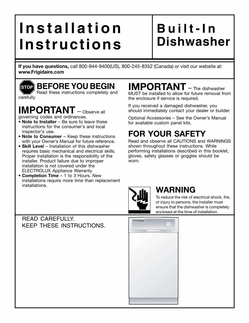
I n s t a l l a t i o nInstruct ions
B u i l t - I nDishwasher
If you have questions, call 800-944-9400(US), 800-245-8352 (Canada) or visit our website at:www.Frigidaire.com
IMPORTANT – The dishwasherMUST be installed to allow for future removal fromthe enclosure if service is required.
If you received a damaged dishwasher, youshould immediately contact your dealer or builder.
Optional Accessories – See the Owner’s Manualfor available custom panel kits.
FOR YOUR SAFETYRead and observe all CAUTIONS and WARNINGSshown throughout these instructions. Whileperforming installations described in this booklet,gloves, safety glasses or goggles should beworn.
BEFORE YOU BEGINRead these instructions completely and
carefully.
IMPORTANT – Observe allgoverning codes and ordinances.• Note to Installer – Be sure to leave these
instructions for the consumer's and localinspector's use.
• Note to Consumer – Keep these instructionswith your Owner’s Manual for future reference.
• Skill Level – Installation of this dishwasherrequires basic mechanical and electrical skills.Proper installation is the responsibility of theinstaller. Product failure due to improperinstallation is not covered under theELECTROLUX Appliance Warranty.
• Completion Time – 1 to 3 Hours. Newinstallations require more time than replacementinstallations.
WARNINGTo reduce the risk of electrical shock, fire,or injury to persons, the installer mustensure that the dishwasher is completelyenclosed at the time of installation.
READ CAREFULLY.KEEP THESE INSTRUCTIONS.
2
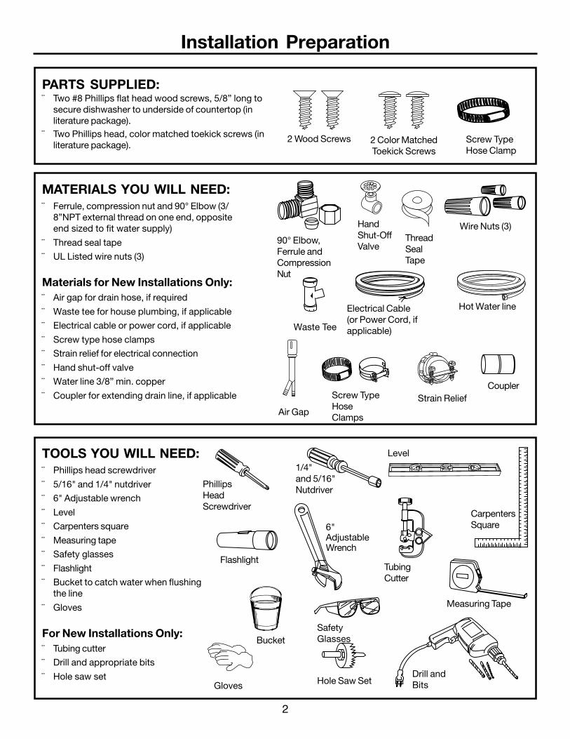
TOOLS YOU WILL NEED:¨ Phillips head screwdriver
¨ 5/16" and 1/4" nutdriver
¨ 6" Adjustable wrench
¨ Level
¨ Carpenters square
¨ Measuring tape
¨ Safety glasses
¨ Flashlight
¨ Bucket to catch water when flushingthe line
¨ Gloves
For New Installations Only:¨ Tubing cutter
¨ Drill and appropriate bits
¨ Hole saw set
Installation Preparation
PARTS SUPPLIED:¨ Two #8 Phillips flat head wood screws, 5/8” long to
secure dishwasher to underside of countertop (inliterature package).
¨ Two Phillips head, color matched toekick screws (inliterature package).
MATERIALS YOU WILL NEED:¨ Ferrule, compression nut and 90° Elbow (3/
8”NPT external thread on one end, oppositeend sized to fit water supply)
¨ Thread seal tape
¨ UL Listed wire nuts (3)
Materials for New Installations Only:¨ Air gap for drain hose, if required
¨ Waste tee for house plumbing, if applicable
¨ Electrical cable or power cord, if applicable
¨ Screw type hose clamps
¨ Strain relief for electrical connection
¨ Hand shut-off valve
¨ Water line 3/8” min. copper
¨ Coupler for extending drain line, if applicable
90° Elbow,Ferrule andCompressionNut
Wire Nuts (3)
Waste Tee
Electrical Cable(or Power Cord, ifapplicable)
Hot Water line
Screw TypeHoseClamps
Coupler
HandShut-OffValve
2 Wood Screws
Hole Saw Set
Measuring Tape
TubingCutter
1/4"and 5/16"Nutdriver
SafetyGlasses
6"AdjustableWrench
Bucket
Flashlight
Gloves
CarpentersSquare
Level
ThreadSealTape
Air Gap
Strain Relief
2 Color MatchedToekick Screws
Drill andBits
PhillipsHeadScrewdriver
Screw TypeHose Clamp
3
Installation Preparation
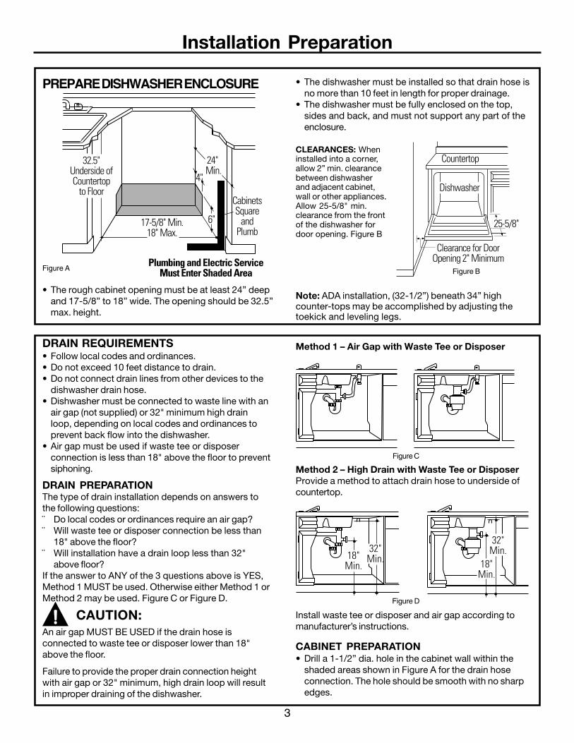
Figure C
Figure D
Install waste tee or disposer and air gap according tomanufacturer’s instructions.
CABINET PREPARATION• Drill a 1-1/2” dia. hole in the cabinet wall within the
shaded areas shown in Figure A for the drain hoseconnection. The hole should be smooth with no sharpedges.
Method 1 – Air Gap with Waste Tee or Disposer
Method 2 – High Drain with Waste Tee or DisposerProvide a method to attach drain hose to underside ofcountertop.
CabinetsSquare
andPlumb
Plumbing and Electric ServiceMust Enter Shaded Area
32.5"Underside ofCountertop
to Floor
24" Min.
17-5/8" Min.18" Max.
4"
6"
Clearance for DoorOpening 2" Minimum
Countertop
Dishwasher
25-5/8"
18"Min.
32"Min.
32"Min.
18"Min.
PREPARE DISHWASHER ENCLOSURE
Figure A
• The rough cabinet opening must be at least 24” deepand 17-5/8” to 18” wide. The opening should be 32.5”max. height.
CLEARANCES: Wheninstalled into a corner,allow 2” min. clearancebetween dishwasherand adjacent cabinet,wall or other appliances.Allow 25-5/8" min.clearance from the frontof the dishwasher fordoor opening. Figure B
Note: ADA installation, (32-1/2”) beneath 34” highcounter-tops may be accomplished by adjusting thetoekick and leveling legs.
Figure B
DRAIN REQUIREMENTS• Follow local codes and ordinances.• Do not exceed 10 feet distance to drain.• Do not connect drain lines from other devices to the
dishwasher drain hose.• Dishwasher must be connected to waste line with an
air gap (not supplied) or 32" minimum high drainloop, depending on local codes and ordinances toprevent back flow into the dishwasher.
• Air gap must be used if waste tee or disposerconnection is less than 18" above the floor to preventsiphoning.
DRAIN PREPARATIONThe type of drain installation depends on answers tothe following questions:¨ Do local codes or ordinances require an air gap?¨ Will waste tee or disposer connection be less than
18" above the floor?¨ Will installation have a drain loop less than 32"
above floor?If the answer to ANY of the 3 questions above is YES,Method 1 MUST be used. Otherwise either Method 1 orMethod 2 may be used. Figure C or Figure D.
An air gap MUST BE USED if the drain hose isconnected to waste tee or disposer lower than 18"above the floor.
Failure to provide the proper drain connection heightwith air gap or 32" minimum, high drain loop will resultin improper draining of the dishwasher.
• The dishwasher must be installed so that drain hose isno more than 10 feet in length for proper drainage.
• The dishwasher must be fully enclosed on the top,sides and back, and must not support any part of theenclosure.
CAUTION:

4
Installation Preparation
Cabinet Preparation & Wire Routing• The wiring may enter the opening from either side, rear
or the floor within the shaded area.• Cut a 1-1/2” max. dia. hole to admit the electrical
cable. The hole must be free of sharp edges. If thecabinet wall is metal, the hole edge must be coveredwith a bushing.
• Cable direct connections may pass through the samehole as the drain hose and hot water line, if convenient.If cabinet wall is metal, the hole edge must be coveredwith a bushing.NOTE: Power cords with plug must pass through aseparate hole.
Electrical Connection to DishwasherElectrical connection is on the right front of dishwasher.• For cable direct connections the cable must be routed
as shown in Figure E. Cable must extend a minimum of24” from the rear wall.
• For power cord connections, install a 3-pronggrounding type receptacle. The power-supplyreceptacle for the appliance shall be installed in acabinet or on a wall adjacent to the undercounterspace in which the appliance is to be installed.
WARNINGFOR PERSONAL SAFETY: Removehouse fuse or open circuit breakerbefore beginning installation. Do notuse an extension cord or adapter plugwith this appliance.
PREPARE ELECTRICAL WIRING
Electrical Requirements• This appliance must be supplied with 120V, 60 Hz.,
and connected to an individual properly groundedbranch circuit, protected by a 15 or 20 ampere circuitbreaker or time delay fuse.
• Wiring must be 2 wire with ground.• If the electrical supply does not meet the above
requirements, call a licensed electrician beforeproceeding.
Grounding Instructions – Cable DirectThis appliance must be connected to a grounded metal,permanent wiring system, or an equipment groundingconductor must be run with the circuit conductors and beconnected to the equipment grounding terminal or leadon the appliance.
Grounding Instructions – Power CordModelshis appliance must be grounded. In the event of amalfunction or breakdown, grounding will reduce the riskof electrical shock by providing a path of least resistancefor electric current. The plug must be plugged into anappropriate outlet that is installed and grounded inaccordance with local codes and ordinances.
WARNINGThe improper connection of theequipment grounding conductor canresult in a risk of electric shock.Check with a qualified electrician orservice representative if you are indoubt that the appliance is properlygrounded.
White
24"from Wall
3"from
Cabinet
GroundBlack
1-1/2" Dia.Hole (Max.)
Figure E
5
Installation Instructions
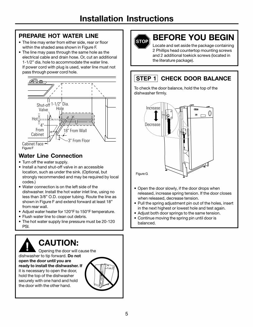
PREPARE HOT WATER LINE• The line may enter from either side, rear or floor
within the shaded area shown in Figure F.• The line may pass through the same hole as the
electrical cable and drain hose. Or, cut an additional1-1/2” dia. hole to accommodate the water line.If power cord with plug is used, water line must notpass through power cord hole.
Water Line Connection• Turn off the water supply.• Install a hand shut-off valve in an accessible
location, such as under the sink. (Optional, butstrongly recommended and may be required by localcodes.)
• Water connection is on the left side of thedishwasher. Install the hot water inlet line, using noless than 3/8” O.D. copper tubing. Route the line asshown in Figure F and extend forward at least 18”from rear wall.
• Adjust water heater for 120°F to 150°F temperature.• Flush water line to clean out debris.• The hot water supply line pressure must be 20-120
PSI.
CAUTION:Opening the door will cause the
dishwasher to tip forward. Do notopen the door until you areready to install the dishwasher. Ifit is necessary to open the door,hold the top of the dishwashersecurely with one hand and holdthe door with the other hand.
• Open the door slowly, if the door drops whenreleased, increase spring tension. If the door closeswhen released, decrease tension.
• Pull the spring adjustment pin out of the holes, insertin the next highest or lowest hole and test again.
• Adjust both door springs to the same tension.• Continue moving the spring pin until door is
balanced.
STEP 1 CHECK DOOR BALANCE
To check the door balance, hold the top of thedishwasher firmly.
BEFORE YOU BEGINLocate and set aside the package containing2 Phillips head countertop mounting screwsand 2 additional toekick screws (located inthe literature package).
Cabinet Face
Shut-offValve
3" From Floor
18" From Wall4"
FromCabinet
1-1/2" Dia.Hole
Hot
Increase
Decrease
Figure F
Figure G

6
Installation Instructions
STEP 3 REMOVE TOEKICK
• Remove the 4 toekick screws. Lift off the 2 piecetoekick.
• Measure installation height and dishwasher height.Extend leveling legs out from the dishwasher base,1/4" less than installation height.
STEP 2 ADJUST LEVELING LEGS
• Move the dishwasher close to the installation locationand lay it on its back.
Adjust toInstallation
Height
Remove4 ToekickScrews
90°Elbow
FillHose
ThreadSeal Tape
WaterValve
Bracket
STEP 4 INSTALL 90° ELBOW
• Wrap 90° elbow with thread seal tape.• Install a 90° elbow onto the water valve.
Figure H
• Do not over tighten 90° elbow, water valve bracketcould bend or water valve fitting could break.
• Position the end of the elbow to face the rear of thedishwasher.
Figure L
Figure J
7
Power Cord(If Used)
Insulation Blanket Water
Line
HouseWiring
Drain Hose
MaximumDrain HoseLength 10'
Installation Instructions
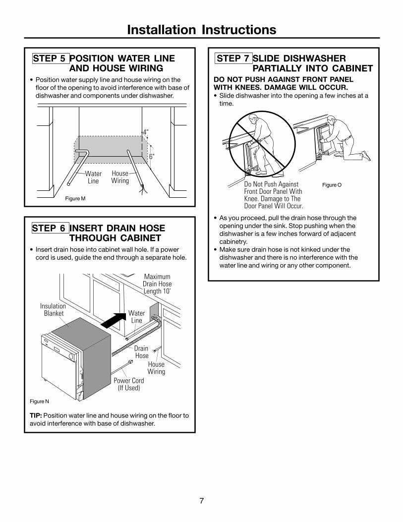
STEP 7 SLIDE DISHWASHERPARTIALLY INTO CABINET
DO NOT PUSH AGAINST FRONT PANELWITH KNEES. DAMAGE WILL OCCUR.• Slide dishwasher into the opening a few inches at a
time.
TIP: Position water line and house wiring on the floor toavoid interference with base of dishwasher.
STEP 6 INSERT DRAIN HOSETHROUGH CABINET
• Insert drain hose into cabinet wall hole. If a powercord is used, guide the end through a separate hole.
STEP 5 POSITION WATER LINEAND HOUSE WIRING
• Position water supply line and house wiring on thefloor of the opening to avoid interference with base ofdishwasher and components under dishwasher.
WaterLine
HouseWiring
4"
6"
Do Not Push AgainstFront Door Panel With Knee. Damage to The Door Panel Will Occur.
Figure M
Figure N
Figure O
• As you proceed, pull the drain hose through theopening under the sink. Stop pushing when thedishwasher is a few inches forward of adjacentcabinetry.
• Make sure drain hose is not kinked under thedishwasher and there is no interference with thewater line and wiring or any other component.
8
Do Not Push AgainstFront Door Panel With Knee. Damage to The Door Panel Will Occur.
Reposition Dishwasherby Grasping BothSides With Hands
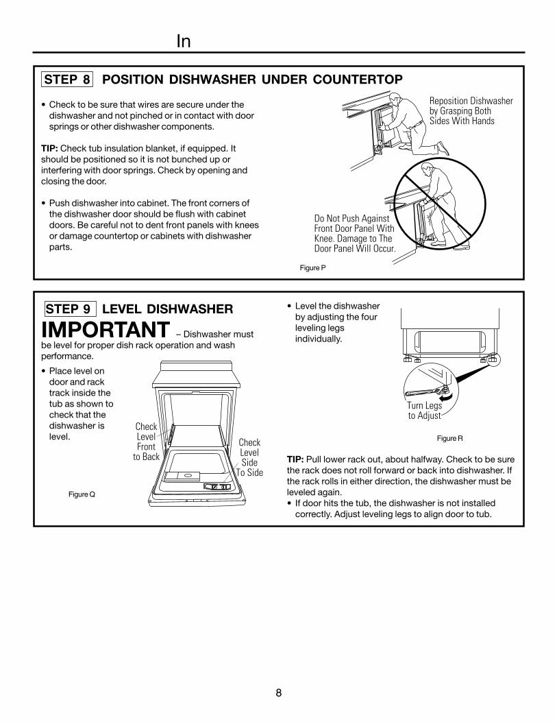
STEP 8 POSITION DISHWASHER UNDER COUNTERTOP
• Check to be sure that wires are secure under thedishwasher and not pinched or in contact with doorsprings or other dishwasher components.
TIP: Check tub insulation blanket, if equipped. Itshould be positioned so it is not bunched up orinterfering with door springs. Check by opening andclosing the door.
• Push dishwasher into cabinet. The front corners ofthe dishwasher door should be flush with cabinetdoors. Be careful not to dent front panels with kneesor damage countertop or cabinets with dishwasherparts.
In
• Level the dishwasherby adjusting the fourleveling legsindividually.
• Place level ondoor and racktrack inside thetub as shown tocheck that thedishwasher islevel.
CheckLevelSide
To Side
CheckLevelFront
to Back
Turn Legsto Adjust
STEP 9 LEVEL DISHWASHER
IMPORTANT – Dishwasher mustbe level for proper dish rack operation and washperformance.
Figure Q
TIP: Pull lower rack out, about halfway. Check to be surethe rack does not roll forward or back into dishwasher. Ifthe rack rolls in either direction, the dishwasher must beleveled again.• If door hits the tub, the dishwasher is not installed
correctly. Adjust leveling legs to align door to tub.
Figure P
Figure R
9
Installation Instructions
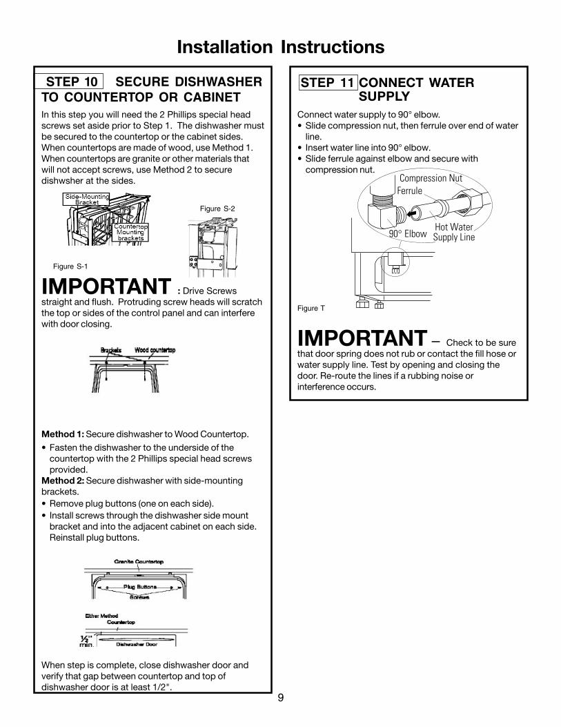
STEP 10 SECURE DISHWASHERTO COUNTERTOP OR CABINETIn this step you will need the 2 Phillips special headscrews set aside prior to Step 1. The dishwasher mustbe secured to the countertop or the cabinet sides.When countertops are made of wood, use Method 1.When countertops are granite or other materials thatwill not accept screws, use Method 2 to securedishwsher at the sides.
IMPORTANT : Drive Screwsstraight and flush. Protruding screw heads will scratchthe top or sides of the control panel and can interferewith door closing.
Method 1: Secure dishwasher to Wood Countertop.
• Fasten the dishwasher to the underside of thecountertop with the 2 Phillips special head screwsprovided.
Method 2: Secure dishwasher with side-mountingbrackets.• Remove plug buttons (one on each side).
When step is complete, close dishwasher door andverify that gap between countertop and top ofdishwasher door is at least 1/2".
• Install screws through the dishwasher side mountbracket and into the adjacent cabinet on each side.Reinstall plug buttons.
STEP 11 CONNECT WATERSUPPLY
Ferrule
90° Elbow
Compression Nut
Hot WaterSupply Line
Connect water supply to 90° elbow.• Slide compression nut, then ferrule over end of water
line.• Insert water line into 90° elbow.• Slide ferrule against elbow and secure with
compression nut.
IMPORTANT – Check to be surethat door spring does not rub or contact the fill hose orwater supply line. Test by opening and closing thedoor. Re-route the lines if a rubbing noise orinterference occurs.
Figure T
Figure S-2
Figure S-1
10
Installation Instructions
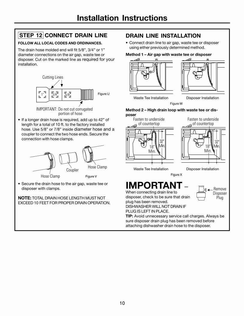
DRAIN LINE INSTALLATION• Connect drain line to air gap, waste tee or disposer
using either previously determined method.
Waste Tee Installation Disposer Installation
Method 2 – High drain loop with waste tee or dis-poser
IMPORTANT –When connecting drain line todisposer, check to be sure that drainplug has been removed.DISHWASHER WILL NOT DRAIN IFPLUG IS LEFT IN PLACE.TIP: Avoid unnecessary service call charges. Always besure disposer drain plug has been removed beforeattaching dishwasher drain hose to the disposer.
Cutting Lines
1" 3/4" 5/8"
IMPORTANT: Do not cut corrugated portion of hose
Fasten to undersideof countertop
32"Min.18"
Min.
Fasten to undersideof countertop
18"Min.
Hose ClampCoupler
Hose Clamp
RemoveDisposer
Plug
STEP 12 CONNECT DRAIN LINEFOLLOW ALL LOCAL CODES AND ORDINANCES.
The drain hose molded end will fit 5/8”, 3/4” or 1”diameter connections on the air gap, waste tee ordisposer. Cut on the marked line as required for yourinstallation.
Figure U
Figure V
• If a longer drain hose is required, add up to 42” oflength for a total of 10 ft. to the factory installedhose. Use 5/8” or 7/8” inside diameter hose and acoupler to connect the two hose ends. Secure theconnection with hose clamps.
• Secure the drain hose to the air gap, waste tee ordisposer with clamps.
NOTE: TOTAL DRAIN HOSE LENGTH MUST NOTEXCEED 10 FEET FOR PROPER DRAIN OPERATION.
Method 1 – Air gap with waste tee or disposer
Figure W
Waste Tee Installation Disposer Installation
Figure X
11
Installation Instructions
STEP 14 PRE-TEST CHECKLISTReview this list after installing yourdishwasher to avoid charges for a servicecall that is not covered by your warranty.
¨ Check to be sure power is OFF.
¨ Open door and remove all foam and paperpackaging.
¨ Locate the Owner’s Manual in the literature package.
¨ Read the Owner’s Manual for operating instructions.
¨ Check door opening and closing. If door does notopen and close freely or tends to fall, check springadjustments. See Step 1.
¨ Check to be sure that wiring is secure under thedishwasher, not pinched or in contact with doorsprings or other components. See Step 9.
¨ Check door alignment with tub. If door hits tub, leveldishwasher. See Step 10.
¨ Pull lower rack out, about half way. Check to be sureit does not roll back or forward on the door. If therack moves, adjust leveling legs. See Step 10.
¨ Check door alignment with cabinet. If door hitscabinet, reposition or relevel dishwasher. See Step10.
¨ Verify water supply and drain lines are not kinked orin contact with other components. Contact withmotor or dishwasher frame could cause noise. SeeStep 8.
¨ Turn on the sink hot water faucet and verify watertemperature. Incoming water temperature must bebetween 120°F and 150°F. A minimum of 120°Ftemperature is required for best wash performance.See "Prepare Hot Water Line", page 5.
¨ Add 2 quarts of water to the bottom of thedishwasher to lubricate the pump seal.
¨ Turn on water supply. Check for leaks. Tightenconnections if needed.
¨ Remove protective film if present from the controlpanel and door.
STEP 13 CONNECT POWERSUPPLY
Skip this step if equipped with power cord.Verify that power is turned off at the source.
• Remove junction box cover “A”.• Locate the three dishwasher wires, (white, black and
green) with stripped ends. Insert dishwasher wiresthrough the small hole in the junction box “B”.
• Secure house wiring to the bottom of the junction boxwith a strain relief “C”.
• User wire nuts to connect incoming ground to green,white to white and black to black “D”.
• Replace junction box cover “E”. Check to be surethat wires are not pinched under the cover.
WARNINGIf house wiring is not 2-wire withground, a ground must be providedby the installer. When house wiringis aluminum, be sure to use ULListed anti-oxidant compound andaluminum-to-copper connectors.

Installation Instructions
• Place 2-piece toekick against the legs of thedishwasher.
• Place the inner toekick piece (with slots) against thetoekick bracket. The slots should align with toekickbracket screw holes. Allow the toekick to touch thefloor.
• Place larger toekick over the inner piece and install 4toekick screws.
• Use additional 2 screws that are provided forinstallations over 33-1/2” high.
• Use both toekick pieces for all installation heights.
Figure Y
STEP 16 REPLACE TOEKICKSTEP 15 DISHWASHER WET TEST¨ Turn on power supply (or plug power cord into outlet,
if equipped).
¨ Turn dial to Normal “Wash” position.
¨ Close door.
¨ Check to be sure that water enters the dishwasher.If water does not enter the dishwasher, check to besure that water and power are turned on.
¨ Check for leaks under the dishwasher. If a leak isfound, turn power supply off, then tightenconnections. Restore power after leak is corrected.
¨ Check for leaks around the door. A leak around thedoor could be caused by door rubbing or hittingagainst adjacent cabinetry. Reposition thedishwasher if necessary. See Step 9.
¨ The dishwasher will drain and turn off about 5 to 7minutes after the first fill. Check drain lines. If leaksare found, turn power off at the breaker and correctplumbing as necessary. Restore power aftercorrections are made. See Step 12.
¨ Open dishwasher door and make sure most of thewater has drained. If not, check that disposer plughas been removed and/or air gap is not plugged.See Step 13. Also check drain line for kinking.
¨ Run the dishwasher through another fill and draincycle. Check for leaks and correct if required.
¨ At the end of drain, open door and turn dial to OFFposition.
STEP 17 LITERATUREBe sure to leave complete literature package andinstallation instructions with consumer.
2-Piece ToekickAdjust Upor Down
Use Top 4Screw Holes