Embed Size (px)
Citation preview
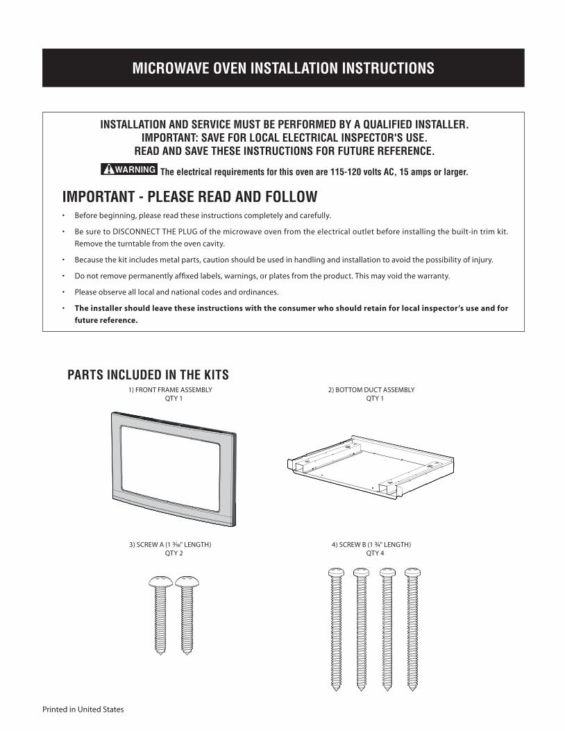
MICROWAVE OVEN INSTALLATION INSTRUCTIONS
INSTALLATION AND SERVICE MUST BE PERFORMED BY A QUALIFIED INSTALLER.IMPORTANT: SAVE FOR LOCAL ELECTRICAL INSPECTOR'S USE.
READ AND SAVE THESE INSTRUCTIONS FOR FUTURE REFERENCE.
The electrical requirements for this oven are 115-120 volts AC, 15 amps or larger.
Printed in United States
IMPORTANT - PLEASE READ AND FOLLOW• Before beginning, please read these instructions completely and carefully.
• Be sure to DISCONNECT THE PLUG of the microwave oven from the electrical outlet before installing the built-in trim kit.
Remove the turntable from the oven cavity.
• Because the kit includes metal parts, caution should be used in handling and installation to avoid the possibility of injury.
• Do not remove permanently affixed labels, warnings, or plates from the product. This may void the warranty.
• Please observe all local and national codes and ordinances.
• The installer should leave these instructions with the consumer who should retain for local inspector’s use and for
future reference.
PARTS INCLUDED IN THE KITS 1) FRONT FRamE aSSEmBLy
QTy 12) BOTTOm DUCT aSSEmBLy
QTy 1
3) SCREw a (1 ³₁₆" LENGTH) QTy 2
4) SCREw B (1 ³₄" LENGTH) QTy 4
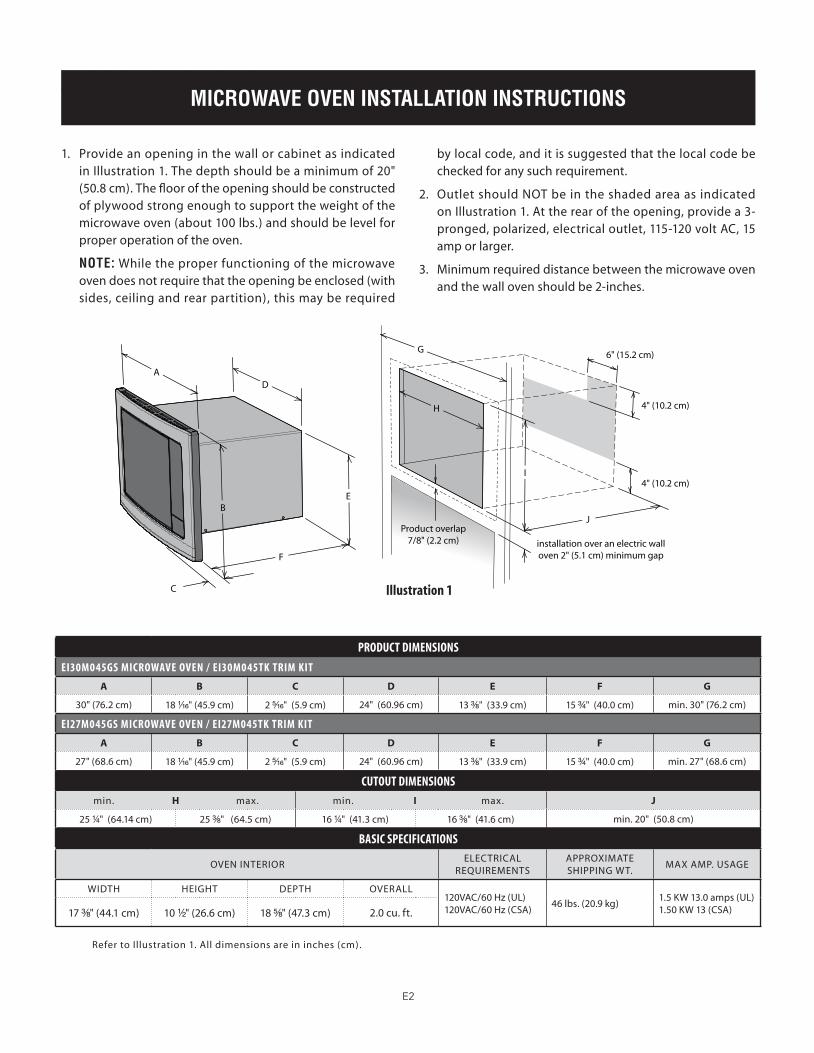
MICROWAVE OVEN INSTALLATION INSTRUCTIONS
#490_EHP VBA installation.indd 1 1/10/08 1:09:37 PM
E2
MICROWAVE OVEN INSTALLATION INSTRUCTIONSBASIC SPECIFICATIONS
Refer to Illustration 1. all dimensions are in inches (cm).
Illustration 1
1. Provide an opening in the wall or cabinet as indicated in Illustration 1. The depth should be a minimum of 20" (50.8 cm). The floor of the opening should be constructed of plywood strong enough to support the weight of the microwave oven (about 100 lbs.) and should be level for proper operation of the oven.
NOTE: while the proper functioning of the microwave oven does not require that the opening be enclosed (with sides, ceiling and rear partition), this may be required
by local code, and it is suggested that the local code be checked for any such requirement.
2. Outlet should NOT be in the shaded area as indicated on Illustration 1. at the rear of the opening, provide a 3-pronged, polarized, electrical outlet, 115-120 volt aC, 15 amp or larger.
3. minimum required distance between the microwave oven and the wall oven should be 2-inches.
A
B
C
D
E
F
6" (15.2 cm)
4" (10.2 cm)
4" (10.2 cm)
installation over an electric walloven 2" (5.1 cm) minimum gap
H
G
Product overlap7/8" (2.2 cm)
I
J
PRODUCT DIMENSIONS
EI30M045GS MICROwavE OvEN / EI30M045TK TRIM KIT
A B C D E F G
30" (76.2 cm) 18 ¹₁₆" (45.9 cm) 2 ⁵₁₆" (5.9 cm) 24" (60.96 cm) 13 ³₈" (33.9 cm) 15 ³₄" (40.0 cm) min. 30" (76.2 cm)
EI27M045GS MICROwavE OvEN / EI27M045TK TRIM KIT
A B C D E F G
27" (68.6 cm) 18 ¹₁₆" (45.9 cm) 2 ⁵₁₆" (5.9 cm) 24" (60.96 cm) 13 ³₈" (33.9 cm) 15 ³₄" (40.0 cm) min. 27" (68.6 cm)
CUTOUT DIMENSIONS
min. H max. min. I max. J
25 ¹₄" (64.14 cm) 25 ³₈" (64.5 cm) 16 ¹₄" (41.3 cm) 16 ³₈" (41.6 cm) min. 20" (50.8 cm)
BaSIC SPECIFICaTIONS
OVEN INTERIORELECTRICaL
REQUIREmENTSaPPROxImaTE SHIPPING wT.
max amP. USaGE
wIDTH HEIGHT DEPTH OVERaLL120VaC/60 Hz (UL)120VaC/60 Hz (CSa)
46 lbs. (20.9 kg)1.5 Kw 13.0 amps (UL)1.50 Kw 13 (CSa)17 ³₈" (44.1 cm) 10 ¹⁄₂" (26.6 cm) 18 ⁵₈" (47.3 cm) 2.0 cu. ft.
#490_EHP VBA installation.indd 2 1/10/08 1:09:39 PM

Illustration 1
E3
MICROWAVE OVEN INSTALLATION INSTRUCTIONS
BOTTOM DUCT ASSEMBLY1. Place the bottom duct in the opening and center. when
the Bottom Duct assembly is in the opening correctly, the flange will be tight against the lower edge of the opening. See Illustration 2.
Illustration 2 Illustration 3
Illustration 4 Illustration 5
SCREw aSCREw a
2. Secure the Bottom Duct assembly with the two (1 ³₁₆") screws a. IMPORTANT: Secure screws to the inside cabinet. See Illustration 3.
UNIT INSTALLATION1. Place the oven adjacent to the wall or cabinet opening.
Plug the power cord into the electrical outlet. Carefully guide the oven into the prepared opening. Slide the oven on the Bottom Duct assembly. avoid pinching the cord between the oven and the wall. adjust the position of the oven so that it will rest on the Bottom Duct assembly, but not fully pushed in. See Illustration 4.
2. Locate tabs on the built in trim kit to the slots on control panel. Snap the built in trim kit into the control panel to lock in place. See Illustration 5.
SHaPE ON BOTTOm
#490_EHP VBA installation.indd 3 1/10/08 1:09:42 PM
MICROWAVE OVEN INSTALLATION INSTRUCTIONS
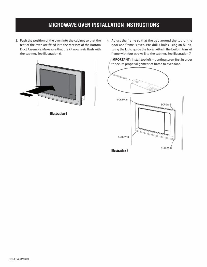
3. Push the position of the oven into the cabinet so that the feet of the oven are fitted into the recesses of the Bottom Duct assembly. make sure that the kit now rests flush with the cabinet. See Illustration 6.
Illustration 6
Illustration 7
SCREw B
SCREw B
SCREw B
SCREw B
4. adjust the frame so that the gap around the top of the door and frame is even. Pre-drill 4 holes using an ¹⁄₈" bit, using the kit to guide the holes. attach the built-in trim kit frame with four screws B to the cabinet. See Illustration 7.
IMPORTANT: Install top left mounting screw first in order to secure proper alignment of frame to oven face.
TINSEB490mRR1
#490_EHP VBA installation.indd 4 1/10/08 1:09:45 PM
S1
INSTRUCCIONES DE INSTALACIÓN DEL HORNO MICROONDAS
LA INSTALACIÓN Y EL SERVICIO DEBEN SER REALIZADOS POR UN INSTALADOR CALIFICADO.IMPORTANTE: GUARDE PARA USO DEL INSPECTOR ELÉCTRICO LOCAL. LEA Y GUARDE ESTAS INSTRUCCIONES PARA REFERENCIA FUTURA.
ADVERTENCIA Los requisitos eléctricos de este horno son de 115-120 voltios de CA, 15 amperios o más.
Impreso en los Estados Unidos
IMPORTANTE - LEA Y SIGA LAS INSTRUCCIONES• antes de comenzar, lea estas instrucciones completa y detalladamente.
• asegúrese de DESCONECTaR el horno microondas del tomacorriente eléctrico antes de instalar el juego de moldura para
empotrado. Retire el plato giratorio de la cavidad del horno.
• El juego incluye partes de metal por lo que debe manipularlo e instalarlo con precaución para evitar el riesgo de lesiones.
• No retire las etiquetas, advertencias o placas permanentes del producto. Esto puede anular la garantía.
• Cumpla todos los códigos y normas locales y nacionales.
• El instalador debe devolver estas instrucciones al cliente quien debe conservarlas para uso del inspector local y para
referencias futuras.
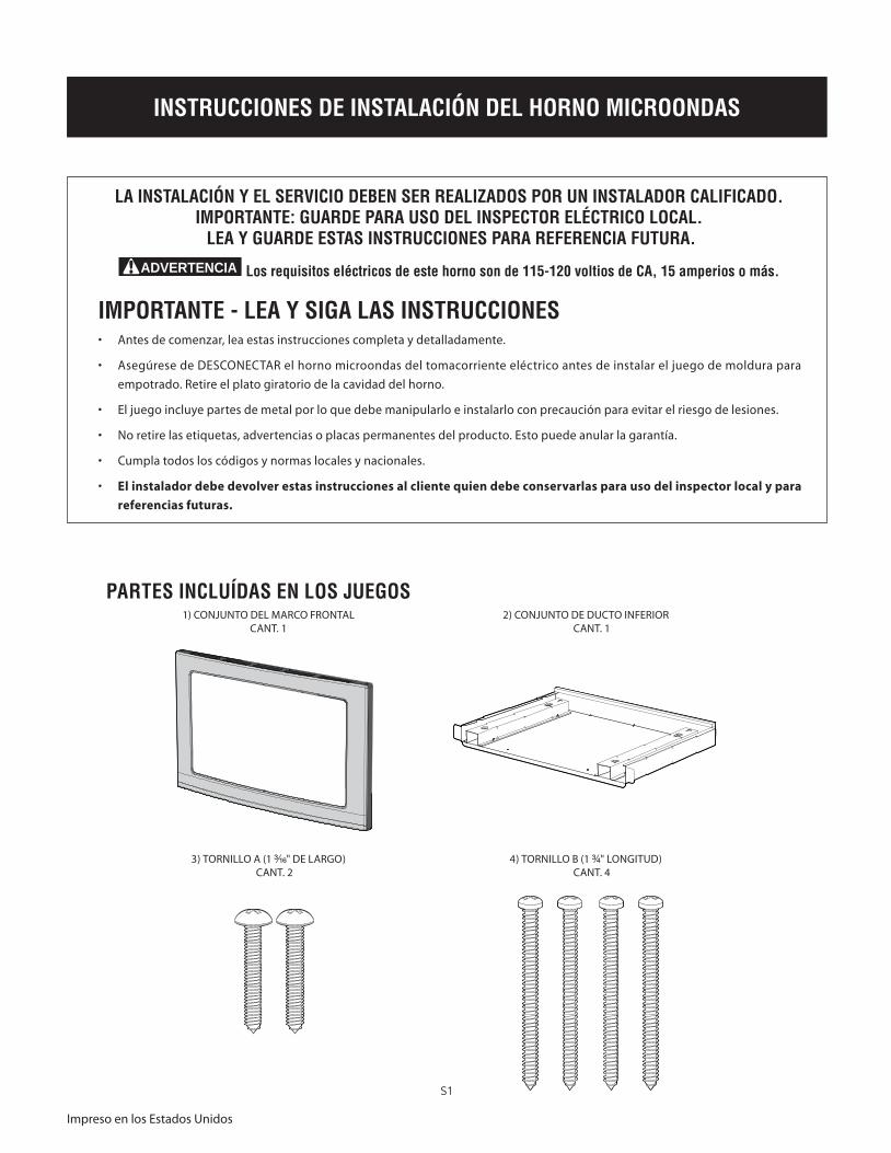
PARTES INCLUÍDAS EN LOS JUEGOS 1) CONjUNTO DEL maRCO FRONTaL
CaNT. 12) CONjUNTO DE DUCTO INFERIOR
CaNT. 1
3) TORNILLO a (1 ³₁₆" DE LaRGO) CaNT. 2
4) TORNILLO B (1 ³₄" LONGITUD) CaNT. 4
INSTRUCCIONES DE INSTALACIÓN DEL HORNO MICROONDAS
#490_EHP VBA installation.indd 1 1/10/08 1:09:48 PM
S2
INSTRUCCIONES DE INSTALACIÓN DEL HORNO MICROONDAS
A
B
C
D
E
F
6" (15.2 cm)
4" (10.2 cm)
4" (10.2 cm)
Instalación sobre un horno eléctrico depared separación mínima de 2" (5.1 cm)
H
G
Colocacióndel producto7/8" (2.2 cm)
I
J
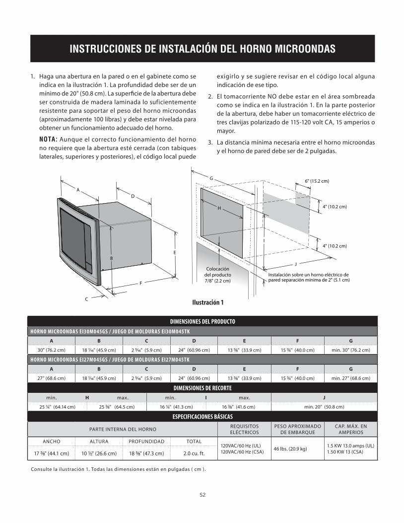
BASIC SPECIFICATIONS
Consulte la ilustración 1. Todas las dimensiones están en pulgadas ( cm ) .
Ilustración 1
1. Haga una abertura en la pared o en el gabinete como se indica en la ilustración 1. La profundidad debe ser de un mínimo de 20" (50.8 cm). La superficie de la abertura debe ser construida de madera laminada lo suficientemente resistente para soportar el peso del horno microondas (aproximadamente 100 libras) y debe estar nivelada para obtener un funcionamiento adecuado del horno.
NOTA: aunque el correcto funcionamiento del horno no requiere que la abertura esté cerrada (con tabiques laterales, superiores y posteriores), el código local puede
exigirlo y se sugiere revisar en el código local alguna indicación de ese tipo.
2. El tomacorriente NO debe estar en el área sombreada como se indica en la ilustración 1. En la parte posterior de la abertura, debe haber un tomacorriente eléctrico de tres clavijas polarizado de 115-120 volt Ca, 15 amperios o mayor.
3. La distancia mínima necesaria entre el horno microondas y el horno de pared debe ser de 2 pulgadas.
DIMENSIONES DEL PRODUCTO
HORNO MICROONDaS EI30M045GS / JUEGO DE MOLDURaS EI30M045TK
A B C D E F G
30" (76.2 cm) 18 ¹₁₆" (45.9 cm) 2 ⁵₁₆" (5.9 cm) 24" (60.96 cm) 13 ³₈" (33.9 cm) 15 ³₄" (40.0 cm) min. 30" (76.2 cm)
HORNO MICROONDaS EI27M045GS / JUEGO DE MOLDURaS EI27M045TK
A B C D E F G
27" (68.6 cm) 18 ¹₁₆" (45.9 cm) 2 ⁵₁₆" (5.9 cm) 24" (60.96 cm) 13 ³₈" (33.9 cm) 15 ³₄" (40.0 cm) min. 27" (68.6 cm)
DIMENSIONES DE RECORTE
min. H max. min. I max. J
25 ¹₄" (64.14 cm) 25 ³₈" (64.5 cm) 16 ¹₄" (41.3 cm) 16 ³₈" (41.6 cm) min. 20" (50.8 cm)
ESPECIFICaCIONES BÁSICaS
PaRTE INTERNa DEL HORNOREQUISITOS ELÉCTRICOS
PESO aPROxImaDO DE EmBaRQUE
CaP. mÁx. EN amPERIOS
aNCHO aLTURa PROFUNDIDaD TOTaL120VaC/60 Hz (UL)120VaC/60 Hz (CSa)
46 lbs. (20.9 kg)1.5 Kw 13.0 amps (UL)1.50 Kw 13 (CSa)17 ³₈" (44.1 cm) 10 ¹⁄₂" (26.6 cm) 18 ⁵₈" (47.3 cm) 2.0 cu. ft.
#490_EHP VBA installation.indd 2 1/10/08 1:09:51 PM
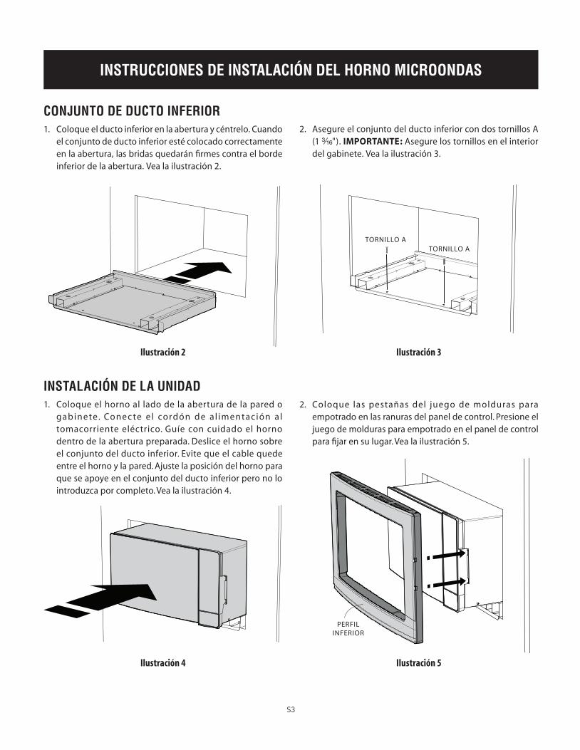
Illustration 1
S3
INSTRUCCIONES DE INSTALACIÓN DEL HORNO MICROONDAS
CONJUNTO DE DUCTO INFERIOR1. Coloque el ducto inferior en la abertura y céntrelo. Cuando
el conjunto de ducto inferior esté colocado correctamente en la abertura, las bridas quedarán firmes contra el borde inferior de la abertura. Vea la ilustración 2.
Ilustración 2 Ilustración 3
Ilustración 4 Ilustración 5
TORNILLO aTORNILLO a
2. asegure el conjunto del ducto inferior con dos tornillos a (1 ³₁₆"). IMPORTANTE: asegure los tornillos en el interior del gabinete. Vea la ilustración 3.
INSTALACIÓN DE LA UNIDAD1. Coloque el horno al lado de la abertura de la pared o
gabinete. Conec te e l cordón de a l imentac ión a l tomacorriente eléctrico. Guíe con cuidado el horno dentro de la abertura preparada. Deslice el horno sobre el conjunto del ducto inferior. Evite que el cable quede entre el horno y la pared. ajuste la posición del horno para que se apoye en el conjunto del ducto inferior pero no lo introduzca por completo. Vea la ilustración 4.
2. Coloque las pestañas del juego de molduras para empotrado en las ranuras del panel de control. Presione el juego de molduras para empotrado en el panel de control para fijar en su lugar. Vea la ilustración 5.
PERFIL INFERIOR
#490_EHP VBA installation.indd 3 1/10/08 1:09:53 PM
S4
INSTRUCCIONES DE INSTALACIÓN DEL HORNO MICROONDAS
3. Empuje el horno dentro del gabinete para que las patas del horno encajen en las ranuras del conjunto de ducto inferior. asegúrese de que el juego esté nivelado con el gabinete. Vea la ilustración 6.
Ilustración 6
Ilustración 7
TORNILLO B
TORNILLO B
TORNILLO B
TORNILLO B
4. ajuste el marco de modo que el espacio alrededor de la puerta y el marco sea uniforme. Pre-taladre 4 agujeros usando una broca de ¹⁄₈", usando el juego para guiar la posición de los agujeros. Fije el juego de molduras para empotrado al gabinete con cuatro tornillos B. Vea la ilustración 7.
IMPORTANTE: Instale primero el tornillo de montaje de la parte superior izquierda, para asegurar un alineamiento correcto del marco hacia la parte frontal del horno.
TINSEB490mRR1
#490_EHP VBA installation.indd 4 1/10/08 1:09:57 PM

F1
DIRECTIVES D’INSTALLATION DU FOUR À MICRO-ONDES
UN INSTALLATEUR QUALIFIÉ DOIT PROCÉDER À L’INSTALLATION ET AUX RÉPARATIONS.IMPORTANT : CONSERVER À L’USAGE D’UN INSPECTEUR EN ÉLECTRICITÉ LOCAL.
LIRE ET CONSERVER CES DIRECTIVES POUR RÉFÉRENCE FUTURE.
AVERTISSEMENT L’alimentation électrique pour ce four est de 115-120 volts CA, 15 ampères et plus.
Imprimé aux États-Unis
IMPORTANT - PRIÈRE DE LIRE ET DE SUIVRE• Prière de lire attentivement toutes ces directives avant de commencer.
• Veiller à DÉBRaNCHER La FICHE du four à micro-ondes de la prise électrique avant d’installer la garniture à encastrer. Retirer la table tournante de la cavité du four.
• Le kit comprend des parties métalliques, il faut faire attention lors de la manipulation et de l’installation pour éviter éventuelles blessures.
• Ne pas retirer de façon permanente les étiquettes, les mises en garde ou les plaques fixées au produit. Cela pourrait annuler la garantie.
• Veuillez observer tous les codes et règlements locaux et national.
• L’installateur devra laisser ces directives au client qui devra les conserver pour l’usage d’un inspecteur local et pour référence ultérieure.
PIÈCES FOURNIES AVEC LES KITS 1) ENSEmBLE DU CHâSSIS aVaNT
QTÉ 12) ENSEmBLE DU CONDUIT INFÉRIEUR
QTÉ 1
3) VIS a (LONGUEUR 1 ³₁₆ po) QTÉ 2
4) VIS B (LONGUEUR 1 ³₄ po) QTÉ 4
#490_EHP VBA installation.indd 1 1/10/08 1:10:01 PM
F2
DIRECTIVES D’INSTALLATION DU FOUR À MICRO-ONDES
A
B
C
D
E
F
15,2 cm (6 po)
10,2 cm (4 po)
10,2 cm (4 po)
Installation au dessus d'un four électrique,espacement minimal 5,1 cm (2 po).
H
G
Chevauchementdu produit
2,2 cm (7/8 po)
I
J
BASIC SPECIFICATIONS
Voir illustration 1. Toutes les dimensions sont en centimètres (po).
Illustration 1
1. Faire une ouverture dans le mur ou l’armoire comme indiqué à l ’illustration 1. La profondeur doit être au minimum de 50,8 cm (20 po). Le plancher de l’ouverture doit être en contreplaqué assez fort pour sup porter le poids du four et sa propre charge (environ 45,5 kg [100 lb]) et doit être à un niveau convenable pour l’utilisation du four.
NOTE: Bien que le bon fonctionnement du four ne demande pas que l’ouverture soit close (avec cloisons
latérales, arrière et plafond); le code local pourrait l’exiger; il est donc suggéré de vérifier ce point.
2. La prise NE doit PaS se trouver dans l’aire ombrée comme indiqué à l’Illustration 1.À l’arrière de l’ouverture, installer une prise électrique polarisée pour fiche à trois broches, 115-120 volt Ca, 15 a ou plus.
3. La distance minimale exigée entre le four à micro-ondes et le four mural doit être de 5,1 cm (2 po).
DIMENSIONS DU PRODUIT
FOUR à MICRO-ONDES EI30M045GS / KIT DE GaRNITURE EI30M045TK
A B C D E F G
76,2 cm (30 po) 45,9 cm (18 ¹₁₆ po) 5,9 cm (2 ⁵₁₆ po) 60,96 cm (24 po) 33,9 cm (13 ³₈ po) 40,0 cm (15 ³₄ po) min. 76,2 cm (30 po)
FOUR à MICRO-ONDES EI27M045GS / KIT DE GaRNITURE EI27M045TK
A B C D E F G
68,6 cm (27 po) 45,9 cm (18 ¹₁₆ po) 5,9 cm (2 ⁵₁₆ po) 60,96 cm (24 po) 33,9 cm (13 ³₈ po) 40,0 cm (15 ³₄ po) min. 68,6 cm (27 po)
DIMENSIONS DE La DÉCOUPE
min. H max. min. I max. J
64,14 cm (25 ¹₄ po) 64,5 cm (25 ³₈ po) 41,3 cm (16 ¹₄ po) 41,6 cm (16 ³₈ po) min. 50,8 cm (20 po)
SPÉCIFICaTIONS DE BaSE
INTÉRIEUR DU FOURaLImENTaTION
ÉLECTRIQUEPOIDS aPPROx. À
L’ExPÉDITIONamPÉRaGE max.
USaGE
LaRGEUR HaUTEUR PROFONDEUR HORS TOUT120V Ca/60 Hz (UL)120V Ca/60 Hz (CSa)
46 lb (20,9 kg)1,5 Kw 13,0 amps (UL)1,50 Kw 13 (CSa)44,1 cm (17 ³₈ po) 26,6 cm (10 ¹⁄₂ po) 47,3 cm (18 ⁵₈ po) 0,04 m3 (2 pi3)
#490_EHP VBA installation.indd 2 1/10/08 1:10:03 PM
Illustration 1
F3
DIRECTIVES D’INSTALLATION DU FOUR À MICRO-ONDES
1. Placer le conduit inférieur dans l’ouverture et centrer. Quand il est placé correctement, les brides seront serrées contre la bordure inférieure de l’ouverture. Voir Illustration 2.
Illustration 2 Illustration 3
Illustration 4 Illustration 5
VIS a
VIS a
2. Fixer l’ensemble du conduit inférieur avec deux vis a (1 ³₁₆ po). IMPORTANT: Bien fixer les vis à l’intérieur de l’armoire. Voir Illustration 3.
INSTALLATION DE L’APPAREIL1. Placer le four près de l’ouverture du mur ou de l’armoire.
Brancher le cordon d’alimentation dans la prise électrique. Guider avec précaution le four assemblé dans l’ouverture préparée. Faire glisser le four sur l’ensemble du conduit inférieur. Éviter de pincer le cordon entre le four et le mur. ajuster la position du four afin qu’il repose sur l’ensemble du conduit inférieur d’évacuation, mais pas complètement poussé dans l’armoire. Voir Illustration 4.
2. mettre les languettes du kit de garniture à encastrer en face des fentes du panneau de commande. Enclencher le kit de garniture à encastrer dans le panneau de commande pour le verrouiller en place. Voir Illustration 5.
FORmE À La BaSE
ENSEMBLE DU CONDUIT INFÉRIEUR D’ÉVACUATION
#490_EHP VBA installation.indd 3 1/10/08 1:10:06 PM

F4
DIRECTIVES D’INSTALLATION DU FOUR À MICRO-ONDES
3. Pousser le four dans l’armoire afin que ses pattes entrent dans les évidements de l’ensemble du conduit inférieur d’évacuation. Vérifier alors que le kit soit affleurant à l’armoire. Voir Illustration 6.
Illustration 6
Illustration 7
VIS B
VIS B
VIS B
VIS B
4. ajuster le châssis afin que l’espacement au sommet de la porte et le châssis soit à égalité. Percer 4 avant-trous avec un foret de ¹⁄₈, à l’aide du kit pour guider les trous. Fixer le châssis du kit de garniture à encastrer avec 4 vis B. Voir Illustration 7.
IMPORTANT : Installer la vis de fixation supérieure gauche afin d’aligner correctement le châssis sur la façade du four.
TINSEB490mRR1
#490_EHP VBA installation.indd 4 1/10/08 1:10:10 PM
MICROWAVE OVEN INSTALLATION INSTRUCTIONS
A
B
C
D
E
F
6" (15.2 cm)
4" (10.2 cm)
4" (10.2 cm)
installation over an electric walloven 2" (5.1 cm) minimum gap
H
G
Product overlap7/8" (2.2 cm)
I
J
*
TCADHB078MRR0
INSTRUCCIONES DE INSTALACIÓN DEL HORNO MICROONDAS
DIRECTIVES D’INSTALLATION DU FOUR À MICRO-ONDES
CORRECTION page F2: Dimension D*
DIMENSIONS DU PRODUIT
FOUR à MIcRO-ONDES EI30M045GS / KIT DE GaRNITURE EI30M045TK
A B C D* E F G
76,2 cm(30 po)
45,9 cm(18 ¹₁₆ po)
5,9 cm(2 ⁵₁₆ po)
60,96 cm(24 po)
33,9 cm(13 ³₈ po)
40,0 cm(15 ³₄ po)
min. 76,2 cm (30 po)
FOUR à MIcRO-ONDES EI27M045GS / KIT DE GaRNITURE EI27M045TK
A B C D* E F G
68,6 cm(27 po)
45,9 cm (18 ¹₁₆ po)
5,9 cm(2 ⁵₁₆ po)
60,96 cm(24 po)
33,9 cm(13 ³₈ po)
40,0 cm(15 ³₄ po)
min. 68,6 cm (27 po)
CORRECCIÓN página S2: Dimensión D*
DIMENSIONES DEL PRODUcTO
HORNO MIcROONDaS EI30M045GS / JUEGO DE MOLDURaS EI30M045TK
A B C D* E F G
30"(76.2 cm)
18 ¹₁₆"(45.9 cm)
2 ⁵₁₆"(5.9 cm)
24"(60.96 cm)
13 ³₈"(33.9 cm)
15 ³₄"(40.0 cm)
min. 30" (76.2 cm)
HORNO MIcROONDaS EI27M045GS / JUEGO DE MOLDURaS EI27M045TK
A B C D* E F G
27"(68.6 cm)
18 ¹₁₆"(45.9 cm)
2 ⁵₁₆"(5.9 cm)
24"(60.96 cm)
13 ³₈"(33.9 cm)
15 ³₄"(40.0 cm)
min. 27" (68.6 cm)
CORRECTION page E2: Dimension D*
PRODUcT DIMENSIONS
EI30M045GS MIcROwavE OvEN / EI30M045TK TRIM KIT
A B C D* E F G
30"(76.2 cm)
18 ¹₁₆"(45.9 cm)
2 ⁵₁₆"(5.9 cm)
24"(60.96 cm)
13 ³₈"(33.9 cm)
15 ³₄"(40.0 cm)
min. 30" (76.2 cm)
EI27M045GS MIcROwavE OvEN / EI27M045TK TRIM KIT
A B C D* E F G
27"(68.6 cm)
18 ¹₁₆"(45.9 cm)
2 ⁵₁₆"(5.9 cm)
24"(60.96 cm)
13 ³₈"(33.9 cm)
15 ³₄"(40.0 cm)
min. 27" (68.6 cm)