Embed Size (px)
Citation preview
Installation and Operating instructions for
Economy built-in Panel PC CP62x9-xxxx-0020
Version: 1.0 Date: 2019-09-09


Foreword
Table of contents
1.
2.
3.
4.
Foreword 3 Notes on the Documentation 3
Liability Conditions 3 Trademarks 3 Patent Pending 3 Copyright 3 State at Delivery 3 Delivery conditions 3
Description of safety symbols 4 Basic safety measures 5 Operator’s obligation to exercise diligence 6 Operator requirements 6
Product Description 7 Appropriate Use 7 Interfaces 7
DVI (Digital Visual Interface) 7 USB-Interfaces 7 Network connection 7 Power supply 7 Ground connection 7 Access to the CF-Card and the Battery 8
Installation Instructions 9 Transport and Unpacking 9
Transport 9 Unpacking 9
Installation of the PC in the control cabinet 10 Installation in a control cabinet wall 10 Earthing measures 10 Mounting of the Panel PC 11
Power Supply Connection 12 Beckhoff power supply technology 12 Pin assignment of the connector 13
Fitting the cable 14 Material for assembling the connectors 14 Assembling the connectors 14
Connecting Power Supply 15 Cable Cross Sections 15 Configuration for shutting down the PC 15 PC_ON and Power Status functions 15 UPS output 15 UPS output function 15 Wiring diagram 16
Connecting devices 17 Connecting cables 17 Check voltage rating and connect 17
Operating Instructions 18 Switching the Industrial PC on and off 18
First switching on and driver installation 18 Operation 18 Keyboard codes 19 Servicing and maintenance 21
Cleaning the Industrial PC 21 Replacing the battery on the motherboard 21 Servicing 21
Emergency procedures 21 Shutting down 21
Disposal 21
CP62x9-xxxx-0020 1
Foreword
5.
6.
7.
UPS Software Components (optional) 22 Installation on the PC 22 Help files 22
Troubleshooting 23 Fault correction 23 Beckhoff Support & Service 24
Beckhoff branches and partner companies 24 Beckhoff Headquarters 24 Beckhoff Support 24 Beckhoff Service 24
Appendix 25 Assembly dimensions 25
Built-in Panel PC CP6209-000x-0020 25 Built-in Panel PC CP6219-000x-0020 26 Built-in Panel PC CP6229-000x-0020 27
Technical data 28 Approvals 28
FCC: Federal Communications Commission Radio Frequency Interference Statement 28 FCC: Canadian Notice 28
2 CP62x9-xxxx-0020
Foreword
Foreword Notes on the Documentation This description is only intended for the use of trained specialists in control and automation engineering who are familiar with the applicable national standards. It is essential that the following notes and explanations are followed when installing and commissioning these components. The responsible staff must ensure that the application or use of the products described satisfy all the requirements for safety, including all the relevant laws, regulations, guidelines and standards.
Liability Conditions The documentation has been prepared with care. The products described are, however, constantly under development. For that reason the documentation is not in every case checked for consistency with performance data, standards or other characteristics. In the event that it contains technical or editorial errors, we retain the right to make alterations at any time and without warning. No claims for the modification of products that have already been supplied may be made on the basis of the data, diagrams and descriptions in this documentation.
All pictures shown in the documentation are exemplary. Illustrated configurations can differ from standard.
Trademarks Beckhoff®, TwinCAT®, EtherCAT®, Safety over EtherCAT®, TwinSAFE®, XFC® and XTS® are registered trademarks of and licensed by Beckhoff Automation GmbH. Other designations used in this publication may be trademarks whose use by third parties for their own purposes could violate the rights of the owners.
Patent Pending The EtherCAT Technology is covered, including but not limited to the following patent applications and patents: EP1590927, EP1789857, DE102004044764, DE102007017835 with corresponding applications or registrations in various other countries. The TwinCAT Technology is covered, including but not limited to the following patent applications and patents: EP0851348, US6167425 with corresponding applications or registrations in various other countries.
Copyright © Beckhoff Automation GmbH & Co.KG. The reproduction, distribution and utilization of this document as well as the communication of its contents to others without express authorization are prohibited. Offenders will be held liable for the payment of damages. All rights reserved in the event of the grant of a patent, utility model or design.
State at Delivery All the components are supplied in particular hardware and software configurations appropriate for the application. Modifications to hardware or software configurations other than those described in the documentation are not permitted, and nullify the liability of Beckhoff Automation GmbH & Co.KG.
Delivery conditions In addition, the general delivery conditions of the company Beckhoff Automation GmbH & Co.KG apply.
CP62x9-xxxx-0020 3
Foreword
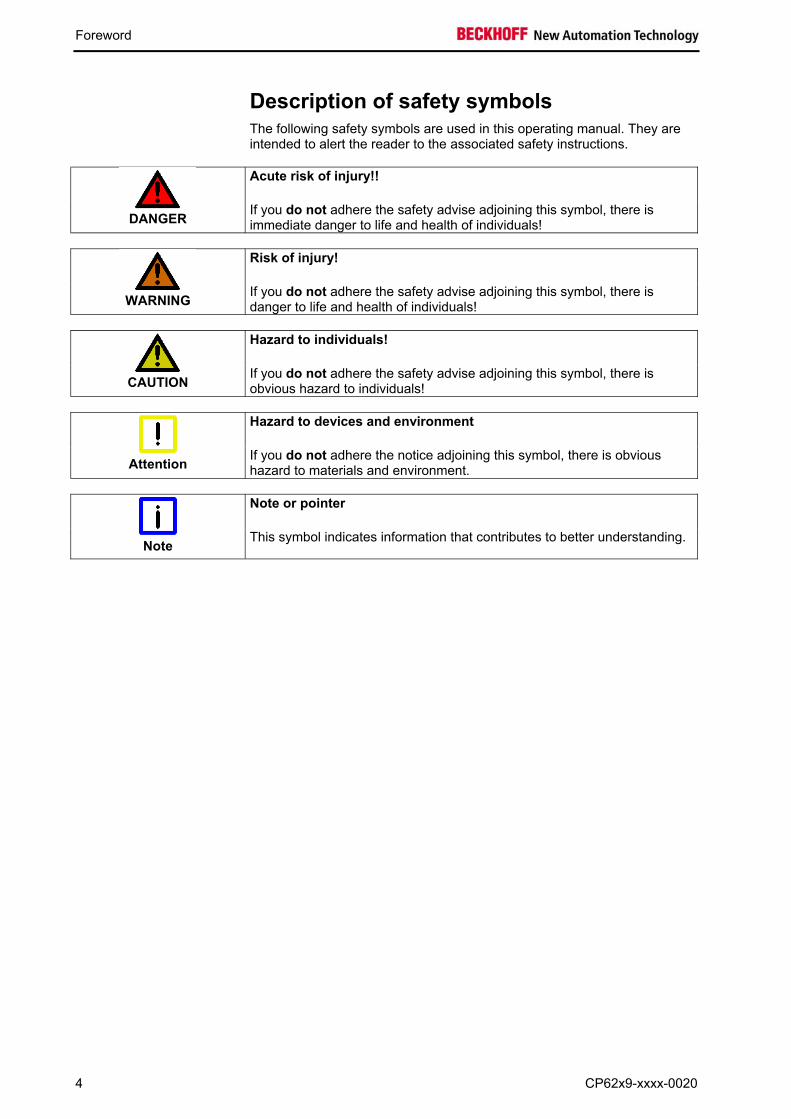
Description of safety symbols The following safety symbols are used in this operating manual. They are
intended to alert the reader to the associated safety instructions. Acute risk of injury!!
DANGER If you do not adhere the safety advise adjoining this symbol, there is
immediate danger to life and health of individuals!
Risk of injury!
WARNING If you do not adhere the safety advise adjoining this symbol, there is
danger to life and health of individuals!
Hazard to individuals!
CAUTION If you do not adhere the safety advise adjoining this symbol, there is
obvious hazard to individuals!
Hazard to devices and environment
Attention If you do not adhere the notice adjoining this symbol, there is obvious
hazard to materials and environment.
Note or pointer
Note This symbol indicates information that contributes to better understanding.
4 CP62x9-xxxx-0020
Foreword
Basic safety measures Only switch the PC off after closing the software
Before the Industrial PC is switched off, software that is running must be properly closed. Otherwise it is possible that data on the storage medium is lost. Please read the section Switching the Industrial PC on and off. Switch off all parts of the equipment, then uncouple the fieldbus
Attention
Before opening the housing of the PC, and whenever the PC is being used for purposes other than plant control, such as during functional tests following repair, all parts of the equipment must first be switched off, after which the Industrial PC can be uncoupled from the plant.
Pulling out the fieldbus connection plug uncouples the PC (optional).
Items of equipment that have been switched off must be secured against being switched on again.
The Industrial PC’s power supply unit must be supplied with 24VDC.
Do not open the power supply unit while voltage is applied!
CAUTION The supply voltage must be switched off before the power supply unit
housing is opened.
Do not exchange any parts when under power
Attention
When components are being fitted or removed, the supply voltage must be switched off.
Fitting work on the Industrial PC can result in damage: • if metal objects such as screws or tools fall onto operating circuit
boards. • if connecting cables internal to the PC are removed or inserted
during operation. • if plug-in cards are removed or inserted when the PC is switched
on.
High Voltage!
DANGER
Displays used for the control panel’s LC-display are operated with a voltage of up to 1000 V, depending on type. For that reason: The supply voltage must be disconnected before the housing of the Control Panel is opened.
CP62x9-xxxx-0020 5

Foreword
Operator’s obligation to exercise diligence The operator must ensure that
• the Industrial PC is only used for its intended purpose (see chapter Product Description).
• the Industrial PC is only operated in a sound condition and in working order (see chapter Servicing and maintenance).
• the Industrial PC is operated, maintained and repaired only by suitably qualified and authorized personnel.
• the personnel is instructed regularly about relevant occupational safety and environmental protection aspects, and is familiar with the operating manual and in particular the safety notes contained herein.
• the instruction manual is in good condition and complete, and always available for reference at the place of installation of the Industrial PC.
• none of the safety and warning notes attached to the Industrial PC are removed, and all notes remain legible.
• every user is familiar with all the functions of the software installed on the Industrial PC to which he has access.
National regulations depending on the machine type
Depending on the type of machine and plant in which the Industrial PC is used, national regulations governing the controllers of such machines will apply, and must be observed by the operator. These regulations cover, amongst other things, the intervals between inspections of the controller. The operator must initiate such inspections in good time. Do not open the housing of the build-in Panel PC
Note
For technical support contact Beckhoff Service.
Procedure in the event of a fault
In the event of faults at the Industrial PC, the list in the section Troubleshooting can be used to determine the measures to be taken.
Operator requirements
Read the operating instructions
Anyone who uses the Industrial PC must have read these operating instructions.
Software knowledge Every user must be familiar with all the functions of the software installed on the Industrial PC to which he has access.
6 CP62x9-xxxx-0020

Product Description
Product Description Appropriate Use The CP62x9-xxxx-0020 build-in Panel PC is designed for industrial
application in machine and plant engineering. A steel plate housing with aluminum front contains a TFT display, touch screen (optional) and a keyboard (optional). The Industrial PC is installed in the front of control cabinets.
Do not use the Build-in Panel PC in areas of explosive hazard
The build-in Panel PC must not be used where there is a risk of explosion.
Interfaces Interfaces
DVI (Digital Visual Interface) X103 DVI out
The DVI connection is used for transferring the video signal. DVI-D standard is supported.
USB-Interfaces X104 – X107 USB out
The four USB interfaces are used for connecting peripheral devices with USB connection. USB2.0 standard is supported.
Network connection X108 LAN1
The RJ-45 connector allows the PC to be connected to a 10/100/1000BASE-T Local Area Network (LAN).
X109 LAN2
The RJ-45 connector allows the PC to be connected to a 10/100/1000BASE-T Local Area Network (LAN).
Power supply X110 Power
The power supply for the Industrial PC is established via the socket.
Ground connection Ground connection The Industrial PC is grounded via the stud bolt.
CP62x9-xxxx-0020 7
Product Description
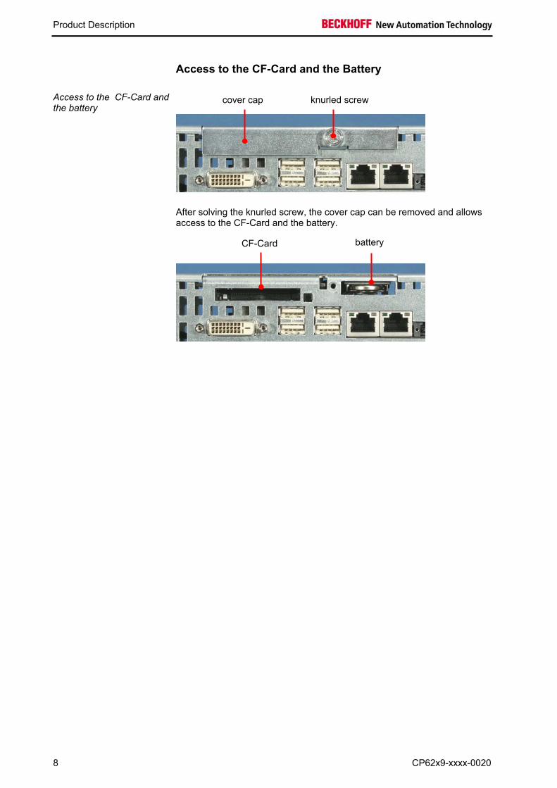
Access to the CF-Card and the Battery
Access to the CF-Card and the battery
After solving the knurled screw, the cover cap can be removed and allows access to the CF-Card and the battery.
knurled screw cover cap
battery CF-Card
8 CP62x9-xxxx-0020
Installation Instructions
Installation Instructions
Transport and Unpacking The specified storage conditions must be observed (see chapter Technical
data).
Transport Despite the robust design of the unit, the components are sensitive to
strong vibrations and impacts. During transport, your Control Panel should therefore be protected from excessive mechanical stress. Therefore, please use the original packaging.
Danger of damage to the unit
Attention
If the device is transported in cold weather or is exposed to extreme variations in temperature, make sure that moisture (condensation) does not form on or inside the device.
Prior to operation, the unit must be allowed to slowly adjust to room temperature. Should condensation occur, a delay time of approximately 12 hours must be allowed before the unit is switched on.
Unpacking
Proceed as follows to unpack the unit:
1. Remove packaging. 2. Do not discard the original packaging. Keep it for future relocation. 3. Check the delivery for completeness by comparing it with your order. 4. Please keep the associated paperwork. It contains important
information for handling the unit. 5. Check the contents for visible shipping damage. 6. If you notice any shipping damage or inconsistencies between the
contents and your order, you should notify Beckhoff Service.
CP62x9-xxxx-0020 9

Installation Instructions
Installation of the PC in the control cabinet The built-in Panel PC CP62x9-xxxx-0020 is designed for mounting in
control cabinets in machine and plant engineering applications. The ambient conditions specified for operation must be observed (see chapter Technical data).
Preparation of the control cabinet
The control cabinet wall must be prepared with the required mounting opening for the computer unit according to the PC’s dimensions (see chapter Assembly dimensions). Circulation of air
Note
When the unit is installed in an enclosure, adequate space for ventilation and for opening the PC must be provided.
The clearance above and below the housing must be at least 5 cm in order to ensure adequate ventilation of the PC.
Please note the following points during installation of the PC:
• Position the PC in such a way that reflections on the screen are
avoided as far as possible. • Use the position of the screen as a guide for the correct installation
height; it should be optimally visible for the user at all times. • The PC should not be exposed to direct sunlight. • When the unit is in its mounting position, the ventilation openings must
not be obstructed. Avoid extreme environmental conditions
Attention
Extreme environmental conditions should be avoided as far as possible. Protect the PC from dust, moisture and heat.
The ventilation slots of the PC must not be covered.
Installation in a control cabinet wall Installation in a control cabinet wall
Proceed as follows: 1. Insert the PC at the intended control cabinet wall position and protect it
from falling out, prior to final mounting.
2. Release the clamping levers, turn the clamping levers to the side and retighten the screws (see chapter Mounting of the Panel PC).
Earthing measures
Earthing measures
Earthing connections dissipate interference from external power supply cables, signal cables or cables to peripheral equipment.
Establish a low-impedance connection from the
earthing point on the PC housing to the central earthing point on the control cabinet wall, in which the computer is being installed.
10 CP62x9-xxxx-0020
Installation Instructions
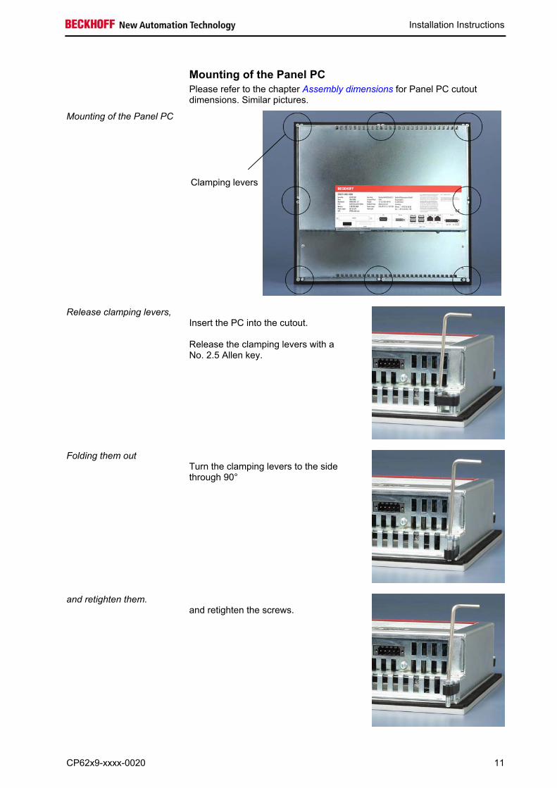
Mounting of the Panel PC Please refer to the chapter Assembly dimensions for Panel PC cutout
dimensions. Similar pictures.
Mounting of the Panel PC
Clamping levers
Release clamping levers,
Insert the PC into the cutout. Release the clamping levers with a No. 2.5 Allen key.
Folding them out
Turn the clamping levers to the side through 90°
and retighten them.
and retighten the screws.
CP62x9-xxxx-0020 11
Installation Instructions
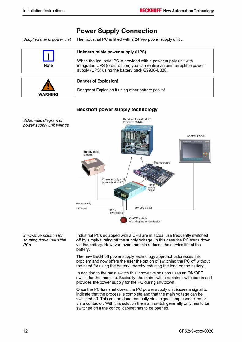
Power Supply Connection Supplied mains power unit The Industrial PC is fitted with a 24 VDC power supply unit .
Uninterruptible power supply (UPS)
Note
When the Industrial PC is provided with a power supply unit with integrated UPS (order option) you can realize an uninterruptible power supply (UPS) using the battery pack C9900-U330.
Danger of Explosion!
WARNING
Danger of Explosion if using other battery packs!
Beckhoff power supply technology Schematic diagram of power supply unit wirings
Innovative solution for shutting down Industrial PCs
Industrial PCs equipped with a UPS are in actual use frequently switched off by simply turning off the supply voltage. In this case the PC shuts down via the battery. However, over time this reduces the service life of the battery.
The new Beckhoff power supply technology approach addresses this problem and now offers the user the option of switching the PC off without the need for using the battery, thereby reducing the load on the battery.
In addition to the main switch this innovative solution uses an ON/OFF switch for the machine. Basically, the main switch remains switched on and provides the power supply for the PC during shutdown.
Once the PC has shut down, the PC power supply unit issues a signal to indicate that the process is complete and that the main voltage can be switched off. This can be done manually via a signal lamp connection or via a contactor. With this solution the main switch generally only has to be switched off if the control cabinet has to be opened.
12 CP62x9-xxxx-0020
Installation Instructions
In order to maintain a screen display for the Industrial PC in the event of a
power failure, the power supply unit is equipped with a UPS output for connecting a Control Panel. This enables a power failure to be visualized and displayed to the user. Once the PC has shut down, the UPS output is switched off in order to avoid total discharge of the battery.
For a detailed functional description please refer to chapter Connecting Power Supply.
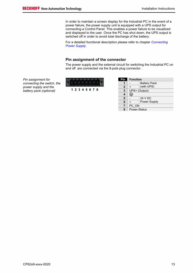
Pin assignment of the connector The power supply and the external circuit for switching the Industrial PC on
and off are connected via the 8-pole plug connector .
Pin assignment for connecting the switch, the power supply and the battery pack (optional)
Pin Function 1 - 2 +
Battery Pack (with UPS)
3 UPS+ (Output) 4 5 - 6 +
24 V DC Power Supply
7 PC_ON 8 Power-Status
1 2 3 4 5 6 7 8
CP62x9-xxxx-0020 13
Installation Instructions
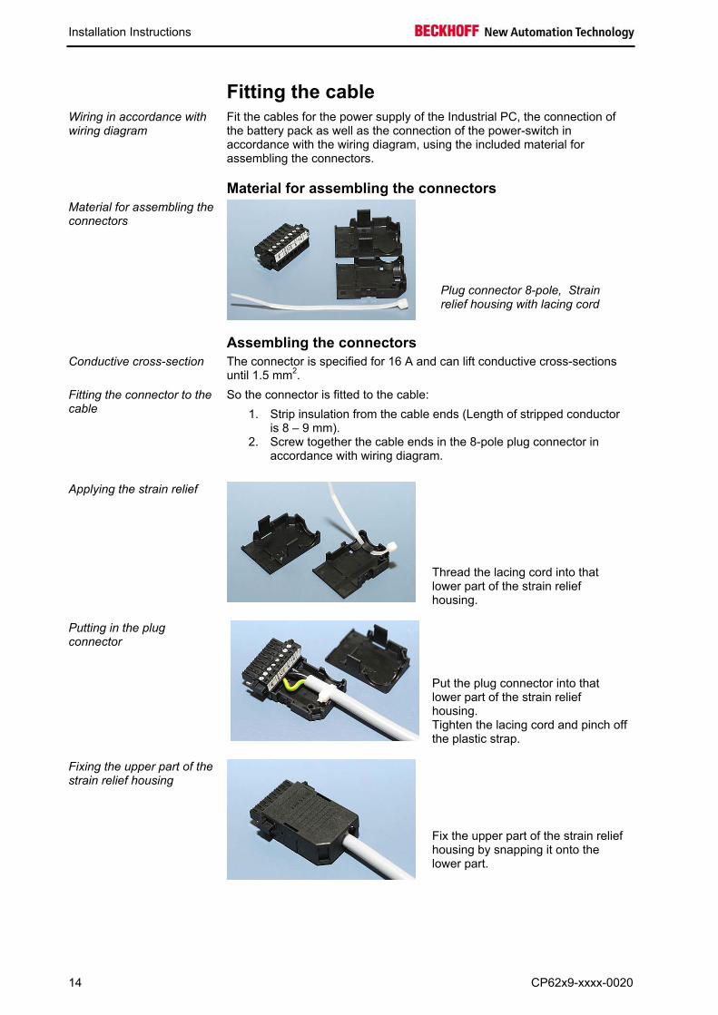
Fitting the cable Wiring in accordance with wiring diagram
Fit the cables for the power supply of the Industrial PC, the connection of the battery pack as well as the connection of the power-switch in accordance with the wiring diagram, using the included material for assembling the connectors.
Material for assembling the connectors Material for assembling the connectors
Plug connector 8-pole, Strain relief housing with lacing cord
Assembling the connectors Conductive cross-section The connector is specified for 16 A and can lift conductive cross-sections
until 1.5 mm2.
Fitting the connector to the cable
So the connector is fitted to the cable:
1. Strip insulation from the cable ends (Length of stripped conductor is 8 – 9 mm).
2. Screw together the cable ends in the 8-pole plug connector in accordance with wiring diagram.
Applying the strain relief
Thread the lacing cord into that lower part of the strain relief housing.
Putting in the plug connector
Put the plug connector into that lower part of the strain relief housing. Tighten the lacing cord and pinch off the plastic strap.
Fixing the upper part of the strain relief housing
Fix the upper part of the strain relief housing by snapping it onto the lower part.
14 CP62x9-xxxx-0020
Installation Instructions
Connecting Power Supply The external wiring consists of the connection of the power supply, the
battery pack (optional) and the connection of customized components for shutting down the PC.
Cable Cross Sections
Note cable cross sections, avoid voltage drop!
For the connection of the power supply, wiring with a cable-cross-section of 1.5 mm2 must be used.
With bigger distances between voltage source and PC, you take the voltage drop as a function of the cable-cross-section as well as voltage fluctuations of your distribution voltage into account, so that is secured that the voltage doesn't fall under 22 V at the power supply.
Insert fuse
Attention
The power supply must be protected with maximum 16 A.
Configuration for shutting down the PC The connections for shutting down the Industrial PCs are established via
the PC_ON input and the Power Status output.
PC_ON and Power Status functions
• If the PC_ON input is connected to 24 V via a switch, the PC shuts down according to the rules. The PC_ON signal is inverted, i.e. the PC shuts down if the 24 V connection is live.
• If the PC_ON input is NOT connected by the user, the PC can be booted in the familiar way by connecting the supply voltage and shut down via the battery by switching off the supply voltage.
Service life of the rechargeable battery
Attention
This procedure significantly reduces the service life of the rechargeable battery and should therefore not be used.
• Once the PC has shut down, the Power Status output is switched
from 24 V to 0 V. Via this output a signal lamp can be connected or a contactor for de-energizing the whole system. The maximum load for the Power Status output is 0.5 A and a suitable fuse should be provided.
UPS output
In order to maintain a screen display for the PC in the event of a power failure, the power supply unit is equipped with a UPS output for connecting a Control Panel. The maximum load for the output is 1.4 A.
UPS output function
• The 24 V DC connection at the UPS output is live even after a power failure. The maximum load is 1.4 A.
• Once the PC has been de-energized via the UPS software, the UPS output is switched to 0 V. Any connected panel is thus switched off, and total discharge of the rechargeable battery is prevented.
CP62x9-xxxx-0020 15
Installation Instructions
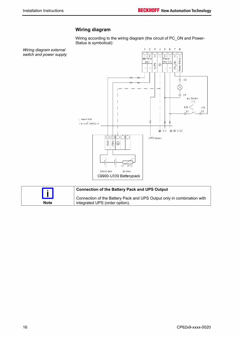
Wiring diagram Wiring according to the wiring diagram (the circuit of PC_ON and Power-
Status is symbolical):
Wiring diagram external switch and power supply
Connection of the Battery Pack and UPS Output
Note
Connection of the Battery Pack and UPS Output only in combination with integrated UPS (order option).
16 CP62x9-xxxx-0020
Connecting devices
Power supply plug
Attention
The power supply plug must be withdrawn!
Please read the documentation for the external devices prior to connecting them.
During thunderstorms, plug connector must neither be inserted nor removed.
When disconnecting a plug connector, always handle it at the plug. Do not pull the cable!
Connecting cables The connections are located at the top of the Industrial PC and are
documented in the product description chapter. When connecting the cables to the Industrial PC, proceed according to the following sequence:
• Switch off all the devices that are to be connected. • Disconnect all the devices that are to be connected from the power
supply. • Connect all the cables between the Industrial PC and to the
devices that are to be connected. • Connect all data transfer cables (if present) to the appropriate
plug-in receptacles of the data/telecommunication networks. • Reconnect all devices to the power supply.
Check voltage rating and connect Fitted with the 24 VDC power supply unit:
1. Check that the external power supply is providing the correct voltage.
2. Insert the power supply cable that you have assembled (see chapter Fitting the cable) into the Industrial PC's power supply socket. Then connect it to your external 24 V power supply.
Use same type of rechargeable battery
Attention
If a 24 V UPS is installed, the same type of rechargeable battery must be used.
CP62x9-xxxx-0020 17
Operating Instructions
Operating Instructions
Switching the Industrial PC on and off Switch on The Industrial PC does not have its own mains switch. The Industrial PC
will start when the equipment is switched on, or when it is connected to the power supply.
Shutting down and switching off
When the plant is switched off, or when it is disconnected from its power supply, the Industrial PC will be switched off. Control software such as is typically used on Industrial PCs permits various users to be given different rights. A user who may not close software may also not switch the Industrial PC off, since data can be lost from the storage medium by switching off while software is running.
First shut down, then switch off the PC
Attention
If the Industrial PC is switched off as the software is writing a file to the storage medium, the file will be destroyed. Control software typically writes something to the storage medium every few seconds, so that the probability of causing damage by switching off while the software is running is very high.
Switch off power supply
Attention
When you have shut down the Industrial PC, you have to switch off power supply for at least 10 seconds before rebooting the system. After resetting power supply the PC will start booting automatically.
First switching on and driver installation When you switch on the Industrial PC for the first time, the pre-installed
operating system (optional) will be started. In this case, all the required drivers for any additional, optional hardware components ordered with the PC will already have been installed. If the PC was ordered without operating system, you have to install the operating system and the driver software for any auxiliary hardware yourself. Please follow the instructions in the documentation for the operating system and the additional devices.
Operation The touch screen may only be actuated by fingertips or with the touch screen pen
Note
The touch screen may only be actuated by finger tips or with the touch screen pen. The operator may wear gloves but there must be no hard particles such as metal shavings, glass splinters embedded in the glove.
The Panel PC’s membrane keypad may only be actuated by fingertips
Note
Attempts to actuate it with other objects can easily result in the destruction of the device. Neither may the membrane keypad be operated with a touch screen pen.
18 CP62x9-xxxx-0020
Operating Instructions
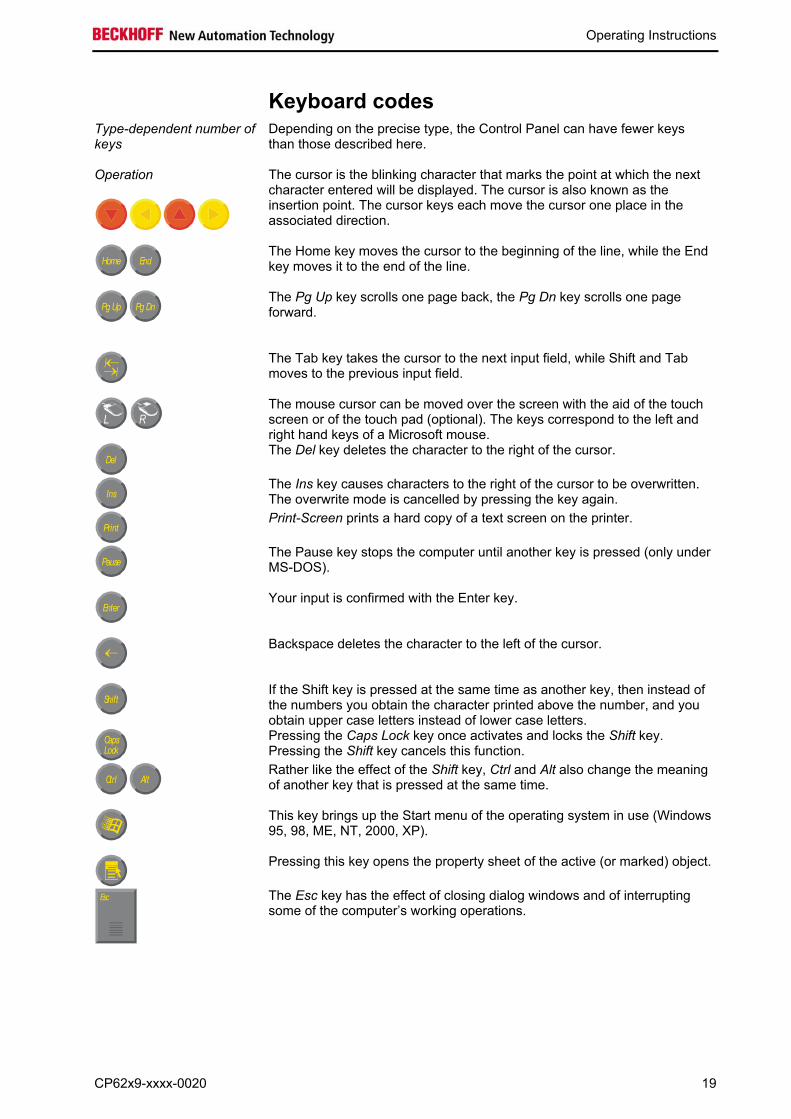
Keyboard codes Type-dependent number of keys
Depending on the precise type, the Control Panel can have fewer keys than those described here.
Operation
The cursor is the blinking character that marks the point at which the next character entered will be displayed. The cursor is also known as the insertion point. The cursor keys each move the cursor one place in the associated direction.
Home End
The Home key moves the cursor to the beginning of the line, while the End key moves it to the end of the line.
Pg Up Pg Dn
The Pg Up key scrolls one page back, the Pg Dn key scrolls one page forward.
The Tab key takes the cursor to the next input field, while Shift and Tab moves to the previous input field.
L R The mouse cursor can be moved over the screen with the aid of the touch screen or of the touch pad (optional). The keys correspond to the left and right hand keys of a Microsoft mouse.
Del
The Del key deletes the character to the right of the cursor.
Ins
The Ins key causes characters to the right of the cursor to be overwritten. The overwrite mode is cancelled by pressing the key again.
Print-Screen prints a hard copy of a text screen on the printer.
Pause
The Pause key stops the computer until another key is pressed (only under MS-DOS).
Enter
Your input is confirmed with the Enter key.
Backspace deletes the character to the left of the cursor.
Shift
If the Shift key is pressed at the same time as another key, then instead of the numbers you obtain the character printed above the number, and you obtain upper case letters instead of lower case letters.
CapsLock
Pressing the Caps Lock key once activates and locks the Shift key. Pressing the Shift key cancels this function.
Ctrl Alt
Rather like the effect of the Shift key, Ctrl and Alt also change the meaning of another key that is pressed at the same time.
This key brings up the Start menu of the operating system in use (Windows 95, 98, ME, NT, 2000, XP).
Pressing this key opens the property sheet of the active (or marked) object.
Esc
The Esc key has the effect of closing dialog windows and of interrupting some of the computer’s working operations.
CP62x9-xxxx-0020 19
Operating Instructions
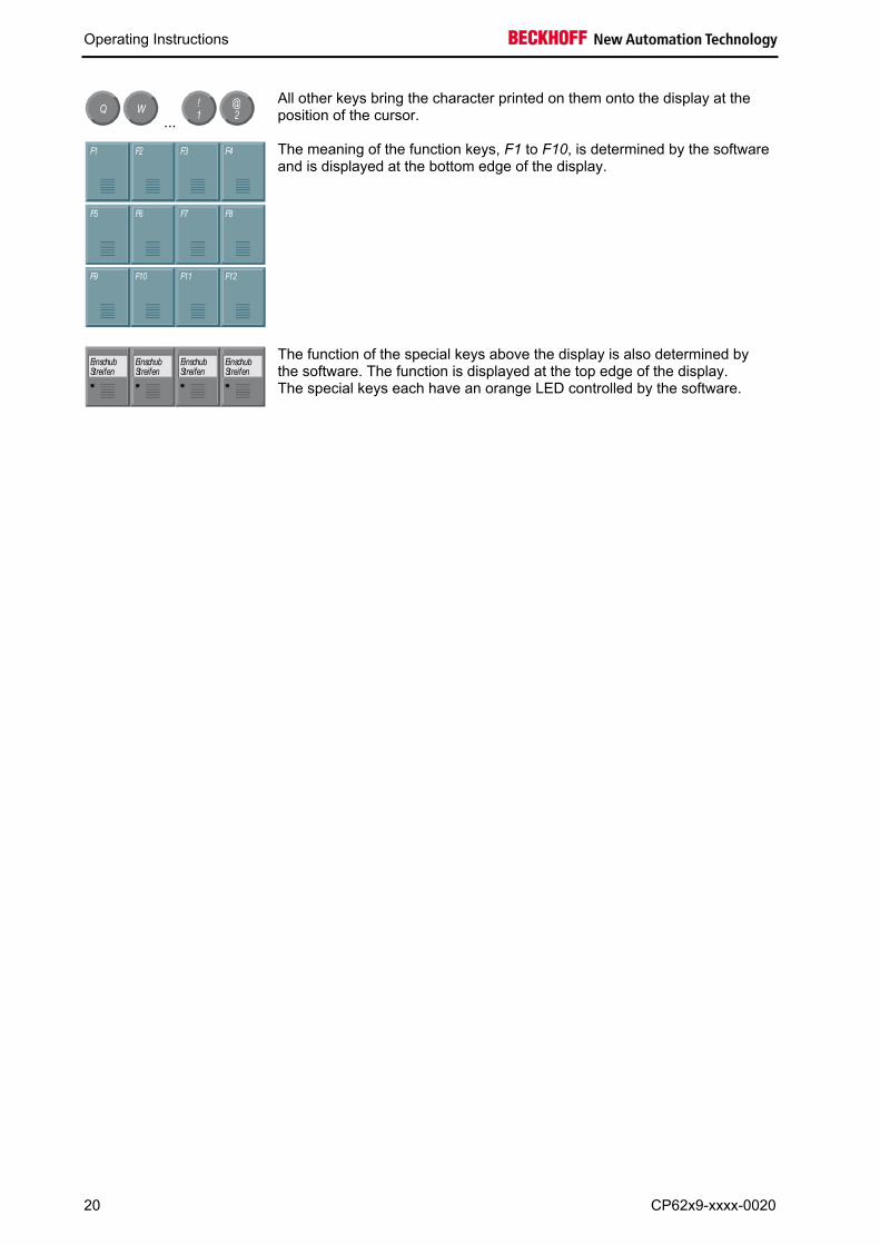
Q W ... 1
!2@
All other keys bring the character printed on them onto the display at the position of the cursor.
F1 F2 F3 F4
F5 F6 F7 F8
F9 F10 F11 F12
The meaning of the function keys, F1 to F10, is determined by the software and is displayed at the bottom edge of the display.
EinschubStreifen
EinschubStreifen
EinschubStreifen
EinschubStreifen
The function of the special keys above the display is also determined by the software. The function is displayed at the top edge of the display. The special keys each have an orange LED controlled by the software.
20 CP62x9-xxxx-0020
Operating Instructions
Servicing and maintenance
Cleaning the Industrial PC
Disconnect from power supply
Attention
Switch off the Industrial PC and all connected devices, and disconnect the Industrial PC from the power supply.
The Industrial PC can be cleaned with a soft, damp cloth. Do not use any
aggressive cleaning materials, thinners, scouring material or hard objects that could cause scratches.
The front of the Panel can be cleaned with a soft, damp cleaning cloth. Do
not use any aggressive cleaning materials, thinners, scouring material or hard objects that could cause scratches.
Replacing the battery on the motherboard
A used battery on the motherboard has to be replaced according to the rules of the board manufacturer. See also chapter Access to the CF-Card and the Battery. Danger of Explosion!
WARNING
Danger of Explosion if battery is incorrectly replaced. Replace only with same or equivalent type recommended by the manufacturer. Dispose of used batteries according to the manufacturer's instructions.
Servicing
The build-in Panel PC requires no maintenance.
Do not open the housing of the build-in Panel PC
Note
For technical support contact Beckhoff Service.
Emergency procedures In case of fire, the Industrial PC should be extinguished with powder or
nitrogen.
Shutting down Disposal Dismantle the Industrial PC Observe national electronics scrap regulations
The device must be fully dismantled in order to dispose of it. The housing can be sent for metal recycling. Electronic parts such as lamps and circuit boards must be disposed of in accordance with national electronics scrap regulations.
CP62x9-xxxx-0020 21
UPS Software Components (optional)
UPS Software Components (optional) Installing the UPS driver software
For operating the power supply unit as a UPS, the UPS driver software and the associated UPS driver must be installed on the Industrial PC. On delivery of the Beckhoff Industrial PC with operating system the software is already installed. Should the software not be installed on your PC, the drivers can be installed from the driver CD provided.
Installation on the PC
Installation To install the UPS driver software, execute file Beckhoff_UPS_vx.xx.xx.exe from the subdirectory of UPS\… from the CD provided on the Industrial PC (Driver-archive for the Industrial-PC, C9900-S700-xxxx).
The program is self-extracting and will guide the user through the installation routine.
Help files
Beckhoff Information System
The driver software comes with a detailed help function. The help files can be called up either directly from the configuration register by clicking the Help button, or under via Start > Programs > Beckhoff > UPS software components.
22 CP62x9-xxxx-0020
Troubleshooting
Troubleshooting
Pixel errors
Note
Pixel errors in the TFT display are production-caused and represent no complaint-reason!
Fault correction
Fault Cause Procedure
Nothing happens after the Industrial PC has been switched on
No power supply to the Industrial PC Other cause
Check power supply cable. Call Beckhoff Service
The Industrial PC does not boot fully
Setup settings are incorrect Other cause
Check the setup settings Call Beckhoff Service
Computer boots, software starts, but control does not operate correctly
Cause of the fault is either in the software or in parts of the plant outside the Industrial PC
Call the manufacturer of the machine or the software
CF-Card access error Faulty CF-Card Check CF-Card in another device Call Beckhoff Service
USB error while TwinCAT access via USB
Cycle time in TwinCAT is set on 10ms (standard)
Increase the cycle time up to 50ms till 80ms
The Industrial PC functions only partially or only part of the time, e.g. no or dark picture, but memory drive responds when switching on
Defective components in the Industrial PC
Call Beckhoff Service
CP62x9-xxxx-0020 23
Troubleshooting
Beckhoff Support & Service Beckhoff and their partners around the world offer comprehensive support
and service, guaranteeing fast and competent assistance with all questions related to Beckhoff products and system solutions.
Beckhoff branches and partner companies Please contact your Beckhoff branch office or partner company for local support and service on Beckhoff products!
The contact addresses for your country can be found in the list of Beckhoff branches and partner companies: www.beckhoff.com You will also find further documentation for Beckhoff components there.
Beckhoff Headquarters Beckhoff Automation GmbH & Co. KG Huelshorstweg 20 33415 Verl Germany Phone: +49(0)5246/963-0 Fax: +49(0)5246/963-198 e-mail: [email protected]
Beckhoff Support Beckhoff offers you comprehensive technical assistance, helping you not only with the application of individual Beckhoff products, but also with wide-ranging services:
• worldwide support • design, programming and commissioning of complex automation
systems • training program for Beckhoff system components
Hotline: +49(0)5246/963-157 Fax: +49(0)5246/963-9157 e-mail: [email protected]
Beckhoff Service The Beckhoff service center supports you in all matters of after-sales service:
• on-site service • repair service • spare parts service • hotline service
Hotline: +49(0)5246/963-460 Fax: +49(0)5246/963-479 e-mail: [email protected]
Quote the project number If servicing is required, please quote the project number of your product.
24 CP62x9-xxxx-0020

Appendix
Appendix
Assembly dimensions Built-in Panel PC CP6209-000x-0020
Notice mounting orientation
Attention
The assembly of the unit must take place with the orientation diagrammed here.
All dimensions are in mm.
installation depth front view
rear view with install measure
bottom view
rear view side view
CP62x9-xxxx-0020 25
Appendix
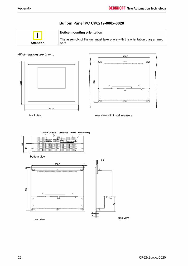
Built-in Panel PC CP6219-000x-0020
Notice mounting orientation
Attention
The assembly of the unit must take place with the orientation diagrammed here.
All dimensions are in mm.
front view rear view with install measure
bottom view
side view rear view
26 CP62x9-xxxx-0020
Appendix
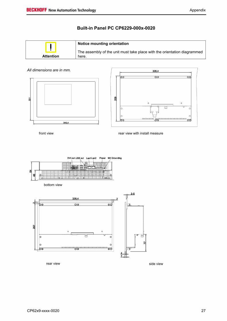
Built-in Panel PC CP6229-000x-0020
Notice mounting orientation
Attention
The assembly of the unit must take place with the orientation diagrammed here.
All dimensions are in mm.
front view rear view with install measure
bottom view
rear view side view
CP62x9-xxxx-0020 27
Appendix
28 CP62x9-xxxx-0020
Technical data Dimensions Dimensions (W x H x D): see chapter Assembly dimensions.
Operation in areas that are subject to explosion hazard
The Industrial PC must not be used where there is a risk of explosion.
The following conditions must be observed during operation: Environmental conditions Ambient temperature: 0 to 55°C
Atmospheric humidity: Maximum 95%, non-condensing
Shock resistance Sinusoidal vibration: (EN 60068-2-6) 10 to 58 Hz: 0.035 mm 58 to 500 Hz: 0.5 G (~ 5 m/ s2) Impact: (EN 60068-2-27) 5 G (~ 50 m/ s²), duration: 30 ms
Protection class Front side: IP65 Rear side: IP20
Power supply 24 VDC power pack
Supply voltage: 24 VDC (22 – 30 VDC) Power consumption: approx. 29 W
If operated with UPS: additional 30 W (while charging) additional 44 W (UPS-output max.)
EMC compatibility Resistance to interference: conforms to EN 61000-6-2
Emission of interference: conforms to EN 61000-6-4
Transport and storage The same values for atmospheric humidity and shock resistance are to be observed during transport and storage as in operation. Suitable packaging of the Industrial PC can improve the resistance to impact during transport. The ambient temperature during storage and transport must be between -20°C and +65°C.
Pixel errors
Note
Pixel errors in the TFT display are production-caused and represent no complaint-reason!
Approvals FCC: Federal Communications Commission
Radio Frequency Interference Statement FCC Approval for USA This equipment has been tested and found to comply with the limits for a
Class A digital device, pursuant to Part 15 of the FCC Rules. These limits are designed to provide reasonable protection against harmful interference when the equipment is operated in a commercial environment. This equipment generates, uses, and can radiate radio frequency energy and, if not installed and used in accordance with the instruction manual, may cause harmful interference to radio communications. Operation of this equipment in a residential area is likely to cause harmful interference in which case the user will be required to correct the interference at his own expense.
FCC: Canadian Notice FCC Approval for Canada This equipment does not exceed the Class A limits for radiated emissions
as described in the Radio Interference Regulations of the Canadian Department of Communications.