Embed Size (px)
Citation preview
Zip Hydroboil - Installation & Operating Instructions - 81447 - April 2013 v1.03 Page 1 of 12
Installation and Operating Instructions
Zip Hydroboil Instant boiling water
HS010 Hydroboil 10 Litre White 10552 HS110 Hydroboil 10 Litre Stainless Steel 10551HS015 Hydroboil 15 Litre White 11552HS115 Hydroboil 15 Litre Stainless Steel 11551HS025 Hydroboil 25 Litre White 12552HS125 Hydroboil 25 Litre Stainless Steel 12551HS040 Hydroboil 40 Litre White 04552HS140 Hydroboil 40 Litre Stainless Steel 04551
®
Zip Hydroboil - Installation & Operating Instructions - 81447 - April 2013 v1.03 Page 2 of 12
Installation Checklist
Description
Before Installation:
A. Read the instructions.
B. Note:Allfittingsaresuppliedwiththeappliancekitexceptisolationvalveand pressurereductionvalve,whicharenotsupplied.
C. Checkthewaterqualitytodetermineifextrafiltrationwillberequired.Apotable mainswatersupplymustbeused.
Tocombatthebuildupoflimescale,ahighperformanceinlinefilter(notsuppliedas standardequipment)maybeorderedfromyourZipserviceprovider.(SeeProduct Accessoriespage4)
D. Checktheapplianceratingplateandensurecorrectpowerisavailableforthe appliance.
E. Checkthewallsupportingtheapplianceisadequateforthetotalweightofthe appliance,whenfullofwater.
Before Commissioning:
1. Checktheunithasbeeninstalledcorrectly.
2. Checkallplumbingfittingshavebeentightened.
3. Ensure the vent pipe is positioned to drain correctly.
4. Checkallelectricalconnectionsarecorrectandtherearenoloosewires.
Commission:
7. Flush the supply line before connecting.
8. Turnonthewater,allowtofillandcheckforleaks.
9. Turnonthepower.
WallmountedOver-sinkapplianceforinstantboilingwater.
Features:• Designedtooperatewithin1°Cofboilingpoint.#
• Temperaturecontrolsautomaticallycutoffthepowerintheeventoftemperaturecontrolfailure,boildrycutoutorablockedventpipe.
• Incorporatingapulldowntapforprecisionfillingofcups,italsolocks‘ON’forfillingpots.
• Separatesthecoldwatersupplyfromtheboilingchamberandtheinternalcondensingsystemretainssteamwithintheheater.
• Astainlesssteelcrevicefree,boilingchamberwithserviceaccessportstopandbottom.
• Hightemperaturethermalinsulationwithprovisionforserviceaccesstotheboilingchamber.
• Concealedplumbingandelectricalconnections.
• Choiceofstainlesssteelorwhiteenamelledsteelcase.
Page 3 of 12 Zip Hydroboil - Installation & Operating Instructions - 81447 - April 2013 v1.03
Product Specifications / Accessories ...........................................................................................................................4
Read These Warnings First ..................................................................................................................................... 4 - 5
Installation Requirements .............................................................................................................................................5
Installation Procedures ........................................................................................................................................... 6 - 8
Step 1 – Positioning .................................................................................................................................6
Step 2 – Fastening ...................................................................................................................................6
Step 3 – Connecting ................................................................................................................................7
a)Plumbing ................................................................................................................................7
b)Venting...................................................................................................................................7
c)Electrical ................................................................................................................................7
Step4–Assembling ................................................................................................................................8
Tap Fitting ..................................................................................................................................8
Step5–Commissioning .........................................................................................................................8
Operating Procedures ..................................................................................................................................................8
Wall Mounting Template Dimensions ..........................................................................................................................9
Earth Continuity Verification / Wiring Diagram. ........................................................................................................10
Problem Solving...........................................................................................................................................................10
Maintenance ................................................................................................................................................................10
End of life disposal ......................................................................................................................................................10
Spare Parts ..................................................................................................................................................................11
Warranty / Contact Details ..........................................................................................................................................12
Contents
NOTE:
Read all instructions and precautions before proceeding. If in doubt, or need further guidance, please call Zip on 0845 6 005 005.
Pleaseleavetheseinstructionswiththeenduserafterinstallation.
Thisunitmustbeinstalledinaccordancewithwatersupplybyelaws,currentIEEregulationsandrelevantlocalauthoritybyelaws.
TheseproductsareapprovedtotheLVDandEMCdirectivesandCEendorsed.
ZipHydroboilhasbeenexamined,testedandfoundwhencorrectlyfittedtocomplywiththerequirementsoftheUnitedKingdomWaterRegulations/Byelaws(Scotland).TheproductsarelistedundertheWRAS(WaterRegulationsAdvisoryScheme)WaterFittingsandMaterialsDirectory.
ZipHeaters(UK)Ltdcannotbeheldliableforanydamagescausedbyfailuretoobservetheseinstructions.
Zip Hydroboil - Installation & Operating Instructions - 81447 - April 2013 v1.03 Page 4 of 12
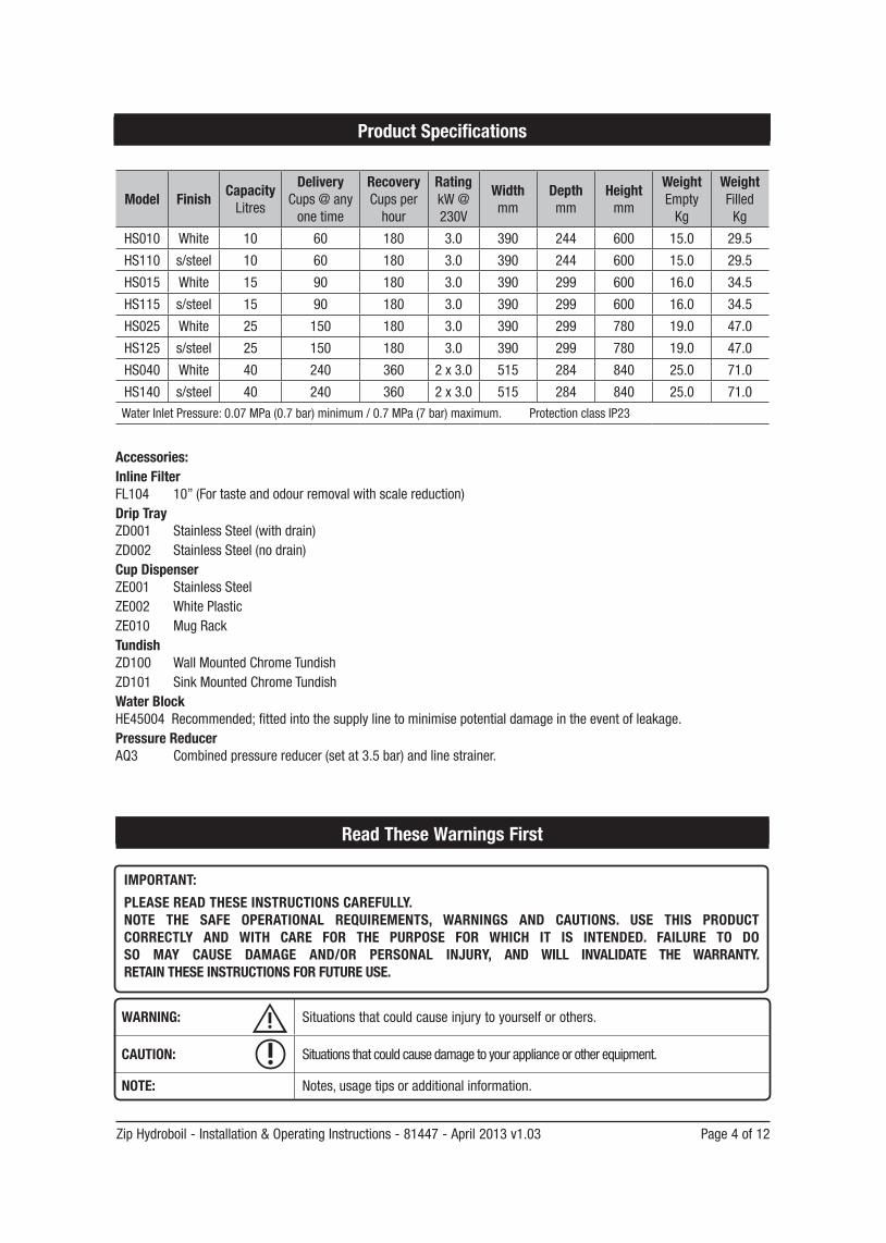
Accessories:Inline FilterFL104 10”(Fortasteandodourremovalwithscalereduction)Drip TrayZD001 StainlessSteel(withdrain)ZD002 StainlessSteel(nodrain)Cup DispenserZE001 Stainless SteelZE002 White PlasticZE010 MugRackTundishZD100 WallMountedChromeTundishZD101 SinkMountedChromeTundishWater BlockHE45004Recommended;fittedintothesupplylinetominimisepotentialdamageintheeventofleakage.Pressure ReducerAQ3 Combinedpressurereducer(setat3.5bar)andlinestrainer.
Read These Warnings First
WARNING: Situations that could cause injury to yourself or others.
CAUTION: Situationsthatcouldcausedamagetoyourapplianceorotherequipment.
NOTE: Notes,usagetipsoradditionalinformation.
IMPORTANT:
PLEASE READ THESE INSTRUCTIONS CAREFULLY. NOTE THE SAFE OPERATIONAL REQUIREMENTS, WARNINGS AND CAUTIONS. USE THIS PRODUCT CORRECTLY AND WITH CARE FOR THE PURPOSE FOR WHICH IT IS INTENDED. FAILURE TO DO SO MAY CAUSE DAMAGE AND/OR PERSONAL INJURY, AND WILL INVALIDATE THE WARRANTY. RETAIN THESE INSTRUCTIONS FOR FUTURE USE.
Model Finish CapacityLitres
DeliveryCups @ any onetime
RecoveryCups per
hour
RatingkW@230V
Widthmm
Depthmm
Heightmm
WeightEmpty
Kg
WeightFilled
Kg
HS010 White 10 60 180 3.0 390 244 600 15.0 29.5
HS110 s/steel 10 60 180 3.0 390 244 600 15.0 29.5
HS015 White 15 90 180 3.0 390 299 600 16.0 34.5
HS115 s/steel 15 90 180 3.0 390 299 600 16.0 34.5
HS025 White 25 150 180 3.0 390 299 780 19.0 47.0
HS125 s/steel 25 150 180 3.0 390 299 780 19.0 47.0
HS040 White 40 240 360 2x3.0 515 284 840 25.0 71.0
HS140 s/steel 40 240 360 2x3.0 515 284 840 25.0 71.0Water Inlet Pressure: 0.07MPa(0.7bar)minimum/0.7MPa(7bar)maximum. Protection class IP23
Product Specifications
Page 5 of 12 Zip Hydroboil - Installation & Operating Instructions - 81447 - April 2013 v1.03
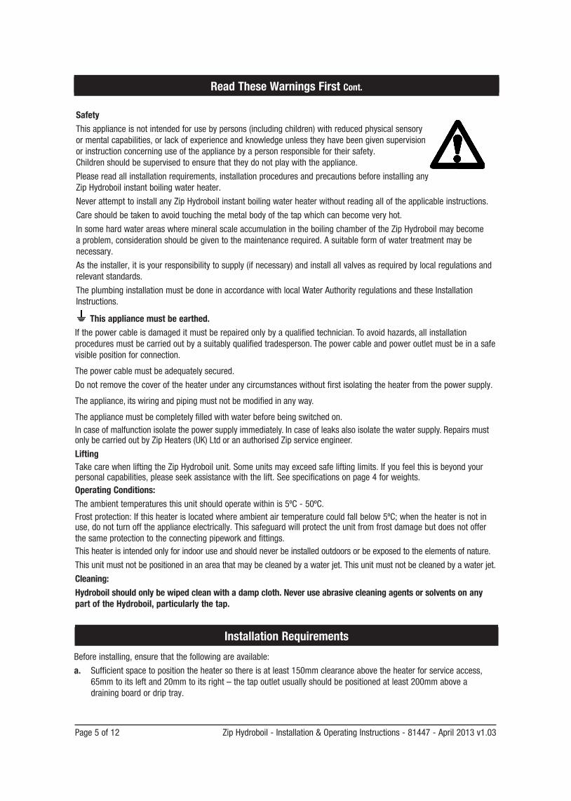
SafetyThisapplianceisnotintendedforusebypersons(includingchildren)withreducedphysicalsensoryormentalcapabilities,orlackofexperienceandknowledgeunlesstheyhavebeengivensupervisionor instruction concerning use of the appliance by a person responsible for their safety. Childrenshouldbesupervisedtoensurethattheydonotplaywiththeappliance.
Pleasereadallinstallationrequirements,installationproceduresandprecautionsbeforeinstallinganyZipHydroboilinstantboilingwaterheater.
NeverattempttoinstallanyZipHydroboilinstantboilingwaterheaterwithoutreadingalloftheapplicableinstructions.
Careshouldbetakentoavoidtouchingthemetalbodyofthetapwhichcanbecomeveryhot.
InsomehardwaterareaswheremineralscaleaccumulationintheboilingchamberoftheZipHydroboilmaybecomeaproblem,considerationshouldbegiventothemaintenancerequired.Asuitableformofwatertreatmentmaybenecessary.
Astheinstaller,itisyourresponsibilitytosupply(ifnecessary)andinstallallvalvesasrequiredbylocalregulationsandrelevant standards.
TheplumbinginstallationmustbedoneinaccordancewithlocalWaterAuthorityregulationsandtheseInstallationInstructions.
Read These Warnings First Cont.
This appliance must be earthed.Ifthepowercableisdamageditmustberepairedonlybyaqualifiedtechnician.Toavoidhazards,allinstallationproceduresmustbecarriedoutbyasuitablyqualifiedtradesperson.Thepowercableandpoweroutletmustbeinasafevisible position for connection.
Thepowercablemustbeadequatelysecured.
Donotremovethecoveroftheheaterunderanycircumstanceswithoutfirstisolatingtheheaterfromthepowersupply.
Theappliance,itswiringandpipingmustnotbemodifiedinanyway.
Theappliancemustbecompletelyfilledwithwaterbeforebeingswitchedon.Incaseofmalfunctionisolatethepowersupplyimmediately.Incaseofleaksalsoisolatethewatersupply.RepairsmustonlybecarriedoutbyZipHeaters(UK)LtdoranauthorisedZipserviceengineer.
LiftingTakecarewhenliftingtheZipHydroboilunit.Someunitsmayexceedsafeliftinglimits.Ifyoufeelthisisbeyondyourpersonalcapabilities,pleaseseekassistancewiththelift.Seespecificationsonpage4forweights.Operating Conditions:Theambienttemperaturesthisunitshouldoperatewithinis5ºC-50ºC.Frostprotection:Ifthisheaterislocatedwhereambientairtemperaturecouldfallbelow5ºC;whentheheaterisnotinuse,donotturnofftheapplianceelectrically.Thissafeguardwillprotecttheunitfromfrostdamagebutdoesnotofferthesameprotectiontotheconnectingpipeworkandfittings.Thisheaterisintendedonlyforindooruseandshouldneverbeinstalledoutdoorsorbeexposedtotheelementsofnature.
Thisunitmustnotbepositionedinanareathatmaybecleanedbyawaterjet.Thisunitmustnotbecleanedbyawaterjet.
Cleaning: Hydroboil should only be wiped clean with a damp cloth. Never use abrasive cleaning agents or solvents on any part of the Hydroboil, particularly the tap.
Installation Requirements
Beforeinstalling,ensurethatthefollowingareavailable:
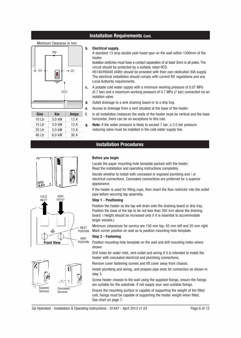
a. Sufficientspacetopositiontheheatersothereisatleast150mmclearanceabovetheheaterforserviceaccess,65mmtoitsleftand20mmtoitsright–thetapoutletusuallyshouldbepositionedatleast200mmaboveadraining board or drip tray.
Zip Hydroboil - Installation & Operating Instructions - 81447 - April 2013 v1.03 Page 6 of 12
Before you beginLocatethepapermounting-holetemplatepackedwiththeheater. Readtheinstallationandoperatinginstructionscompletely.
Decidewhethertoinstallwithconcealedorexposedplumbingand/orelectrical connections. Concealed connections are preferred for a superior appearance.
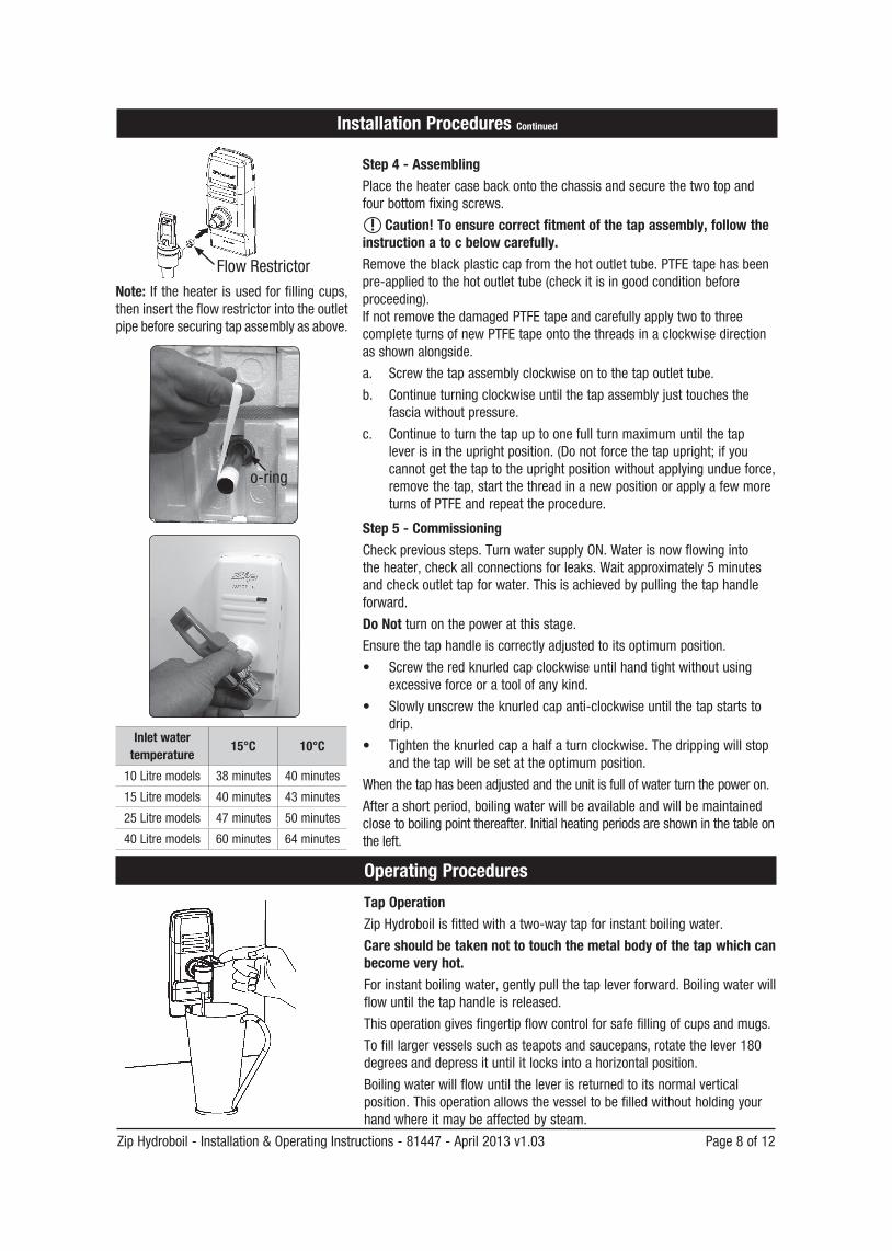
Iftheheaterisusedforfillingcups,theninserttheflowrestrictorintotheoutletpipebeforesecuringtapassembly.
Step 1 - PositioningPositiontheheatersothetapwilldrainontothedrainingboardordriptray.Positionthebaseofthetaptobenotlessthan200mmabovethedrainingboard.(Heightshouldbeincreasedonlyifitisessentialtoaccommodatelargervessels.)
Minimumclearancesforserviceare150mmtop,65mmleftand20mmright.Markcornerpositiononwallsotopositionmounting-holetemplate.
Step 2 - FasteningPositionmounting-holetemplateonthewallanddrillmountingholeswhereshown.
Drillholesforwaterinlet,ventoutletandwiringifitisintendedtoinstalltheheaterwithconcealedelectricalandplumbingconnections.
Removecoverfasteningscrewsandliftcoverawayfromchassis.
Installplumbingandwiring,andpreparepipeendsforconnectionasshowninstep 3.
Screwheaterchassistothewallusingthesuppliedfixings, ensurethefixingsaresuitableforthesubstrate.Ifnotsupplyyourownsuitablefixings.
Ensurethemountingsurfaceiscapableofsupportingtheweightofthefilledunit,fixingsmustbecapableofsupportingtheheaterweightwhenfilled. See chart on page 7.
Installation Procedures
COLD INLET
VENTOUTLET
INLET POSITION
VENT POSITIONFront View
b. Electrical supply. Astandard13ampdoublepolefusedspuronthewallwithin1500mmoftheheater. Isolationswitchesmusthaveacontactseparationofatleast3mminallpoles.The circuit should be protected by a suitably rated RCD. HS140/HS040(40ltr)shouldbeprovidedwiththeirowndedicated30Asupply. TheelectricalinstallationshouldcomplywithcurrentIEEregulationsandanyLocalAuthorityrequirements.
c. Apotablecoldwatersupplywithaminimumworkingpressureof0.07MPa(0.7bar)andamaximumworkingpressureof0.7MPa(7bar)connectedviaanisolation valve.
d. Outletdrainagetoasinkdrainingboardortoadriptray.
e. Accesstodrainagefromaventsituatedatthebaseoftheheater.
f. Inallinstallationinstancesthewallsoftheheatermustbeverticalandthebasehorizontal,therecanbenoexceptionstothisrule.
g. Note: Ifthewaterpressureislikelytoexceed7bar,a3.5barpressurereducingvalvemustbeinstalledinthecoldwatersupplyline.
Size Kw Amps10 Ltr 3.0kW 13 A15 Ltr 3.0kW 13 A25 Ltr 3.0kW 13 A40 Ltr 6.0kW 30 A
Installation Requirements Cont.
Concealed Services
ExposedServices
MinimumClearanceinmm
Page 7 of 12 Zip Hydroboil - Installation & Operating Instructions - 81447 - April 2013 v1.03
Installation Procedures Continued
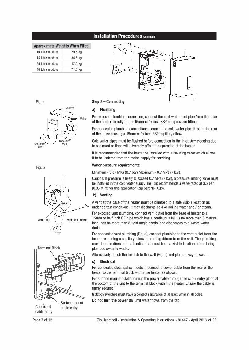
Approximate Weights When Filled10Litremodels 29.5kg
15Litremodels 34.5kg
25Litremodels 47.0kg
40Litremodels 71.0kg
250mm
Wiring
Concealed VentConcealed
Inlet
45mm
Fig. b
Fig. a
VisibleTundishVentline
Surfacemountcable entry
TerminalBlock
Concealed cable entry
Step 3 – Connecting
a) Plumbing
Forexposedplumbingconnection,connectthecoldwaterinletpipefromthebaseoftheheaterdirectlytothe15mmor1/2inchBSPcompressionfittings.
Forconcealedplumbingconnections,connectthecoldwaterpipethroughtherearofthechassisusinga15mmor1/2inchBSPcapillaryelbow.
Coldwaterpipesmustbeflushedbeforeconnectiontotheinlet.Anycloggingduetosedimentorfineswilladverselyaffecttheoperationoftheheater.
Itisrecommendedthattheheaterbeinstalledwithaisolatingvalvewhichallowsittobeisolatedfromthemainssupplyforservicing.
Water pressure requirements:
Minimum-0.07MPa(0.7bar)Maximum-0.7MPa(7bar).
Caution:Ifpressureislikelytoexceed0.7MPa(7bar),apressurelimitingvalvemustbeinstalledinthecoldwatersupplyline.Ziprecommendsavalveratedat3.5bar(0.35MPa)forthisapplication(ZippartNo.AQ3).
b) Venting
Aventatthebaseoftheheatermustbeplumbedtoasafevisiblelocationas,undercertainconditions,itmaydischargecoldorboilingwaterand/orsteam.
Forexposedventplumbing,connectventoutletfromthebaseofheatertoa 15mmorhalfinchODpipewhichhasacontinuousfall,isnomorethan3metreslong,hasnomorethan3rightanglebends,anddischargestoawastewaterdrain.
Forconcealedventplumbing(Fig.a),connectplumbingtotheventoutletfromtheheaterrearusingacapillaryelbowprotruding45mmfromthewall.Theplumbingmustthenbedirectedtoatundishthatmustbeinavisiblelocationbeforebeingplumbedawaytowaste.
Alternativelyattachthetundishtothewall(Fig.b)andplumbawaytowaste.
c) ElectricalForconcealedelectricalconnection,connectapowercablefromtherearoftheheatertotheterminalblockwithintheheaterasshown.
Forsurfacemountinstallationrunthepowercablethroughthecableentryglandatthebottomoftheunittotheterminalblockwithintheheater.Ensurethecableisfirmlysecured.
Isolationswitchesmusthaveacontactseparationofatleast3mminallpoles.
Do not turn the power ONuntilwaterflowsfromthetap.
Zip Hydroboil - Installation & Operating Instructions - 81447 - April 2013 v1.03 Page 8 of 12
Tap OperationZipHydroboilisfittedwithatwo-waytapforinstantboilingwater.
Care should be taken not to touch the metal body of the tap which can become very hot.Forinstantboilingwater,gentlypullthetapleverforward.Boilingwaterwillflowuntilthetaphandleisreleased.
Thisoperationgivesfingertipflowcontrolforsafefillingofcupsandmugs.
To fill larger vessels such as teapots and saucepans, rotate the lever 180 degreesanddepressituntilitlocksintoahorizontalposition.
Boilingwaterwillflowuntiltheleverisreturnedtoitsnormalverticalposition.Thisoperationallowsthevesseltobefilledwithoutholdingyourhandwhereitmaybeaffectedbysteam.
Inlet water temperature
15°C 10°C
10Litremodels 38minutes 40minutes
15Litremodels 40minutes 43minutes
25Litremodels 47minutes 50minutes
40Litremodels 60minutes 64minutes
Operating Procedures
Step 4 - AssemblingPlacetheheatercasebackontothechassisandsecurethetwotopandfourbottomfixingscrews.
Caution! To ensure correct fitment of the tap assembly, follow the instruction a to c below carefully.Removetheblackplasticcapfromthehotoutlettube.PTFEtapehasbeen pre-appliedtothehotoutlettube(checkitisingoodconditionbeforeproceeding). IfnotremovethedamagedPTFEtapeandcarefullyapplytwotothreecompleteturnsofnewPTFEtapeontothethreadsinaclockwisedirectionasshownalongside.
a. Screwthetapassemblyclockwiseontothetapoutlettube.
b. Continueturningclockwiseuntilthetapassemblyjusttouchesthefasciawithoutpressure.
c. Continuetoturnthetapuptoonefullturnmaximumuntilthetapleverisintheuprightposition.(Donotforcethetapupright;ifyoucannotgetthetaptotheuprightpositionwithoutapplyingundueforce,removethetap,startthethreadinanewpositionorapplyafewmoreturns of PTFE and repeat the procedure.
Step 5 - CommissioningCheckprevioussteps.TurnwatersupplyON.Waterisnowflowingintotheheater,checkallconnectionsforleaks.Waitapproximately5minutesandcheckoutlettapforwater.Thisisachievedbypullingthetaphandleforward.
Do Not turnonthepoweratthisstage.Ensurethetaphandleiscorrectlyadjustedtoitsoptimumposition.
• Screwtheredknurledcapclockwiseuntilhandtightwithoutusingexcessiveforceoratoolofanykind.
• Slowlyunscrewtheknurledcapanti-clockwiseuntilthetapstartstodrip.
• Tightentheknurledcapahalfaturnclockwise.Thedrippingwillstopandthetapwillbesetattheoptimumposition.
Whenthetaphasbeenadjustedandtheunitisfullofwaterturnthepoweron.
Afterashortperiod,boilingwaterwillbeavailableandwillbemaintainedclosetoboilingpointthereafter.Initialheatingperiodsareshowninthetableonthe left.
Installation Procedures Continued
o-ring
Note: If the heater is used for filling cups, theninserttheflowrestrictorintotheoutletpipebeforesecuringtapassemblyasabove.
FlowRestrictor
Page 9 of 12 Zip Hydroboil - Installation & Operating Instructions - 81447 - April 2013 v1.03
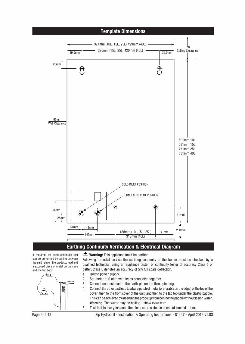
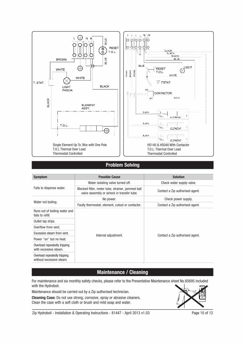
Earthing Continuity Verification & Electrical Diagram
Template Dimensions
If required, an earth continuity testcanbeperformedbytestingbetweenthe earth pin on the products lead and aexposedpieceofmetalonthecaseand the tap body.
39.5mm39.5mm
41mm
41mm
41mm
145mm
42mm
20mm
28mm
54mm
150Ceiling Clearance
65mm Wall Clearance
591mm10L 591mm15L 771mm25L 831mm40L
374mm(10L,15L,25L)499mm(40L)
295mm(15L,25L)420mm(40L)
188mm(10L,15L,25L)313mm(40L)
200mm
CONCEALEDVENTPOSITION
COLD INLET POSITION
Warning:Thisappliancemustbeearthed.Following remedial service the earthing continuity of the heater must be checked by aqualified technician using an appliance tester, or continuity tester of accuracy Class 5 orbetter. Class 5 denotes an accuracy of 5% full scale deflection.1. Isolatepowersupply.2. Setmeterto0ohmwithleadsconnectedtogether.3. Connect one test lead to the earth pin on the three pin plug.4. Connecttheothertestleadtoabarepatchofmetal(preferablyontheedge)ofthetopofthe
cover, then to the front cover of the unit, and then to the tap top under the plastic paddle. Thiscanbeachievedbyinsertingtheprobeupfrombehindthepaddlewithoutlosingwater. Warning:Thewatermaybeboiling-showextracare.
5. Testthatineveryinstancetheelectricalresistancedoesnotexceed1ohm.
Zip Hydroboil - Installation & Operating Instructions - 81447 - April 2013 v1.03 Page 10 of 12
Problem Solving
Symptom Possible Cause Solution
Failstodispensewater.Water isolating valve turned off. Checkwatersupplyvalve.
Blockedfilter,metertube,strainer,jammedballvalveassemblyorairlockintransfertube.
Contact a Zip authorised agent.
Water not boiling.Nopower. Checkpowersupply.
Faultythermostat,element,cutoutorcontactor. Contact a Zip authorised agent.
Runsoutofboilingwaterandfails to refill.
Internaladjustment. Contact a Zip authorised agent.
Outlet tap drips.
Overflowfromvent.
Excessivesteamfromvent.
Power“on”butnoheat.
Overload repeatedly tripping withexcessivesteam.
Overload repeatedly tripping withoutexcessivesteam.
Maintenance / Cleaning
Formaintenanceandsixmonthlysafetychecks,pleaserefertothePreventativeMaintenancesheetNo.85695includedwiththeHydroboil.
MaintenanceshouldbecarriedoutbyaZipauthorisedtechnician.
Cleaning Case: Do not use strong, corrosive, spray or abrasive cleaners. Cleanthecasewithasoftclothorbrushandmildsoapandwater.
SingleElementUpTo3KwwithOnePole T.O.LThermalOverLoad ThermostatControlled
HS140 & HS040 With ContactorT.O.L:ThermalOverLoadThermostatControlled
Page 11 of 12 Zip Hydroboil - Installation & Operating Instructions - 81447 - April 2013 v1.03
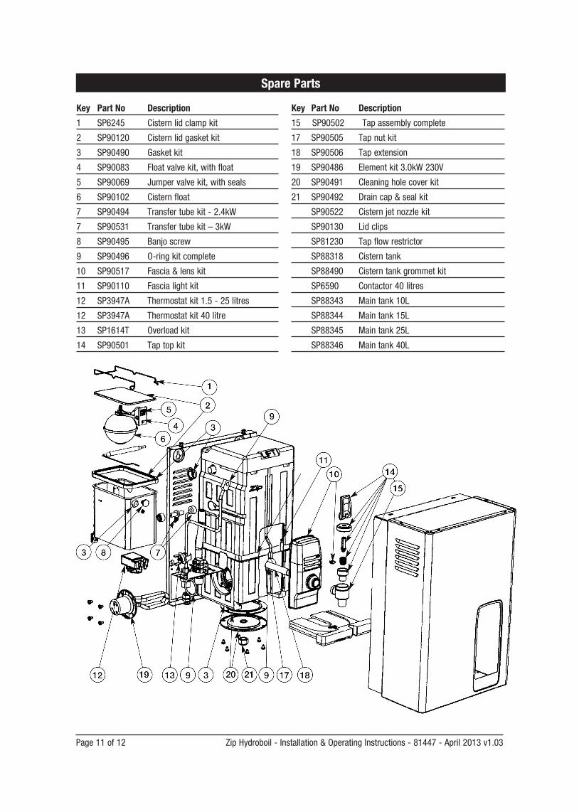
Spare Parts
Key Part No Description
1 SP6245 Cisternlidclampkit
2 SP90120 Cisternlidgasketkit
3 SP90490 Gasketkit
4 SP90083 Floatvalvekit,withfloat
5 SP90069 Jumpervalvekit,withseals
6 SP90102 Cistern float
7 SP90494 Transfertubekit-2.4kW
7 SP90531 Transfertubekit–3kW
8 SP90495 Banjoscrew
9 SP90496 O-ringkitcomplete
10 SP90517 Fascia&lenskit
11 SP90110 Fascialightkit
12 SP3947A Thermostatkit1.5-25litres
12 SP3947A Thermostatkit40litre
13 SP1614T Overloadkit
14 SP90501 Taptopkit
Key Part No Description
15 SP90502 Tapassemblycomplete
17 SP90505 Tapnutkit
18 SP90506 Tapextension
19 SP90486 Elementkit3.0kW230V
20 SP90491 Cleaningholecoverkit
21 SP90492 Draincap&sealkit
SP90522 Cisternjetnozzlekit
SP90130 Lid clips
SP81230 Tapflowrestrictor
SP88318 Cisterntank
SP88490 Cisterntankgrommetkit
SP6590 Contactor 40 litres
SP88343 Maintank10L
SP88344 Maintank15L
SP88345 Maintank25L
SP88346 Maintank40L
Page 12 Zip Hydroboil - Installation & Operating Instructions - 81447 - April 2013 v1.03
Head Office
ZipHeaters(UK)Ltd14 Bertie Ward WayDerehamNorfolkNR191TE
Website:www.zipheaters.co.uk [email protected]: 0845 6 005 005Facsimile:01362692448.
Warranty Information
CertainwarrantiesmaybeimpliedbylawintoyourcontractwithZip.Thewarrantyprovidedbelowisadditionaltotheseimpliedwarrantiesandnothingsetoutbelowshalllimityourstatutoryrightsorrightsatlaw.
ZipHeaters(UK)Ltdwarrantsthat,shouldanypartfailwithin24calendarmonthsofinstallation,thatpartwillberepairedorreplacedfreeofchargebyZiporitsDistributororServiceProvider,exceptassetoutbelow,providedtheapplianceisinstalledandusedstrictlyinaccordancewiththeinstructionssupplied,andthatfailureisnotduetoaccident,misuse,abuse,unsuitablewaterconditions,ortoanyalteration,modificationorrepairbyanypartynotexpresslynominatedbyZip.
Nocostsarepayablebythecustomerotherthananymileageortravelling-timechargesincurredbyaZipServiceProviderorthecostofremoval,cartageandre-installationofanycomponentoftheapplianceifitneedstobereturnedforrepair to Zip or its Distributor.
Thiswarrantydoesnotcoverdamageresultingfromnon-operationoftheappliance,theuseofnonauthorisedpartsorconsequentialdamagetoanyother goods, furnishings or property.
Nowarrantyappliestothelifeofanyfiltrationcartridgeinstalledwiththeapplianceascartridgelifemayvaryaccordingtowaterqualityandtherateofwaterconsumption.
Zipdoesnotexclude,restrictormodifyanyliabilitythatcannotbeexcluded,restrictedormodifiedorwhichcannot,excepttoalimitedextent,beexcluded,restrictedormodifiedasbetweentheowneroruserandZipunderthelawsapplicable.
Furthermore,thiswarrantydoesnotdisplaceanystatutorywarranty,but,totheextenttowhichZipisentitledtodoso,theliabilityofZipunderanystatutorywarrantywillbelimitedatZip’soptiontothereplacementoftheapplianceorsupplyofequivalentappliance,thepaymentofthecostofreplacingtheapplianceoracquiringanequivalentappliance,orthepaymentofthecostofhaving the appliance repaired or the repair of the appliance.
Registering Your Purchase
RegisteringyourZipinstallationontheZipwebsitemayhelptoestablishdateofinstallationshoulditbecomenecessarytoservicetheapplianceundertermsoftheZipwarranty.Toregisteryourinstallationgotowww.zipheaters.co.ukandlookundertheheading“Warranty”.
End of life disposal
Theuseofthiscrossedoutwheeledbinlogoindicatesthatthisproductneedstobedisposedofseparatelytoanyotherhouseholdwaste.WithineachoftheEuropeanUnionmembercountries,provisionshavebeenmadeforthecollectionandrecyclingofunwantedelectricalandelectronicequipment.Inordertopreserveourenvironmentweaskthatyoudisposeofthisproductcorrectly.PleasecontactZipCustomerServiceforadviceon08456005005.